Abstract
This study focuses on a structural element bio-mimicked from the human cranium (HC) into a shell element. As the HC is effective in resisting intracranial pressure developed by the brain, a water tank was considered to use a bio-mimicked shape of a shell as a roof. An optimized numerical model was validated experimentally and compared with a conventional specimen. The structural behavior of the bio-mimicked specimen is similar and performs more efficiently than the conventional specimen in capacity ratio, crack formation, and load-carrying capacity. Methodology followed: A Computed Tomography (CT) scan of the HC was obtained in Digital Imaging and Communications in Medicine (DICOM) format for finite element analysis (FEA). From the geometric parameters of the HC, the radius of the curvature-to-thickness ratio was derived for the shell. The span and thickness of the shell under two criteria were considered. The spherical and circular shell behaviors were found to be similar to those of the HC, whereas the elliptical shell behavior was not. We studied the shape effect of the HC with the conventional slab and found that the HC shape has an impact on the behavior and is the most efficient. A bio-mimicked mono column was considered as a supporting column for the water tank and analyzed. Overall, adopting this bio-mimicking of the HC into the shell roof connects nature with sustainable architecture.
1. Introduction
Biomimicry is the process of obtaining solutions from nature to solve complex human problems. Biomimicry also makes a balance with nature in the production of materials in the field of architecture and in various fields of engineering and science to live in congruence with Mother Nature [1,2]. This concept has paved the way for a new mode of living in a sustainable manner, and many new methods have been developed to improve structures in their structural as well as aesthetic appearance [3,4]. The term biomimicry has its origin in the Greek words ‘bios’, meaning life, and ‘mimics’, meaning to imitate, and was first coined by Janine Benyus [5,6]. Nature is a 3.8-billion-year-old teacher who teaches humans to solve challenges in a sustainable and environment-friendly manner [7]. As the concept of biomimicry follows nature’s unifying patterns to solve problems, this concept is found to be one of the emerging technologies in the field of engineering and science. An example of biomimicry is L’Hemisferic in Spain, shown in Figure 1a,b, which was constructed by adopting the shape of the human eye. The structure portrays the form of an eyelid that unlocks to access the surrounding water pool. The Egg Theatre in New York and the City Hall in London, shown in Figure 2a–c, had their inspiration from eggshells. The architects designed the building in such a way that the structures are sustainable and non-polluting buildings. This shape led to a reduction in surface area and increased energy efficiency. This method of mimicking shapes is termed biomorphism [5].
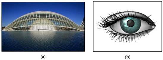
Figure 1.
(a) L’Hemisferic, Spain, inspired by (b) human eye shape [5].
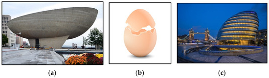
Figure 2.
(a) The Egg Theatre, New York; (b) Eggshell; and (c) City Hall, London [5].
In the field of engineering, the structural element frame was modeled by optimizing the shape for tension and compression members by mimicking the shape of the humerus and femur bones, respectively. They developed this idea as the human body is a slender system of bones. The coniferous trees were also drawn as an inspiration for reinforcement in the concrete columns [8]. Motherway et al. (2009) investigated the mechanical properties of the cranial bone [9]. Using finite element analysis, the dynamic characteristics of the cranium were studied by Huang et al. (2009) and the effect of von-mises stress in the adult skull by Haen et al. (2017) [10,11]. The accuracy of the Finite Element Method (FEM) is highly dependent on higher-resolution scans with fine anatomical details, and it facilitates the allocation of more precise, heterogeneous material properties [12].
There are various forms of structural roofing systems in which shell structures are preferred for their less displacement and structural efficiency compared with flat roofs. Shell structures are formed by one or more curved plates or folded plates having less thickness than other dimensions [13]. To reduce the self-weight and the application of imposed loads, shell roofing systems are preferred in this modern-day technology [14]. The major factors that affect the behavior and efficiency of shells are their shape and thickness [15,16]. Sindhu Nachiar et al. (2022) optimized the shape of the spherical thin shell structure by varying the radius of the curvature-to-thickness ratio and geometric parameters [17]. Meng et al. (2022) developed a new method for shape–thickness–topology for free-form shells [18]. Smoljanovic et al. (2021) considered the geometric parameters, rotations, strains, and displacements for analysis and concluded that the structured mesh was more effective than the unstructured one. The non-linearity of the shell increases with an increase in thickness [19,20]. Tahaseen (2016) designed a reinforced cement concrete dome by calculating the meridional thrust and hoop stress [21]. For any thin shell, the geometry has to be perfect to resist the buckling and post-buckling load, as any imperfections will be very sensitive [22,23]. Many numerical methods were developed for resisting the buckling load and external pressure in domes, such as the Sanders theory and Donnell’s theory [24]. The shape of the dome encloses maximum space and is found to be economical as it requires less labor compared with other flat roofs [25].
An elevated water tank with a mono column was selected for this study analysis since the column height determines the performance and seismic behavior of the water tank [26]. Similarly, the shape of the water tank holds a significant effect on the storage capacity and thermal stratification of the structure [27]. The spherical shape exhibited better behavior than the cylindrical shape [28,29]. For inspecting the performance of the elevated storage tank, robot inspection was suggested instead of primitive methods, as it resulted in obtaining abundant quantitative results [30].
The major aim of this study is to implement the concept of bio-mimics in developing a shell roof system for a water tank by mimicking the shape of the HC (Figure 3a). The human skull consists of two parts: the neurocranium and the viscero-cranium. The neurocranium is the thin structure that protects the human brain from sudden impact and injuries. For comparative purposes, a line diagram of the conventional shell is illustrated in Figure 3b. A statistical approach of linear regression analysis helps in identifying and arriving at a dependency equation and coefficient of error with a confidence level of 95%. Since the main advantage of using regression analysis is the accuracy in predicting the properties and arriving at a simplified equation for the same, the scope of this study includes the geometric parameters of the human skull and shell for arriving at an optimized shape for the shell and the regression equation for the prediction of the stress from the bio-mimicked shell element.
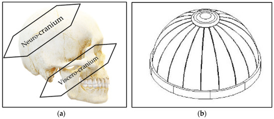
Figure 3.
(a) Skull of human (cranium) and (b) line diagram of shell.
Thrust of This Study
A shell’s structural elements are regular and symmetric in shape. The objective of this study is to adopt the skeletal system (cranium) into a shell considering equivalent stress. The HC has default resistance to intracranial pressure (ICP) due to its shape factor and properties. Therefore, the thrust of this study is to mimic the HC’s geometric characteristics and properties into an effective shell as the roof of the water tank and to verify it experimentally. Since the concept of bio-mimics in developing shells is very limited, this study focused on the bio-mimics of the HC and used FEA on three different types of shells, spherical, circular, and elliptical in shape, which are almost similar to the shape of the HC by varying geometric characteristics. For a complete structural system, a water tank was selected so that the bio-mimicked shell element could be used as a roof.
2. Methodology
Computed Tomography (CT) scan images of the HC of both males and females were obtained in Digital Imaging and Communications in Medicine (DICOM) format for FEA. The DICOM format was converted into a 3D model. From the CT scan images, geometric parameters such as breadth, anterior–posterior length, and average thickness were measured. As per the literature, the standard geometric parameters for the HC in India were adopted for deriving the ratio (), where R is the radius of the curvature and t is the thickness of the shell, to compare the same with the parameters measured from the obtained CT scan images. In this study, two criteria were considered: fixing the span of the shell and varying thickness and vice versa. The FEA was performed for the three shapes of shells (spherical, circular, and elliptical) and the 3D model of the HC using ANSYS 18.1. The constitutive models considered for this study were linear elastic. The stress pattern of the cranium was considered to optimize the shell for further analysis. For using an optimized shell as an element, a water tank with a mono column was selected. For the mono column, three different shapes, including a circular column, a stepped column, and a bio-mimic of a femur bone, were also analyzed. Finally, the most efficient supporting column for the optimized shell was determined. The performance of the optimized column with the shell as a whole structural element for the water tank was experimentally verified with the numerical results. The mold was fabricated, cast, and tested for the application of a lateral load and water pressure to check the structural performance of the bio-mimicked water tank and compare it with the conventional water tank.
3. Parametric and Properties
In this section, the geometric and material properties of the cranium and conventional shell shapes are considered, and the parametric range for the two criteria adopted is detailed. The concrete constituents used and their properties are also presented. These concrete constituents were used for the experimental investigation. Model shapes and parametric ranges used for the numerical study are discussed in this section. Also, the selection of column shapes to support the proposed shell roof is described.
3.1. Cranium Properties
The average value of geometric characteristics such as anterior–posterior length, breadth, and thickness of males and females are measured using the DICOM viewer from the obtained CT scan images. The measured values and values from the literature are given in Table 1.

Table 1.
Geometric characteristics of cranium.
The ratios obtained were found to be 10.80 and 11.10, respectively, which is less than 20 as per IS 2210:1988 [33], and hence, the cranium can be classified as a shell. The cranial capacity of the skull was calculated using the Lee–Pearson formula [31,32].
Cranial capacity for male skull: 0.000337 (L − 11) (B − 11) (H − 11) + 406.01
Cranial capacity for female skull: 0.0004 (L − 11) (B − 11) (H − 11) + 206.60
Generally, the cranial capacity of the male skull is higher than that of the female skull. Also, it was found that the male cranium has more capacity than the female cranium. Therefore, in this study, FEA was carried out for the male cranium. The material properties of the cranium, such as modulus of elasticity, Poisson’s ratio, and density, were adopted as suggested by Zapata et al. (2020) for the numerical investigation of shells and are given in Table 2 [34].
Table 2.
Material properties of the cranium.
3.2. Concrete Mix Proportions
Ordinary Portland Cement (OPC) of grade 53 as per IS 12269:2016 [35] and a specific gravity of 3.15, and Animal Bone Powder (ABP) of a specific gravity of 1.95 were used as a binder to replace cement by 10% to match the properties of the human skull. Manufactured sand (M-Sand) conforming to Zone II as per IS 383:2016 [36] with a specific gravity of 2.65 and a crushed-stone aggregate of size 10–12.5 mm and with a specific gravity of 2.67 were used as fine and coarse aggregates, respectively, for concrete production. Superplasticizers of naphthalene base and potable water were used in this study. The physical and chemical composition of the binder used are presented in Table 3.
Table 3.
Physical and chemical compositions of binders.
3.3. Models Shapes and Parametric Ranges
From the conventional shapes of the shells, three different shapes, including spherical, circular, and elliptical shells, shown in Figure 4a–c, respectively, were selected for comparative analysis. Since the ratio (rise to span) of less than falls under the hollow shell for spherical shells, the ratio from to was adopted as per IS 2210: 1988 [33]. For circular shells, the rise-to-span ratio adopted was , as it is obligatory. The ellipticity ratio (ratio of semi-minor axis to major axis) was used to define the parameters of the elliptical shell. In this study, the ellipticity ratio was found to be 1.36 based on the geometric characteristics of the cranium, which classify it as an oblate ellipsoid.
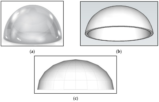
Figure 4.
Shell shapes considered: (a) spherical, (b) circular, and (c) elliptical.
As per IS 2210:1988 [33], the maximum span and minimum thickness of the shell are limited to 30.00 m and 40.00 mm, respectively. Therefore, considering this limitation, for the different ratios, the ranges for parameters such as span, rise, and thickness were calculated for the three adopted shapes of shells and for various rise-to-span ratios. The different ranges for span, rise, and thickness for different rise-to-span ratios for spherical, circular, and elliptical shapes are shown in Table 4. For ease of identification, for spherical shells to , S5 to S10 are used as notations (example: as S5 and as S10). Similarly, C is used as a notation for the circular shell, and E is used for the elliptical shell. There are 24 different cases in total considered for analysis purposes in which the two different criteria mentioned earlier were adopted. An increment of 50 mm for thickness and 500 mm for span was considered for each case. In total, there were 510 models created and analyzed. From Table 4, it can be noted that though the minimum and maximum thickness parameters calculated are 0.04 m and 3.61 m, respectively, beyond a certain limit, thickness is practically not viable. Hence, this was considered for the numerical investigation in this study.
Table 4.
Parametric ranges for ratio.
3.4. Analysis of Column Shapes to Support the Shell Roof
For the optimized shell size and shape to mimic the cranium, it is proposed to support a mono column. For this purpose, conventional circular and stepped-type shapes of columns were considered. Also, from the literature [39], the shape bio-mimicked from the femur bone was adopted to arrive at the most efficient supporting member for the water tank. Figure 5a,b represent the circular and stepped columns, respectively. Figure 5c shows the compression member bio-mimicked from the femur bone.
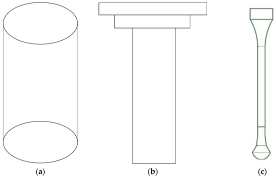
Figure 5.
Shapes of column considered: (a) circle, (b) stepped, and (c) bio-mimicked femur bone.
4. Numerical Investigation
A numerical investigation using FEA was carried out for the mesh convergence study and optimization of the cranium into a shell. The model of the cranium, modeling of the shell shapes, mesh convergence, and loading and boundary conditions are detailed in this section.
4.1. Model of Cranium
The 3D model was generated and analyzed from the cranium scan images. Over the created models, triangular meshes of size 3 mm were created since the trapezoidal meshes are not feasible for the cranium. The developed 3D model and the imported model are shown in Figure 6a,b, respectively. Also, a triangular mesh of size 3 mm was created for the imported cranium model, as shown in Figure 6c.
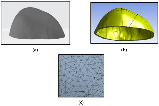
Figure 6.
(a) 3D model of cranium, (b) imported model, and (c) triangular mesh.
4.2. Model of Shell Shapes
As mentioned earlier, shell shapes were modeled, and they were generated by varying the parameters for each criterion for all types. The spherical, circular, and elliptical models generated are shown in Figure 7a–c, respectively.
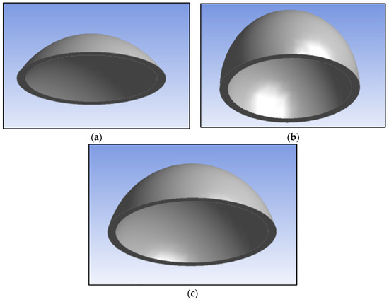
Figure 7.
Modeled shells, (a) spherical, (b) circular, and (c) elliptical.
4.3. Mesh Convergence Study
The mesh convergence study was carried out for the three modeled shell shapes by applying a pressure of 1 kN/m2 to the external face of the models with the base fixed as a boundary condition. The mesh convergence study was not supported by the software for mesh sizes below 70 mm, and more deviations were found compared to theoretical stress when the mesh sizes went above 200 mm. Therefore, the minimum and maximum mesh sizes considered were 70 and 500 mm (for confirmation), respectively. At the beginning, a 10 mm increment was followed from 70 to 100 mm and thereafter, a 50 mm increment was followed till 500 mm. The theoretical stress was calculated as suggested in the literature [40] and compared with the equivalent numerical stress to converge the mesh sizes. From the mesh convergence study, the optimized mesh sizes were found to be 80 mm for the shell models S5 to S7, C, and E. Likewise, for the S8 and S9 models, the mesh size was 90 mm, and for the S10 model, it was 100 mm.
4.4. Load and Boundary Condition for Shell Models
Here also, a pressure of 1 kN/m2 was applied to the external face of the cranium with the base fixed as a boundary condition, as shown in Figure 8a,b, respectively. The same loading and boundary conditions were followed for the analysis of the shells of both criteria.
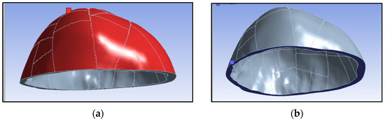
Figure 8.
(a) Pressure on the external face and (b) fixed at base.
5. Numerical Analysis
The cranium and shell models were analyzed for equivalent stress and displacement. From the 510 models analyzed, the best-fit models on par with the stress of the cranium were optimized. The details of the analysis of the cranium, biomorphism of the shells, comparison of the HC shape with the conventional slab, and the biomorphism of the water tank are discussed in this section.
5.1. Analysis of Cranium
From the analysis of the cranium, the equivalent stress and the displacement were obtained as 25.96 kN/m2 and 4.56 × 10⁻⁷ m, respectively. The maximum stress for the cranium was observed at the edges and the minimum stress at the crown. The maximum displacement was observed at the external face of the crown (i.e., at the frontal region of the cranium). The stress pattern and displacement pattern are shown in Figure 9a,b, respectively.
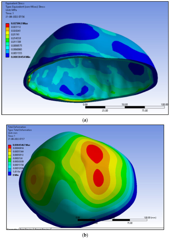
Figure 9.
Analysis of cranium: (a) equivalent stress and (b) displacement.
5.2. Biomorphism of Shells
For criterion 1 adopted (constant span, varying thickness), based on the stress results of the cranium and shell models, the shape was optimized. The equivalent stress pattern and displacement pattern for the S5 model are shown in Figure 10a,b, respectively. Similar stress and displacement patterns were observed for S6–S10, C, and E shells. From the displacement obtained from the models analyzed, the graphs were plotted for each criterion to conclude the behavior of the shells under different parameters. The shape of the shell was optimized by considering stress equivalent to that of the HC. The stress pattern and displacement pattern for all the analyzed models are found to be similar to that of the HC, as shown in Figure 9. A similar procedure was followed for criterion 2 (constant thickness, varying span) and for each shape of the shell.
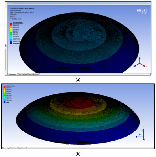
Figure 10.
For the S5 model: (a) equivalent stress pattern and (b) displacement pattern.
Similar stress and displacement patterns were observed for both criteria 1 and 2. The displacements versus thickness for both ratios (10.803 and 11.101) for criterion 1 is shown in Figure 11a,b, and for criterion 2, it is shown in Figure 12a,b, respectively. From the graphs, it can be observed that changes in displacement due to an increase in the thickness and span of the shells are linear. All the types of shells adopted exhibited similar kinds of behavior. As the thickness increases, the displacement decreases, and as the span increases, the displacement increases, as it is traditional and applies here also. From the equivalent stress obtained from the models, the graphs were plotted for each criterion to find the optimized model similar to the HC. The graphs for both ratios (10.803 and 11.101) for criteria 1 and 2, along with the equivalent stress of the HC, are shown in Figure 13a,b and Figure 14a,b, respectively. From the graphs, the models with stress equivalent to that of the HC are optimized and tabulated in Table 5 for criterion 1 and Table 6 for criterion 2, respectively (Model numbers indicated as M7, M44, M63, … M458 against shape and criteria are out of 510 models analyzed). It can be seen from the graphs that none of the models in E shells behaved similarly to that of the HC. Therefore, the optimized models that can be considered are S5, S6, S7, S8, S9, S10, and C shells.
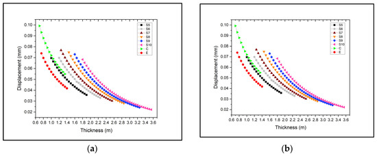
Figure 11.
Displacement vs. thickness: (a) for 10.803 and (b) for 11.101.
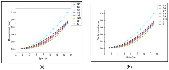
Figure 12.
Displacement vs. span: (a) for 10.803 and (b) for 11.101.
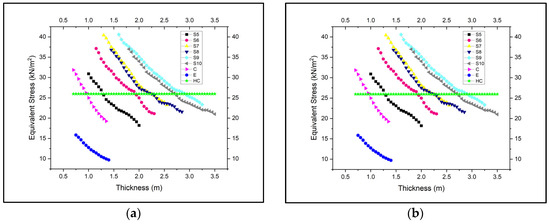
Figure 13.
Equivalent stress vs. thickness: (a) for 10.803 and (b) for 11.101.
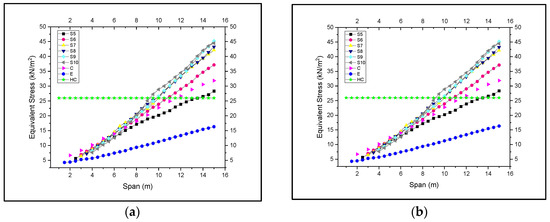
Figure 14.
Equivalent stress vs. span: (a) for 10.803 and (b) for 11.101.
Table 5.
Optimized shell models for criterion 1.
Table 6.
Optimized shell models for criterion 2.
From Table 5 and Table 6, it can be noted that the S7, S8, S9, and S10 models have greater thicknesses than rises. Since the thickness of the shell should be the smallest dimension [33], the S7, S8, S9 and S10 models were neglected. Also, the 13.5 m span and 1.83 m rise of S5 and S6 may not be suitable for practical conditions. Therefore, the models from criterion 2, S5 and S6, were also neglected. Therefore, C, S5, and S6 from criterion 1 and only C from criterion 2 were considered as optimized and hence selected for further numerical study. For these selected models, the ratio of maximum to average stress calculated from the FEM is shown in Table 7. The ratio of maximum to average stress of the HC is considered a benchmark (i.e., it should be equal to or less than for the selection of models from the analysis). These optimized models from the cranium analysis were compared with the same criteria for the conventional shell models S5 (M21) and C (M461). The models from the cranium and the conventional shell models were considered as roof elements for the analysis of the proposed water tank.
Table 7.
Ratio of maximum to average stress for the selected models.
5.3. Comparison of HC Shape with Conventional Slab
It was decided to study the shape effect of the HC with a conventional slab since the thickness (Table 3) is abnormal for the arrived () ratio from the HC. Therefore, the geometric parameters of the HC are converted into a slab to study the effect of the shape. A slab of dimension 0.175 × 0.145 × 0.0065 m reflecting the dimension of the HC was analyzed for the same loading and boundary conditions adopted as those of the HC. It was observed that the stress concentration (169.49 kN/m2) and displacement (2.3 × 10⁻⁵ m) of the slab were higher than those of the HC. The equivalent stress and displacement of the slab were observed to be more than 6.5 and 50 times those of the HC, respectively. However, the stress (Figure 15a) and displacement (Figure 15b) patterns were found to be similar to those of the HC.
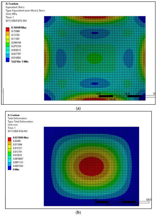
Figure 15.
Conventional slab: (a) stress pattern and (b) displacement pattern.
In continuation of the above, the slab was tested and analyzed for all the optimized cases. Here also, the same trends of higher stress concentration and displacements were found at the edges and the center of the slab, respectively. Therefore, a sample analysis is discussed here for the conventional S5 shell. For the S5 case, the equivalent slab dimension of 30 × 30 × 1.96 m reflecting the dimension of the conventional S5 was analyzed for the same loading and boundary conditions adopted for the shell. Here also, it was observed that the stress concentration (75.99 kN/m2) and displacement (1.14 × 10⁻³ m) of the slab were higher than those of the shell. The equivalent stress and displacement of the slab (S5) were observed to be more than 3 and 8 times those of the shell, respectively. However, the stress (Figure 16a) and displacement (Figure 16b) patterns were found to be similar to those of the shell.
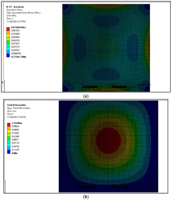
Figure 16.
Conventional slab similar to conventional S5: (a) stress pattern and (b) displacement pattern.
Hence, it can be concluded that the HC shape has an impact on the behavior, and thus, the shape of the HC is most efficient compared to conventional slabs based on the analysis.
5.4. Biomorphism of Water Tank
For further study, as mentioned earlier, the water tank was considered as an infrastructure. The immediate supporting elements of the roof, the ring beam, and the conical shell were designed by considering the stress value of the optimized shell from the analysis of the HC. The three different column shapes mentioned in Section 3.4 were used as supporting members for the water tank. The modeling of the water tank with different column shapes, such as circular, stepped, and bio-mimicked columns, are shown in Figure 17 for the spherical shell model M21. Similarly, the modeling of the water tank with different column shapes is shown in Figure 18 for the circular shell model M458.
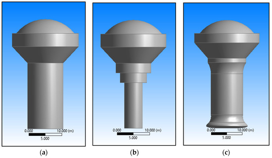
Figure 17.
Water tank models with M21 shell roof: (a) circular, (b) stepped, and (c) bio-mimicked columns.
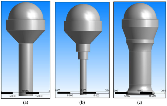
Figure 18.
Water tank models with M458 shell roof: (a) circular, (b) stepped, and (c) bio-mimicked columns.
The water tank was modeled using both optimized shells from the HC and conventional shells. These models were analyzed to arrive at the optimum shape of the supporting column for the water tank. For analysis, in addition to the boundary and loading conditions mentioned earlier, water pressure at three conditions, such as no water (empty tank), half-filled with water, and filled with water, was also considered. The maximum stress and displacement for M21 and M461 for the conventional models are shown in Table 8. Similarly, for the optimized models from HC M7 and M458, the maximum stress and displacement are shown in Table 9. It can be seen that the critical stress occurred when the water tank was half-filled.
Table 8.
Principal stress and displacement for conventional models.
Table 9.
Principal stress and displacement for optimized models.
The stress pattern for M21 at different water levels with the bio-mimicked column is shown in Figure 19, and a similar pattern was observed for models with stepped and circular columns. In the case of the tank filled with water, the maximum and minimum stresses were observed at the edges of the ring beam and the edges of the column, respectively. For half-filled and empty tanks, the maximum and minimum stresses were observed at the junction of the shell and ring beam, and the edge of the column, respectively. A similar stress pattern was found for the M7, M461, and M458 models under the three adopted water level conditions.
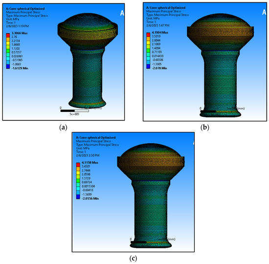
Figure 19.
Stress pattern of M21 with bio-mimicked column: (a) filled with water, (b) half-filled with water, and (c) no water (empty).
The displacement pattern for M21 at different water levels with bio-mimicked columns is shown in Figure 20, and a similar pattern was observed for models with stepped and circular columns. The maximum and minimum displacements were observed at the crown of the shell and the edges of the column for all the models at different levels of water.
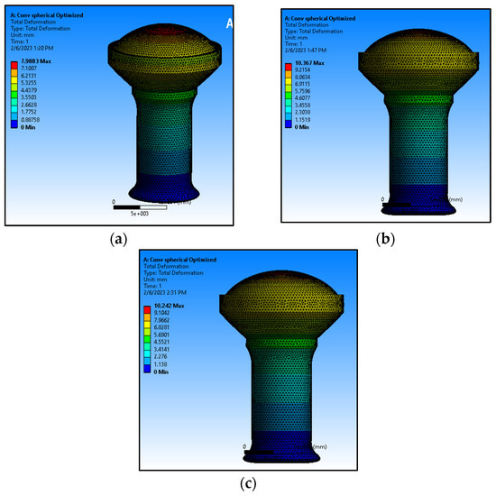
Figure 20.
Displacement pattern of M21 with the bio-mimicked column with water: (a) filled with water, (b) half-filled with water, and (c) no water (empty).
From the results of the maximum principal stress from the three cases, the critical stress was observed when the water tank was half-filled, irrespective of the shape of the shell and column. Therefore, this critical stress has to be considered for the design and detailing of the water tank. Hence, the stepped column support case was neglected for comparative analysis of the shell roof optimization.
6. Comparative Analysis
The critical stresses and the displacements of the optimized shells M7 and M458 with conventional shells M21 and M461 are compared with circular columns, and bio-mimicked columns are presented in this section.
6.1. Critical Stress Comparison
From the results obtained, it can be stated that for S5, the critical stress of optimized shell (M7) performance increased by 80% compared with the conventional shell (M21) with the circular column. Similarly, for S5 with the bio-mimicked column, the critical stress of the optimized shell (M7) performance increased by 5% compared to the conventional shell (M21). In the case of the ‘C’ optimized shell (M458), the critical stress decreased by 30% compared with the conventional shell (M461) with the circular column. Also, for ‘C’ with the bio-mimicked column, the critical stress for the M458 model decreased by 35% compared with the conventional shell model M461. Therefore, it can be concluded that the optimized S5 shell model (M7) performs better compared with the optimized ‘C’ shell model (M458) in both the cases of supporting columns with circular and bio-mimicked columns. The critical stress comparison for S5, for models M7 and M21, and C, for models M458 and M461, provided with both circular and bio-mimicked columns, is shown in Figure 21.
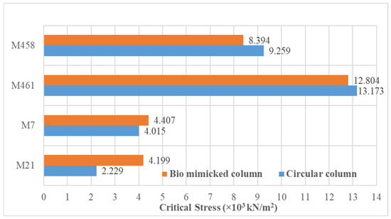
Figure 21.
Critical stress comparison for S5 and C.
6.2. Displacement Comparison
The displacement of the S5 optimized shell model (M7) increased by approximately 62% compared with the conventional shell (M21) with the circular column. Similarly, for S5 with the bio-mimicked column, the displacement of the optimized shell (M7) also increased by nearly 5% compared with the conventional shell (M21). Distinct from S5, the displacement of the optimized shell (M458) decreased by approximately 11% compared with the conventional shell (M461) with the circular column. For C with the bio-mimicked column, the displacement of the optimized shell (M458) decreased by approximately 38% compared with the conventional shell (M461). The displacement comparison for S5, for models M7 and M21, and for C, for models M458 and M461, provided with both circular and bio-mimicked columns, is shown in Figure 22.
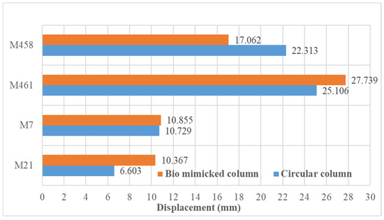
Figure 22.
Displacement comparison for S5 and C.
From the results obtained, it can be stated that the combination of the bio-mimicked shell with the bio-mimicked column is the most efficient with regard to performance compared with the conventional shell with the circular column. It can also be noted that the behavior of the bio-mimicked shell combined with the bio-mimicked column is akin to that of a conventional combination.
7. Experimental Investigation
The design of reinforcement, details of fabrication, and experimental setup are discussed in this section. The optimized water tank models in both bio-mimicked and conventional designs were adopted to experimentally validate the efficiency and performance of the numerical results.
7.1. Design and Details of Water Tank
Both conventional and bio-mimicked water tank models were scaled down based on load frame, accommodating the possible and accessible testing center at the institute. The specimen details used for both conventional and bio-mimicked water tanks are presented in this segment. For both types of specimens, the shell with a span of 650 mm, rise of 130 mm, and thickness of 40 mm throughout the specimen was adopted. A ring beam with a cross-section of 50 × 40 mm connects the upper shell and trapezoidal shell with a thickness of 40 mm, followed by a slab with a thickness of 40 mm and a span of 400 mm. A hollow column with a height of 850 mm and a diameter of 400 mm supports the water tank in both specimens. A slab with a height of 300 mm and a length of 700 mm at the base acts as fixed support for the water tank in both specimens. The thickness of the shell was fixed based on the codal provisions as per IS 2210:1988 [33]. The cross-sectional detailing of the conventional and bio-mimicked water tank specimens is shown in Figure 23a,b, respectively.
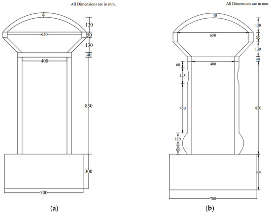
Figure 23.
Cross-sectional detailing of water tank specimen: (a) conventional and (b) bio-mimicked.
As the dimensions adopted for the prototype experimental investigation represented the real-life model, reinforcement detailing was provided by considering the minimum reinforcement percentage for each structural element in the specimen. Also, 6 mm diameter reinforcement bars were used other than the base slab for the specimen as the thickness was restricted to 40 mm. For the base slab, a 10 mm diameter was used as reinforcement. Steel of density 7850 kg/m3, Fe250 plain rebar, was used in this study. For numerical investigation, the type of element adopted for concrete was solid, and for the rebar, it was linked. The scaled-down model of both conventional and bio-mimicked specimens was once again modeled, analyzed, and used for comparisons with the experimental investigation.
7.2. Fabrication and Casting of Specimen
The specimens were fabricated and cast with ABP as a 10% replacement for cement. The mold fabricated and reinforcement adopted are shown in Figure 24. The cast specimen with numerical models for both conventional and bio-mimicked water tank specimens are shown in Figure 25 and Figure 26, respectively. After the specimens had been cast, plastic sheets were used and covered without any further delay to avoid water evaporation from the surface of the elements. Curing was carried out continuously for up to 28 days with a wet gunny bag, as shown in Figure 27.
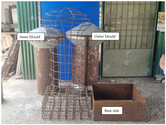
Figure 24.
Fabricated mold and reinforcement details for specimen.
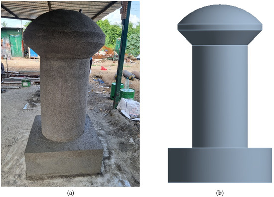
Figure 25.
Conventional water tank specimen: (a) cast specimen and (b) numerical model.
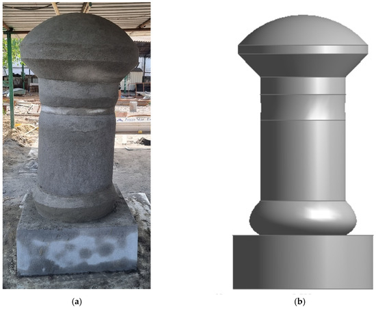
Figure 26.
Bio-mimicked water tank specimen: (a) cast specimen and (b) numerical model.
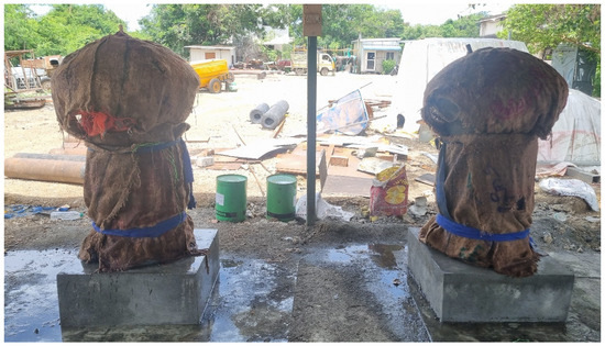
Figure 27.
Curing of bio-mimicked and conventional water tanks.
7.3. Experimental Setup
Specimens were whitewashed before testing, as shown in Figure 28. The specimen was placed in an upright position in the self-strained loading frame, having a capacity of 200 kN. The slab was fixed using clamps with bolts and nuts to restrain the movement during testing since the main aim was to study the lateral load behavior of the water tank. The total displacement of the shell was proposed to be measured exactly at the opposite of the load application point. A Linear Variable Differential Transformer (LVDT) was used to measure the deflection. Figure 29 and Figure 30 show the experimental setup arranged for testing conventional and bio-mimicked water tank specimens, respectively. The load point was selected at the face of the ring beam. Below the load point, a push–pull jack with a capacity of 50T and a load cell was used to observe the applied load. The load was applied monotonically. Also, the load was force-based; hence, the displacements were measured at each increment of the load. The load was applied over the element at a selected point, and water was filled to the top of the shell to consider the application of the water load with the provision of a hole in the top shell. Though the critical stress was observed with half-filled tanks in the numerical investigation, the tanks were filled completely during the testing of the specimen to avoid the sloshing effect and to withstand the water pressure in the shell. This water pressure mimics the intracranial pressure developed by the HC. The formation of cracks was monitored and noted during testing.
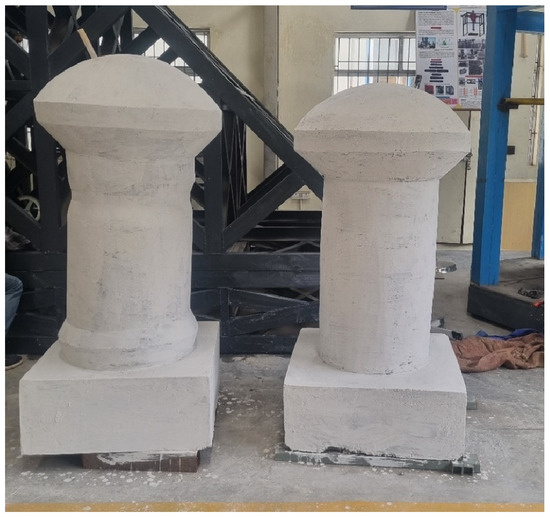
Figure 28.
Cast bio-mimicked and conventional specimens.
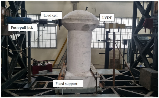
Figure 29.
Test setup for conventional water tank.
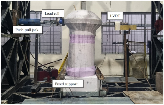
Figure 30.
Test setup for bio-mimicked water tank.
8. Results and Discussion
From the tests conducted on conventional and bio-mimicked water tank specimens, general observations, specimen strength, and load versus deflection behavior are discussed in this section.
8.1. General Observations
The conventional and bio-mimicked water tank specimen failure behavior was a typical structural failure. The formation of cracks was at the joints of the base slab and column. In both conventional and bio-mimicked water tank specimens, the cracks occurred only at the junction of the base slab and column, as seen in Figure 31a,b, respectively.
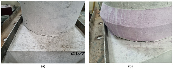
Figure 31.
Formation of crack: (a) conventional and (b) bio-mimicked water tank.
The occurred crack expanded along the junction of the base slab and column with the increment of load applied. No cracks other than at the junction were formed in both the conventional and bio-mimicked specimens. No cracking occurred in the specimen, even at the ultimate stage. However, deflection was continued with the application of the load. The same pattern of behavior was found in both specimens. Therefore, it can be stated that the behavior of conventional and bio-mimicked water tank specimens is similar. Also, the failure pattern observed in the numerical investigation, as shown in Figure 32, was found to be similar to the experimental results.
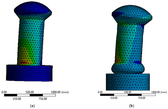
Figure 32.
Stress failure pattern: (a) conventional and (b) bio-mimicked water tank.
8.2. Capacity Ratio (Numerical)
From the numerical analysis, the ultimate load-carrying capacity of the conventional water tank specimen was found to be 110 kN, and for the bio-mimicked water tank specimen, it was found to be 150 kN. The capacity ratio of the specimen was calculated in comparison with that of the conventional specimen. The capacity ratio of the bio-mimicked specimen in comparison with load and stress are 1.36 and 4.05, respectively. The details of the comparisons are presented in Table 10.
Table 10.
Capacity ratio (numerical comparison).
8.3. Capacity Ratio (Experimental)
From the experimental results analysis, the ultimate load-carrying capacity of the conventional water tank specimen was found to be 118 kN, and for the bio-mimicked water tank specimen, it was found to be 156 kN. The capacity ratio of the specimen was calculated in comparison with that of the conventional specimen. The capacity ratio of the bio-mimicked specimen in comparison with load and stress are 1.32 and 2.80, respectively. The details of the comparisons are presented in Table 11.
Table 11.
Capacity ratio (experimental comparison).
8.4. Comparison (Numerical and Experimental)
From the numerical analysis, in comparison with the conventional specimen, the bio-mimicked specimen had a 36.36% higher load-carrying capacity and a 197.08% higher stress, respectively. Likewise, from the experimental analysis, in comparison with the conventional specimen, the bio-mimicked specimen had a 32.20% higher load-carrying capacity and a 179.82% higher stress, respectively.
8.5. Load–Displacement Behavior
The conventional and bio-mimicked specimens exhibited a similar load–displacement pattern. Figure 33 shows the load-versus-displacement curve of experimental values of the conventional and bio-mimicked specimens. Figure 34 shows the load-versus-displacement curve of numerical values of the conventional and bio-mimicked specimens. It can be observed that the load–displacement behavior in the numerical investigation is linear because of the ideal properties of the materials defined in the analysis. Also, no further crack was observed during the increment of the load. The displacement of the bio-mimicked specimen was comparatively less for the same amount of load applied to the conventional specimen. Overall, the load–displacement curves of both the conventional and bio-mimicked water tank specimens are almost linear. However, in this study, the cross-section, steel reinforcement, and concrete strength were fixed, and also, this study aimed to observe the behavior and capacity of the bio-mimicked specimen inspired by the human skull. Therefore, the limiting value of displacement to satisfy appearance was not considered.
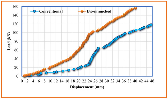
Figure 33.
Load–displacement curve for experimental investigation.
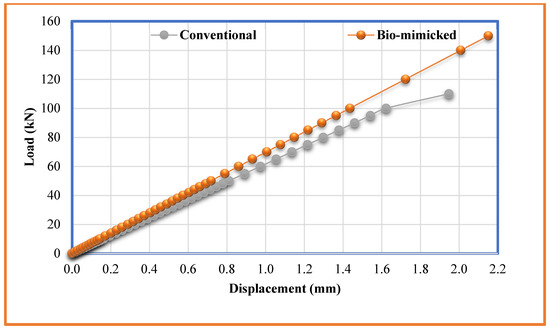
Figure 34.
Load–displacement curve for numerical investigation.
The displacements were measured in conventional and bio-mimicked specimens opposite to the point of application of the load, as shown in Table 12. As per IS 3370 (Part I): 2009 [41], the factor of safety of 1.2 was considered for the calculation of the service load. The displacements of conventional and bio-mimicked specimens at service load were 36.45 mm and 32.89 mm, respectively. The displacements of conventional and bio-mimicked specimens at ultimate load were 45.61 mm and 40.14 mm, respectively. It can be observed that the displacement of bio-mimicked specimens at the ultimate load was 13% less than the conventional. The results from the experimental investigation were found to be higher due to several factors, such as material properties, environmental conditions, handling errors, and also the test setup. The base was fixed in the numerical investigation. A similar setup with a fixed base was prepared manually. Thus, each stage of testing influences the experimental results. It is possible to restrict the displacement of monolithic elements by revising the sectional dimensions of the specimen and changing the reinforcement detailing and the strength of the concrete.
Table 12.
Displacement of conventional and bio-mimicked water tank specimen.
8.6. Crack Pattern
A crack occurred at the junction of the base slab and column for both the conventional and bio-mimicked specimens. For the conventional specimen, the crack occurred at a load of 77 kN, which was 70% of its ultimate load. Similarly, for the bio-mimicked specimen, the first crack was found at a load of 104 kN, which was 66% of its ultimate load. It seems that the bio-mimicked specimen also behaves in the same pattern of formation of cracks and almost at the same level of load capacity. The tested specimens are shown in Figure 35.
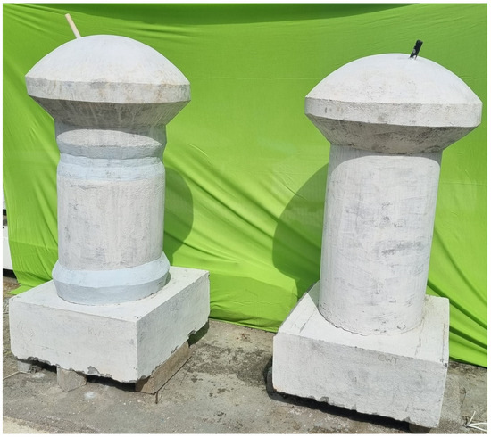
Figure 35.
Tested specimens.
9. Conclusions
The following conclusions were drawn from this study of bio-mimicking the human cranium into a shell along with a bio-mimicked mono column. The significant conclusion is that:
The conventional and bio-mimicked water tank specimen failure behavior was a typical structural failure. The bio-mimicked specimen performs more efficiently than conventional specimens in capacity ratio, formation of crack patterns, and load-carrying capacity. This study finds a structural element inspired by the human cranium (HC) into a shell element from the numerical and experimentally validated and hence connected nature into architecture by mimicking the cranium into a shell roof.
Further, the significant conclusions of this study are:
The shape of the HC is comparatively more efficient than the conventional slab. From the numerical results, it was found that the performance of the optimized shell (M7) increased by 80% and 62% compared with the conventional shell (M21) with the circular column in terms of critical stress and displacement, respectively. Similarly, the performance of the optimized shell (M7) increased by 5% compared with the conventional shell (M21) with a bio-mimicked column. In contrast, for the optimized shell (M458), the critical stress decreased by 30% and displacement by 11% compared with the conventional shell (M461) with the circular column. With the bio-mimicked column, the critical stress for the M458 model decreased by 35% and displacement by 38% compared with the conventional shell model M461. The experimental results were on par with the numerical investigation of the specimen. From the experimental validation, it was observed that the conventional and bio-mimicked water tank specimens’ behaviors were similar. The bio-mimicked specimen has a 32.20% higher load-carrying capacity and a 179.82% higher stress than the conventional specimen. The displacement of the bio-mimicked specimen was comparatively less for the same amount of load applied to the conventional specimen. The displacement of the bio-mimicked specimen at the ultimate load was 13% less than that of the conventional specimen.
Thus, combining the bio-mimicked shell with the bio-mimicked column is the most efficient compared with the conventional shell with a circular column in terms of performance. It can also be noted that the behavior of the combined bio-mimicked shell with the bio-mimicked column is akin to that of a conventional combination. Globally, many structures draw inspiration from nature, such as the Lotus Temple in New Delhi, modeled after the Lotus flower; the Egg Theatre in New York, inspired by an eggshell; and the City Hall in London, also influenced by the egg shape. These designs enhance both structural efficiency and aesthetics. Biomimicry extends beyond mere shapes; it also incorporates natural processes. For instance, the cooling mechanisms of termite mounds have influenced the natural ventilation system of the Eastgate Centre in Zimbabwe. In line with these, the scope of this study illustrates how optimizing the shape of structures, such as the HC shell, can enhance performance and demonstrates the practical application of biomimicry in infrastructure. Embracing this bio-mimic study may lead to sustainable architecture and plays a crucial role in improving structural efficiency.
10. Patents
A Patent was published titled “A Thin shell structure for resisting external pressure, obtained by biomimicking of Human cranium” on 30 December 2022. Patent application No. 202241070498 A.
Author Contributions
Conceptualization, methodology, software, investigation, resources, data curation, writing—original draft preparation, P.G.; writing—review and editing, visualization, supervision, project administration, P.R.K.R. All authors have read and agreed to the published version of the manuscript.
Funding
This research received no external funding.
Data Availability Statement
The raw data supporting the conclusions of this article will be made available by the authors on request.
Conflicts of Interest
The authors declare no conflicts of interest.
References
- Nasretdinova, M.; Utemuratova, G.; Dawletmuratov, A.; Matveev, A.; Kaigorodov, D.; Kalinin, E.; Mustaev, O. Advances in Biomimetics in Imitation of the Laws of Nature. J. Biomim. Biomater. Biomed. Eng. 2021, 53, 77–84. [Google Scholar] [CrossRef]
- Aziz, M.S.; El Sherif, A.Y. Biomimicry as an Approach for Bio-Inspired Structure with the Aid of Computation. Alex. Eng. J. 2016, 55, 707–714. [Google Scholar] [CrossRef]
- Rey-Rey, J. Nature as a Source of Inspiration for the Structure of the Sydney Opera House. Biomimetics 2022, 7, 24. [Google Scholar] [CrossRef] [PubMed]
- Gruber, P.; Imhof, B. Patterns of Growth-Biomimetics and Architectural Design. Buildings 2017, 7, 32. [Google Scholar] [CrossRef]
- Aulia Fikriarini, M.; Ishomuddin, M. Biomorphic Architecture Approach in Building Form Based on Environmental Concern. J. Teknol. 2016, 78, 97–202. [Google Scholar] [CrossRef][Green Version]
- Sindhu Nachiar, S.; Shilpa, P.; Satyanarayanan, K.S.; Anandh, S. Modeling and Analysis of a Pin Jointed Plane Frame Using Biomimicked Structural Elements. In Proceedings of the Materials Today: Proceedings; Elsevier Ltd.: Amsterdam, The Netherlands, 2021; Volume 50, pp. 259–268. [Google Scholar]
- Sindhu Nachiar, S.; Satyanarayanan, K.S.; Lakshmipathy, M. Study on the Behaviour of Tension Member Based on the Concept of Biomimics. Mater. Today Proc. 2018, 34, 371–378. [Google Scholar] [CrossRef]
- Toader, T.N.; Mircea, C.G.R.; Truta, A.M.; Constantinescu, H. Coniferous Trees as Bioinspiration for Designing Long Reinforced Prestressed Concrete Columns. Biomimetics 2024, 9, 165. [Google Scholar] [CrossRef]
- Motherway, J.A.; Verschueren, P.; Van der Perre, G.; Vander Sloten, J.; Gilchrist, M.D. The Mechanical Properties of Cranial Bone: The Effect of Loading Rate and Cranial Sampling Position. J. Biomech. 2009, 42, 2129–2135. [Google Scholar] [CrossRef]
- Wun Huang, B.; Kuang Kung, H.; Chang, K.-Y.; Kai Hsu, P.; Tseng, J.-G. Human. Cranium Dynamic Analysis. Life Sci. J. 2009, 6, 15–22. [Google Scholar]
- Haen, P.; Dubois, G.; Goudot, P.; Schouman, T. Comparative Finite Element Analysis of Skull Mechanical Properties Following Parietal Bone Graft Harvesting in Adults. J. Cranio-Maxillofac. Surg. 2018, 46, 329–337. [Google Scholar] [CrossRef]
- Godinho, R.M.; Toro-Ibacache, V.; Fitton, L.C.; O’Higgins, P. Analyse Par Éléments Finis Du Crâne: Validité, Sensibilité et Directions Futures. Comptes Rendus Palevol 2017, 16, 600–612. [Google Scholar] [CrossRef]
- Bandhopadhyay, J.N. Thin Shell Structures Classical and Modern Analysis; New Age International Publishers: New Delhi, India, 1986. [Google Scholar]
- Abraham, R.A.; Chandran, G.K. Study of Dome Structures with Specific Focus on Monolithic and Geodesic Domes for Housing. Int. J. Emerg. Technol. Adv. Eng. 2016, 6, 173–182. [Google Scholar]
- Chatterjee, B.K. Theory and Design of Concrete Shell, 3rd ed.; Chapman & Hall: New York, NY, USA, 1988. [Google Scholar]
- Ramaswamy, G.S. Design and Constructions of Concrete Shell Roofs; CBS Publishers and Distributors: New Delhi, India, 1986. [Google Scholar]
- Sindhu Nachiar, S.; Anandh, S.; Swathi, K.; Pennarasi, G. Optimization of Thin Spherical Shell Structure Using FEM. Mater. Today Proc. 2022, 68, 17–25. [Google Scholar] [CrossRef]
- Meng, X.; Xiong, Y.; Xie, Y.M.; Sun, Y.; Zhao, Z.-L. Shape–Thickness–Topology Coupled Optimization of Free-Form Shells. Autom. Constr. 2022, 142, 104476. [Google Scholar] [CrossRef]
- Smoljanović, H.; Balić, I.; Trogrlić, B.; Živaljić, N.; Munjiza, A. Finite Strain Numerical Model for the Nonlinear Analysis of Thin Shells. Eng. Struct. 2021, 234, 111964. [Google Scholar] [CrossRef]
- Bhimaraddi, A. Static and Transient Response of Cylindrical Shells. Thin-Walled Struct. 1987, 5, 157–179. [Google Scholar] [CrossRef]
- Tech, I.M. Reinforced Cement Concrete (RCC) Dome Design SHAIK TAHASEEN. Int. J. Civ. Struct. Eng. Res. 2015, 3, 39–45. [Google Scholar]
- Kanta, N. Design of a Thin Concrete Shell Roof for a Basketball Arena of 20,000 Spectator Capacity Niladri Kanta. Master’s Thesis, Delft University of Technology, Delft, The Netherlands, 2015. [Google Scholar]
- Maali, M.; Aydın, A.C.; Showkati, H.; Sağıroğlu, M.; Kılıç, M. The Effect of Longitudinal Imperfections on Thin-Walled Conical Shells. J. Build. Eng. 2018, 20, 424–441. [Google Scholar] [CrossRef]
- Błachut, J. Minimum Weight of Internally Pressurised Domes Subject to Plastic Load Failure. Thin-Walled Struct. 1997, 27, 127–146. [Google Scholar] [CrossRef]
- Aijaz, N.; Imtiyaz, P.A.; Malik, F.A.; Sheikh, V.H. Parametric Study of Spherical Domes for Efficient Housing Construction Using Finite Element Method. Innov. Infrastruct. Solut. 2024, 9, 210. [Google Scholar] [CrossRef]
- Martínez-Martín, F.J.; Yepes, V.; González-Vidosa, F.; Hospitaler, A.; Alcalá, J. Optimization Design of RC Elevated Water Tanks under Seismic Loads. Appl. Sci. 2022, 12, 5635. [Google Scholar] [CrossRef]
- Saxena, S.; Pathak, K.K. Conventional and Ferrocement-Based Hybrid Design of RCC Tanks: A Comparative Study. Innov. Infrastruct. Solut. 2024, 9, 122. [Google Scholar] [CrossRef]
- Jan, F.; Min-Allah, N.; Saeed, S.; Iqbal, S.Z.; Ahmed, R. IoT-Based Solutions to Monitor Water Level, Leakage, and Motor Control for Smart Water Tanks. Water 2022, 14, 309. [Google Scholar] [CrossRef]
- Djalilov, A.; Sobirov, E.; Nazarov, O.; Urolov, S.; Gayipov, I. Study on Automatic Water Level Detection Process Using Ultrasonic Sensor. IOP Conf. Ser. Earth Environ. Sci. 2023, 1142, 012020. [Google Scholar] [CrossRef]
- Nasir, M.; Gazder, U.; Maslehuddin, M.; Baghabra Al-Amoudi, O.S.; Syed, I.A. Prediction of Properties of Concrete Cured Under Hot Weather Using Multivariate Regression and ANN Models. Arab. J. Sci. Eng. 2020, 45, 4111–4123. [Google Scholar] [CrossRef]
- Ali, S.; Sinha, A.P.; Jethani, S.L.; Rohatgi, R.K.; Anamika, K. Study of Cranial Capacity of Adult North Indian Human Skulls & Its Sexual Dimorphism. Int. J. Scient. Study 2014, 1, 29–31. [Google Scholar]
- Dekaban, A.; Lieberman, J.E. Calculation of Cranial Capacity from Linear Dimensions. Anat. Rec. 1964, 150, 215–219. [Google Scholar] [CrossRef]
- IS 2210; Criteria for Design of Reinforced Concrete Shell Structures and Folded Plates. Bureau of Indian Standards (BIS): New Delhi, India, 1988.
- Zapata, U.; Wang, Q. Material Properties of the Skull Layers of the Primate Parietal Bone: A Single-Subject Study. PLoS ONE 2020, 15, e0229244. [Google Scholar] [CrossRef]
- IS 12269 (2016); Ordinary Portland Cement, 53 Grade—Specification. Bureau of Indian Standards (BIS): New Delhi, India, 2016.
- IS 383 (2016); Coarse and Fine Aggregate for Concrete Specification. Bureau of Indian Standards (BIS): New Delhi, India, 2016.
- Siddique, S.; Shrivastava, S.; Chaudhary, S. Durability Properties of Bone China Ceramic Fine Aggregate Concrete. Constr. Build. Mater. 2018, 173, 323–331. [Google Scholar] [CrossRef]
- Siddique, S.; Shrivastava, S.; Chaudhary, S.; Gupta, T. Strength and Impact Resistance Properties of Concrete Containing Fine Bone China Ceramic Aggregate. Constr. Build. Mater. 2018, 169, 289–298. [Google Scholar] [CrossRef]
- Sindhu Nachiar, S.; Satyanarayanan, K.S.; Lakshmipathy, M.; Sai Pavithra, S. Study on Behaviour of Compression Members Based on Concept of Biomimics. Mater. Today Proc. 2018, 34, 518–524. [Google Scholar] [CrossRef]
- Varghese, P.C. Design of Reinforced Concrete Shells, and Folded Plates; PHI Learning Pvt. Ltd.: New Delhi, India, 2010. [Google Scholar]
- IS 3370-1 (2009); Bureau of Indian Standards IS 3370 Part I (2009): Indian Standard Concrete Structures for Storage of Liquids—Code of Practice. Bureau of Indian Standards: New Delhi, India, 2009.


Disclaimer/Publisher’s Note: The statements, opinions and data contained in all publications are solely those of the individual author(s) and contributor(s) and not of MDPI and/or the editor(s). MDPI and/or the editor(s) disclaim responsibility for any injury to people or property resulting from any ideas, methods, instructions or products referred to in the content. |
© 2024 by the authors. Licensee MDPI, Basel, Switzerland. This article is an open access article distributed under the terms and conditions of the Creative Commons Attribution (CC BY) license (https://creativecommons.org/licenses/by/4.0/).