Article

Study on the Bending Performance of Prefabricated H-Shaped Steel Beams with Different Bolt Hole Types

1
School of Civil Engineering, Shandong Jianzhu University, Jinan 250101, China
2
Qihang (Shandong) Investment and Construction Group Co., Ltd., Jinan 250013, China
*
Author to whom correspondence should be addressed.
Buildings 2024, 14(9), 2988; https://doi.org/10.3390/buildings14092988
Submission received: 4 September 2024 / Revised: 17 September 2024 / Accepted: 19 September 2024 / Published: 20 September 2024
(This article belongs to the Special Issue Advances in Novel Precast Concrete Structures)

Abstract

:
This paper investigates the structural performance of a new prefabricated H-shaped steel beam assembled using high-strength bolts under three-point bending. The study evaluates four bolt hole types in five layout schemes through experimental tests. The results show that specimens with standard round holes in both the H-shaped steel and connecting plates exhibited 11% to 30% higher flexural bearing capacity compared to other hole types. Additionally, ANSYS simulations closely matched the experimental results, with a 6% difference. The research results provide important references for the design of prefabricated H-shaped steel beams with different bolt hole types, offering a practical foundation for enhancing the flexural performance of steel beam designs.

1. Introduction

The development of prefabricated steel structures is a key driver for advancing sustainability and intelligence in construction. These structures offer advantages such as controlled resource consumption, shortened construction periods, and excellent structural performance [1,2,3,4,5]. Figure 1 illustrates the assembly of a prefabricated H-shaped steel beam [6]. Without the need for on-site welding, this beam is formed by bolting together dual HM150 steel sections and connecting plates, creating the main unit of the prefabricated H-shaped steel beam. The main unit is further connected with stiffening rib plates through bolts, forming an integrated structure that can be assembled on-site to the required length according to project specifications. These prefabricated components feature numerous holes on the connecting plates, as well as on the web and flanges of the H-shaped steel, which can affect the failure modes and flexural strength of the components. Moreover, current design guidelines, such as those from the American Iron and Steel Institute (AISI) [7], do not provide any calculation procedures to determine the flexural capacity of such steel beams with flange perforations and variations in bolt hole types.
In recent decades, researchers such as Swanson [8], Teh [9], Cavène [10], and PENG [11] have conducted extensive experimental and theoretical studies on the impact of hole type and preloading on the shear performance of bolts, and the effect of slip resistance on the mechanical properties of bolted connections. In engineering, reamed high-strength bolt connections are often used to improve the energy dissipation, structural ductility, and load-bearing performance of prefabricated components. Based on these studies, the reaming coefficient for high-strength bolts was improved and explicitly specified in the relevant codes [12]. With the widespread application of prefabricated steel structures in foundation pit support, the use and performance of prefabricated dual H-shaped main steel units have gained increasing attention.
To date, studies on the mechanical performance of steel components with openings have primarily focused on factory-produced steel sections. Studies have examined issues such as the distortion and overall buckling performance of cold-formed thin-walled web-perforated composite beams [13], as well as the impact of web opening size, location, and shape on the load-bearing capacity and stiffness of high-strength welded I-beams and H-beams [10,14,15,16,17,18]. Additionally, some researchers [19,20] conducted finite element analyses on cold-formed stainless steel channel sections with web openings or circular web openings under end or internal single-flange loading conditions and proposed design guidelines. Recent studies on the fire resistance and impact behaviour of H-shaped steel members [21,22] have provided significant insights into how temperature variations influence the structural integrity of H-shaped steel and how geometric factors affect its dynamic response under lateral impact loading.
Moreover, recent studies by Karalar et al. on the fatigue performance of H-shaped steel beams in integrated structural systems [23,24,25,26] provide a comprehensive analysis of the fatigue behaviour of H-shaped steel piles under various conditions. These findings offer an important theoretical foundation and practical guidance for the design and application of H-shaped steel piles. In addition, to enhance the application of H-shaped steel beams in frame structures, Xiao et al. conducted research on connection types and damage identification, expanding the theoretical understanding of the structural performance of H-shaped steel beams in terms of shear deformation, semi-rigid connections, and structural parameter identification [27,28,29]. This work contributes to a deeper understanding of how H-shaped steel behaves under different loading conditions, offering valuable recommendations for optimising design in civil engineering projects.
Previous research has primarily focused on the mechanical performance of H-shaped steel after perforation, with limited studies on the effects of hole size. Therefore, this experiment compared and analysed the flexural and flexural–shear bearing capacity, and the degree of flexural stiffness reduction in specimens with different bolt hole schemes, resulting in an optimised bolt hole design. This study focused on the influence of different bolt hole types on the failure modes, ultimate load-bearing capacity, load–deflection curves, and stress distribution of prefabricated H-beam components. Additionally, extensive parametric analyses were performed on prefabricated H-beam components with various bolt hole configurations using ANSYS 2024 finite element analysis software and validated by experimental results. The analysis verifies the optimised bolt hole design scheme. The findings of this research provide valuable insights into the bending design and application of prefabricated H-beam components with various bolt hole types, offering a useful reference for engineering applications.

2. Experimental Investigation

In the structural laboratory of Shandong Jianzhu University, five groups of three-point bending static tests were conducted on prefabricated H-beams with different bolt hole types. The failure modes, ultimate load-bearing capacity, load–deflection curves, and strain distribution of these steel beams were analysed. The results of the finite element simulations were also validated against the experimental results obtained from the physical tests.

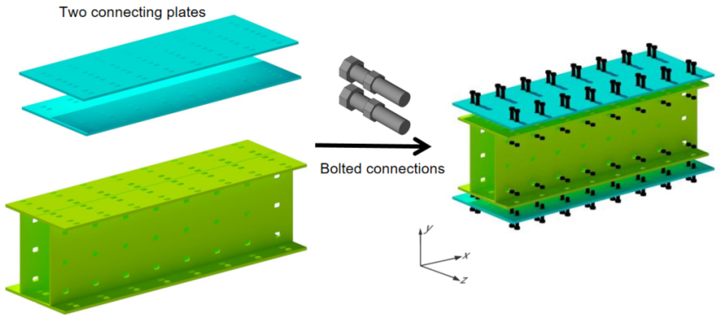
2.1. Specimen Description

The main unit of the prefabricated H-shaped steel beam component consisted of a double-combined HM150 (148 × 100 × 6 × 9 mm) steel section and connecting plates. On both sides of the H-shaped steel component, 9 mm thick connecting plates were installed, which were attached to the H-shaped steel flanges using grade 8.8 M8 bolts, as shown in Figure 1. The direction of the force applied to the steel beam component is along the y-axis, and the Cartesian three-dimensional coordinate system referenced throughout this study adheres to the standard shown in Figure 2. The main unit of the prefabricated H-shaped steel beam component was categorised into different specimens based on the hole sizes of the connecting plates and double-combined HM150 steel sections.

2.2. Experimental Specimens

The geometric parameters of the specimen cross-sections are shown in Figure 3. The height of the T-section formed by the bolt holes in the HM150 steel member is 130 mm, with bolt hole spacing of 40 mm along the height of the main unit of the prefabricated H-shaped steel beam component. The selected specimens consist of prefabricated H-shaped steel beam components with a length of 1.995 m. Along the length of the main unit, the edge distance of the bolt holes is 47.5 mm, and the spacing between the bolt holes is 100 mm. The connection plates are made of 9 mm thick steel, and the stiffening ribs are made of 6 mm thick steel, positioned 80 mm from both ends and at the mid-span of the component. Along the length of the main unit of the steel beam, the bolt hole edge distance is 47.5 mm, and the bolt hole spacing is 100 mm. Five specimens were fabricated with assembly joints located at the centre of the bolt holes in the plates. The specimen numbering scheme was based on the hole pattern in the connection plates and HM150 steel section. For example, in the designation “BL15 × 9-HC9”, “B1” represents the connection plate, “L” indicates a long slot hole, and “9 × 15” specifies the size of the long slot hole. The “H” stands for HM150 steel, “C” denotes a circular hole, and “9” indicates the diameter of the standard circular hole. The construction of the specimens is illustrated in Figure 3, and the design parameters of the assembly joints for each specimen are listed in Table 1.
The specimen fabrication process is illustrated in Figure 4. Holes were created in the H-shaped steel and connection plates using laser cutting machines. After the cutting process, the rust on the steel surface around the cutting areas was removed and the surfaces were wiped with acetone to eliminate grease. The specimens were then assembled using high-strength bolts. To prevent variations in the bearing capacity of the specimens caused by discrepancies in the bolt pre-tightening force, a torque wrench was used during the installation process with a specified installation torque of 16 NM.

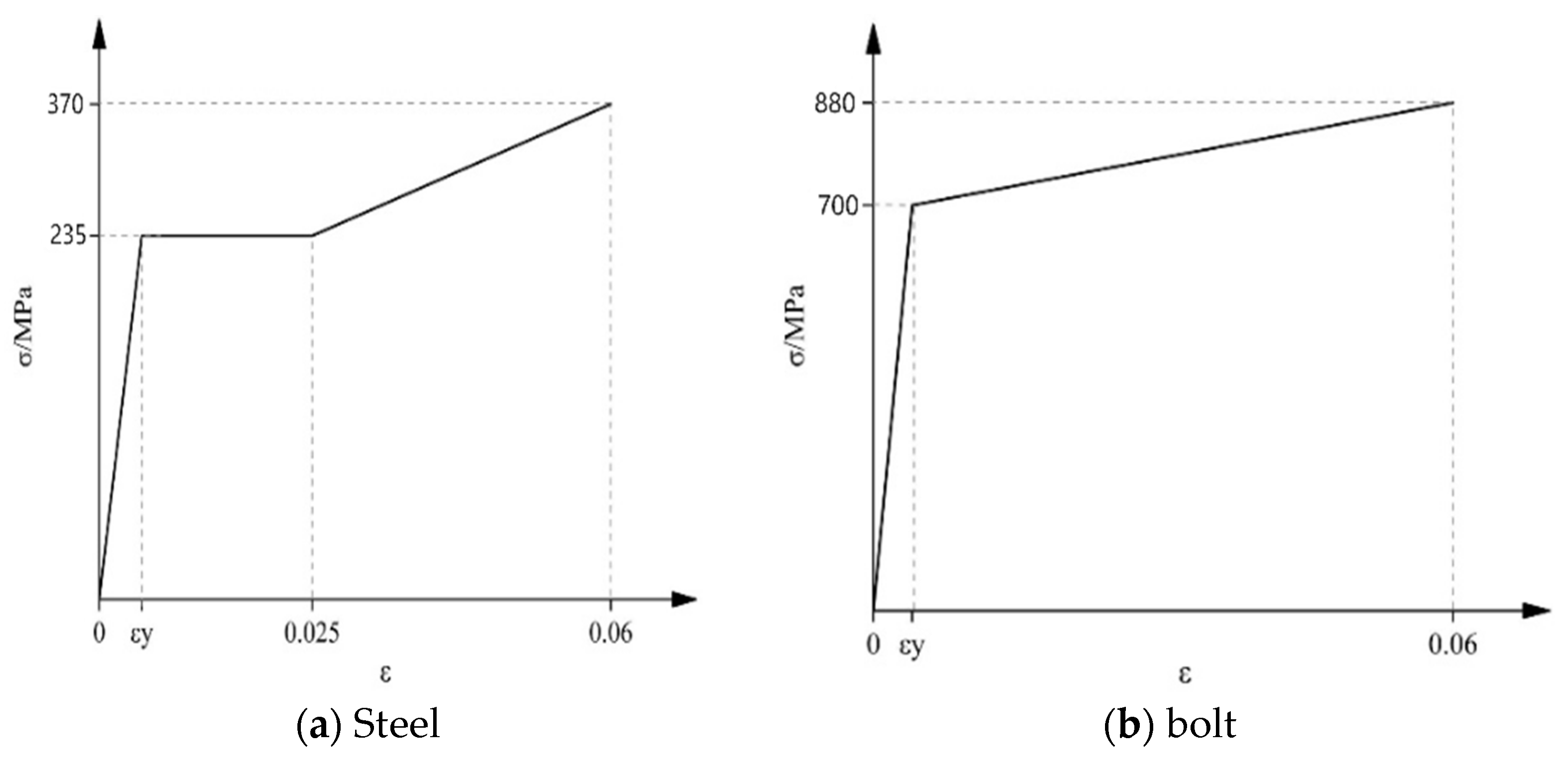
2.3. Material Properties

Specimens were fabricated using Q235-grade cold-rolled steel plates. Tensile coupon tests were performed to determine the material properties of the specimens. According to the recommendations of GB/T 228.1 [30], material property samples were obtained from the connection plates, stiffening connection plates, and H-shaped steel sections. The selected samples and rolled materials were sourced from the same steel batch. Three samples were obtained from each location, resulting in three groups of nine samples with different material properties. The dimensions of the material property samples, testing apparatus, and test data are presented in Figure 5 and Table 2.

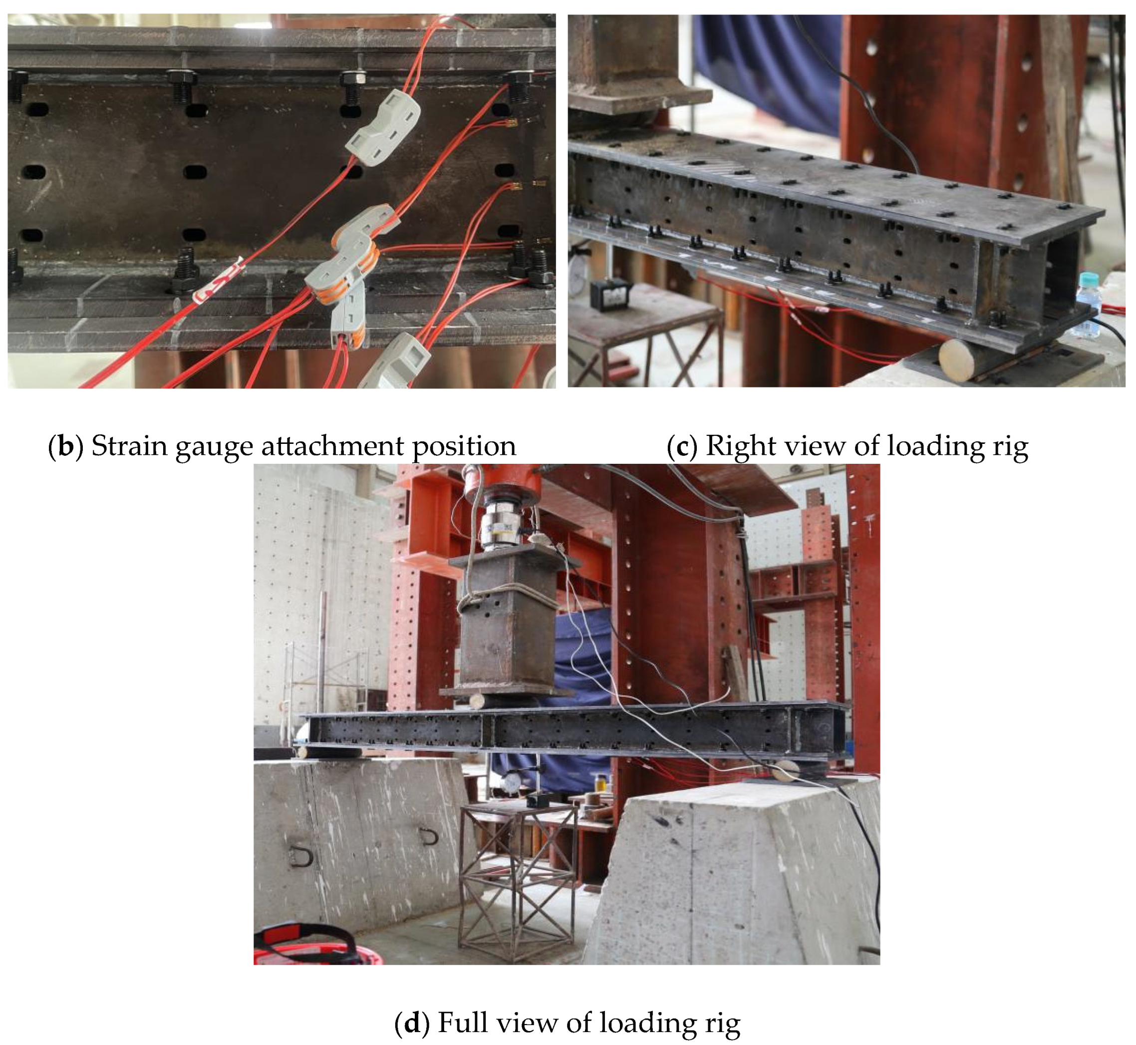
2.4. Testing Apparatus and Measurement System

A three-point bending test was conducted using a high-precision hydraulic jack to apply the load; both the testing procedures and data processing adhered to the GB/T 1041 standard [31], as illustrated in Figure 6. The specimen was supported by a hinge on the left side and a fixed support on the right side, with a displacement transducer positioned at the mid-span. At the beginning of the experiment, a uniform loading rate of 20 kN per stage was applied at the mid-span of the composite beam. During the tests, a high-precision hydraulic jack simultaneously recorded the load and relative displacement at the bottom of the composite steel beam. When the displacement at the mid-span increased at a significantly faster rate than the load, the loading rate was adjusted to 10 kN.
It is evident from summarising previous research [32] that the loading process was terminated upon the occurrence of any of the following phenomena: fracture of the high-strength bolts, tearing of the connected cover plates or end plates, steel components entering a state of noticeably large deformation, local buckling at the loading point of the H-shaped steel section, or any other unexpected occurrence. Seven transverse strain gauges were installed along the vertical height of the beam at the mid-span to measure the strain variations during the loading process. The data acquisition system automatically captured and recorded strain data throughout the entire experiment.

2.5. Experimental Results

2.5.1. Experimental Observations

Table 3 summarises the specific failure modes and ultimate bending moments of the specimens. Taking specimen BC9-HL12 × 9 as an example, no abnormal phenomena were observed before the vertical load at the mid-span reached 240 kN. The real-time displacement–load relationship exhibited good linearity, indicating that the specimen remained in the elastic phase with no significant slip between the components. As the load increased to 250 kN, bolt slip sounds were heard, and slip between the H-shaped steel and connection plates began. And at this point, the mid-span displacement no longer maintains a linear relationship with the applied load. The slip in the upper section was slower than that in the lower section, likely because the tensile region at the bottom of the mid-span entered the plastic stage first, where the prying forces of the bolts constrained the relative slip, leading to a nonlinear slip response in the section.
As the load continued to increase to 420 kN, significant slip occurred at the bottom of the specimen, and the slip at the upper section increased to some extent. Noticeable plastic deformation occurred at the loading point, making further loading difficult, with even small increments in the load causing large vertical displacements. When the load reached 426 kN, the steel plate around the bolt hole on the lower flange of the mid-span H-shaped steel section fractured.

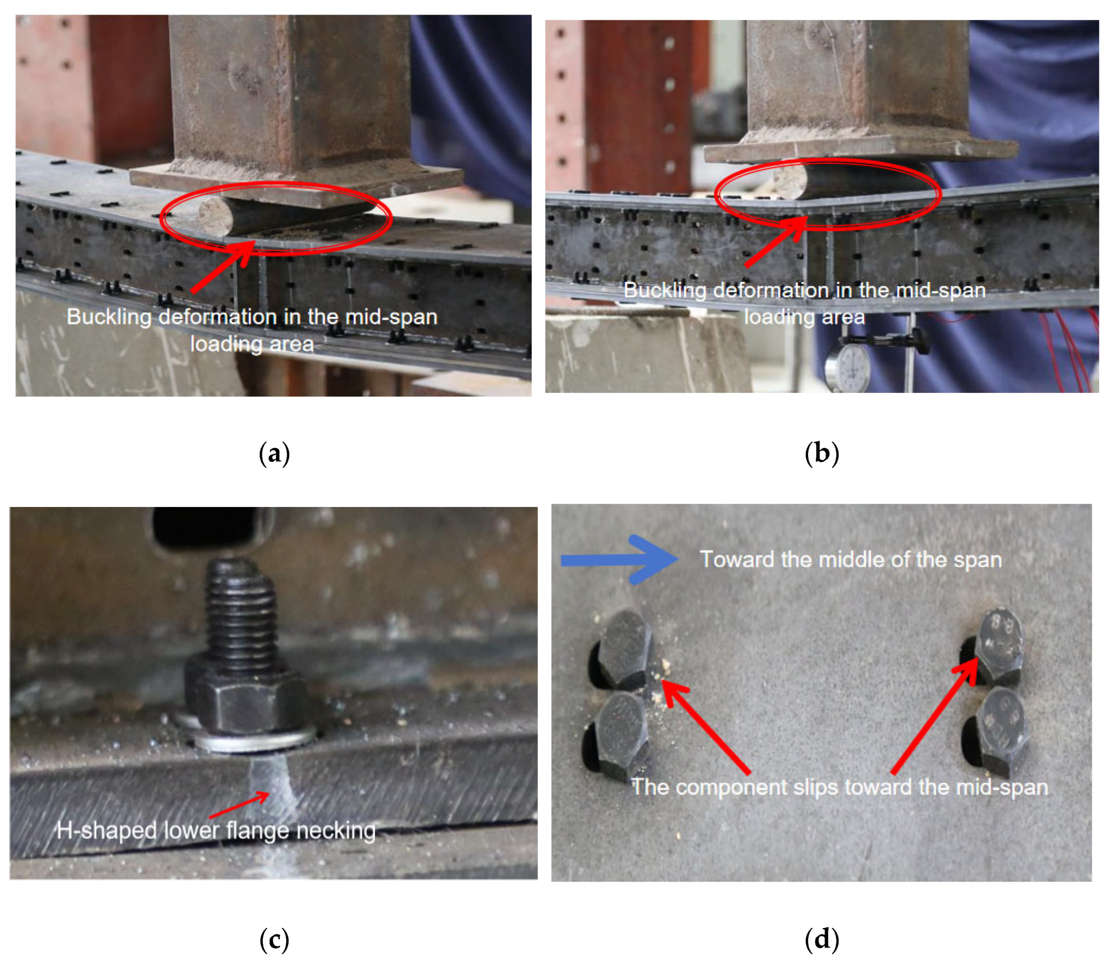
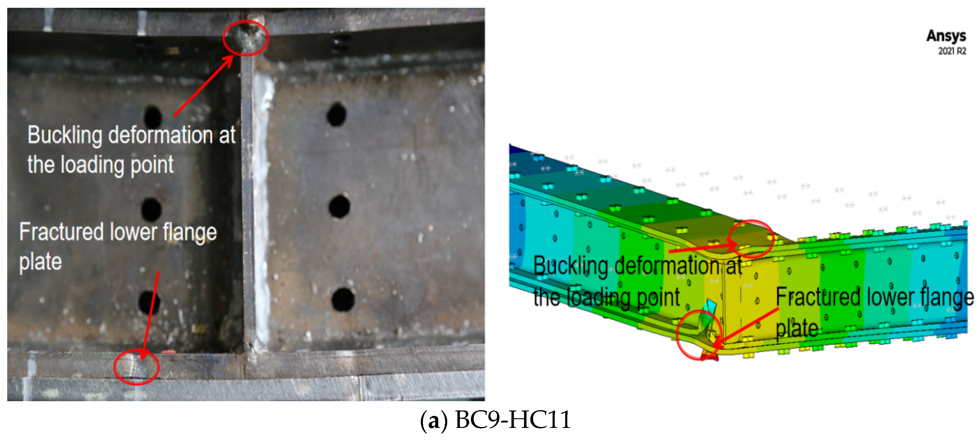
2.5.2. Failure Modes

The primary failure phenomenon observed during the three-point bending test was buckling deformation at the mid-span of the H-shaped steel section (Figure 7). Based on the condition of the lower flange at the point of failure, the failure modes were further categorised as flange plate failure (labelled as FF-L) and flange plate fracture (labelled as FF-B). This type of failure indicates that the maximum stress in the specimens occurred around the bolt holes, where the stress concentrations were induced by the bolt hole openings. The localised stress at these bolt holes exceeded the bending capacity of the H-shaped steel section, resulting in redistribution of the plastic stress. Eventually, the entire section reaches its bending strength, leading to specimen failure.
All cases of flange plate failure occurred in specimens with long slot holes of 9 × 15 mm in the H-shaped steel section, whereas specimens with shorter long slot holes and other circular hole configurations experienced flange plate fracture. This phenomenon can be attributed to the increasing mid-span deflection during loading, which caused a relative slip between the components on both sides of the mid-span (Figure 8). The bolts disrupted the load transfer mechanism, which relied solely on friction, resulting in a loss of pre-tensioning force. Ultimately, the long slot hole specimens failed to reach flange plate fracture.

3. Mechanical Behaviour of Prefabricated Double-H-Shaped Steel Components

3.1. Mid-Span Load–Deflection Relationship

The bending moment versus deflection curves for the prefabricated double H-shaped steel specimens at the mid-span are shown in Figure 9. Mid-span deflection data were obtained from displacement transducers installed at the mid-span during the tests. The overall deformation of the perforated specimens can be divided into three stages.
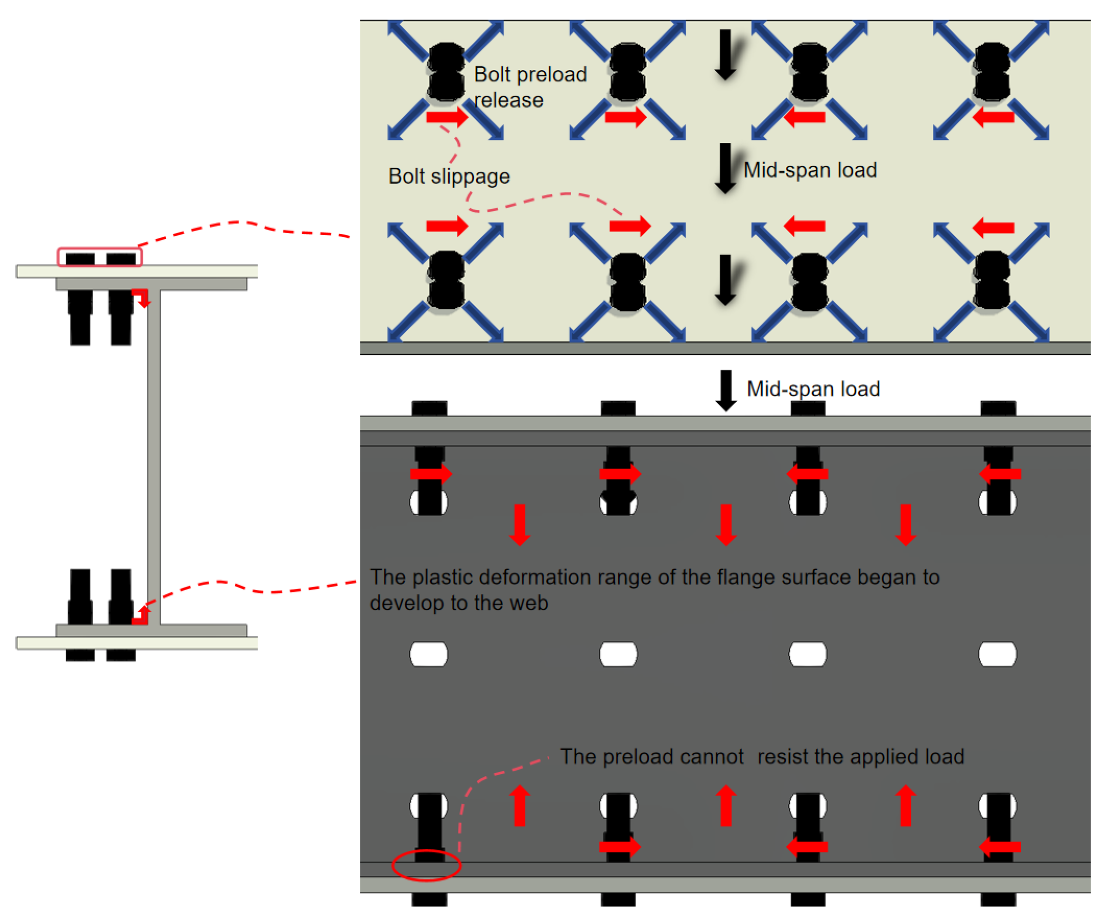
  • Stage 1: Linear increase in the moment–deflection curve: As the load was incrementally applied, the mid-span deflection of the specimens increased linearly with the load. This linear relationship characterises the initial behaviour of the moment–deflection curves of all specimens. During this stage, the incremental deflection at the mid-span was relatively small, indicating that a pre-tightening force of the bolts was applied during specimen preparation. The bolt heads and nuts compress the H-shaped steel flanges and connection plates, generating static friction, and the applied pre-tension increases the frictional resistance between the components, ensuring a tight connection between the structural elements, thus resisting relative slip under bending moments. At the end of this stage, the H-shaped steel components remained in the elastic phase, and no significant relative slip was observed on either side of the mid-span.
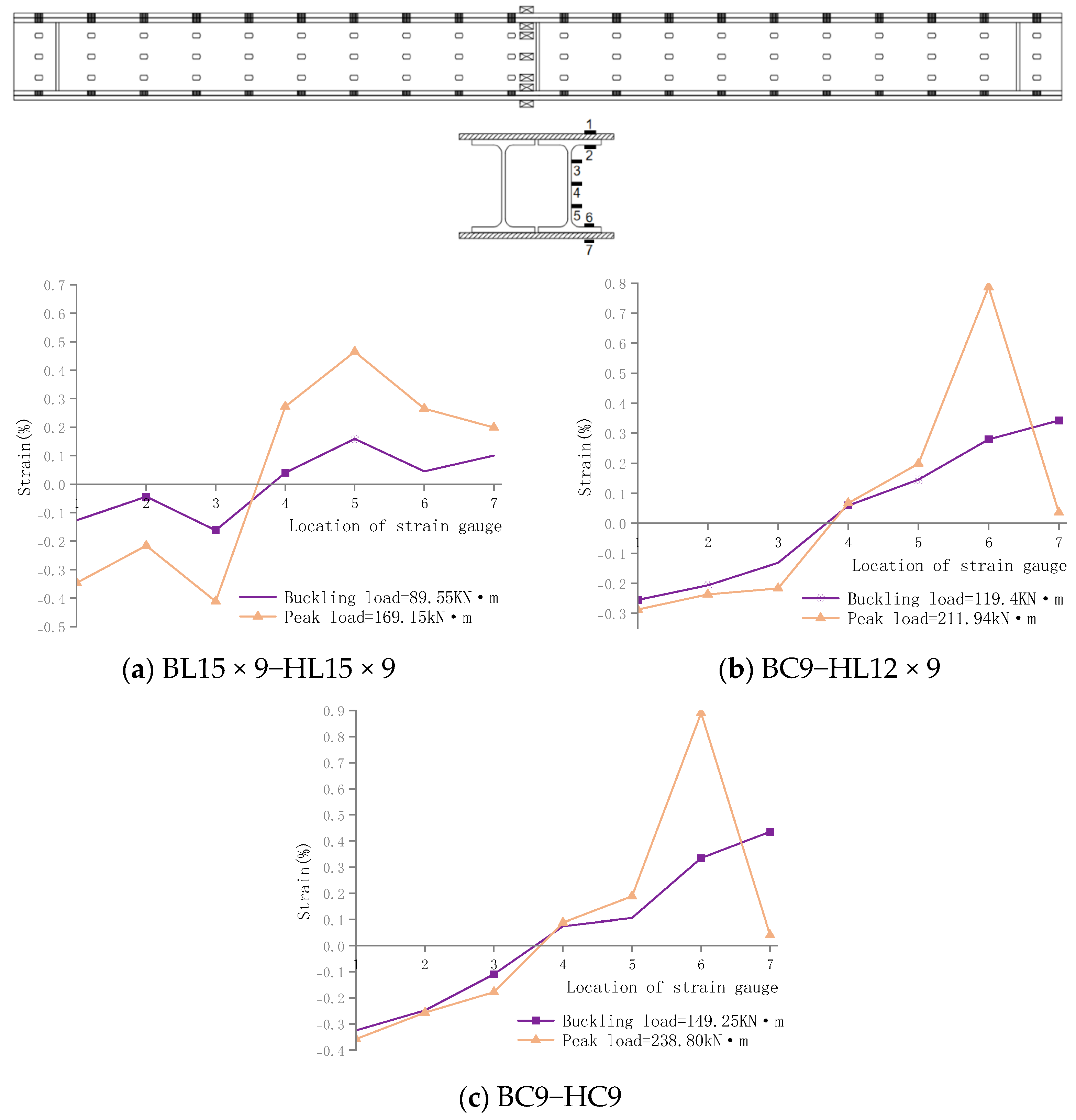
  • Stage 2: Nonlinear increase in the moment–deflection curve: In this stage, as the load continued to increase, the stress in the bolts could no longer accommodate the deformation, and the force distributed to the tensioned steel plates continuously increased. When the distributed force exceeded the shear force generated by the pre-tightening of the bolts, slippage occurred. The root cause is that the frictional resistance provided by the pre-tension is insufficient to counteract the applied load. At this point, most of the load was borne by the bolts on both sides of the mid-span. Because of the smaller moment of inertia of these bolts, the slope of the load–displacement curve decreased. Therefore, during the yielding phase of the specimens, the rate of the deflection increase at the mid-span was significantly higher than that of the load increase. This phase was also accompanied by the yielding and hardening of the double-H-shaped steel components. A distinct inflection point (Point A) can be observed in the moment–deflection curves of specimens FF-L and FF-B, as shown in Figure 9c. The elastic limit bending moment and deflection at this point were recorded as Me and Dy, respectively. During this stage, the bolts on both the upper and lower flanges began to slip toward the mid-span, and the holes in the web of the H-shaped steel exhibited downward tensile deformation as the deflection increased. This indicated that the local plastic deformation at the bolt holes began to propagate from the flange surface to the web.
  • Stage 3: Ultimate stage of the specimens: After the yielding and hardening phases, the load reached the ultimate bending moment Mp, and the specimens completed their plastic deformation, with the mid-span displacement reaching the ultimate deflection Su. The specimens that experienced FF-B failure exhibited higher ultimate bending moments, Mp, and ultimate deflections, Su, than those that experienced FF-L failure. This demonstrates the influence of the bolt hole geometry on the bending capacity and ductility of double-H-shaped steel components. Furthermore, differences in the bending capacity and mid-span deflection capability were observed among the specimens with similar failure modes but different configuration parameters, as shown in Figure 9a–c. These differences are discussed in detail below.

3.2. Bending Performance

As shown in Table 3, the ultimate bending moment of the specimens with long slot holes and large circular holes was 11–30% lower than that of the standard circular hole specimen (BC9-HC9). The analysis results demonstrate that larger bolt holes in the main unit of the double H-shaped steel components led to a reduction in the bending capacity of the specimens. The specimen with standard circular holes in the connection plates (BC9-HC9) exhibited a significantly higher failure moment than the specimen with long slot holes in both the connection plates and HM150 steel under the same design parameters.
Comparing specimens BL15 × 9-HL15 × 9, BC9-HL15 × 9, BC9-HC11, and BC9-HL12 × 9, it can be observed that specimens with standard circular holes in the connection plates have higher bending capacity and stiffness than those with long slot holes in the connection plates under the same parameters. Furthermore, a comparison between BC9-HL12 × 9 and BC9-HC11 revealed that specimens with long slot holes in the double H-shaped steel exhibited greater mid-span deflection than those with circular holes in the H-shaped steel, despite having a bending capacity difference of less than 5%.
Based on the experimental results, the elastic limit bending moment Me of the specimens was determined (because the load was applied incrementally, an exact calculation of the elastic limit bending moment was not possible; therefore, the last applied load before the specimen entered the yielding phase was used for the calculation). The corresponding mid-span node displacement in the y-direction was measured for each specimen. Combining these results with the calculation of the mid-span deflection using the principle of superposition for pure bending deformation in the mechanics of materials, the simplified equivalent bending stiffness can be expressed as shown in Equation (1).
ω = M z l 4 E I E I = M z l 4 ω
In the equation, Mz represents the bending moment of the specimen in the elastic phase (N·mm); I represents the moment of inertia of the specimen in the direction of the applied force (mm4); l represents the span length of the specimen, taken as 1995 mm; ω represents the y-direction displacement at the mid-span node of the specimen (mm). The equivalent bending stiffness for the remaining specimens can be found in Table 4.
Table 3 reveals that the failure stiffness of the specimens decreases as the opening size in the H-shaped steel increases, particularly when the connection plate has standard circular holes. When the opening area in the H-shaped steel exceeds the 12 × 9 threshold, the failure mode shifts from local failure to overall failure. However, when the hole size in the connection plates also increases, the reduction in load-bearing capacity is more significant than the impact on failure stiffness, preventing a change in the failure mode.
As listed in Table 4, during the elastic deformation phase of the specimens, the bending stiffness was greater for specimens with standard circular holes in the connection plates, given the same elastic bending moment and consistent web hole parameters in the H-shaped steel. The analysis suggests that a reduced bolt hole diameter in the connection plates increases the contact area between the bolts and connection plates. This allows the bolt pre-tightening force to more effectively limit relative slip between the components, thereby better controlling the overall bending deformation of the specimen. For specimen BC9-HL12 × 9, which exhibits greater bending stiffness than specimen BC9-HC11, the analysis indicates that the larger 11 mm circular holes create a gap between the bolts and the connection plates at various angles, leading to a less effective constraint compared to short slot holes, which do not adequately limit displacement in the x-direction.
In summary, variations in bolt hole configurations can lead to a reduction in the bending capacity and stiffness of the specimens to some extent. Among the specimens with bolted holes, those with standard circular holes in both the connection plates and H-shaped steel exhibited the highest bending capacity and stiffness. For the remaining specimens, considering construction errors on site and ease of installation, the BC9-HL12 × 9 configuration offers a certain cost-effectiveness.

3.3. Strain Analysis

Figure 10 shows the strain measurements for the upper flange, lower flange, and one side of the web for H-shaped steel beams with long slot holes, short slot holes, and standard circular holes during the three-point bending test. The strain measurements were performed under both buckling and peak loads. Tensile strain was defined as positive strain, whereas compressive strain was defined as negative strain. The figure shows that as the load increased from the buckling load to the peak load, the strain distribution shifted from symmetric to asymmetric owing to the varying hole shapes on the left side of the mid-span. For the specimens with long slot holes, the tensile strain at the yield load was similar to that at the peak load. In contrast, for specimens with short slot holes and standard circular holes, there was a significant difference between the tensile strains at the yield and peak loads. The analysis suggests that in the long slot hole specimens, the bolts lose their pre-tightening force owing to slippage during the failure stage, resulting in the tensile yield stress approaching the ultimate tensile stress of the lower flange and steel plate. Meanwhile, the bolts in the short slot holes and standard circular holes provided a shear force to the lower flange of the steel beam, leading to fracture at the lower flange and the formation of a peak curve.
For a detailed analysis of this behaviour, Figure 11 illustrates the mechanism of the long slot hole specimens. As the mid-span load increases, the bolt pre-tightening force begins to release along a diagonal direction. When the vertical displacement caused by buckling at the mid-span becomes sufficiently large, the horizontal component of the bolt pre-tightening force cannot resist sliding along the beam length. Consequently, the bolts on both sides of the mid-span begin to slip toward the mid-span. This leads to a gradual expansion of the local plastic deformation zone around the bolt holes in the z-direction, with plastic deformation spreading from the flange surface toward the web.
Additionally, the distribution of the compressive strain in the upper flange and tensile strain in the lower flange is largely consistent. Because of the introduction of holes in the web, the strain at the neutral axis of the H-shaped steel is not zero, which violates the assumption of a plane section. Moreover, as the size of the holes in the web increases, the nonlinearity of the strain distribution along the web becomes more pronounced.

4. Finite Element Model Validation and Parametric Study

4.1. Finite Element Model Development

To further investigate the impact of hole configurations on the mechanical performance of prefabricated H-shaped steel beam components, the ANSYS finite element analysis software was used to develop models for five specimens with different hole configurations. These models were used to simulate and analyse the buckling behaviour and bending capacity of the experimental specimens. The double-combined HM150 steel, connection plates, and bolts were modelled using Solid Brick 10-node 185 solid elements [33,34,35]. It is able to more accurately simulate material behaviour and structural responses, particularly capturing local effects such as stress concentrations and deformation patterns under complex geometries or loading conditions. Considering the balance between computational accuracy and efficiency, mapped meshing was applied uniformly across all the specimens. The grid size was set to 10 × 10 mm for the double-combined HM150 steel and connection plate elements, and the M8 bolt elements were divided into 5 mm mesh. To ensure accuracy, a mesh refinement was applied around the bolt holes and chamfered areas. The boundary conditions for the simply supported beam model constrained the translational displacement in the X, Y, and Z directions at one end of the model, and the translational displacement in the Y and Z directions at the other end; CONTA174 contact elements were used for the contact surfaces, and the target surfaces were modelled using TARGE170 target elements [36]. The contact stiffness, penetration tolerance, and friction coefficient of the contact surfaces were set as 0.1, 0.01, and 0.35, respectively.
The material behaviour was modelled using a multilinear kinematic hardening (MKIN) elastoplastic model and the von Mises yield criterion was used to predict the yielding of the components (unless otherwise specified, all subsequent references to stress refer to the von Mises stress). The size specifications and mechanical properties of the double-combined HM150 steel were selected according to the Design Code for Steel Structures [37]. The constitutive model for the Q235B steel was defined using a trilinear elastoplastic hardening model, as shown in Figure 12a. The 8.8-grade M8 high-strength bolt shanks and nuts were modelled as equivalent diameter cylinders, with the equivalent diameter selected according to High-Strength Large Hexagonal Head Bolts for Steel Structures [38]. The constitutive relationship of the bolts was defined using a bilinear elastoplastic hardening model, as shown in Figure 12b. The elastic modulus E for both the steel and bolts was set to 2.06 × 10⁵ N/mm2, with a Poisson’s ratio of 0.3.

4.2. Loading Conditions and Failure Modes

The loading conditions were consistent with those of earlier experiments. A pre-tightening force of 16 NM was applied to the 8.8-grade M8 high-strength bolts. To simulate the loading mode of the specimens, bending moments were applied in the XY plane to the nodes on the end faces of the coupled specimens and modelled using MASS21 mass elements. The numerical analysis was performed using step-by-step loading with automatic time increment settings for each subload step. In the first analysis step, the boundary constraints and initial bolt pre-tightening forces were applied. In the second step, a full pre-tightening force was applied to the bolts. In the third step, the pre-tightening force was locked in, and a bending moment was applied until significant deformation occurred in the model. A specimen was considered to have failed if the results no longer converged.
The results of the ultimate bending moment and failure modes obtained using ANSYS are listed in Table 5 and Table 6, respectively. The ratio of the ultimate bending moment of the prefabricated H-shaped steel beam components to the mean value was 1.038, with a corresponding standard deviation (St.Dev) of 0.036. The maximum deviation between the ANSYS-predicted and experimental ultimate bending moments was 8.3%. The maximum y-direction displacement at the ultimate bending moment is 4.1 mm.
The failure modes obtained from ANSYS and the experimental results were compared using specimens BC9-HC11 and BL15 × 9-HL15 × 9 as examples. The results are shown in Figure 13a,c. The comparison indicates that the bending capacity and failure modes predicted by ANSYS closely matched the experimental results, validating the ANSYS model developed in this study. Therefore, the validated ANSYS model could be used for further parametric analyses of the specimens.

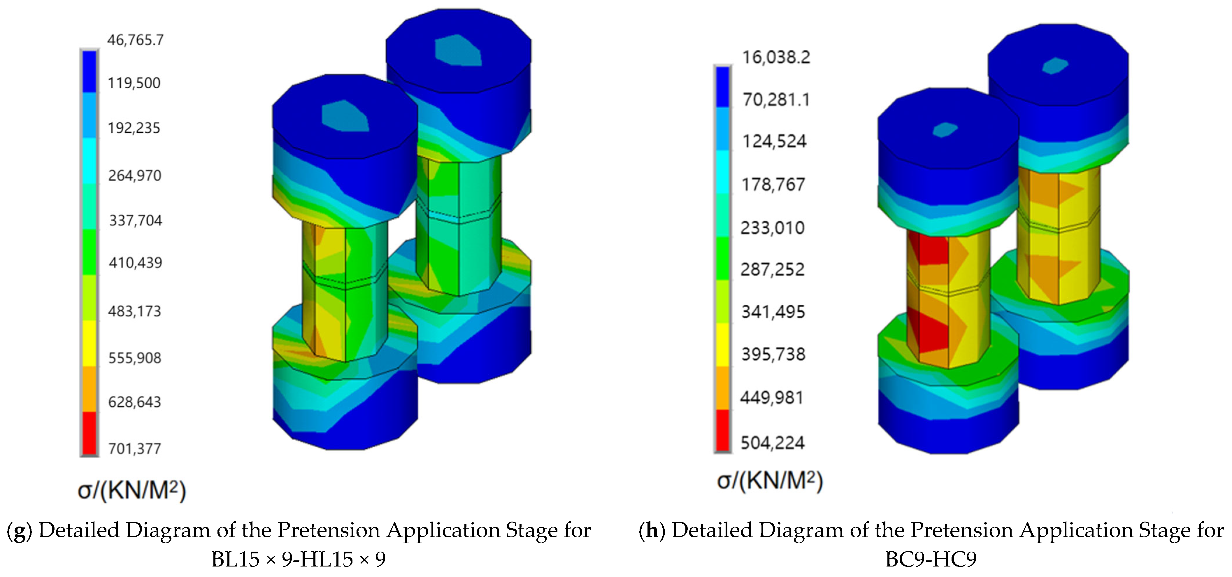
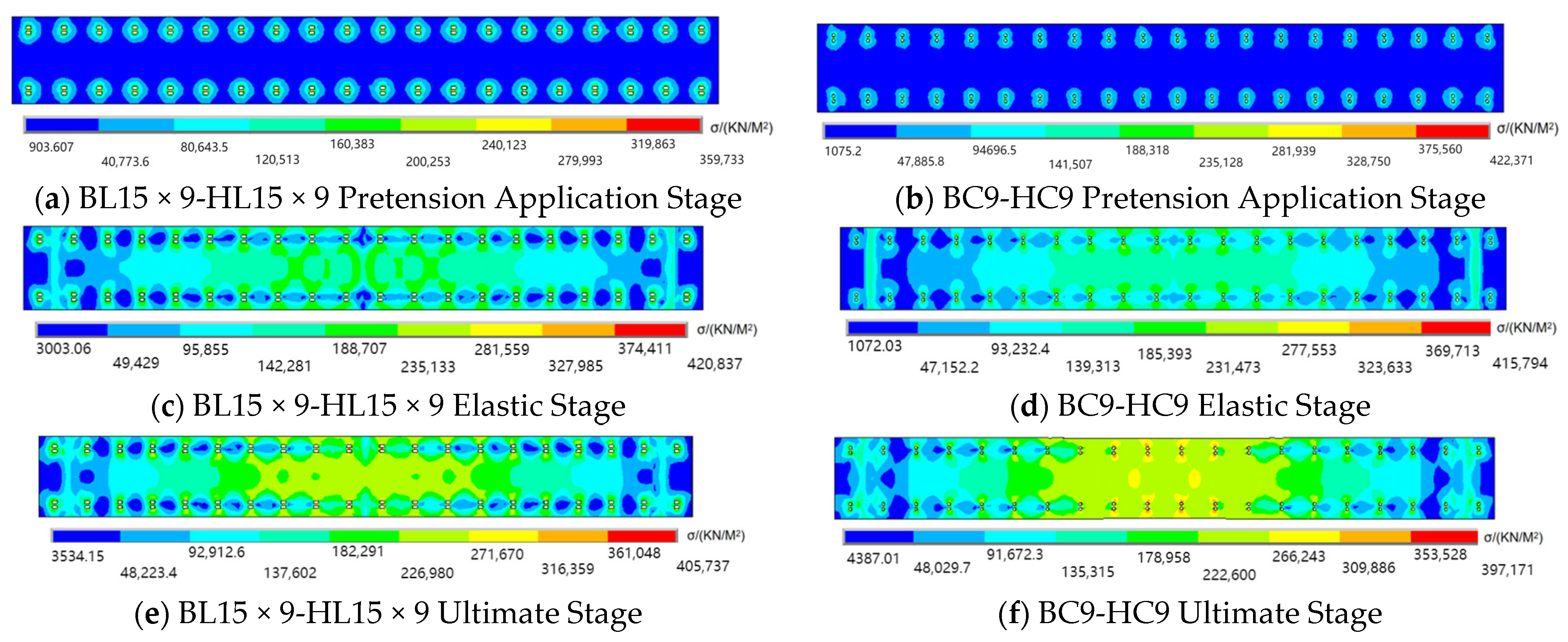
4.3. Analysis of Bolt Pre-Tightening Force

The pre-tightening force of the bolts significantly affects the stability of the connections between components [39]. The preload of the bolts ensures that the structural components remain tightly clamped, providing sufficient frictional resistance to prevent relative movement under applied loads. After the pre-tightening force was applied, the compression of the components under bending moments gradually increased, leading to varying degrees of bolt loosening at different locations. At this point, the compressive force between the components was reduced from the full pre-tightening force to the residual pre-tightening force (F1/kN). The residual pre-tightening forces at the ultimate bending moment of the specimens are shown in Figure 11. UI, UO, LI, and LO represent the average residual pre-tightening forces for the bolts on the inner side of the upper flange, the outer side of the upper flange, the inner side of the lower flange, and the outer side of the lower flange, respectively.
From Figure 14, it is evident that the residual pre-tightening force of the upper flange bolts was significantly greater than that of the lower flange bolts. The loss in the pre-tightening force of the upper flange bolts ranged from approximately 5% to 33%. The compressive stress generated in the upper flange under the bending moment caused the components at the bolt connections to be in a bidirectional compression state. This resulted in only a slight elongation of the bolts owing to the Poisson effect, and ensured that the connection between the components remained highly reliable and tight under the residual pre-tightening force. In contrast, the lower flange bolts experienced a pre-tightening force loss of approximately 65% to 97%. The tensile stress in the lower flange under the bending moment placed the components at the bolt connections in a state of compression in one direction and tension in the other. The compression of the components under load was significant, and the reduction in the bolt length did not compensate for this compression, resulting in bolt loosening.
The residual pre-tightening force of the bolts is linearly related to the ultimate bending moment of the specimens. From the comparison of single-variable specimens BC9-HC9 and BC9-HC11, it can be seen that when the bolt holes in the specimen are circular, the ultimate bending moment of the specimen increases as the hole radius decreases, while the residual pre-tightening force of the bolts decreases. However, for specimen BC9-HL12 × 9, the residual pre-tightening force loss under a higher bending moment is significantly lower than that for single-variable specimen BC9-HL15 × 9. This indicates that when the connection plate has standard circular holes, the bolt connections exhibit higher reliability than those with long slot holes. Therefore, reducing the hole size or increasing the contact area between the connection plate, H-shaped steel, and bolts can reduce the loss of the bolt pre-tightening force and enhance the reliability of the bolt connection.

4.4. Bolt Stress Analysis

For specimen BL15 × 9-HL15 × 9, where both the connection plate and H-shaped steel had long slot holes, the bolt head and nut were only in contact with the component at the long edges of the slot holes. During the application of the pre-tightening force, a very small area at the contact point between the bolt shank and the component reached the yield stress. At this stage, the stress distributions of the bolts in the upper and lower flanges are consistent, as shown in Figure 15a,g, respectively. After the load was applied and the specimen entered the elastic phase, the components relied on the static friction provided by the bolt pre-tightening force to coordinate the forces between them. During this phase, the deformation of the specimen was minimal and the loss of the bolt pre-tightening force was insignificant. The stress distributions in the bolts in the upper and lower flanges remained essentially the same, as shown in Figure 15b.
When the elastic limit bending moment was reached, the specimen entered the yield phase. The compression of the connection plate and the H-shaped steel flange in the compressed region under the bending moment gradually increased. The residual pre-tightening force of the bolts in the compressed region of the upper flange decreased slightly, and the corresponding bolt stress decreased. Simultaneously, the compression of the components in the tensile region began to increase rapidly. As the residual pre-tightening force of the lower flange bolts decreased sharply, the corresponding bolt stress also decreased. Upon reaching the ultimate bending moment, the stress in the lower flange bolts was significantly lower than that in the upper flange bolts, as shown in Figure 15c.
For specimen BC9-HC9, which featured standard circular bolt holes in the connection plates, the contact area between the bolt head and connection plate was larger than that in the long slot hole specimens. During the application of the pre-tightening force, the contact area between the bolt head and the connection plate did not reach the yield stress. However, in the H-shaped steel with long slot holes, a very small area at the contact point between the bolt shank end and component still reached the yield stress, as shown in Figure 15d,h.
After the load was applied, the stress distribution in the bolts followed a pattern similar to that of BL15 × 9-HL15 × 9. However, at the ultimate load stage, buckling deformation in the upper region of BC9-HC9 became more pronounced. The deformation of the standard circular holes caused additional compression on the upper flange bolts, increasing the stress near the bolts, as shown in Figure 15e,f. Because the loss in the pre-tightening force for BC9-HC9 was smaller than that for BL15 × 9-HL15 × 9, the bolt stress under the ultimate bending moment for BC9-HC9 was significantly higher than that for BL15 × 9-HL15 × 9.

4.5. Stress Analysis of the Connection Plates

Under the bending moment generated by the concentrated load, the bolts in the tension zone of the specimens loosened, leading to a more complex stress distribution. However, for the same hole type, the stress distributions in the connection plates of the lower flange were relatively consistent. Therefore, the stress diagrams of the BL15 × 9-HL15 × 9 and BC9-HC9 connection plates at different deformation stages are presented in Figure 11.
Figure 16a,b shows that during the pre-tightening force application stage, the range of influence of the pre-tightening force on the outer bolts of the flange was smaller than that on the inner bolts because of the width limitations of the H-shaped steel flange. Because the hole type BL15 × 9-HL15 × 9 is a long slot, the bolt heads and nuts only make contact with the components at the long edges of the slot, resulting in a slightly more radial distribution of the pre-tightening force influence compared to BC9-HC9.
Figure 16c,d shows that after the specimen entered the elastic phase, the connection plates began to exhibit diagonal high-stress bands along the bolt holes. Once these high-stress areas reach the yield stress, stress redistribution occurs, and the high-stress bands gradually expand outwards. Additionally, in BL15 × 9-HL15 × 9, compared to BC9-HC9, a distinct horizontal low-stress band appeared between the bolt holes along the x-axis direction. This can be attributed to the fact that in the elastic phase, the standard circular holes in the connection plates can maintain a higher level of residual bolt pre-tightening force compared to long slot holes, which helps coordinate the joint force between the connection plates and the H-shaped steel. However, as the mid-span deflection increased, the pre-tightening force loss in the tension zone bolts on both sides increased, preventing the connection plate and H-shaped steel from jointly resisting the tensile force generated by the bending moment. Consequently, the stress phenomenon in regions far from the mid-span became similar for both types of specimens.
Therefore, as shown in Figure 16e,f, after both specimens reached their ultimate stage, the diagonal high-stress bands formed during the elastic phase almost fully developed into full-section yielding near the mid-span. Because the bolts farther from the mid-span were still in the frictional force transfer phase in the ultimate state, horizontal low-stress bands between the bolt holes along the x-axis still existed. Moreover, it can be seen that in both hole types, ultra-high-stress bands are formed in the z-axis direction between the bolt holes at structurally weak points. Thus, under the ultimate bending moment, there was a risk of fracture at these locations.

5. Conclusions

A three-point bending test was conducted to study the effects of different bolt hole types on prefabricated H-shaped steel beams. The results indicate the following:
  • The variation in hole types between the H-shaped steel and connection plates leads to different failure modes, specifically mid-span flange buckling failure and lower flange fracture. The reduction in load-bearing capacity is closely related to the size and location of the holes.
  • The experimental results indicate that the ultimate bending moment capacity of specimens with long slotted holes and large circular holes decreased by 11–30% compared to specimens with standard circular holes. Specimens with standard circular holes demonstrated higher bending capacity and stiffness. Although the difference in bending capacity between double H-shaped steel specimens with long slotted holes and those with circular holes was less than 5%, the former exhibited greater mid-span deflection. Considering construction errors and convenience, the BC9-HL12×9 H-shaped steel beam is a reasonable choice.
  • Prefabricated H-shaped steel beams do not satisfy the plane section assumption. As the area of the web holes increases, the strain distribution in the web becomes more nonlinear. In the long slot hole specimens, the compressive strain distribution in the upper flange and the tensile strain distribution in the lower flange were largely consistent.
  • The ANSYS model was validated for failure modes and bending capacity, followed by a parametric analysis of the bolts and connection plates. The results indicated that the bolt pre-tightening force loss in the compression zone ranged from 5% to 33%, while in the tension zone, it ranged from 65% to 97%, with noticeable bolt loosening in the tension zone. The residual pre-tightening force in the specimens with standard circular holes was higher than that in those with long slotted holes under the same bending moment. Additionally, the connection plates between the z-direction bolt holes in the lower flange of the H-shaped steel were structurally weak, posing a risk of tensile fracture.

Author Contributions

Conceptualisation, X.Z. and D.F.; methodology, X.Z., S.Y., and S.F.; software, D.F. and S.Y.; data curation, S.Y.; data recording, F.Z. and H.C.; preparation of the experiments, F.Z. and H.C.; writing—original draft preparation, S.Y.; writing—review and editing, X.Z. and S.F.; experiment, S.Y., D.F., F.Z., and H.C.; funding acquisition, X.Z. All authors have read and agreed to the published version of the manuscript.

Funding

This research is supported by the Major Scientific & Technological Innovation Projects of Shandong Province (No. 2021CXGC011204). The support is gratefully acknowledged.

Data Availability Statement

Data are not publicly available. The data may be made available upon request from the corresponding author.

Conflicts of Interest

Author Dawei Fan was employed by the company Qihang (Shandong) Investment and Construction Group Co., Ltd. The remaining authors declare that the research was conducted in the absence of any commercial or financial relationships that could be construed as a potential conflict of interest.

References

  1. Huang, Z.; Zhou, H.; Tang, H.; Zhao, Y.; Lin, B. Carbon emissions of prefabricated steel structure components: A case study in China. J. Clean. Prod. 2023, 406, 137047. [Google Scholar] [CrossRef]
  2. Tavares, V.; Soares, N.; Raposo, N.; Marques, P.; Freire, F. Prefabricated versus conventional construction: Comparing life-cycle impacts of alternative structural materials. J. Build. Eng. 2021, 41, 102705. [Google Scholar] [CrossRef]
  3. Paudel, P.; Dulal, S.; Bhandari, M.; Tomar, A. Study on Pre-fabricated Modular and Steel Structures. Int. J. Civ. Eng. (SSRG-IJCE) 2016, 3, 7–14. [Google Scholar]
  4. Chen, Z.; Khan, K.; Khan, A.; Javed, K.; Liu, J. Exploration of the multidirectional stability and response of prefabricated volumetric modular steel structures. J. Constr. Steel Res. 2021, 184, 106826. [Google Scholar] [CrossRef]
  5. Zhou, J.; Li, Y.; Ren, D. Quantitative study on external benefits of prefabricated buildings: From perspectives of economy, environment, and society. Sustain. Cities Soc. 2022, 86, 104132. [Google Scholar] [CrossRef]
  6. Shandong Provincial Highway and Bridge Construction Co., Ltd. Accessories for Enclosure System CN 202120376383.8, 2 November 2021.
  7. American Society of Civil Engineers (ASCE), Specification for the Design of Coldformed Stainless Steel Structural Members, SEI/ASCE 8-02, Reston, Va. 2002. Available online: https://webstore.ansi.org/preview-pages/ASCE/preview_9780784405567.pdf?srsltid=AfmBOoqbuZnHS2jICrnKBIwRizA3uNkITxglkWlmyLd2veVLhyGw3U3S (accessed on 12 June 2024).
  8. Swanson, J.A.; Leon, R.T. Bolted steel connections: Tests on T-stub components. J. Struct. Eng. 2000, 126, 50–56. [Google Scholar] [CrossRef]
  9. Teh, L.H.; Clements, D.D.A. Block shear capacity of bolted connections in cold-reduced steel sheets. J. Struct. Eng. 2012, 138, 459–467. [Google Scholar] [CrossRef]
  10. Feng, R.; Zhan, H.; Meng, S.; Zhu, J. Experiments on H-shaped high-strength steel beams with perforated web. Eng. Struct. 2018, 177, 374–394. [Google Scholar] [CrossRef]
  11. Cavène, E.; Durif, S.; Bouchaïr, A.; Toussaint, E. Experimental study of slotted hole bolted cover-plate connection using full field measurement. In Structures; Elsevier: Amsterdam, The Netherlands, 2020; Volume 23, pp. 573–587. [Google Scholar]
  12. ANSI/AISC 360-22; Specification for Structural Steel Buildings. American Institute of Steel Construction (AISC): Chicago, IL, USA, 2022.
  13. Cristopher, D.M.; Anna, S.; Aaron, V. Experiments on Cold-Formed Steel C-Section Joists with Unstiffened Web Holes. J. Struct. Eng. 2013, 139, 659–704. [Google Scholar]
  14. Pham, D.K.; Pham, C.H.; Pham, S.H.; Hancock, G.J. Experimental investigation of high strength cold-formed channel sections in shear with rectangular and slotted web openings. J. Constr. Steel Res. 2020, 165, 105889. [Google Scholar] [CrossRef]
  15. Fang, Z.; Roy, K.; Chi, Y.; Chen, B.; Lim, J.B. Finite element analysis and proposed design rules for cold-formed stainless steel channels with web holes under end-one-flange loading. In Structures; Elsevier: Amsterdam, The Netherlands, 2021; Volume 34, pp. 2876–2899. [Google Scholar]
  16. Nawar, M.T.; Arafa, I.T.; Elhosseiny, O. Numerical investigation on effective spans ranges of perforated steel beams. In Structures; Elsevier: Amsterdam, The Netherlands, 2020; Volume 25, pp. 398–410. [Google Scholar]
  17. Sangeetha, P.; Revathi, S.M.; Sudhakar, V.; Swarnavarshini, D.; Sweatha, S. Behaviour of cold-formed steel hollow beam with perforation under flexural loading. Mater. Today Proc. 2021, 38, 3103–3109. [Google Scholar] [CrossRef]
  18. Uzzaman, A.; Lim, J.B.; Nash, D.; Roy, K. Web crippling behaviour of cold-formed steel channel sections with edge-stiffened and unstiffened circular holes under interior-two-flange loading condition. Thin-Walled Struct. 2020, 154, 106813. [Google Scholar] [CrossRef]
  19. Degtyareva, N.; Gatheeshgar, P.; Poologanathan, K.; Gunalan, S.; Shyha, I.; McIntosh, A. Local buckling strength and design of cold-formed steel beams with slotted perforations. Thin-Walled Struct. 2020, 156, 106951. [Google Scholar] [CrossRef]
  20. Degtyareva, N.; Gatheeshgar, P.; Poologanathan, K.; Gunalan, S.; Tsavdaridis, K.D.; Napper, S. New distortional buckling design rules for slotted perforated cold-formed steel beams. J. Constr. Steel Res. 2020, 168, 106006. [Google Scholar] [CrossRef]
  21. Wang, X.; Chen, W.; Li, J.; Yang, T. Fire Resistance Performance of Constrained H-Shaped Steel Columns with Uneven Vertical Temperature Distributions. Buildings 2024, 14, 2826. [Google Scholar] [CrossRef]
  22. Weng, Y.; Li, S.; Yuan, X.; Xue, T. Research on Impact Resistance of H-shaped Steel Beam. In Proceedings of the International Conference on Green Building, Civil Engineering and Smart City, Singapore, 15–17 March 2022; Springer NatureSingapore: Singapore, 2022; pp. 1053–1061. [Google Scholar]
  23. Karalar, M.; Dicleli, M. Effect of pile orientation on the fatigue performance of jointless bridge H-piles subjected to cyclic flexural strains. Eng. Struct. 2023, 276, 115385. [Google Scholar] [CrossRef]
  24. Karalar, M.; Dicleli, M. Effect of thermal induced flexural strain cycles on the low cycle fatigue performance of integral bridge steel H-piles. Eng. Struct. 2016, 124, 388–404. [Google Scholar] [CrossRef]
  25. Karalar, M.; Dicleli, M. Fatigue in jointless bridge H-piles under axial load and thermal movements. J. Constr. Steel Res. 2018, 147, 504–522. [Google Scholar] [CrossRef]
  26. Karalar, M.; Dicleli, M. Low-cycle fatigue in steel H-piles of integral bridges; a comparative study of experimental testing and finite element simulation. Steel Compos. Struct. Int. J. 2020, 34, 35–51. [Google Scholar]
  27. Xiao, F.; Zhu, W.; Meng, X.; Chen, G.S. Parameter identification of frame structures by considering shear deformation. Int. J. Distrib. Sens. Netw. 2023, 2023, 6631716. [Google Scholar] [CrossRef]
  28. Xiao, F.; Meng, X.; Zhu, W.; Chen, G.S.; Yan, Y. Combined joint and member damage identification of semi-rigid frames with slender beams considering shear deformation. Buildings 2023, 13, 1631. [Google Scholar] [CrossRef]
  29. Xiao, F.; Zhu, W.; Meng, X.; Chen, G.S. Parameter identification of structures with different connections using static responses. Appl. Sci. 2022, 12, 5896. [Google Scholar] [CrossRef]
  30. GB/T 228.1-2010; Metallic Materials: Tensile Testing: Part 1: Method of Test at Room Temperature. General Administration of Quality Supervision, Inspection and Quarantine of the People’s Republic of China: Beijing, China, 2012.
  31. GB/T 1041-2008; Metallic Materials—Bend Test Method. China Standards Press: Beijing, China, 2008.
  32. Karalar, M.; Dicleli, M. Effect of pile length on the low cycle fatigue performance of integral bridge steel H piles. In Bridge Maintenance, Safety, Management, Life-Cycle Sustainability and Innovations; CRC Press: Boca Raton, FL, USA, 2021; pp. 3888–3891. [Google Scholar]
  33. ANSYS, Inc. 13.185. SOLID185—3D 8-Node Structural Solid; ANSYS Help Documentation; ANSYS, Inc.: Canonsburg, PA, USA, 2024. [Google Scholar]
  34. Sreejith, T.S.; Kaliveeran, V. Stress analysis of a member of jacket structure with different types of stiffeners. In Dynamic Behavior of Soft and Hard Structures; Velmurugan, R., Balaganesan, G., Kakur, N., Kanny, K., Eds.; Springer Nature: Berlin/Heidelberg, Germany, 2024. [Google Scholar]
  35. Mendes, A.C.; Kolodziej, J.A.; Correia, H.J.D. Numerical modelling of wave-current loading on offshore jacket structures. Ships Offshore Struct. 2004, 8, 15–28. [Google Scholar]
  36. Máleková, V.; Jendzelovsky, N. An analysis of contact elements of foundation structures. Int. Virtual J. Sci. Tech. Innov. Ind. 2012, 7, 61–65. [Google Scholar]
  37. GB 50017-2017; Code for Design of Steel Structures. China Architecture & Building Press: Beijing, China, 2018; pp. 22–27.
  38. GB/T 1228-2006; National Technical Committee of Standardization for Fasteners, High-strength Large Hexagon Head Bolts for Steel Structures. Standards Press of China: Beijing, China, 2006; pp. 2–4.
  39. Kong, Q.; Li, Y.; Wang, S.; Yuan, C.; Sang, X. The influence of high-strength bolt preload loss on structural mechanical properties. Eng. Struct. 2022, 271, 114955. [Google Scholar] [CrossRef]
Figure 1. Construction and assembly joints of the prefabricated H-shaped steel main unit. Note: The colours in the diagram distinguish different assembly components.
Buildings 14 02988 g001
Figure 2. Diagram of the construction of the prefabricated H-shaped steel beam main unit and bolt connection. Note: Blue represents the connection plate, green represents the H-beam, and dark gray represents the bolts.
Buildings 14 02988 g002
Figure 3. Schematic diagram of the cross-sectional parameters of the prefabricated H-shaped steel beam component specimen. (a) HM150 Steel Section; (b) Prefabricated H-shaped Steel Beam Component; (c) Side elevation view (using BC9-HC9 as an example).
Buildings 14 02988 g003
Figure 4. Specimen preparation. (a) Hole Drilling; (b) Grinding and Rust Removal; (c) Installation Using Torque Wrench.
Buildings 14 02988 g004
Figure 5. Tensile test of material property specimens. (a) Tensile Specimen for Material Properties; (b) Schematic Diagram of the Tensile Test for Material Properties Specimens.
Buildings 14 02988 g005
Figure 6. Test loading rig.
Buildings 14 02988 g006aBuildings 14 02988 g006b
Figure 7. Failure mode of specimens (FF-L); (a) BL15 × 9-HL15 × 9; (b) BC9-HL15 × 9; (c) H-beam lower flange necking failure; (d) relative slippage between components.
Buildings 14 02988 g007
Figure 8. Failure mode of specimens (FF-B): (a) BC9-HL12 × 9; (b) BC9-HC11; (c) BC9-HC9; (d) BC9-HC9. (d) The lower flange of the H-beam is fractured and damaged.
Buildings 14 02988 g008aBuildings 14 02988 g008b
Figure 9. Mid-span moment–deflection curves of the specimens. Note: (a) shows the curve for the FF-l failure mode; (b) shows the curve for the FF-B failure mode; (c) presents the comparative curves for both failure modes.
Buildings 14 02988 g009
Figure 10. Strain distribution curves. Note: Positions 1–7 correspond to the strain gauge numbering, matching the strain curve numbers in the figure.
Buildings 14 02988 g010
Figure 11. Transfer of forces from mid-span loads in prefabricated H-beams. Note: The red arrows represent the stress transfer path, while the black arrows indicate the application of external loads.
Buildings 14 02988 g011
Figure 12. Constitutive relationship diagram of the computational model.
Buildings 14 02988 g012
Figure 13. Comparison of failure modes between experimental results and ANSYS results.
Buildings 14 02988 g013aBuildings 14 02988 g013b
Figure 14. Residual pretension force diagram of the specimen.
Buildings 14 02988 g014
Figure 15. Cloud diagram of finite element analysis results for the bolt.
Buildings 14 02988 g015aBuildings 14 02988 g015b
Figure 16. Cloud diagram of finite element analysis results for the connection plate.
Buildings 14 02988 g016
Table 1. Design parameters of the specimen assembly joints.
Specimen NameBolt Hole Type of Connection PlateBolt Hole Type of HM150 Steel
BC9-HC99 mm Diameter Standard Circular Hole9 mm Diameter Standard Circular Hole
BC9-HC119 mm Diameter Standard Circular Hole11 mm Diameter Large Circular Hole
BC9-HL12 × 99 mm Diameter Standard Circular Hole9 mm × 12 mm Short Slot Hole
BC9-HL15 × 99 mm Diameter Standard Circular Hole9 mm × 15 mm Long Slot Hole
BL15 × 9-HL15 × 99 mm × 15 mm Long Slot Hole9 mm × 15 mm Long Slot Hole
Table 2. Processing dimensions of material property specimens and material property test results (average value of three coupons).
Specimen IDSampling LocationThickness
/mm
Gauge Length (L0)
/mm
Yield Strength
/MPa
Ultimate Strength
/MPa
Elastic Modulus
/MPa
Elongation
/%
HH-shaped Steel910026039025520.2
BConnection Plate910025539024823.7
LStiffening Rib68024543025619.6
Table 3. Experimental results analysis of specimens under three-point bending.
Specimen NameMp
/(kN·m)
Reduction Factor of Ultimate Moment Capacity for the BC9-HC9 Component
/%
Reduction Factor of Ultimate Moment Capacity for the BC9-HC9 Component
/%
Failure ModeFailure Stiffness
/(kN·m2)
BC9-HC9238.80--78.12FF-B152,460
BC9-HC1119916.6776.5FF-B129,740
BC9-HL12 × 9211.9411.2577.35FF-B136,658
BC9-HL15 × 9175.1226.6765.43FF-L133,487
BL15 × 9-HL15 × 9169.1529.1746.31FF-L182,171
Table 4. Bending stiffness of three-point bending specimens.
Specimen NameBending Moment in the Elastic Phase
/(kN·m)
The Maximum y-Direction Displacement Value of the Bending Moment in the Elastic Phase
/mm
Flexural Stiffness
/(kN·m2)
BC9-HC9149.2511.465,297
BC9-HC11119.410.6456,180
BC9-HL12 × 9119.49.3663,352
BC9-HL15 × 989.555.7078,356
BL15 × 9-HL15 × 989.556.0573,823
Table 5. Comparative analysis of ANSYS finite element simulation results.
SpecimenTest ResultsANSYS ResultsMp/Ma
Mp/(kN·m)Failure ModeMa/(kN·m)Failure Mode
BC9-HC9238.80FF-B218.9FF-B1.091
BC9-HC11199FF-B199FF-B1.000
BC9-HL12 × 9211.94FF-B199FF-B1.065
BC9-HL15 × 9175.12FF-L169.15FF-L1.035
BL15 × 9-HL15 × 9169.15FF-L169.15FF-L1
Mean 1.038
St.Dev 0.036
Note: Mp represents the ultimate moment obtained from experiments, while Ma corresponds to the ultimate moment derived from ANSYS simulations. FF-L indicates failure due to flange buckling control, and FF-B represents the fracture of the lower flange plate governed by buckling control.
Table 6. Analysis of ANSYS finite element simulation results.
Specimen NameComparison of Deviations from the Respective Experimental Ultimate Moments
/%
Reduction Factor of Ultimate Moment Capacity for the BC9-HC9 Component
/%
Maximum
y-Direction Displacement under Ultimate Moment Capacity
/mm
Interpolation of the Maximum y-Direction Displacement for Each Respective Experiment
/mm
BC9-HC98.3--79.13+1.01
BC9-HC11--9.178.79−0.04
BC9-HL12 × 96.19.179.01+2.29
BC9-HL15 × 93.422.766.4+0.97
BL15 × 9-HL15 × 9--22.746.31+4.1
Disclaimer/Publisher’s Note: The statements, opinions and data contained in all publications are solely those of the individual author(s) and contributor(s) and not of MDPI and/or the editor(s). MDPI and/or the editor(s) disclaim responsibility for any injury to people or property resulting from any ideas, methods, instructions or products referred to in the content.

