
Efficacy of IS Code Provisions for Design of Eccentrically Loaded Single Angle Compression Members


Abstract
1. Introduction
2. Design Provisions of IS 800–2007 [26]
3. Design Provisions of IS 800–2007 Amendment 2 [27]
4. Major Changes Incorporated in Amendment 2
- (1)
- It was stated that both flexural-torsional buckling FTB and bending effects were considered in the latest design provisions, contrary to FTB alone considered earlier.
- (2)
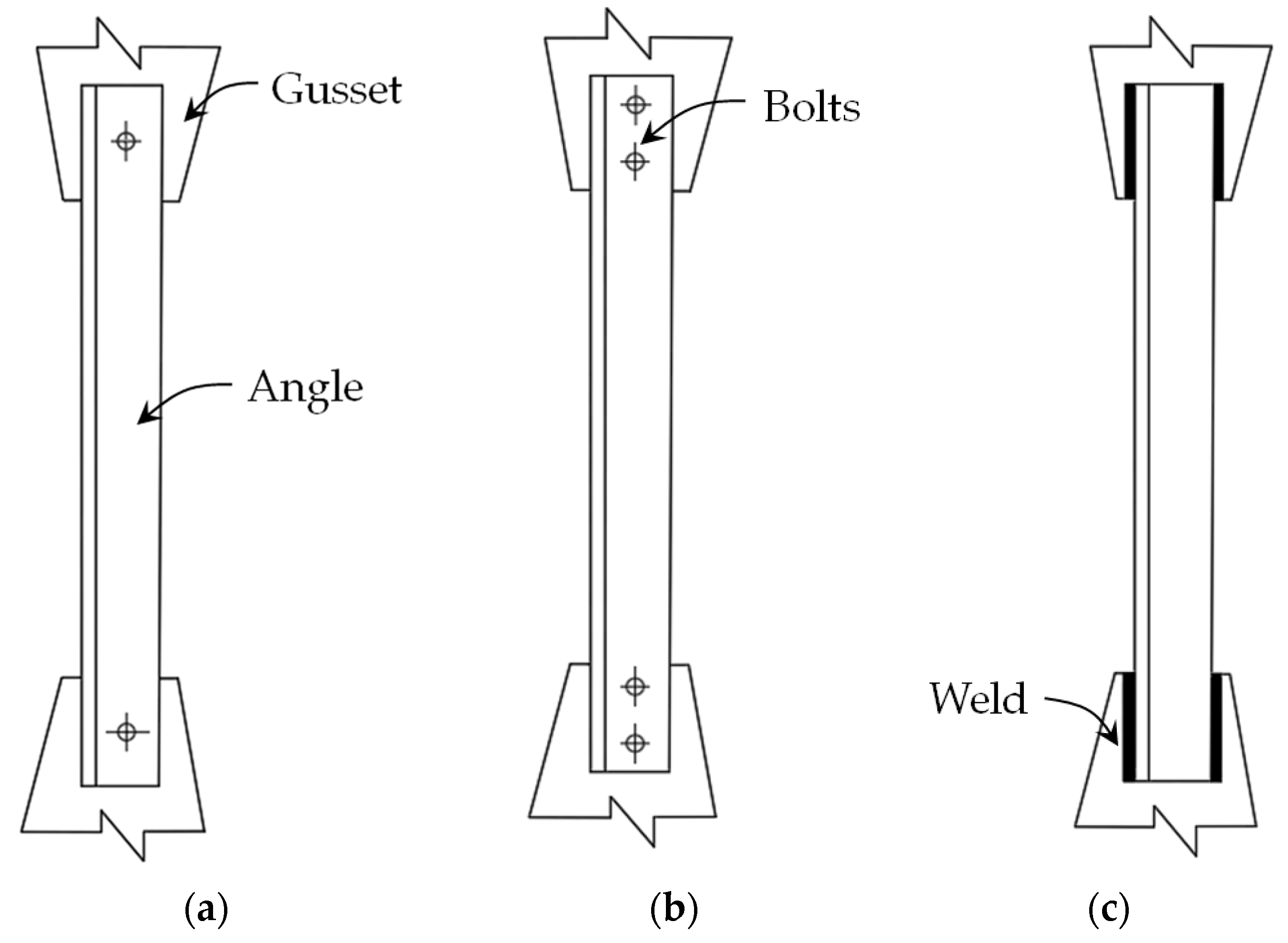
- In the design calculations, the radius of gyration of the minor-principal axis is no longer required, and the emphasis is on the centroidal axis parallel to the connected leg or the plane of end gusset (designated as the a-a axis)—that is, considering out-of-plane buckling (buckling in the direction perpendicular to the plane of the gusset or structural system). Thus, it presumes much greater rotational restraint offered by the restraining member against in-plane buckling i.e., buckling of the angle about axis perpendicular to the plane of gusset [8,29,30]. But, the latest tests [22] reported that in-plane buckling and combined in-plane and out-of-plane buckling were also possible. Based on these experiments and numerical analysis, a new set of equations were proposed to determine the rotational stiffness for both in-plane and out-of-plane buckling [31,32,33,34].
- (3)
- The buckling class has been upgraded from curve ‘c’ to ‘b’, thereby resulting in a lower imperfection factor of 0.34 (to that of 0.49 adopted previously, corresponding to buckling class ‘c’), as adopted in EN 1993-1-1: EC3 [35].
- (4)
- A set of new values were presented for constants k1, k2, and k3.
- (5)
- A new modification factor Kf has been introduced, which accounts for the influence of end connection fixity on the slenderness ratios λaa and λϕ.
5. Design Strength Comparison: IS 800–2007 [26] vs. IS 800–2007 (Amendment 2) [27]
6. Nominal Predicted Strengths vs. Test Strengths
6.1. Comparison with Test Strengths Reported by Bhilawe [21]
6.2. Comparison with Test Strengths Reported by Kettler et al. [22]
7. Discussion
- (a)
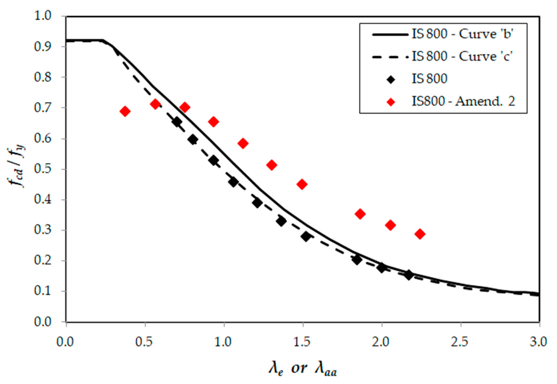
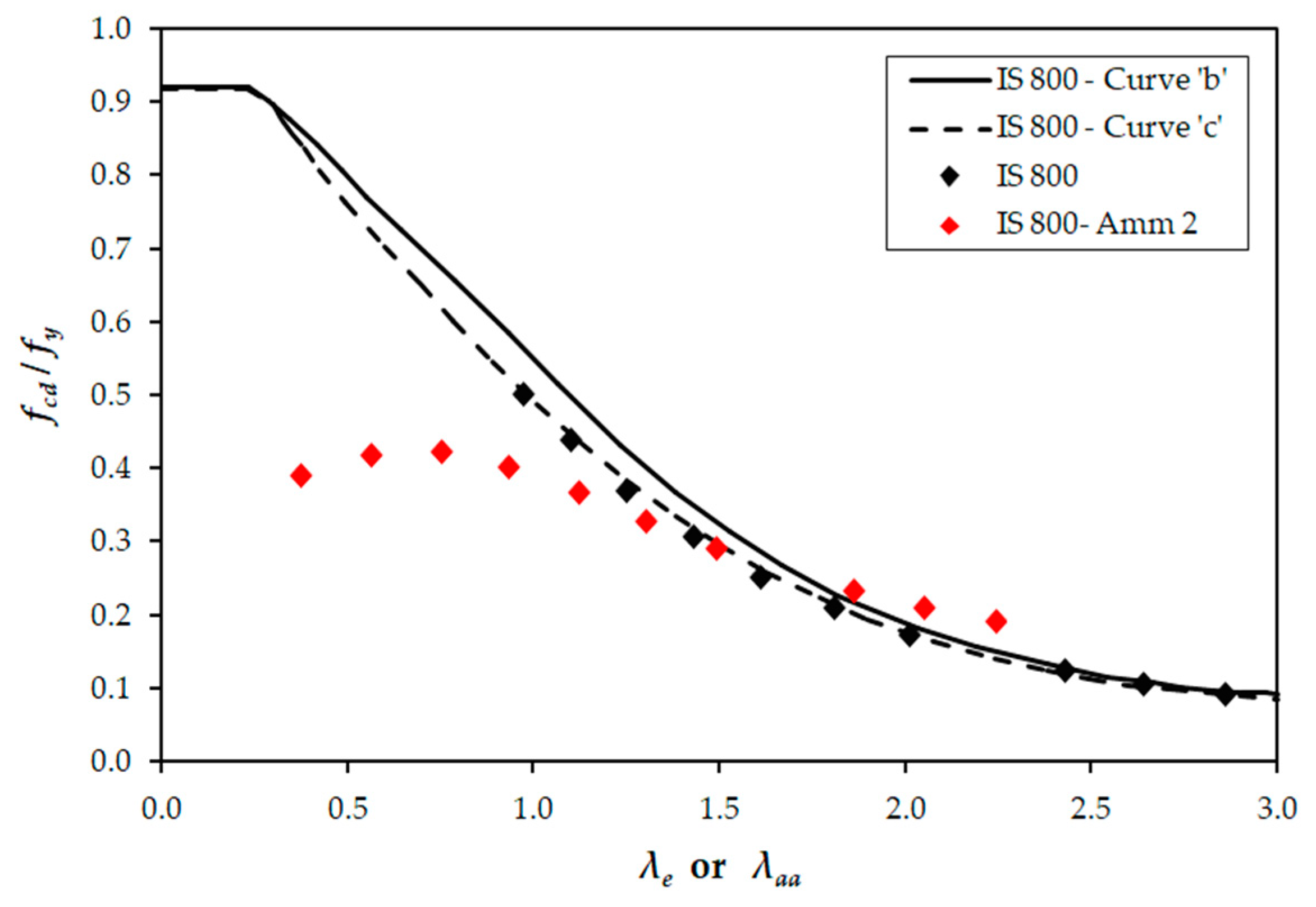
- The design strengths obtained as per the latest provisions [27] were in general much higher in comparison to the corresponding strengths as per earlier provisions [26], except for very few cases of lower column slenderness (Table 4, Table 5 and Table 6). This could be due to the fact that the imperfection factor reduced from 0.49 to 0.34 as the buckling class was changed from ‘c’ to ‘b’ as per Amendment 2 [27] and for cases where Kf > 1.
- (b)
- A maximum rise in axial capacity of 104.84% was noted for the case of two bolts or equivalent weld—hinged connection case, corresponding to a 3.0 m long angle.
- (c)
- (d)
- A single curve cannot be adopted for eccentrically loaded angles. This was also verified based on the experimental and numerical work reported by Kettler et al. [34]. This may be due to the applied load being eccentric to the centroid and only one leg being loaded. The design strength of the end connection and its type, upon which the degree of rotational restraint or fixity depends, also influence the design strength of the angle [32,33].
- (e)
- The equivalent slenderness ratio λe [26] and slenderness ratio about the axis parallel to the connected leg λaa [27] were significantly different for angles with lengths varying from 0.5 m to 1.5 m. However, as the length increased beyond 1.5 m, the difference between the two slenderness ratios narrowed.
- (f)
- An understanding of the implication of updated values for constants k1, k2, and k3 pertaining to end connection fixity and the introduction of new parameter Kf on the design strength is not clear in view of the decreased imperfection factor (refer to (a)).
- (g)
- (a)
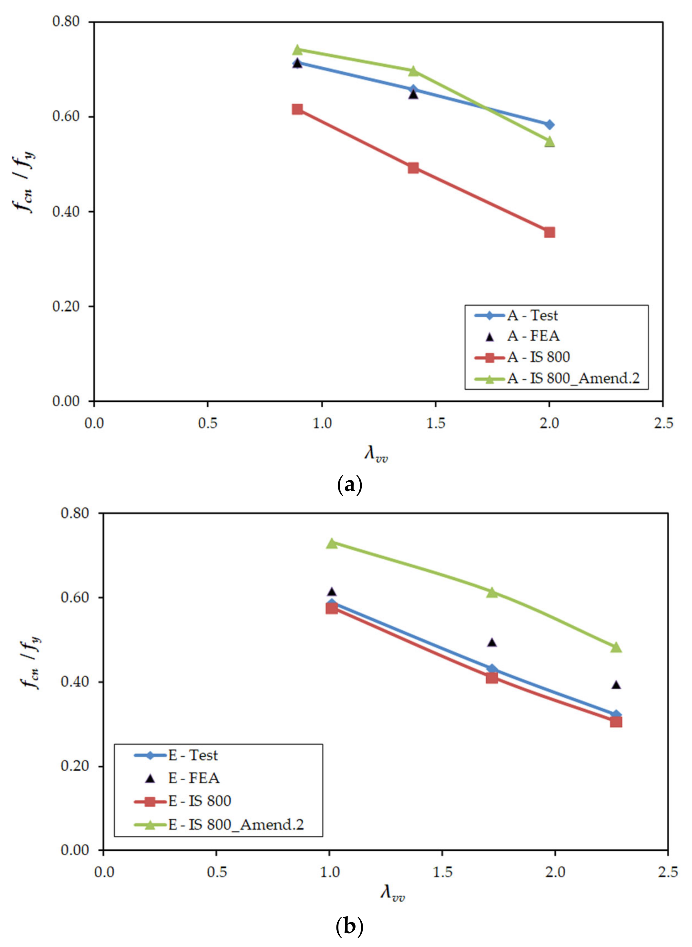
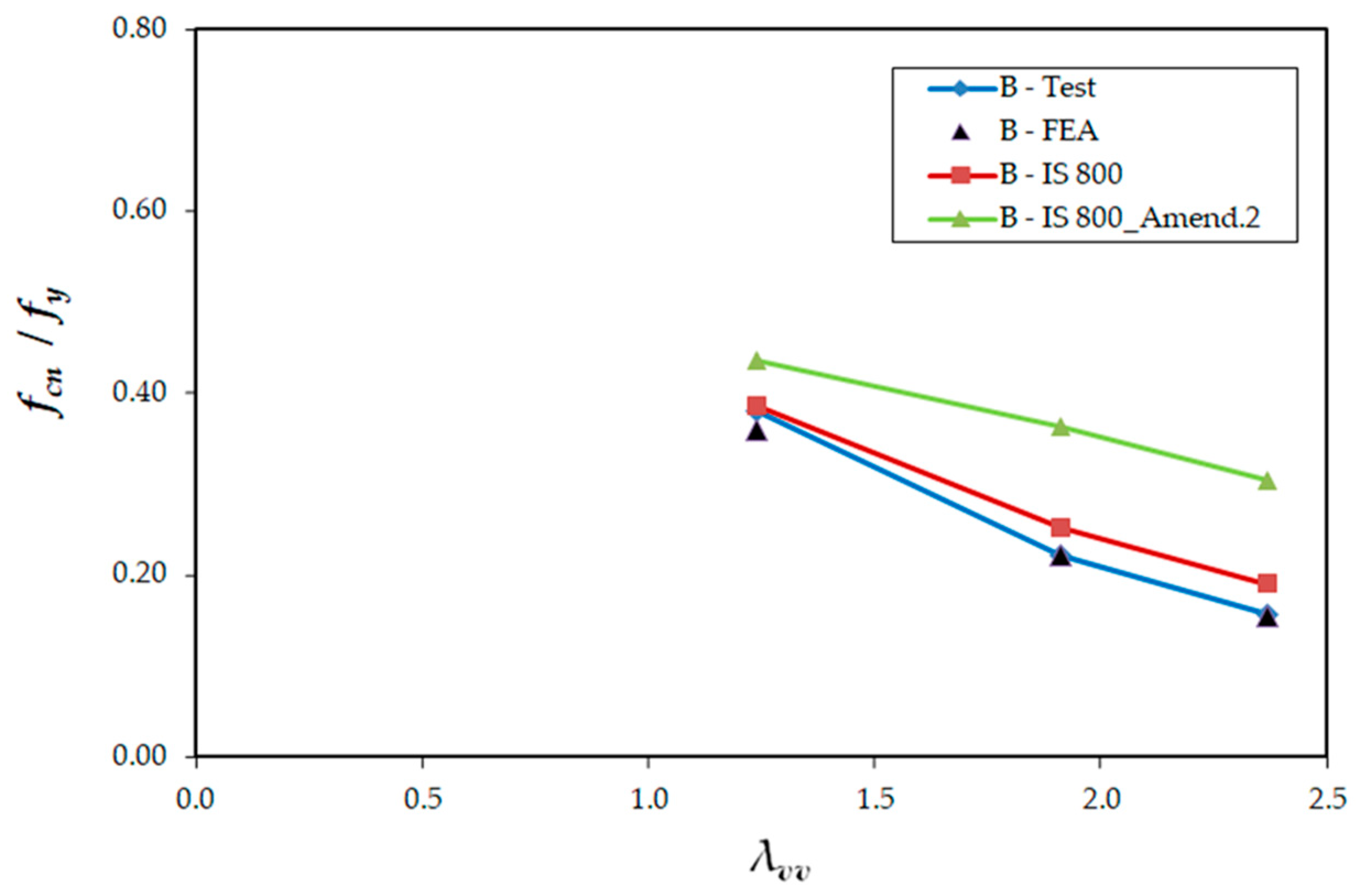
- The nominal strengths obtained as per the latest provisions [27] did not correlate well with the available test strengths (also validated through numerical analysis) [21,22] considered in this study (Table 9, Table 10, Table 11, Table 12, Table 13 and Table 14), though a good agreement was noticed for few cases (for specimens A1, A2, and A3—see Table 11 and Figure 14a).
- (b)
- For the test data set considered, it is observed that the earlier design provisions [26] agreed very well with the test strengths reported in the literature.
- (c)
- Although with a limited test data set, the nominal strengths as per earlier provisions [26] were lower than the test strengths for the majority of cases resulting in a safe and conservative design, whereas it was otherwise in the case of nominal strengths obtained as per the latest provisions [27] (see Figure 12, Figure 13, Figure 14, Figure 15 and Figure 16).
8. Conclusions
- (1)
- The latest design provisions resulted in higher axial capacities, which may lead to smaller cross-sectional sizes.
- (2)
- From the reported results, the latest IS design provisions result in the increase of the design capacity by a maximum of 104.84% (as seen in Table 4) in comparison to the earlier design provisions.
- (3)
- (4)
- However, the latest IS design provisions resulted in very conservative nominal strengths for the one bolt-hinged case (Table 14).
- (5)
- Hence, it is evident that more extensive experimental, numerical, and theoretical investigations have to be carried out considering all the influencing parameters for the accurate and reliable prediction of the axial capacity of eccentrically loaded single angle columns.
Author Contributions
Funding
Data Availability Statement
Conflicts of Interest
References
- Subramanian, N. Design of Steel Structures—Limit States Method, 2nd ed.; Oxford University Press: Noida, India, 2016. [Google Scholar]
- Sai Ram, K.S. Design of Steel Structures, 3rd ed.; Pearson Education: Noida, India, 2020. [Google Scholar]
- Timoshenko, S.P.; Gere, J.M. Theory of Elastic Stability, 2nd ed.; McGraw-Hill: New York, NY, USA, 2009. [Google Scholar]
- Trahair, N.S. Flexural-Torsional Buckling of Structures, 1st ed.; CRC Press Inc.: Boca Raton, FL, USA, 1993. [Google Scholar]
- Yoo, C.H.; Lee, S.C. Stability of Structures—Principles and Applications, 1st ed.; Butterworth-Heinemann: Oxford, UK; Elsevier: New York, NY, USA, 2011. [Google Scholar]
- Sofiani, B.B.; Gardner, L.; Wadee, M.A.; Dinis, P.B.; Camotim, D. Behaviour and design of fixed-ended steel equal–leg angle section columns. J. Constr. Steel Res. 2021, 182, 106649. [Google Scholar] [CrossRef]
- Usami, T.; Galambos, T.V. Eccentrically loaded single angle columns. IABSE Publ. 1971, 31, 153–184. [Google Scholar]
- Woolcock, S.T.; Kitipornchai, S. Design of single angle web struts in trusses. J. Struct. Eng. ASCE 1987, 112, 1327–1345. [Google Scholar] [CrossRef]
- Elgaaly, M.; Dagher, H. Behavior of single-angle-compression members. J. Struct. Eng. ASCE 1992, 117, 3720–3741. [Google Scholar] [CrossRef]
- Bathon, L.; Mueller, W. Ultimate load capacity of single steel angles. J. Struct. Eng. ASCE 1993, 119, 279–300. [Google Scholar] [CrossRef]
- Temple, M.C.; Sakla, S.S.S. Considerations for the design of single-angle compression members attached by one leg. Can. J. Civ. Eng. 1996, 23, 287–294. [Google Scholar] [CrossRef]
- Sakla, S.S.S. Tables for the design strength of eccentrically-loaded single angle struts. Eng. J. AISC 2001, 38, 127–136. [Google Scholar] [CrossRef]
- Sakla, S.S.S. Performance of the AISC LRFD specification in predicting the capacity of eccentrically loaded single-angle struts. Eng. J. AISC 2005, 42, 239–246. [Google Scholar] [CrossRef]
- Earls, E.J.; Keelor, D.C. Toward the simplified design of single-angle beam-columns. Eng. J. AISC 2007, 44, 55–64. [Google Scholar] [CrossRef]
- Yost, J.R.; Dinehart, D.W.; Gross, S.P.; Pote, J.J.; Deeny, J. Buckling strength of single-angle compression members in K-series joists. Eng. J. AISC 2006, 43, 141–152. [Google Scholar] [CrossRef]
- Lutz, L.A. Evaluating single-angle compression struts using an effective slenderness approach. Eng. J. AISC 2006, 43, 241–246. [Google Scholar] [CrossRef]
- Liu, Y.; Hui, L. Behaviour of steel single angles subjected to eccentric axial loads. Can. J. Civ. Eng. 2010, 37, 887–896. [Google Scholar] [CrossRef]
- Chan, S.L.; Cho, S.H. Second-order analysis and design of angle trusses Part I: Elastic analysis and design. Eng. Struct. 2008, 30, 616–625. [Google Scholar] [CrossRef]
- Cho, S.H.; Chan, S.L. Second-order analysis and design of angle trusses Part II: Plastic analysis and design. Eng. Struct. 2008, 30, 626–631. [Google Scholar] [CrossRef]
- Chen, S.; Wang, X. Buckling strength of single angle struts Part 2: Angles connected by one leg at both ends. Adv. Struct. Eng. 2013, 16, 1139–1148. [Google Scholar] [CrossRef]
- Bhilawe, J. Study of equal angle subjected to compression for bolted end connection. J. Inst. Eng. India Ser. A 2017, 99, 123–132. [Google Scholar] [CrossRef]
- Kettler, M.; Lichtl, G.; Unterweger, H. Experimental tests on bolted steel angles in compression with varying end supports. J. Constr. Steel Res. 2019, 155, 301–315. [Google Scholar] [CrossRef]
- Temple, M.C.; Sakla, S.S.S. Single-angle compression members welded by one leg to a gusset plate. I. Experimental study. Can. J. Civ. Eng. 1998, 25, 569–584. [Google Scholar] [CrossRef]
- Temple, M.C.; Sakla, S.S.S. Single-angle compression members welded by one leg to a gusset plate. II. A Parametric study and design equation. Can. J. Civ. Eng. 1998, 25, 585–594. [Google Scholar] [CrossRef]
- Bashar, I.; Amanat, K.M. Comparison of codes for axial compression capacity of eccentrically loaded single angles. J. Constr. Steel Res. 2021, 185, 106829. [Google Scholar] [CrossRef]
- IS 800; Indian Standard General Construction in Steel—Code of Practice. 3rd Revision; BIS: New Delhi, India, 2007.
- IS 800 (Amendment No. 2); Indian Standard General Construction in Steel—Code of Practice. 3rd Revision; BIS: New Delhi, India, 2024.
- IS 808; Hot Rolled Steel Beam, Column, Channel, and Angle Sections—Dimensions and Properties. 4th Revision; BIS: New Delhi, India, 2021.
- Sambasiva Rao, S.; Satish Kumar, S.R.; Kalyanaraman, V. Numerical study on eccentrically loaded hot rolled steel single angle struts. In Proceedings of the Ninth International Conference on Civil and Structural Engineering Computing, Egmond-aan-Zee, The Netherlands, 2–4 September 2003; Topping, B.H.V., Ed.; Civil-Comp Press: Edinburgh, UK, 2003. [Google Scholar] [CrossRef]
- ANSI/AISC 360; Specification for Structural Steel Buildings. AISC: Chicago, IL, USA, 2016.
- Kettler, M.; Unterweger, H.; Zauchner, P. Design model for the compressive strength of angle members including welded end-joints. Thin-Walled Struct. 2022, 175, 109250. [Google Scholar] [CrossRef]
- Kettler, M.; Unterweger, H.; Harringer, T. Appropriate spring stiffness models for the end supports of bolted angle compression members. Steel Constr. 2019, 12, 291–298. [Google Scholar] [CrossRef]
- Kettler, M.; Taras, A.; Unterweger, H. Member capacity of bolted steel angles in compression—Influence of realistic end supports. J. Constr. Steel Res. 2017, 130, 22–35. [Google Scholar] [CrossRef]
- Kettler, M.; Unterweger, H.; Zauchner, P. Design model for bolted angle members in compression including joint stiffness. J. Constr. Steel Res. 2021, 184, 106778. [Google Scholar] [CrossRef]
- EN 1993-1-1: EC3; Design of Steel Structures—Part 1-1: General Rules and Rules for Buildings. European Committee for Standardization: Brussels, Belgium, 2005.


| No. of Bolts at Each end Connection | Gusset/Connecting Member Fixity | k1 | k2 | k3 |
|---|---|---|---|---|
| ≥2 | Fixed | 0.20 | 0.35 | 20 |
| Hinged | 0.70 | 0.60 | 5 | |
| 1 | Fixed | 0.75 | 0.35 | 20 |
| Hinged | 1.25 | 0.50 | 60 |
| End Connection | Gusset/Connecting Member Fixity | k1 | k2 | k3 |
|---|---|---|---|---|
| Fully welded or connected with two or more bolts | Fixed | 0.798 | 0.563 | −2.072 |
| Hinged | 0.401 | 0.420 | −1.040 | |
| Single bolt | Fixed | 0.418 | 0.547 | −1.400 |
| Hinged | 0.374 | 0.415 | −2.072 |
| L (m) | IS 800:2007 [26] | IS 800:2007 Amendment 2 [27] | Pd2/Pd1 | ||||||
|---|---|---|---|---|---|---|---|---|---|
| L/rvv | λe | fcd/fy | Pd1 (kN) | L/raa | λaa | fcd/fy | Pd2 (kN) | ||
| 0.50 | 52.08 | 0.70 | 0.66 | 93.20 | 33.11 | 0.37 | 0.69 | 98.37 | 1.06 |
| 0.75 | 78.13 | 0.80 | 0.60 | 85.15 | 49.67 | 0.56 | 0.72 | 101.62 | 1.19 |
| 1.00 | 104.17 | 0.93 | 0.53 | 75.41 | 66.23 | 0.75 | 0.70 | 100.07 | 1.33 |
| 1.25 | 130.21 | 1.06 | 0.46 | 65.18 | 82.78 | 0.93 | 0.66 | 93.33 | 1.43 |
| 1.50 | 156.25 | 1.21 | 0.39 | 55.53 | 99.34 | 1.12 | 0.59 | 83.50 | 1.50 |
| 1.75 | 182.29 | 1.36 | 0.33 | 47.06 | 115.89 | 1.30 | 0.52 | 73.38 | 1.56 |
| 2.00 | 208.33 | 1.52 | 0.28 | 39.92 | 132.45 | 1.49 | 0.45 | 64.39 | 1.61 |
| 2.50 | 260.42 | 1.84 | 0.21 | 29.21 | 165.56 | 1.86 | 0.36 | 50.64 | 1.73 |
| 2.75 | 286.46 | 2.00 | 0.18 | 25.25 | 182.12 | 2.05 | 0.32 | 45.49 | 1.80 |
| 3.00 | 312.50 | 2.17 | 0.15 | 22.00 | 198.68 | 2.24 | 0.29 | 41.21 | 1.87 |
| L (m) | IS 800:2007 [26] | IS 800:2007 Amendment 2 [27] | Pd2/Pd1 | ||||||
|---|---|---|---|---|---|---|---|---|---|
| L/rvv | λe | fcd/fy | Pd1 (kN) | L/raa | λaa | fcd/fy | Pd2 (kN) | ||
| 0.50 | 52.08 | 0.97 | 0.50 | 71.61 | 33.11 | 0.37 | 0.39 | 55.63 | 0.78 |
| 0.75 | 78.13 | 1.10 | 0.44 | 62.58 | 49.67 | 0.56 | 0.42 | 59.55 | 0.95 |
| 1.00 | 104.17 | 1.25 | 0.37 | 52.87 | 66.23 | 0.75 | 0.42 | 60.29 | 1.14 |
| 1.25 | 130.21 | 1.43 | 0.31 | 43.88 | 82.78 | 0.93 | 0.40 | 57.47 | 1.31 |
| 1.50 | 156.25 | 1.61 | 0.26 | 36.25 | 99.34 | 1.12 | 0.37 | 52.35 | 1.44 |
| 1.75 | 182.29 | 1.81 | 0.21 | 30.05 | 115.89 | 1.30 | 0.33 | 46.48 | 1.55 |
| 2.00 | 208.33 | 2.01 | 0.18 | 25.10 | 132.45 | 1.49 | 0.29 | 41.48 | 1.65 |
| 2.50 | 260.42 | 2.43 | 0.13 | 18.01 | 165.56 | 1.86 | 0.23 | 33.28 | 1.85 |
| 2.75 | 286.46 | 2.64 | 0.11 | 15.48 | 182.12 | 2.05 | 0.21 | 30.14 | 1.95 |
| 3.00 | 312.50 | 2.86 | 0.09 | 13.42 | 198.68 | 2.24 | 0.19 | 27.49 | 2.05 |
| L (m) | IS 800:2007 [26] | IS 800:2007 Amendment 2 [27] | Pd2/Pd1 | ||||||
|---|---|---|---|---|---|---|---|---|---|
| L/rvv | λe | fcd/fy | Pd1 (kN) | L/raa | λaa | fcd/fy | Pd2 (kN) | ||
| 0.50 | 52.08 | 1.02 | 0.48 | 68.01 | 33.11 | 0.37 | 0.42 | 59.32 | 0.87 |
| 0.75 | 78.13 | 1.09 | 0.44 | 62.94 | 49.67 | 0.56 | 0.46 | 65.55 | 1.04 |
| 1.00 | 104.17 | 1.19 | 0.40 | 56.86 | 66.23 | 0.75 | 0.48 | 67.90 | 1.19 |
| 1.25 | 130.21 | 1.30 | 0.36 | 50.46 | 82.78 | 0.93 | 0.46 | 65.87 | 1.31 |
| 1.50 | 156.25 | 1.42 | 0.31 | 44.27 | 99.34 | 1.12 | 0.43 | 60.83 | 1.37 |
| 1.75 | 182.29 | 1.55 | 0.27 | 38.63 | 115.89 | 1.30 | 0.39 | 54.85 | 1.42 |
| 2.00 | 208.33 | 1.69 | 0.24 | 33.65 | 132.45 | 1.42 | 0.35 | 49.18 | 1.46 |
| 2.50 | 260.42 | 1.98 | 0.18 | 25.70 | 165.56 | 1.86 | 0.28 | 40.01 | 1.56 |
| 2.75 | 286.46 | 2.14 | 0.16 | 22.59 | 182.12 | 2.05 | 0.26 | 36.44 | 1.61 |
| 3.00 | 312.50 | 2.29 | 0.14 | 19.96 | 198.68 | 2.24 | 0.24 | 33.40 | 1.67 |
| L (m) | IS 800:2007 [26] | IS 800:2007 Amendment 2 [27] | Pd2/Pd1 | ||||||
|---|---|---|---|---|---|---|---|---|---|
| L/rvv | λe | fcd/fy | Pd1 (kN) | L/raa | λaa | fcd/fy | Pd2 (kN) | ||
| 0.50 | 52.08 | 1.40 | 0.32 | 45.26 | 33.11 | 0.37 | 0.28 | 40.43 | 0.89 |
| 0.75 | 78.13 | 1.47 | 0.29 | 41.48 | 49.67 | 0.56 | 0.32 | 45.55 | 1.10 |
| 1.00 | 104.17 | 1.57 | 0.27 | 37.81 | 66.23 | 0.75 | 0.34 | 47.82 | 1.26 |
| 1.25 | 130.21 | 1.69 | 0.24 | 33.64 | 82.78 | 0.93 | 0.33 | 46.85 | 1.39 |
| 1.50 | 156.25 | 1.82 | 0.21 | 29.63 | 99.34 | 1.12 | 0.31 | 43.59 | 1.47 |
| 1.75 | 182.29 | 1.97 | 0.18 | 25.98 | 115.89 | 1.30 | 0.28 | 39.54 | 1.52 |
| 2.00 | 208.33 | 2.13 | 0.16 | 22.76 | 132.45 | 1.49 | 0.25 | 35.63 | 1.57 |
| 2.50 | 260.42 | 2.46 | 0.12 | 17.55 | 165.56 | 1.86 | 0.21 | 29.20 | 1.66 |
| 2.75 | 286.46 | 2.64 | 0.11 | 15.49 | 182.12 | 2.05 | 0.19 | 26.67 | 1.72 |
| 3.00 | 312.50 | 2.82 | 0.10 | 13.73 | 198.68 | 2.24 | 0.17 | 24.51 | 1.79 |
| Angle | b/t | L/rvv | L/raa | λe | λaa | Pd1 [26] | Pd2 [27] | Pd2/Pd1 |
|---|---|---|---|---|---|---|---|---|
| 45 × 45 × 6 | 7.50 | 172.41 | 111.11 | 1.29 | 1.25 | 45.37 | 69.05 | 1.52 |
| 55 × 55 × 6 | 9.17 | 141.51 | 90.36 | 1.14 | 1.02 | 65.90 | 96.50 | 1.46 |
| 55 × 55 × 8 | 6.88 | 141.51 | 91.46 | 1.10 | 1.03 | 90.14 | 130.91 | 1.45 |
| 60 × 60 × 6 | 10.00 | 130.43 | 82.42 | 1.10 | 0.93 | 75.37 | 108.73 | 1.44 |
| 60 × 60 × 8 | 7.50 | 130.43 | 83.33 | 1.05 | 0.94 | 104.47 | 149.28 | 1.43 |
| 65 × 65 × 6 | 10.83 | 119.05 | 75.76 | 1.06 | 0.85 | 85.47 | 119.90 | 1.40 |
| 65 × 65 × 8 | 8.13 | 120.00 | 76.53 | 1.00 | 0.86 | 119.41 | 166.38 | 1.39 |
| 70 × 70 × 6 | 11.67 | 110.29 | 70.09 | 1.04 | 0.79 | 94.60 | 129.55 | 1.37 |
| 70 × 70 × 8 | 8.75 | 111.11 | 70.75 | 0.97 | 0.80 | 134.29 | 182.48 | 1.36 |
| 75 × 75 × 6 | 12.50 | 102.74 | 65.22 | 1.03 | 0.73 | 102.73 | 138.34 | 1.35 |
| 75 × 75 × 8 | 9.38 | 103.45 | 65.79 | 0.95 | 0.74 | 148.00 | 196.27 | 1.33 |
| 75 × 75 × 10 | 7.50 | 103.45 | 66.37 | 0.90 | 0.75 | 190.11 | 251.23 | 1.32 |
| 80 × 80 × 8 | 10.00 | 96.77 | 61.48 | 0.93 | 0.69 | 160.92 | 208.59 | 1.30 |
| 80 × 80 × 10 | 10.00 | 103.45 | 66.37 | 0.88 | 0.75 | 188.01 | 248.42 | 1.32 |
| 80 × 80 × 12 | 6.67 | 97.40 | 62.76 | 0.86 | 0.71 | 253.62 | 328.29 | 1.29 |
| 90 × 90 × 8 | 11.25 | 85.71 | 54.55 | 0.92 | 0.61 | 184.30 | 229.42 | 1.24 |
| 90 × 90 × 10 | 9.00 | 86.21 | 54.95 | 0.86 | 0.62 | 242.02 | 299.43 | 1.24 |
| 90 × 90 × 12 | 8.33 | 86.21 | 55.35 | 0.82 | 0.62 | 298.31 | 369.01 | 1.24 |
| Angle | b/t | L/rvv | L/raa | λe | λaa | Pd1 | Pd2 | Pd1/Pd2 |
|---|---|---|---|---|---|---|---|---|
| 45 × 45 × 6 | 7.50 | 172.41 | 111.11 | 1.89 | 1.25 | 24.97 | 37.36 | 1.50 |
| 55 × 55 × 6 | 9.17 | 141.51 | 90.36 | 1.78 | 1.02 | 34.1 | 48.57 | 1.42 |
| 55 × 55 × 8 | 6.88 | 141.51 | 91.46 | 1.70 | 1.03 | 48.09 | 68.93 | 1.43 |
| 60 × 60 × 6 | 10.00 | 130.43 | 82.42 | 1.76 | 0.93 | 37.95 | 52.59 | 1.39 |
| 60 × 60 × 8 | 7.50 | 130.43 | 83.33 | 1.66 | 0.94 | 54.57 | 76.29 | 1.40 |
| 65 × 65 × 6 | 10.83 | 119.05 | 75.76 | 1.74 | 0.85 | 41.81 | 55.56 | 1.33 |
| 65 × 65 × 8 | 8.13 | 120 | 76.53 | 1.63 | 0.86 | 61.08 | 82.47 | 1.35 |
| 70 × 70 × 6 | 11.67 | 110.29 | 70.09 | 1.75 | 0.79 | 45.11 | 57.51 | 1.27 |
| 70 × 70 × 8 | 8.75 | 111.11 | 70.75 | 1.62 | 0.80 | 67.35 | 87.61 | 1.30 |
| 75 × 75 × 6 | 12.50 | 102.74 | 65.22 | 1.76 | 0.73 | 47.81 | 58.22 | 1.22 |
| 75 × 75 × 8 | 9.38 | 103.45 | 65.79 | 1.61 | 0.74 | 72.83 | 91.15 | 1.25 |
| 75 × 75 × 10 | 7.50 | 103.45 | 66.37 | 1.53 | 0.75 | 96.59 | 122.55 | 1.27 |
| 80 × 80 × 8 | 10.00 | 96.77 | 61.48 | 1.61 | 0.69 | 77.77 | 93.53 | 1.20 |
| 80 × 80 × 10 | 10.00 | 103.45 | 66.37 | 1.53 | 0.75 | 94.74 | 119.74 | 1.26 |
| 80 × 80 × 12 | 6.67 | 97.40 | 62.76 | 1.48 | 0.71 | 130.00 | 161.48 | 1.24 |
| 90 × 90 × 8 | 11.25 | 85.71 | 54.55 | 1.64 | 0.61 | 86.01 | 95.39 | 1.11 |
| 90 × 90 × 10 | 9.00 | 86.21 | 54.95 | 1.53 | 0.62 | 118.03 | 134.56 | 1.14 |
| 90 × 90 × 12 | 8.33 | 86.21 | 55.35 | 1.47 | 0.62 | 149.63 | 173.41 | 1.16 |
| Specimen | L/rvv | L/raa | (kN) [21] | (kN) [21] | (kN) | (kN) | PTest/PIS800 | PTest/PIS800_Amend.2 |
|---|---|---|---|---|---|---|---|---|
| S2A | 62.17 | 39.53 | 92.5 | 106.32 | 60.95 | 63.03 | 1.52 | 1.47 |
| S2B | 114.56 | 72.83 | 56.23 | 61.12 | 47.77 | 67.10 | 1.18 | 0.84 |
| S2C | 156.25 | 99.34 | 41.62 | 43.82 | 37.80 | 57.41 | 1.10 | 0.72 |
| Mean | 1.27 | 1.01 | ||||||
| Std Dev | 0.22 | 0.40 | ||||||
| COV | 0.18 | 0.40 | ||||||
| Specimen | L/rvv | L/raa | (kN) [21] | (kN) [21] | (kN) | (kN) | PTest/PIS800 | PTest/PIS800_Amend.2 |
|---|---|---|---|---|---|---|---|---|
| S6A | 62.17 | 39.53 | 97.50 | 106.32 | 98.32 | 88.13 | 0.99 | 1.11 |
| S6B | 114.56 | 72.83 | 62.23 | 61.12 | 64.67 | 85.08 | 0.96 | 0.73 |
| S6C | 156.25 | 99.34 | 50.23 | 55.18 | 45.28 | 69.69 | 1.11 | 0.72 |
| Mean | 1.02 | 0.85 | ||||||
| Std Dev | 0.08 | 0.22 | ||||||
| COV | 0.08 | 0.26 | ||||||
| Specimen | L/rvv | L/raa | Bolt Type | (kN) [22] | (kN) [22] | PIS800 (kN) | PIS800_Amend.2 (kN) | PTest/PIS800 | PTest/PIS800_Amend.2 |
|---|---|---|---|---|---|---|---|---|---|
| A1 | 75.23 | 43.07 | Preloaded M20 (10.9) | 261.1 | 261.2 | 225.36 | 271.03 | 1.16 | 0.96 |
| A2 | 118.69 | 76.54 | 238.8 | 235.8 | 179.09 | 253.08 | 1.33 | 0.94 | |
| A3 | 170.35 | 109.88 | 215.4 | 202.2 | 131.89 | 202.41 | 1.63 | 1.06 | |
| D1 | 76.12 | 48.56 | Non-preloaded M20 (10.9) | 260.2 | 273.5 | 220.38 | 277.33 | 1.18 | 0.94 |
| D2 | 172.65 | 109.88 | 177.5 | 204.9 | 120.16 | 191.49 | 1.48 | 0.93 | |
| E1 | 80.42 | 51.78 | Preloaded M27 (10.9) | 488.4 | 512.1 | 479.4 | 607.2 | 1.02 | 0.80 |
| E2 | 136.69 | 87.95 | 357.2 | 409.7 | 341.15 | 509.71 | 1.05 | 0.70 | |
| E3 | 180.26 | 116.60 | 267.1 | 326.8 | 254.26 | 401.19 | 1.05 | 0.67 | |
| Mean | 1.24 | 0.88 | |||||||
| Std Dev | 0.22 | 0.14 | |||||||
| COV | 0.18 | 0.16 | |||||||
| Specimen | L/rvv | L/raa | Bolt Type | (kN) [22] | (kN) [22] | PIS800 (kN) | PIS800_Amend.2 (kN) | PTest/PIS800 | PTest/PIS800_Amend.2 |
|---|---|---|---|---|---|---|---|---|---|
| B1 | 96.11 | 61.32 | Preloaded M20 (10.9) | 148.0 | 140.0 | 150.04 | 169.34 | 0.99 | 0.87 |
| B2 | 148.10 | 94.65 | 86.4 | 85.0 | 97.84 | 141.09 | 0.88 | 0.61 | |
| B3 | 183.97 | 117.28 | 61.0 | 61.6 | 74.33 | 119.32 | 0.82 | 0.51 | |
| Mean | 0.90 | 0.67 | |||||||
| Std Dev | 0.08 | 0.19 | |||||||
| COV | 0.09 | 0.28 | |||||||
| Specimen | L/rvv | L/raa | Bolt Type | (kN) [22] | (kN) [22] | PIS800 (kN) | PIS800_Amend.2 (kN) | PTest/PIS800 | PTest/PIS800_Amend.2 |
|---|---|---|---|---|---|---|---|---|---|
| B4 | 76.12 | 48.56 | Preloaded M20 (10.9) | 162.9 | 165.9 | 169.29 | 184.74 | 0.96 | 0.88 |
| B5 | 120.27 | 76.54 | 132.1 | 140.6 | 138.09 | 183.66 | 0.96 | 0.72 | |
| C1 | 207.06 | 132.1 | 98.4 | 106.1 | 87.04 | 130.22 | 1.13 | 0.76 | |
| D3 | 75.98 | 48.56 | Non-preloaded M20 (10.9) | 154.8 | 150.9 | 166.68 | 182.11 | 0.93 | 0.85 |
| D4 | 207.20 | 132.10 | 73.1 | 89.9 | 82.93 | 124.76 | 0.88 | 0.59 | |
| Mean | 0.97 | 0.76 | |||||||
| Std. Dev. | 0.09 | 0.12 | |||||||
| COV | 0.10 | 0.15 | |||||||
| Specimen | L/rvv | L/raa | Bolt Type | (kN) [22] | (kN) [22] | PIS800 (kN) | PIS800_Amend.2 (kN) | PTest/PIS800 | PTest/PIS800_Amend.2 |
|---|---|---|---|---|---|---|---|---|---|
| C4 | 95.54 | 61.32 | Preloaded M20 (10.9) | 131.0 | 139.3 | 99.34 | 125.78 | 1.32 | 1.04 |
| C5 | 183.65 | 117.28 | 62.6 | 65.0 | 64.91 | 100.29 | 1.00 | 0.65 | |
| D5 | 25.83 | 16.46 | 145.5 | 145.7 | 115.89 | 71.86 | 1.26 | 2.03 | |
| D6 | 35.48 | 22.60 | 151.0 | 151.1 | 114.97 | 82.68 | 1.31 | 1.83 | |
| D7 | 45.31 | 28.81 | 148.8 | 153.4 | 112.51 | 92.03 | 1.32 | 1.62 | |
| D8 | 54.83 | 39.48 | 145.0 | 151.1 | 109.70 | 100.38 | 1.32 | 1.44 | |
| Mean | 1.26 | 1.43 | |||||||
| Std. Dev. | 0.13 | 0.51 | |||||||
| COV | 0.10 | 0.36 | |||||||
Disclaimer/Publisher’s Note: The statements, opinions and data contained in all publications are solely those of the individual author(s) and contributor(s) and not of MDPI and/or the editor(s). MDPI and/or the editor(s) disclaim responsibility for any injury to people or property resulting from any ideas, methods, instructions or products referred to in the content. |
© 2024 by the authors. Licensee MDPI, Basel, Switzerland. This article is an open access article distributed under the terms and conditions of the Creative Commons Attribution (CC BY) license (https://creativecommons.org/licenses/by/4.0/).
Share and Cite
Vivek, S.K.; Dar, M.A.; Narayanan, S. Efficacy of IS Code Provisions for Design of Eccentrically Loaded Single Angle Compression Members. Buildings 2024, 14, 2990. https://doi.org/10.3390/buildings14092990
Vivek SK, Dar MA, Narayanan S. Efficacy of IS Code Provisions for Design of Eccentrically Loaded Single Angle Compression Members. Buildings. 2024; 14(9):2990. https://doi.org/10.3390/buildings14092990
Chicago/Turabian StyleVivek, Sai Kota, Mohammad Adil Dar, and Subramanian Narayanan. 2024. "Efficacy of IS Code Provisions for Design of Eccentrically Loaded Single Angle Compression Members" Buildings 14, no. 9: 2990. https://doi.org/10.3390/buildings14092990
APA StyleVivek, S. K., Dar, M. A., & Narayanan, S. (2024). Efficacy of IS Code Provisions for Design of Eccentrically Loaded Single Angle Compression Members. Buildings, 14(9), 2990. https://doi.org/10.3390/buildings14092990