
Tensile Deformability of Shotcrete in Tunnel Primary Support: A Case Study


 and
and
Abstract
1. Introduction
2. Determination of Tensile Failure Strain of Shotcrete through Laboratory Tests
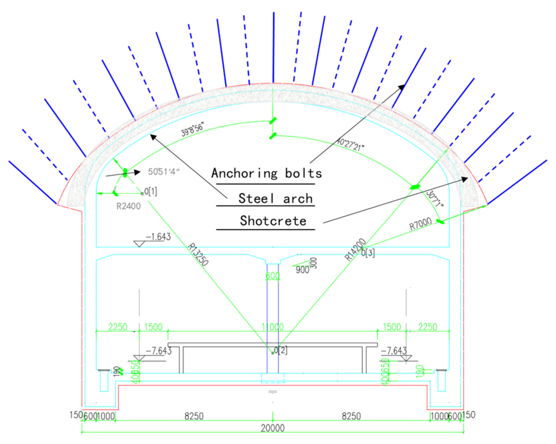
2.1. Engineering Background
2.2. Test Scheme Design
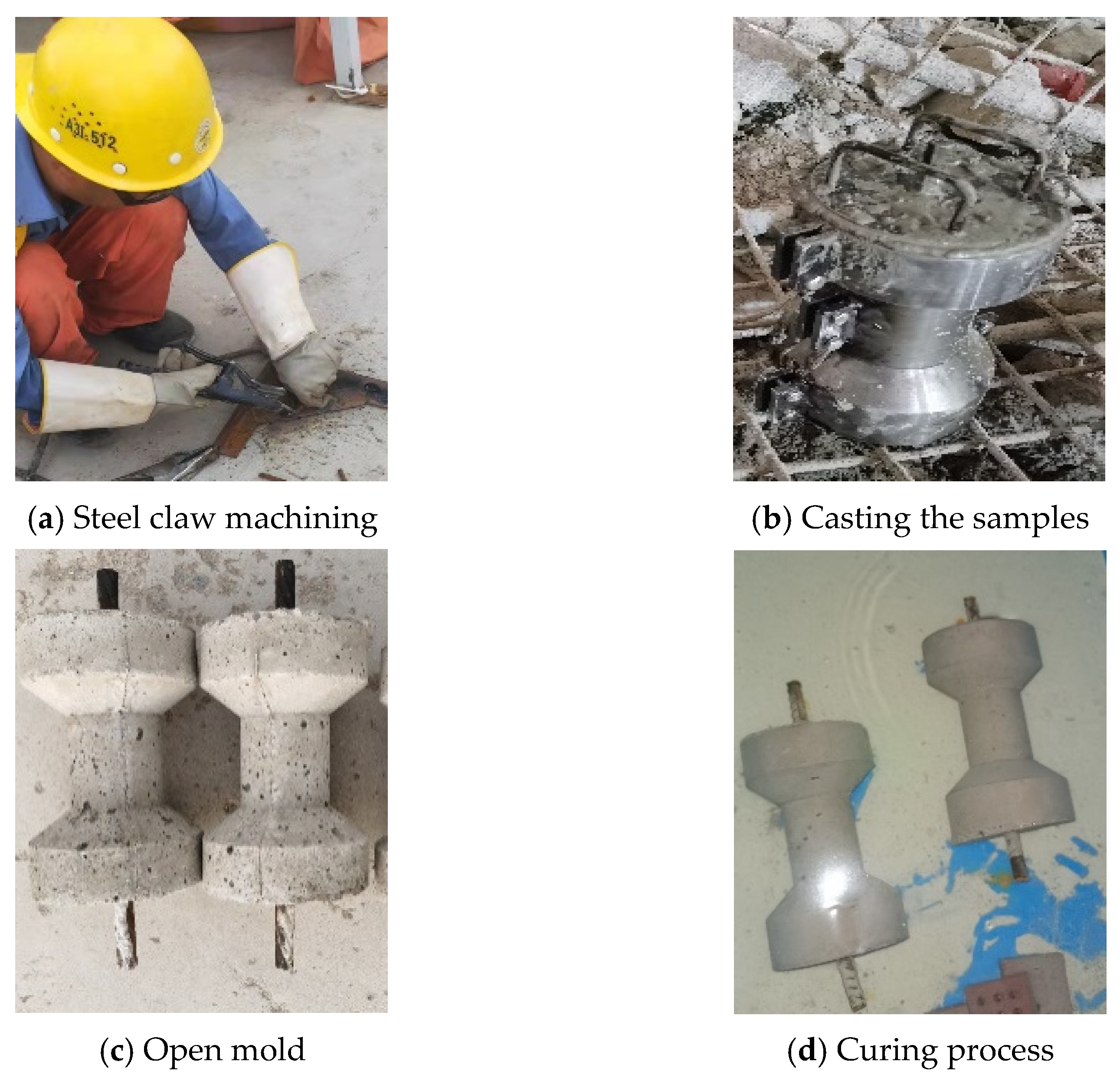
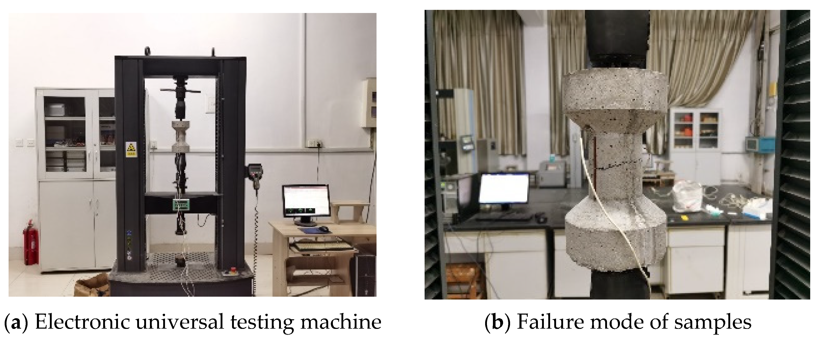
2.3. Test Process
2.4. Analysis of Test Results
3. Field Monitoring Results and Analysis
3.1. Regular Monitoring
3.2. Non-Loading Deformation Test of Shotcrete
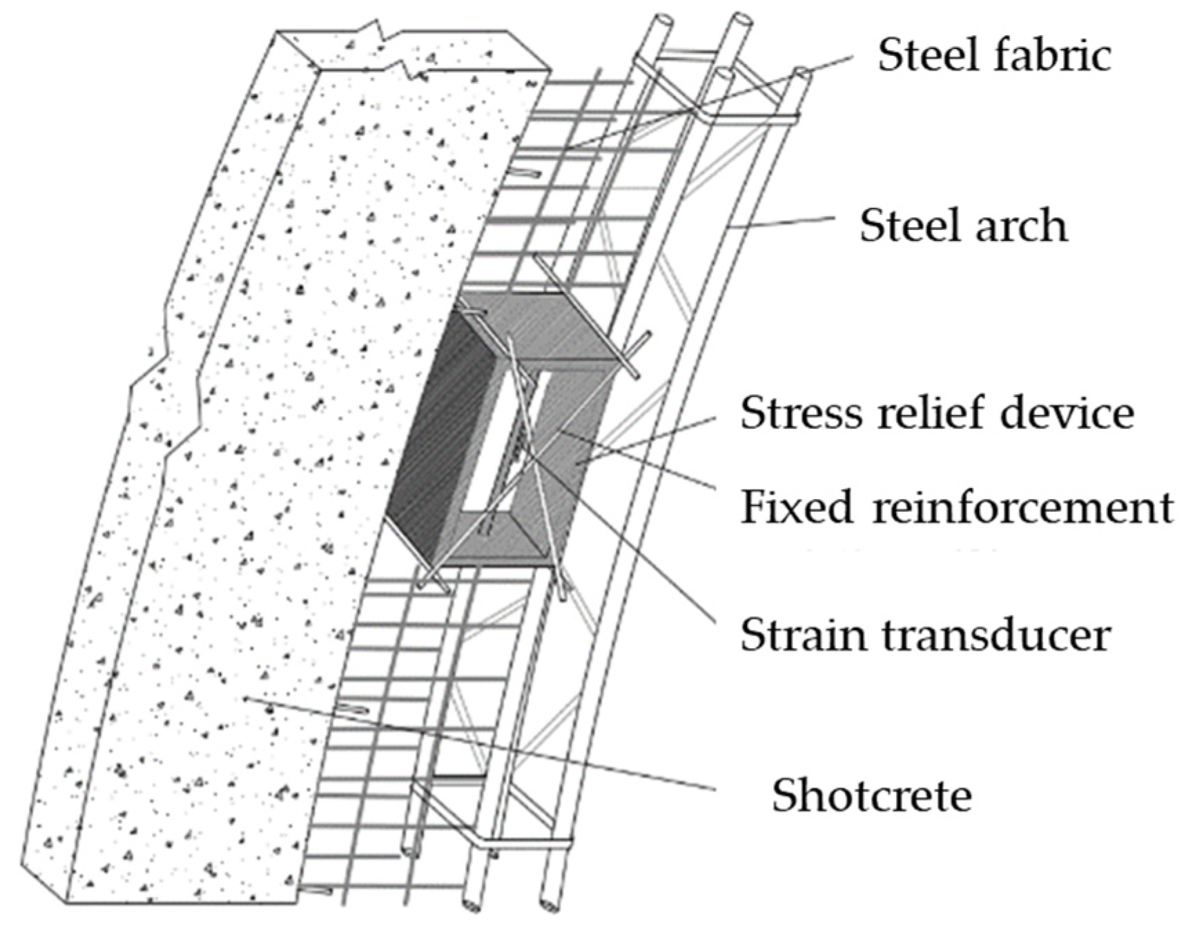
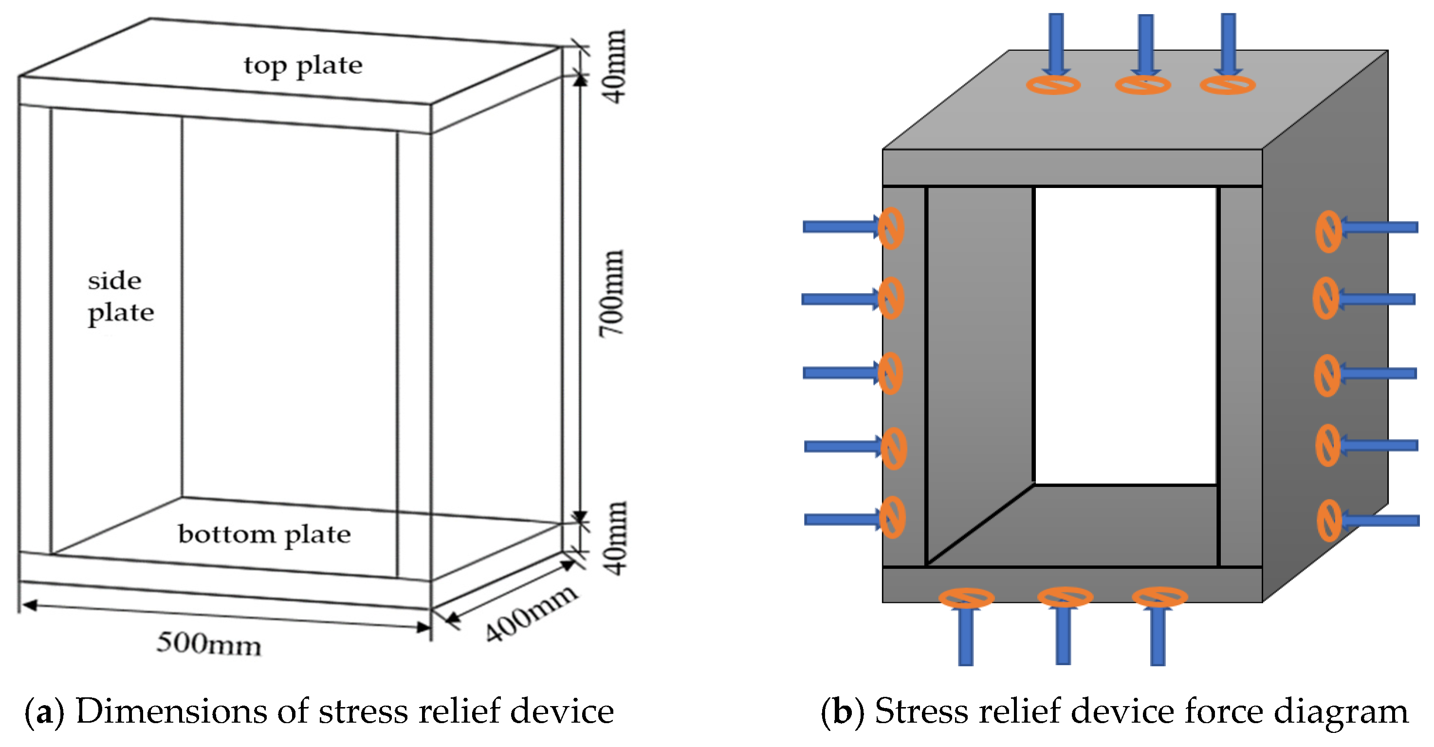
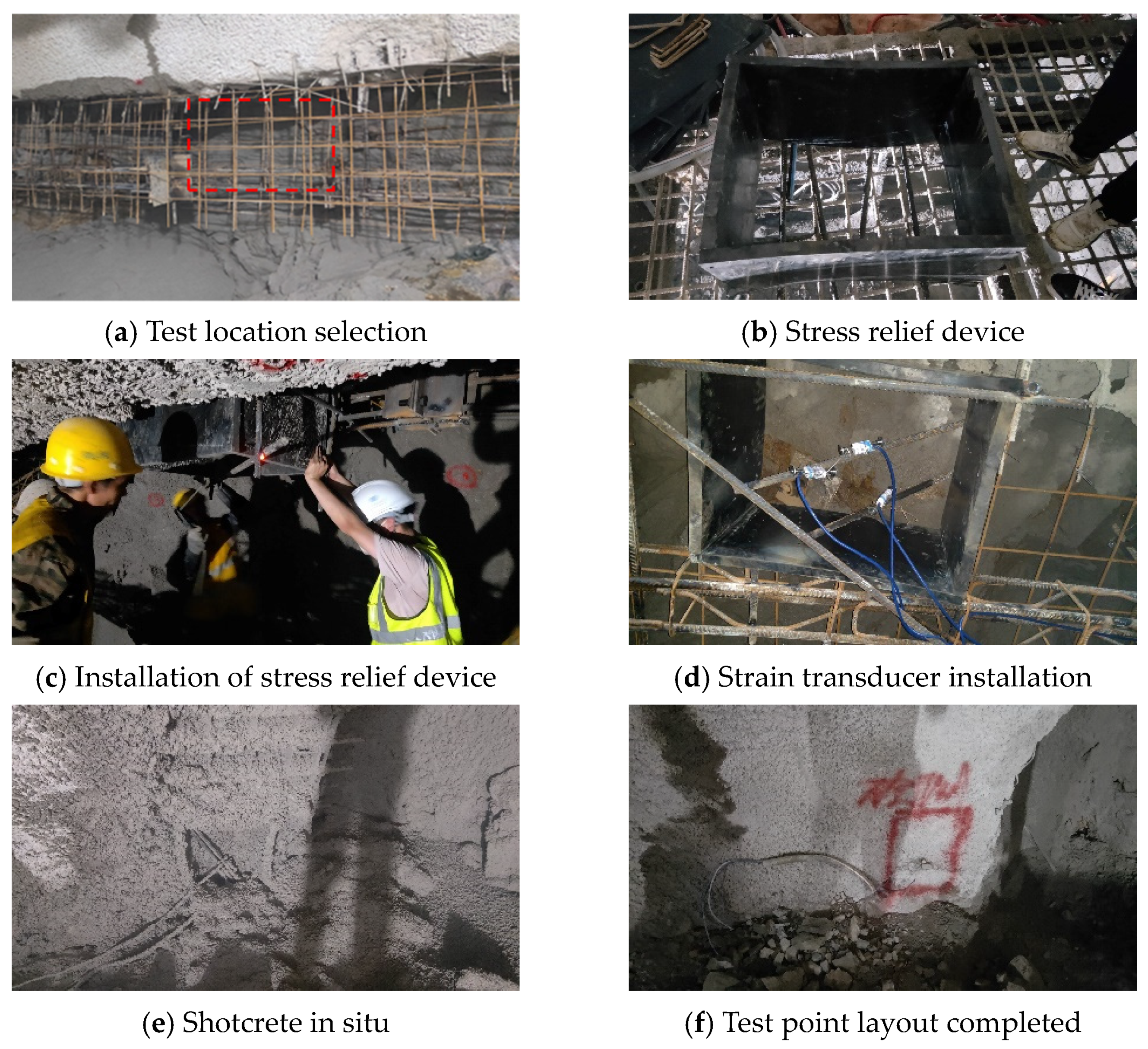
3.2.1. Test Setup
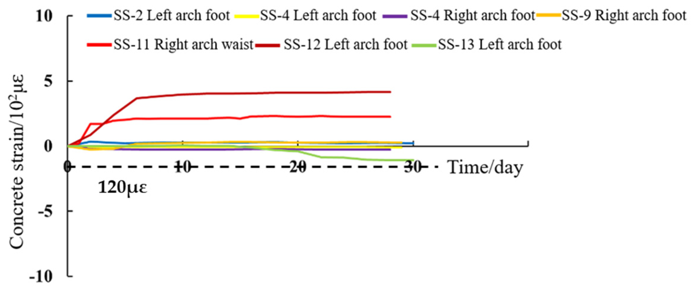
3.2.2. Test Results
- The strain growth stage—Within 3 days after concrete spraying was completed, the internal temperature of the concrete began to drop sharply, resulting in temperature strain developing around the strain gauge. At the same time, the shotcrete began to harden and shrink, causing the strain gauge to record shrinkage strain. In addition, during the spraying of concrete, the spraying pressure generated by the spray gun was high and acted directly on the strain gauge such that it became stressed, thus producing additional strain.
- The strain stabilization stage—On the second to third days after the completion of concrete spraying, the internal temperature of the concrete tended to become consistent with the ambient temperature, and the self-hardening and shrinkage processes effectively ended. The strain rose very slowly under the action of external load and tended to be stable by the seventh day.
3.3. Modification and Safety Assessment of Field Monitoring Results
4. Conclusions
- (1)
- In the process of concrete pouring, the hydration of concrete releases a lot of heat. Concrete expands under heat. Due to the constraining effect of the upper and surrounding rock, the concrete was compressed. At the same time, the arch frame in the initial support restricted the concrete’s expansion. At the initial stage of concrete pouring, the humidity in the near-surface area of the concrete decreased rapidly, forming a large disparity between the moisture level near the surface and that inside the concrete, resulting in tensile strain in the near-surface area. As a result, the strain suffered by the concrete was mainly compressive, with some cases of tensile strain.
- (2)
- In view of the large tensile strain measured in the field test, an indoor direct tensile test was carried out to test the real strain when the primary shotcrete was damaged by tensile failure, and the warning value was adjusted from 90 με to 120 με.
- (3)
- This in situ strain testing of shotcrete excludes the influence of other factors such as arch structure, and the data measured concern the strain suffered by the concrete under the influence of its own hardening and shrinkage, as well as temperature changes and the spraying force. The strain of the concrete reached its peak at 2–3 days, after which there were small fluctuations, and it tended to become stable at around 7 days. The main reason for this is that the early strain of shotcrete is greatly determined by internal temperature changes and hardening and shrinkage, and the shotcrete spraying force greatly impacts the vibrating string strain gauge. Young shotcrete features a large degree of non-loading deformation resulting from shotcrete spraying.
- (4)
- The test results obtained on the third day were finally used as the initial value to calculate the monitoring results for the primary shotcrete, which remedied the inappropriate practice of taking the strain value at the end of the shotcrete spraying process as the initial value. The modified results are in line with the trends derived during real testing in the field, and they can provide guidance and support for tunnel engineering.
Author Contributions
Funding
Data Availability Statement
Conflicts of Interest
References
- Ma, Z.; Sun, J.; Zhang, R.R. Mitigation of Underground Engineering Disaster. Adv. Civ. Eng. 2019, 2019, 7874349. [Google Scholar] [CrossRef]
- Wu, K.; Shao, Z.; Sharifzadeh, M.; Chu, Z.; Qin, S. Analytical Approach to Estimating the Influence of Shotcrete Hardening Property on Tunnel Response. J. Eng. Mech. 2022, 148, 04021127. [Google Scholar] [CrossRef]
- Barla, G.; Bonini, M.; Semeraro, M. Analysis of the behaviour of a yield-control support system in squeezing rock. Tunn. Undergr. Space Technol. 2011, 26, 146–154. [Google Scholar] [CrossRef]
- Hu, B.; Sharifzadeh, M.; Feng, X.-T.; Guo, W.; Talebi, R. Role of stress, slenderness and foliation on large anisotropic deformations at deep underground excavations. Int. J. Min. Sci. Technol. 2021, 31, 577–590. [Google Scholar] [CrossRef]
- Ghorbani, M.; Shahriar, K.; Sharifzadeh, M.; Masoudi, R. A critical review on the developments of rock support systems in high stress ground conditions. Int. J. Min. Sci. Technol. 2020, 30, 555–572. [Google Scholar] [CrossRef]
- Jovičić, V.; Šušteršič, J.; Vukelič, Ž. The Application of Fibre Reinforced Shotcrete as Primary Support for a Tunnel in Flysch. Tunn. Undergr. Space Technol. 2009, 24, 723–730. [Google Scholar] [CrossRef]
- Jeon, S.; You, K.; Park, B.; Park, H.-G. Evaluation of Support Characteristics of Wet-Mixed Shotcrete with Powder Type Cement Mineral Accelerator. Tunn. Undergr. Space Technol. 2006, 21, 425–426. [Google Scholar] [CrossRef]
- Zhao, J.; Meng, X.; Chen, L.; Liu, G.; Zhang, Z.; Xu, Q. Correlation between the mechanical properties and the fiber breaking morphology of fiber reinforced shotcrete (FRS). Compos. Struct. 2021, 277, 114641. [Google Scholar] [CrossRef]
- Afroughsabet, V.; Biolzi, L.; Ozbakkaloglu, T. High-performance fiber-reinforced concrete: A review. J. Mater. Sci. 2016, 51, 6517–6551. [Google Scholar] [CrossRef]
- Wang, J.; Niu, D.; Zhang, Y. Mechanical Properties, Permeability and Durability of Accelerated Shotcrete. Constr. Build. Mater. 2015, 95, 312–328. [Google Scholar] [CrossRef]
- Yuan, Q.; Du, W.B.; Li, Z.K.; Li, S. Research on the Test of the Tensile Strength of Concrete Cylinder by Transverse Cutting Method. Ind. Cons. 2006, 36, 83–87. [Google Scholar]
- Baricevic, A.; Pezer, M.; Rukavina, M.J.; Serdar, M.; Stirmer, N. Effect of polymer fibers recycled from waste tires on properties of wet-sprayed concrete. Constr. Build. Mater. 2018, 176, 135–144. [Google Scholar] [CrossRef]
- Wu, F. Experimental Study on Whole Stress-Strain Curves of Concrete Under Axial Tension; Hunan University: Changsha, China, 2006. [Google Scholar]
- Pal, S.; Shariq, M.; Abbas, H.; Pandit, A.K.; Masood, A. Strength characteristics and microstructure of hooked-end steel fiber reinforced concrete containing fly ash, bottom ash and their combination. Constr. Build. Mater. 2020, 247, 118530. [Google Scholar] [CrossRef]
- Franzén, T. Shotcrete for underground support: A state-of-the-art report with focus on steel-fibre reinforcement. Tunn. Undergr. Sp. Technol. 1992, 7, 383–391. [Google Scholar] [CrossRef]
- Guo, Z.H.; Zhang, X.Q. Experimental Investigation of Complete Stress-Deformation Curves of Concrete in Tension. J. Build. Struct. 1988, 9, 45. [Google Scholar]
- Glišić, B.; Inaudi, D. Monitoring of early and very early age deformation of concrete using fiber optic sensors. In Proceedings of the Second Fib International Congress, Naples, Italy, 5–8 June 2006; Volume 6, pp. 17–26. [Google Scholar]
- Moore, L.; Baweja, D.; Dux, P. Investigation of Early Age Tensile Stresses, Shrinkage strains in pavements and standard drying shrinkage tests. In Proceedings of the 22nd Biennial Conference, Concrete 05—Issues Opportunities Innovations, Melbourne, Australia, 17–19 October 2005; Concrete Institute of Australia: Sydney, Australia, 2005. [Google Scholar]
- Wang, G.J.; Zheng, J.L. In-situ Monitoring and Analysis for Stress-dependent Strains of Early Age Concrete Structures. Eng. Mech. 2009, 26, 61–66. [Google Scholar]
- Altoubat, S.A.; Lange, D.A. Creep shrinkage and cracking of restrained concrete atearly age. ACI Mater. J. 2001, 98, 323–331. [Google Scholar]
- Semianiuk, V.; Tur, V.; Herrador, M.F.; González, M.P. Early age strains and self-stresses ofexpansive concrete members under uniaxial restraint conditions. Constr. Build. Mater. 2017, 131, 39–49. [Google Scholar] [CrossRef]
- Trąmpczyński, W.; Goszczyńska, B.; Bacharz, M. Acoustic Emission for DeterminingEarly Age Concrete Damage as an Important Indicator of Concrete Quality/Condition before Loading. Materials 2020, 13, 3523. [Google Scholar] [CrossRef]
- Debaleena, C.; Chakraborty, D.; Murthy, K.S.R.K. A strain gage technique for thedetermination of mixed mode stress intensity factors of orthotropic materials. Compos. Struct. 2017, 160, 185–194. [Google Scholar]
- Da, B.; Yu, H.; Ma, H.; Tan, Y. Experimental investigation of whole stress-strain curvesof coral concrete. Constr. Build. Mater. 2016, 122, 81–89. [Google Scholar] [CrossRef]
- Fan, Z.; Zheng, C. Rolling predictionmethod of tunnel concrete temperature based on deeplearning. Tunn. Constr. 2023, 43, 611–617. [Google Scholar]
- Do, T.A.; Hoang, T.T.; Bui-Tien, T.; Hoang, H.V.; Do, T.D.; Nguyen, P.A. Evaluation of heatof hydration, temperature evolution and thermal crackingrisk in high-strength concrete at early ages. Case Stud. Therm. Eng. 2020, 21, 100658. [Google Scholar] [CrossRef]
- Witasse, R.; Hendrike, M.A.N. Finite Element Modeling of Early Age Concrete Behavior Using DIANA//Finite Elements in Civil Engineering Applications; CRC Press: London, UK, 2021; pp. 129–134. [Google Scholar]
- Yu, X.Z.; Chen, J.Y.; Xu, Q.; Zhou, Z. Research on the influence factors of thermal cracking in mass concrete by modele xperiments. KSCE J. Civ. Eng. 2018, 22, 2906–2915. [Google Scholar] [CrossRef]
- Van Mier, J.; Van Vliet, M. Uniaxial tension test for the determination of fracture parameters of concrete: State of the art. Eng. Fract. Mech. 2002, 69, 235–247. [Google Scholar] [CrossRef]
- Wee, T.; Lu, H.; Swaddiwudhipong, S. Tensile strain capacity of concrete under various states of stress. Mag. Concr. Res. 2000, 52, 185–193. [Google Scholar] [CrossRef]
- Swaddiwudhipong, S.; Lu, H.; Wee, T. Direct tension test and tensile strain capacity of concrete at early age. Cem. Concr. Res. 2003, 33, 2077–2084. [Google Scholar] [CrossRef]
- Choi, S.; Yang, K.; Sim, J.; Choi, B. Direct tensile strength of lightweight concrete with different specimen depths and aggregate sizes. Constr. Build. Mater. 2014, 63, 132–141. [Google Scholar] [CrossRef]
- Roziere, E.; Cortas, R.; Loukili, A. Tensile Behaviour of Early Age Concrete: New Methods of Investigation. Cem. Concr. Compos. 2015, 55, 153–161. [Google Scholar] [CrossRef]
- Chen, C.S.; Yan, D.H.; Chen, Z.Q.; Tu, G.Y.; Tian, Z.C. Technique Research of Vibrational Chord Strain Gauge to Concrete. China J. Hwy. Trans. 2004, 01, 33–37. [Google Scholar]


| Monitoring Items | Physical Quantity | Instrument Name | Specification |
|---|---|---|---|
| Bolt axial force | Bolt axial force gauge | MSJ | |
| Concrete strain | Concrete strain gauge | EM-30 | |
| Steel rib stress | Rebar stress gauge | STG-25 |
| Item | Specification | Loading Rate | Quantity |
|---|---|---|---|
| Shotcrete | C30 | 0.002 mm/min | 2 |
| Strain gauge | 120-88AA | - | 3 |
| Position | Number of Measuring Points | Number of Tensile Measuring Points | Proportion of Tensile Measuring Points |
|---|---|---|---|
| Arch foot | 124 | 34 | 27.42% |
| Arch waist | 71 | 13 | 18.31% |
| Arch top | 31 | 6 | 19.35% |
Disclaimer/Publisher’s Note: The statements, opinions and data contained in all publications are solely those of the individual author(s) and contributor(s) and not of MDPI and/or the editor(s). MDPI and/or the editor(s) disclaim responsibility for any injury to people or property resulting from any ideas, methods, instructions or products referred to in the content. |
© 2024 by the authors. Licensee MDPI, Basel, Switzerland. This article is an open access article distributed under the terms and conditions of the Creative Commons Attribution (CC BY) license (https://creativecommons.org/licenses/by/4.0/).
Share and Cite
Sun, S.; Tian, H.; Zhang, Z.; Diao, Z.; Deng, L.; Yang, X.; Li, C. Tensile Deformability of Shotcrete in Tunnel Primary Support: A Case Study. Buildings 2024, 14, 2993. https://doi.org/10.3390/buildings14092993
Sun S, Tian H, Zhang Z, Diao Z, Deng L, Yang X, Li C. Tensile Deformability of Shotcrete in Tunnel Primary Support: A Case Study. Buildings. 2024; 14(9):2993. https://doi.org/10.3390/buildings14092993
Chicago/Turabian StyleSun, Shunxian, Haiguang Tian, Zhanjun Zhang, Zhaoke Diao, Longhua Deng, Xuxu Yang, and Chunmeng Li. 2024. "Tensile Deformability of Shotcrete in Tunnel Primary Support: A Case Study" Buildings 14, no. 9: 2993. https://doi.org/10.3390/buildings14092993
APA StyleSun, S., Tian, H., Zhang, Z., Diao, Z., Deng, L., Yang, X., & Li, C. (2024). Tensile Deformability of Shotcrete in Tunnel Primary Support: A Case Study. Buildings, 14(9), 2993. https://doi.org/10.3390/buildings14092993