Article

Experimental Study on Flexural Behavior of Retard-Bonded Prestressed UHPC Beams with Different Reinforcement Ratios

1
College of Civil Engineering, Henan University of Technology, Zhengzhou 450001, China
2
China Construction Seventh Engineering Division Corp. Ltd., Zhengzhou 450004, China
*
Author to whom correspondence should be addressed.
Buildings 2025, 15(6), 887; https://doi.org/10.3390/buildings15060887
Submission received: 2 February 2025 / Revised: 5 March 2025 / Accepted: 10 March 2025 / Published: 12 March 2025

Abstract

:
Ultra-high performance concrete (UHPC), functioning as a next-generation cementitious engineering material, demonstrates marked superiority over conventional concrete in critical performance metrics, with its groundbreaking characteristics primarily manifested through exceptional strength and enhanced durability parameters. To address structural demands for reduced self-weight, material efficiency, and simplified construction processes in large-span durable structures, this study proposes a retard-bonded prestressed UHPC (RBPU) beam combining UHPC with retard-bonded prestressing tendons (RBPTs). Three RBPU beam specimens, with varying reinforcement ratios, underwent flexural testing to quantitatively assess their bending performance characteristics, providing foundational references for design optimization. The test results show that the failure mode of RBPU beams is typical flexural failure, demonstrating good load-bearing capacity and excellent ductility. As the reinforcement ratio increases, the cracking moment (Mcr) is improved to some extent, while the ultimate moment (Mu) and ductility are significantly enhanced. The plastic influence coefficient of the section modulus (γ) in the calculation of the Mcr was revised, and the ultimate moment Mu was subsequently calculated. The comparison demonstrates good agreement between the experimental values and computational results. This study provides both experimental and theoretical references for further in-depth research and practical applications of RBPU beams.

1. Introduction

Ultra-high performance concrete (UHPC), an advanced cementitious composite material, is characterized by a dense cementitious matrix uniformly reinforced with steel fibers [1]. It exhibits exceptional mechanical properties, including a superior compressive strength, elevated elastic modulus, high tensile performance, and enhanced durability [2,3,4]. The implementation of UHPC enables a significant reduction in structural member cross-sections while simultaneously decreasing the overall structural self-weight. These superior material properties have garnered substantial attention within the architectural and structural engineering communities [5,6,7].
The retard-bonded prestressing system is a specialized structural technique characterized by a sheathing with transverse ribs analogous to corrugated ducts, wherein the annular space between the prestressing strand and sheathing is densely filled with a newly developed retarded adhesive material [8]. The retarder-bond adhesive cures at ambient temperature, eliminating the need for on-site heating equipment and preventing thermal impacts on formwork and concrete, while significantly reducing energy consumption and associated costs. The structural configuration of an RBPT is delineated in the schematic diagram provided in Figure 1. During the construction phase, the retarded adhesive remains in an uncured state, resulting in an unbonded interaction between the strand and retarded-bond material within retard-bonded prestressing tendons (RBPTs). This configuration permits unconstrained strand movement within the sheathing. Distinct from unbonded prestressing systems that require dedicated duct reservation, this technology minimizes cross-sectional weakening, thereby enhancing the structural load-bearing capacity to a certain extent. Furthermore, it eliminates the grouting process essential in bonded prestressing systems, effectively mitigating potential quality defects associated with grouting operations. Upon the commencement of service post-construction, the complete polymerization of the retarding adhesive enables RBPTs to achieve mechanical performance parameters equivalent to those of conventional bonded prestressing tendons [9]. This innovative technology amalgamates the inherent construction expediency of unbonded prestressed systems with the superior structural characteristics of bonded prestressed concrete. It optimizes the construction process when employing prestressing techniques and is particularly suitable for high-performance buildings and structures that demand enhanced performance specifications [10,11].
The integration of ultra-high performance concrete (UHPC) with prestressing technology has been a significant advancement in structural engineering, driven by UHPC’s exceptional compressive strength and superior crack control capabilities [12,13,14]. Bahmani et al. [15] demonstrated that UHPC with 50% steel slag replacement of silica sand achieves significant improvements in compressive, flexural, and tensile strengths (by 13.5%, 20.8%, and 6.5%, respectively), while achieving a 5.1% reduction in carbon emissions, thereby validating steel slag’s potential as a sustainable aggregate in engineering applications. Tian et al. [16] established a computational framework employing 3D nonlinear FE modeling to replicate the bending responses of post-tensioned UHPC members, deriving an analytical protocol for failure mode identification. El-Helou et al. [17] conducted displacement-controlled destructive tests on prestressed UHPC bridge beams to assess their flexural behavior, subsequently developing a design methodology rooted in equilibrium and strain compatibility principles for such structural components. Through the full-scale failure testing of web-reinforcement-free prestressed UHPC-RC composite beams, Sun et al. [18] systematically outlined the critical reinforcement ratio for hybrid-reinforced members, developing a computational model for determining the minimum reinforcement ratio that incorporates UHPC’s tensile contribution. Sim et al. [19], based on experimental validation and numerical examples, recommended prioritizing UHPC’s tensile performance over its ultra-high compressive strength in flexural design, achieving optimal performance and economic efficiency while reducing the need for shear reinforcement. Li et al. [20] conducted experimental investigations on large-scale prestressed UHPC beams through bending tests, proposing a modified UHPC tensile constitutive model that incorporates UHPC’s tensile strength contribution for the accurate prediction of flexural performance. Leutbecher et al. and Yang et al. [21,22] considered fiber-bearing effects in the flexural cracking of prestressed UHPC beams, developing design methods that effectively reflect experimental bending capacities. Deng et al. [23] experimentally investigated the flexural behavior of prestressed UHPC beams reinforced with hybrid fibers, calculating cracking and ultimate moments based on the plane-section assumption while considering short fiber bridging effects, with good agreement between the experimental and calculated values. Through the computational modeling of unbonded prestressed UHPC beams, Dogu et al. [24] developed a theoretical framework capable of simulating full-range moment–curvature relationships. Their sensitivity analysis revealed that structural ductility exhibited strong dependency on two key variables: the maximum attainable tensile strain in the UHPC and specific load application patterns. Zhang et al. [25,26] developed a UHPC reinforcement system using pre-tensioned layers, with four-point bending tests investigating flexural performance. Their numerical framework accurately predicts cracking and the ultimate load in strengthened beams. Li et al. [27] investigated the performance of UHPC-NC composite beams through experimental analysis, focusing on three critical parameters: UHPC thickness, prestressing level, and normal concrete compressive strength. Their finite strip model demonstrated reliable accuracy in predicting flexural responses. Mohebbi et al. [28] developed data-driven models for predicting creep and shrinkage behavior in UHPC-like materials, enabling the accurate estimation of prestress losses in UHPC beams. Joh et al. [29] measured the prestress transfer length, development length, and prestress losses in UHPC-cast beams, demonstrating that creep and shrinkage contributed minimally to prestress losses. These studies collectively advance the understanding and application of prestressed UHPC in structural engineering, providing robust methodologies for design and analysis. Zheng et al. [30] demonstrated that the combination of external prestressing and UHPC materials can significantly enhance crack resistance in negative moment regions (with cracking load increased by 118.8% to 148%), and established an ultimate bearing capacity calculation formula that provides a theoretical basis for the engineered design. Feng et al. [31] systematically evaluated the reliability of predictive models as regards flexural capacity in both ordinary reinforced UHPC beams and prestressed UHPC beams across various design codes, while calibrating material partial safety factors and structural safety factors through comprehensive analyses.
The novel structural system combining retard-bonded prestressing tendons (RBPTs) and UHPC can fully exploit the properties of these two high-strength materials; significantly reduce structural self-weight; save construction materials; and greatly enhance the performance of structures with long spans, heavy loads, or high importance. Current research on retard-bonded prestressed structures primarily focuses on their combination with normal concrete. Cao et al. [32,33] compared the mechanical properties of retard-bonded prestressed concrete (RBPC) beams with those of traditional bonded prestressed concrete (BPC) beams. They found that the mechanical properties of the two are similar, with RBPC beams even slightly outperforming BPC beams. Wang et al. [34] selected a retard-bonded prestressed concrete beam at a construction site as a test subject for monitoring, revealing the stress transfer mechanism in the concrete of the test beam. They analyzed the critical sections of the test beam using an ANSYS model to provide early warnings. However, research on the combination of RBPTs and UHPC remains limited. Xiong et al. [35] conducted experimental research on a large-scale variable-section π-shaped beam using RBPTs and UHPC. The results showed that the beam exhibited excellent load-bearing capacity and ductility.
Currently, research on the flexural behavior of retard-bonded prestressed UHPC (RBPU) beams remains scarce, which hinders the accurate elucidation of the bending mechanism of this novel system. To investigate the flexural performance of RBPU beams and study the influence of different reinforcement ratios on their flexural behavior, thereby revealing the flexural mechanism of this novel system, this research designed three RBPU beams with varying reinforcement ratios and conducted four-point bending tests. During the loading process, parameters such as load, strain, and crack development were monitored. Based on the material properties of both UHPC and RBPTs, we calculated the cracking moment and ultimate moment of RBPU beams. The results of this study validate the flexural performance of beams combining RBPTs and UHPC, providing valuable insights and theoretical support for the design and analysis of RBPU beams.

2. Experimental Program
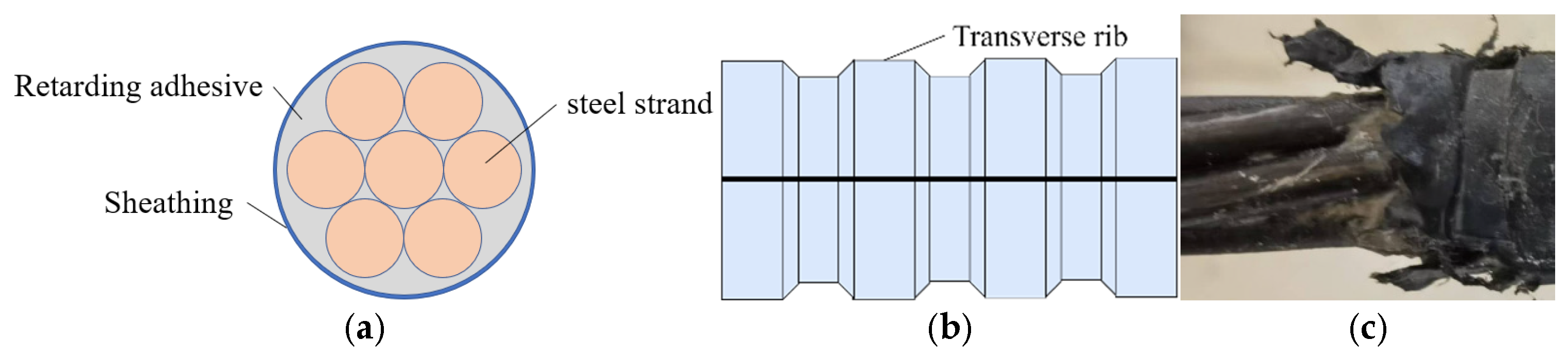
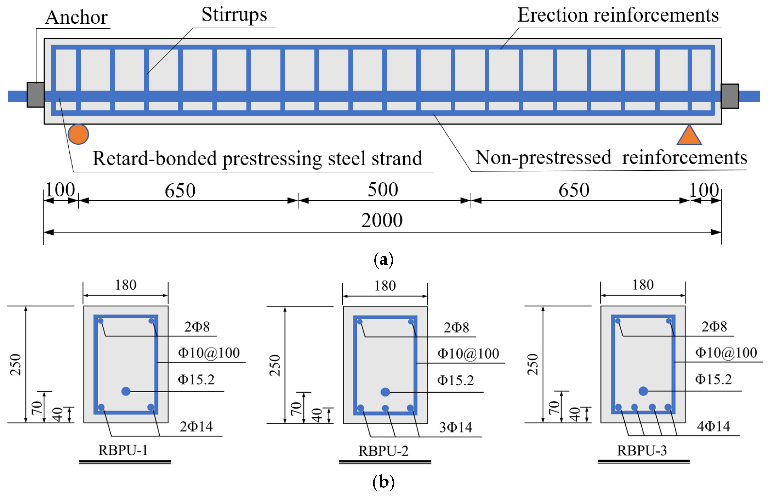
2.1. Test Specimens

Three RBPU beam specimens were fabricated for flexural tests, with their structural configurations and parameters visually presented in Figure 2 and tabulated in Table 1, respectively. The beam span was 2000 mm, the effective length was 1800 mm, and the cross-sectional dimensions were 180 mm × 250 mm. All the beam specimens were made with retard-bonded prestressing steel strands of a 15.2 mm diameter and featuring a transverse rib thickness of 1.2 mm, transverse rib width of 9 mm, transverse rib height ≥ 1.2 mm, and transverse rib spacing of 13 mm, incorporating two 8 mm diameter erection reinforcements on the compression side and 10 mm diameter stirrups arranged at 100 mm intervals along the beam length. At the positions where tension force was applied at both ends of the beam, steel plates with dimensions of 180 mm × 140 mm and a thickness of 20 mm were embedded. After tensioning, low-shrinkage anchorage was used for anchoring.
Figure 3 illustrates the fabrication process of the RBPU beam. In the first step, the reinforcement cage was tied. Upon the completion of the rebar tying process, the assembled reinforcement cage and end-plate system were positioned within the timber formwork, and the retard-bonded prestressing steel strands were fixed at the designated positions. Finally, the different components of UHPC were poured into the concrete mixer according to the mix design, and after mixing for the appropriate duration, the UHPC was poured into the mold for casting. After casting was finished, a plastic film was used to cover the surface of the beam specimen. The specimens then underwent curing under laboratory conditions (the ambient temperature was maintained at 25–30 °C) throughout the 28-day hardening period. Subsequently, within the tensioning application period, an electric oil pump was used to tension and anchor the prestressed steel strands. After the retarding adhesive had fully cured, the bending test was conducted on the specimen.

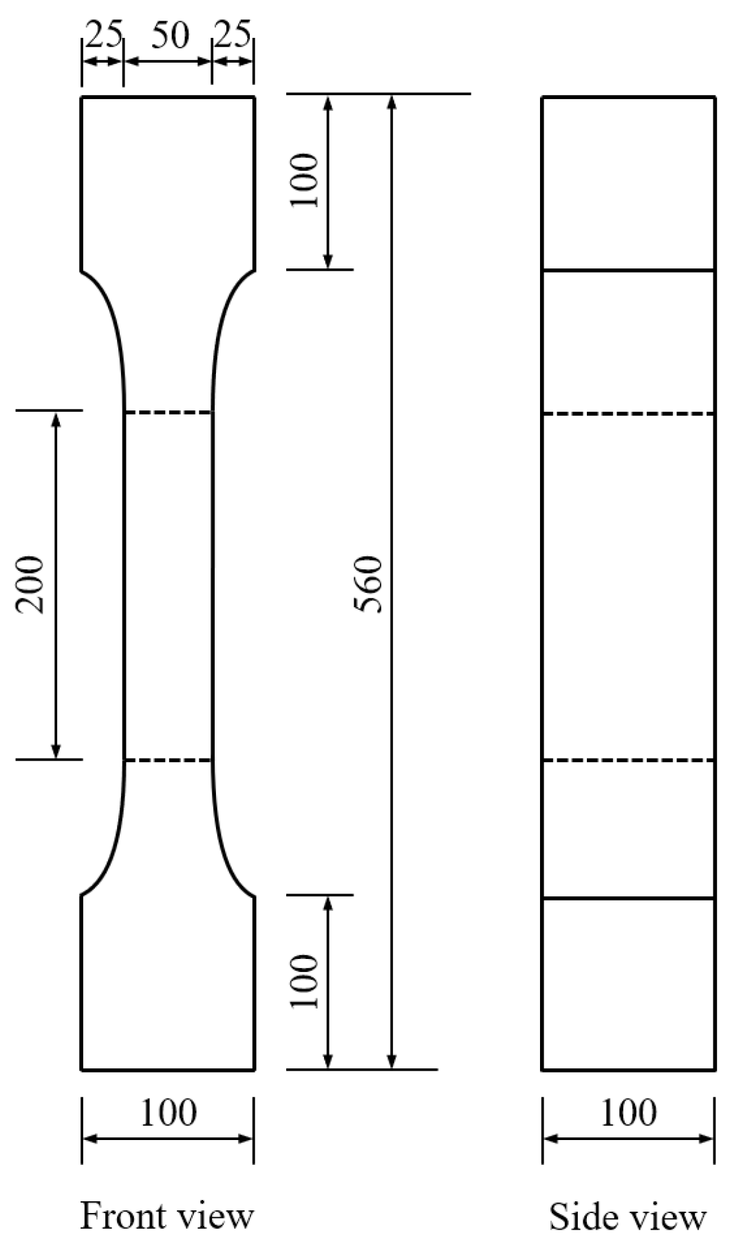
2.2. Material Properties

This investigation employed brass-coated steel fibers at a 2% volumetric integration within the UHPC matrix, comprising equal proportions (50% each) of straight and hooked-end fibers measuring 13 mm and 14 mm in length, respectively, both maintaining a 0.2 mm diameter. The constituent materials, including specialized pre-blended UHPC powder and steel fibers, were sourced from Zhejiang Hongri Tenacal New Material Technology Co., Ltd. (Zhejiang, China), with the manufacturer’s proprietary formulation details tabulated in Table 2 [1]. The steel fibers demonstrated a characteristic tensile strength of 2000 MPa, with a corresponding elastic modulus reaching 200 GPa. Consistent with RBPU beam curing protocols, triplicate sets of 100 mm3 cubic molds and standardized dog-bone specimens were cast from identical UHPC batches. Mechanical evaluation was conducted in compliance with T/CECS864-2021 [36], with the dog-bone specimen geometry specifications illustrated in Figure 4. Post 28-day curing, the material demonstrated a characteristic compressive strength of 121.6 MPa and tensile capacity of 6.9 MPa. The mean values from the mechanical characterization tests are systematically compiled in Table 3.
The grades of the reinforcement and steel strand are HRB400 and 1860, respectively. Uniaxial tensile testing protocols were implemented in strict accordance with GB/T 228.1-2021 [37] (reinforcement) and GB/T 21839-2019 [38] (steel strand) to characterize their mechanical performance. Table 4 presents the experimentally determined mechanical characteristics of reinforcement and prestressing strands of various diameters.

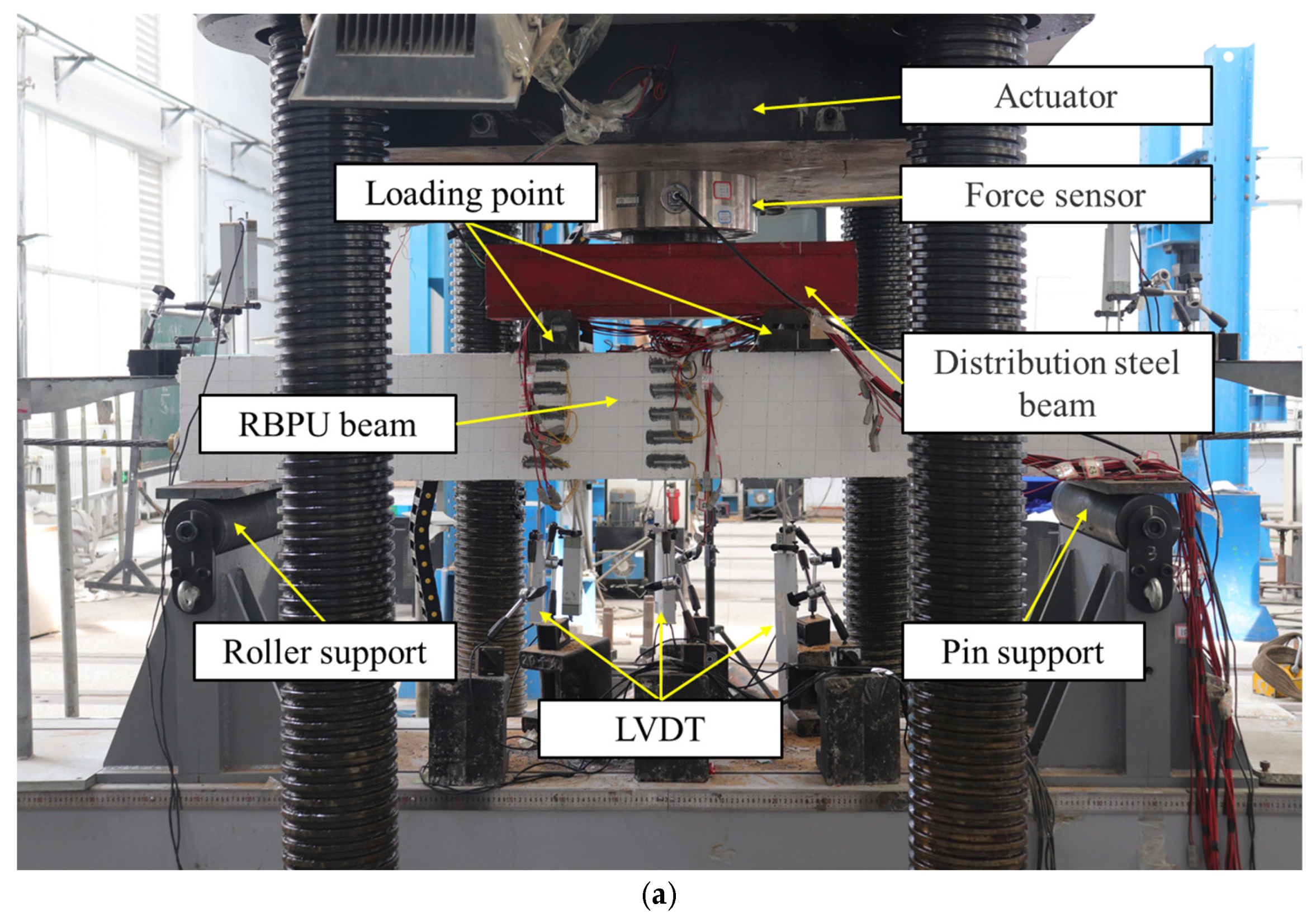
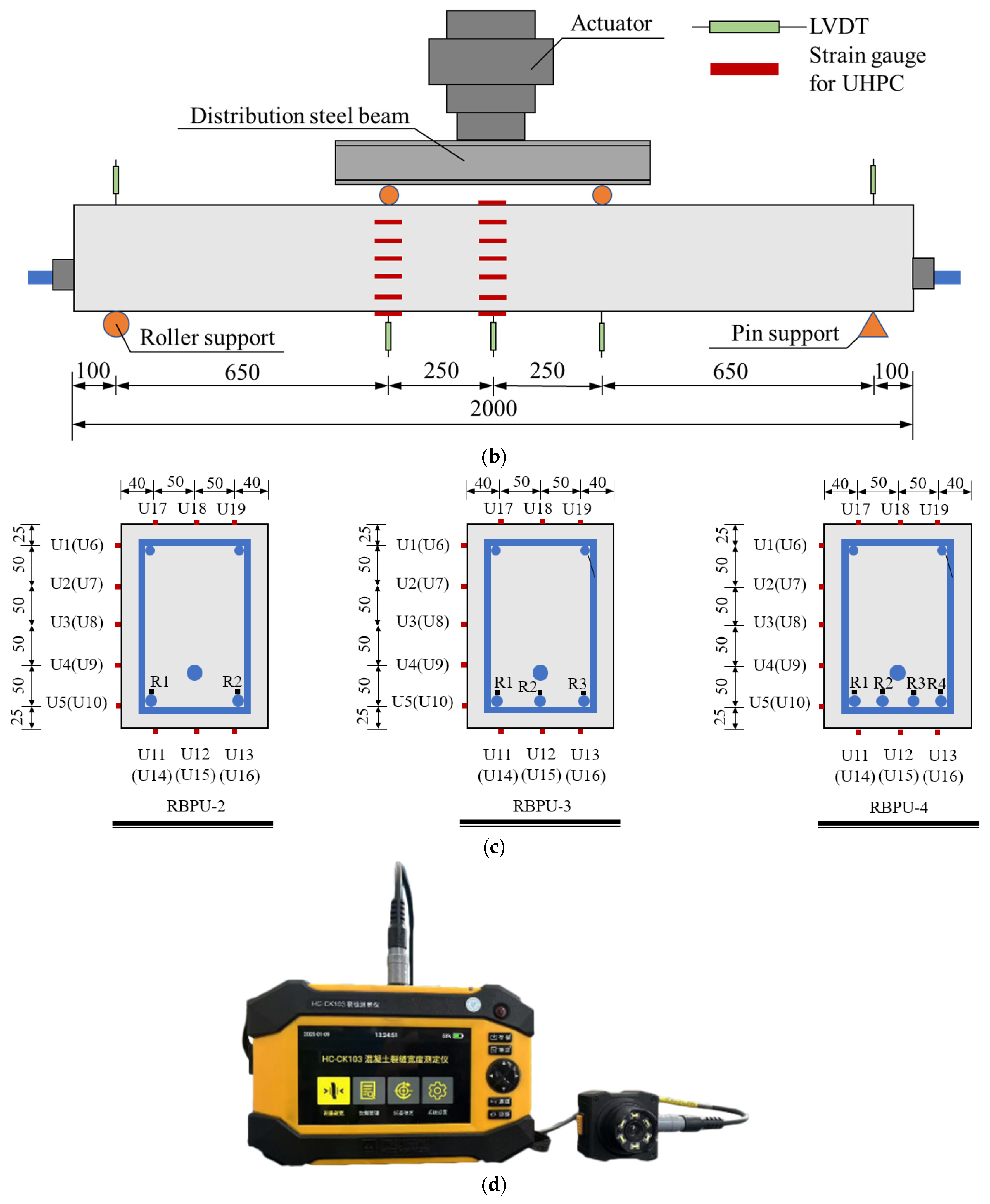
2.3. Test Setup and Instrumentation

The experimental configuration and measurement devices are illustrated in Figure 5. The test beams rested on simple supports and were subjected to four-point bending evaluation using a 12,000 kN electro-hydraulic servo system. As demonstrated in Figure 5b, the specimens featured a 500 mm pure bending segment and 650 mm shear zone, achieving a shear span–depth ratio of 3.1. Initial calculations were performed to determine the theoretical cracking and failure loads before formal testing commenced. Following the code of GB/T50152-2012 [39], preliminary loading at 5% of the predicted failure load preceded formal testing to verify the equipment’s functionality and eliminate system clearance. The bending protocol implemented phased loading strategies: a pre-yield phase that utilized force-controlled increments (20 kN/step) at 6 kN/min, with stabilization periods for crack documentation using the HC-CK103 crack-monitoring device (Beijing Haichuang High Technology Co., Ltd. (Beijing, China), ±0.01 mm precision), and a post-yield transition to displacement-controlled loading at 0.6 mm/min with 2 mm displacement increments per phase.
The instrumentation layout is detailed in Figure 5b. Ten linear variable differential transformers (LVDTs) were positioned at the beam’s mid-span, loading points, and support regions to record the vertical displacement responses under load. Strain measurements were obtained through gauges mounted on the UHPC surface (top, bottom, and lateral faces) and targeted longitudinal reinforcement. Figure 5c shows the strain gauge distribution: labels U1–U19 correspond to UHPC measurement points, while R1–R4 identify reinforcement strain-monitoring locations.

3. Experimental Results and Discussion

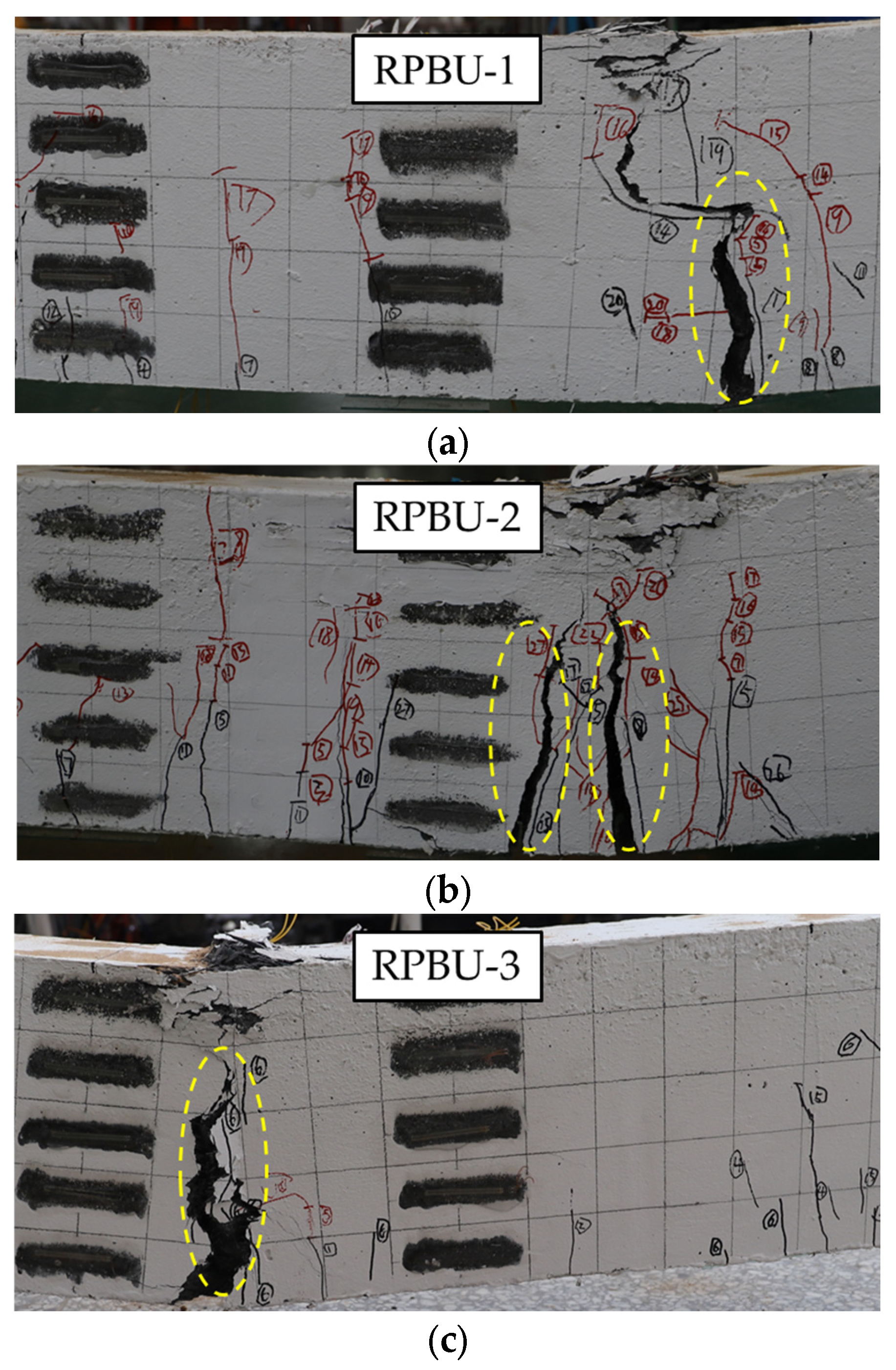
3.1. Failure Modes and Crack Patterns

The failure characteristics and fracture distributions are presented in Figure 6. All three specimens exhibited flexural-dominated failure patterns consistent with conventional bending failure mechanisms, featuring compressive failure in the upper UHPC zone coupled with the simultaneous yielding of non-prestressed reinforcements and prestressed reinforcements.
During the initial loading phase, the specimens remained uncracked under small bending moments, demonstrating linear elastic behavior with a stable neutral axis position. During the post-cracking to pre-yielding phase, progressive loading triggered crack initiation across the pure bending segment, accompanied by upward neutral axis migration. Three key crack parameters—number, width, and propagation length—progressively increased with the applied load. The transition to the yielding phase manifested through dominant macrocracks (typically 1–2 primary fractures) within the bending region, exhibiting accelerated width expansion and vertical penetration toward the compressive failure zone. The synergistic interaction between steel fiber bridging mechanisms and prestressing technology in RBPU beams significantly retards macrocrack propagation while enhancing crack distribution homogeneity compared to conventional reinforced concrete systems [23]. Following peak load attainment, crack stabilization occurred as fracture propagation ceased. The post-peak degradation phase manifested through fiber extraction in tensile regions concurrent with compressive zone deterioration involving UHPC fragmentation, ultimately culminating in structural failure. At this point, the compression zone of the RBPU beam only experienced slight UHPC spalling and did not exhibit significant spalling or bulging as seen in ordinary reinforced concrete. The ultra-high strength of UHPC, combined with the bridging effect of steel fibers, enables it to withstand higher loads and reduces its susceptibility to cracking, resulting in a unique behavioral pattern that differs from ordinary reinforced concrete systems.

3.2. Load–Deflection Relationship

The mid-span load–deflection response, as presented in Figure 7, reveals three distinct phases: (1) a linear-elastic regime preceding the tensile cracking of UHPC; (2) a nonlinear hardening phase post-cracking with nonlinear stiffness evolution, and (3) a post-yielding degradation phase marked until specimen beam failure.
In the linear-elastic regime preceding tensile UHPC cracking, the bending moments remain below critical thresholds, with the stress levels in both the tensile reinforcement and UHPC maintained within elastic limits. The beam’s stress condition resembles that of a homogeneous elastic beam, with the load–displacement curve ascending almost linearly. Following the initiation of UHPC cracking, the load–displacement response transitions to a nonlinear hardening phase. The slope of the curve does not decrease significantly, and the inflection point is not pronounced, with the load–displacement curve of the specimen still approximating a linear progression. This behavior likely stems from the crack-inhibiting mechanism of the retard-bonded prestressing steel strands, resulting in an insignificant reduction in the beam’s stiffness, thereby minimizing the impact of UHPC cracking on the overall stiffness of the test beam. As the curve ascends, a gradual divergence in the curves can be observed, with specimens exhibiting higher reinforcement ratios demonstrating greater stiffness during this phase. Furthermore, there is a strong positive correlation between the reinforcement ratio and flexural capacity enhancement in RBPU beams, demonstrating parametric sensitivity of the reinforcement ratio to the bending resistance characteristics.
When the load–deflection curve reaches a certain level, the curve noticeably decelerates, and the specimen’s stiffness decreases significantly, signifying the specimen’s entry into the yielding phase. This stage exhibits rapid strain escalation in non-prestressed reinforcement, coordinated with progressive growth in mid-span deflection and neutral axis elevation. A slight decline in the curve of specimen RBPU-3 is observed before it continues to rise slowly, a phenomenon attributed to the internal force redistribution within the specimen.
With continued loading, the load increases gradually. The load attains its maximum prior to UHPC spalling initiation within the beam’s pure bending segment, followed by a progressive decline in load-bearing capacity. At a mid-span deflection of 47.73 mm, the non-prestressed reinforcement in specimen RBPU-1 fractures. At this juncture, the mid-span displacement has exceeded the 1/50L0 stipulated by the code of GB/T 50152-2012 [39], and while the load decrease is not pronounced in any of the test beams, the other two specimens can still sustain further loading. This indicates that RBPU beams configured in this manner possess commendable deformation capacity and ductility.

3.3. Flexural Capacity and Ductility

The experimental testing results are detailed in Table 5, including the characteristic load and corresponding mid-span deflection. Structural ductility in concrete systems refers to a sustained deformation capability post-yielding while load resistance is maintained, indicative of energy absorption potential. This property is quantified through the displacement ductility coefficient (μ), expressed as follows:
μ = δ u δ y
where δu represents the failure load-induced deflection. Most of the RBPU beams did not exhibit significant load reduction. For the analysis of the RBPU beams, the failure load was defined at 95% peak load magnitude [40], enabling parametric influence quantification. δy denotes the deflection corresponding to the yield load, which was calculated using the farthest point method as described in ref. [41]. The calculated displacement ductility factors for all the tested beams are presented in Table 5.
Figure 8 demonstrates how varying the reinforcement ratios affected bending performance. According to the experimental results recorded in Table 5 and visualized in Figure 8, progressive increases in the total reinforcement ratio from 1.28% to 2.10% elevated the cracking load by 11.22%, yield load by 48.11%, and maximum load capacity by 53.04%. The limited impact of reinforcement ratio elevation on cracking load originates from its inability to augment UHPC’s inherent tensile properties. Elevated reinforcement ratios substantially strengthen the total tensile resistance within the beam’s tension regions, which drives significant improvements in both yield load thresholds and maximum load capacities. This mechanical enhancement directly contributes to superior flexural performance in RBPU beam systems.
Furthermore, the experimental data in Table 5 and Figure 8 reveal displacement ductility factors exceeding 6.0 across all the specimens, demonstrating superior deformation performance. When the total ratio of reinforcement increases from 1.28% to 2.10%, the displacement ductility factors of the specimens increase by 39.34%. This suggests that, within this configuration, a higher ratio of reinforcement results in greater deformation capacity of the specimens. This conclusion is similar to that of Shao et al. [42], indicating that increasing the reinforcement ratio within the range of 0.96% to 2.1% can significantly enhance ductility.

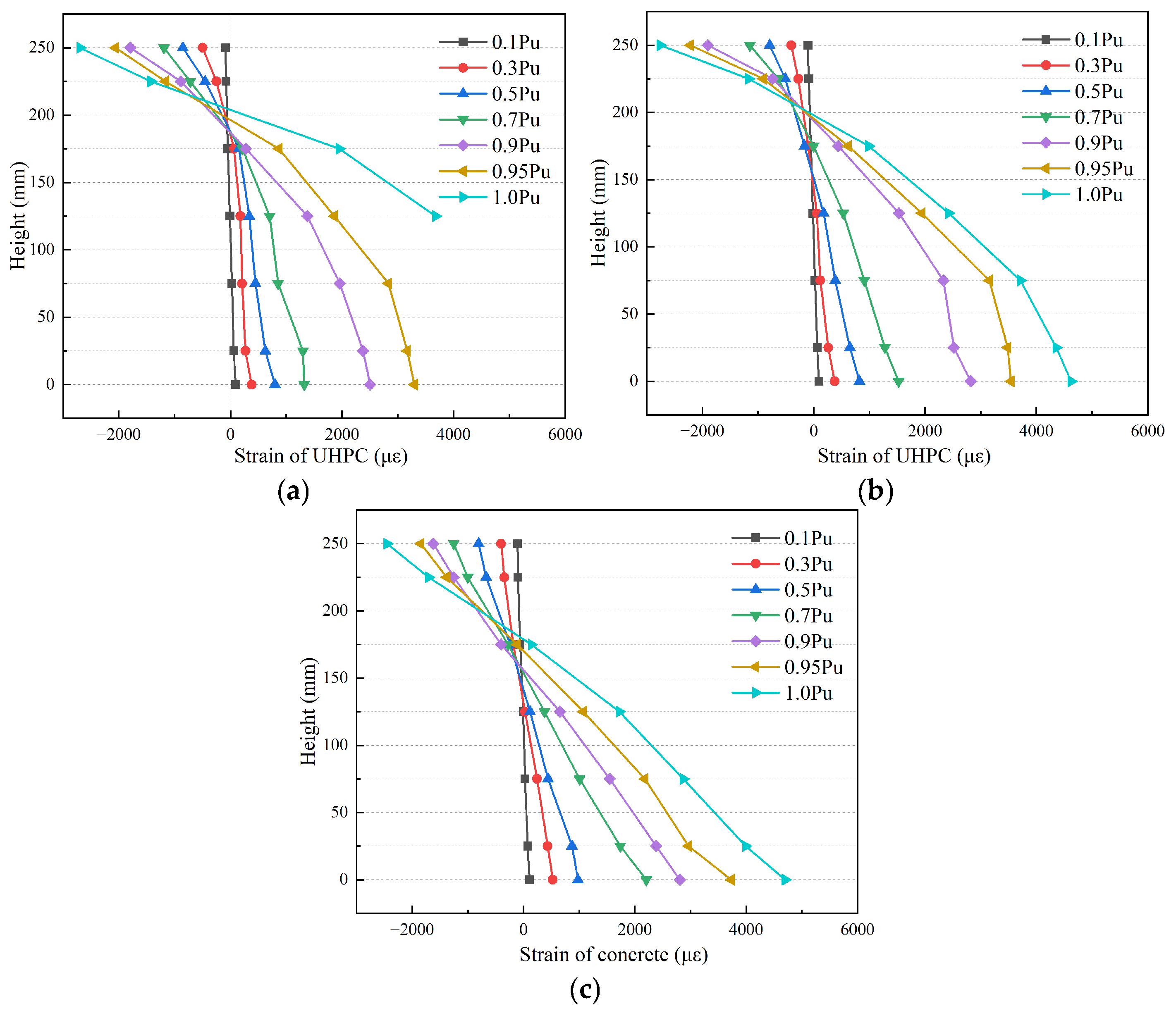
3.4. UHPC Strain of Mid-Span Section

Strain gauge placement (Figure 5) enabled the measurement of the UHPC’s strain distribution under loading (Figure 9). The linear strain profile across the mid-span sections validates the plane-section hypothesis, demonstrating consistent compliance with fundamental beam theory. The analysis indicates that the neutral axis remained stable until the tensile-zone concrete cracked. Once the load surpassed the cracking point, the neutral axis began to move upward, accelerating significantly after the specimen yielded.

4. Theoretical Analysis of Flexural Capacity

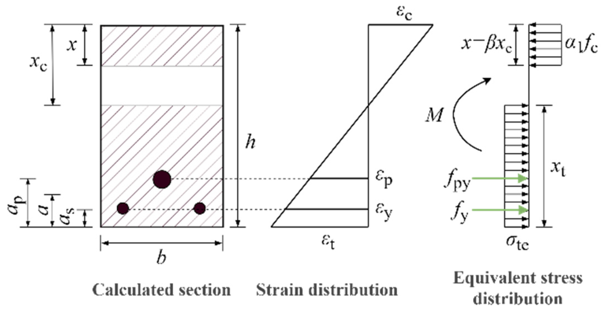
4.1. Basic Assumptions

Firstly, it is postulated that the RBPU beam adheres to the plane-section hypothesis. The cross-sections perpendicular to the beam axis (i.e., the cross-sections of the member) subjected to pure bending remain planar after deformation and orthogonal to the deformed member axis. Each cross-section undergoes rotation, and the rotation of each cross-section can be determined by two rotational angles. Secondly, the slip between the tensile reinforcement, the slowly bonded prestressing steel strands, and the UHPC is neglected.

4.2. Calculation of Prestressing Losses

The retard-bonded prestressed UHPC beam specimen can be regarded as a post-tensioned construction element, and its prestress loss can be calculated in two stages. In the first stage, the prestress loss includes the following: the loss due to the deformation of the anchorage at the tensioning end and retraction of the retard-bonded prestressing steel strand ( σ l 1 ), as well as the loss caused by friction between the prestressing steel strand and the sheathing wall ( σ l 2 ). In the second stage, the prestress loss consists of the stress relaxation of the prestressing steel strand ( σ l 4 ) and the shrinkage and creep of UHPC ( σ l 5 ). The calculation methods for each type of prestress loss are based on the definitions provided in the code of JGJ387-2017 [43], as shown in Equations (2)–(5), and the calculation results are presented in Table 6.
σ l 1 = a l E p
σ l 2 = σ con κ x + μ θ
σ l 4 = 0.125 σ con f ptk 0.5 σ con
σ l 5 = 55 + 300 σ pc f cu 1 + 15 ρ
where a represents the deformation of the anchorage and the retraction value of the prestressing tendon, which can be taken as 5 mm; l denotes the distance between the tensioning end and the anchoring end; E p is the elastic modulus of the prestressing tendon; κ is the friction coefficient accounting for the local deviation per meter length of the sheath wall of the retard-bonded prestressing steel strand, which can be taken as 0.006; x is the length from the tensioning end to the calculated section; θ is the radian value corresponding to the angle between the tangent of the curve and the line from the tensioning end to the calculated section; σ pc represents the normal compressive stress of the UHPC at the resultant force point of the prestressing tendon in the tensile zone; and ρ is the total reinforcement ratio of the retard-bonded prestressing steel strand and non-prestressed reinforcement in the tensile zone.

4.3. Calculation of Cracking Moment

According to the code of JGJ 369-2016 [44], the cracking moment of prestressed concrete beams can be calculated using Equations (6) and (7).
M cr = σ pc + γ f tk W 0
γ = 0.7 + 120 h γ m
where σ pc represents the compressive stress in the concrete at the edge of the crack-checking section after deducting all the prestress losses; γ denotes the plastic influence coefficient of the section modulus of the concrete member; W 0 is the elastic section modulus at the edge of the transformed section for crack checking; h is the section height, and when h < 400 mm, it is taken to be 400 mm; and γ m is the basic value of the plastic influence coefficient of the section modulus for concrete members, which is taken to be 1.55 for a rectangular section.
The crack-inhibiting mechanism of steel fibers, through their bridging effect, necessitates the introduction of the correction factor αcr in Equation (8) to differentiate RBPU beam behavior from conventional prestressed concrete systems.
γ = α cr 0.7 + 120 h γ m
where α cr is the correction factor.
By substituting the experimental data and [22] into Equations (6) and (8), the average value of αcr was found to be 1.131, with a standard deviation of 0.149 and a coefficient of variation of 0.131, as shown in Table 7.
Taking αc = 1.131, the calculated cracking moments and the measured cracking moments are presented in Table 8. As shown in Table 8, the ratio of the experimental value to the calculated value of the cracking moment is 1.111, with a standard deviation of 0.044 and a coefficient of variation of 0.039. The results indicate that the introduction of the correction factor αcr significantly improves the accuracy of the calculated cracking moments for the RBPU beams tested in this study.

4.4. Calculation of Ultimate Moment

RBPU beams exhibit a distinct behavior compared to traditional prestressed concrete beams. Specifically, under ultimate moment conditions, the tensile-zone concrete in RBPU beams can effectively utilize the tensile strength of UHPC. The concrete in the compressive zone partially enters plasticity, and both non-prestressed and prestressed steel strands reach their yield states, aligning with the ultimate limit state behavior of traditional prestressed concrete beams. To simplify the calculations, the stress distributions in the concrete’s compressive and tensile zones were idealized as rectangular stress blocks. Figure 10 illustrates the simplified diagram for determining the ultimate flexural state of RBPU beams.
Using the horizontal force equilibrium equation and cross-section geometry, the following expressions are obtained:
α 1 f c b x = f s A s + f p A p + σ te b x t
x t = h x / β
σ te = k f t
where α 1 and β are coefficients for the equivalent rectangular stress block in the compressive zone, taken as 1.0 and 0.8 [23], respectively; k is the ratio of the stress value in the rectangular stress block of the UHPC tensile zone to the axial tensile strength of the UHPC, taken as 0.9 [45]; b and h are the width and height of the calculated cross-section, respectively; x t and x are the equivalent heights of the tensile and compressive zones, respectively; σ te is the equivalent tensile stress in the UHPC tensile zone; f y and f py are the yield strength of the non-prestressed reinforcement and prestressed reinforcement, respectively; and A s and A p are the cross-sectional areas of the non-prestressed reinforcement and prestressed reinforcement, respectively.
The calculated equivalent compressive zone height x for UHPC must satisfy the following condition:
2 a x ξ b h 0
where a is the distance from the compressive reinforcement to the upper edge; ξ b is the limiting relative compressive zone height.
According to the code of T/CCPA35-2022 [46], the value of ξ b was taken as 0.23. Verification showed that all the RBPU beam specimens in this experiment met the required criteria.
Based on the principle of moment equilibrium, by taking moments about the resultant force point of the tensile reinforcement, the ultimate bearing capacity can be calculated using Equation (13).
M u = α 1 f c b x h 0 x / 2 σ te b x t x t / 2 a
where f c represents the axial compressive strength of UHPC; a denotes the distance from the resultant force point of the tensile reinforcement to the bottom of the beam, which can be calculated by a = f py A p a p + f y A s a s / f py A p + f y A s a s ; and a p and a s are the distances from the resultant force points of the prestressed reinforcement and non-prestressed reinforcement, respectively, to the bottom of the tensile zone, measured to the bottom of the beam.
Table 8 summarizes the ultimate moment calculations, revealing a mean Mu,t/Mu,c ratio of 1.034 with a 0.097 coefficient of variation, demonstrating strong correlation between the theoretical predictions and experimental results. Additionally, it can be observed that, for lower reinforcement ratios, the calculated Mu values are smaller than the measured values. As the reinforcement ratio increases, the ratio of the calculated Mu to the measured value gradually rises and exceeds 1. This suggests that, for RBPU beams with this configuration, the use of Equation (13) for calculating Mu becomes increasingly conservative as the reinforcement ratio increases, thereby providing a greater margin of safety.

5. Conclusions

This study introduces a new retard-bonded prestressed UHPC (RBPU) beam made by combining retard-bonded prestressed technology with UHPC. The failure modes, crack distribution and propagation, characteristic loads, and ductility of the beams were analyzed under varying reinforcement ratios (2, 3, and 4 steel strands). The main conclusions are as follows:
(1)
The RBPU beams in this experiment exhibited typical flexural failure modes. Compared to that of conventional prestressed concrete beams, the crack distribution was more uniform, which can be attributed to the retard-bonded prestressed technology and the bridging effect of steel fibers in UHPC. Additionally, compared to conventional concrete beams, the phenomena of concrete spalling and bulging at the late loading stage were relatively mild, and there was no significant drop in load.
(2)
As the reinforcement ratio was increased from 1.28% to 2.10%, the cracking load saw an 11.22% increase, suggesting that higher reinforcement ratios can improve crack resistance. Additionally, the ultimate load capacity and ductility coefficient grew by 53.04% and 39.34%, respectively, under the same conditions. This indicates that increasing the reinforcement ratio enhances both the load-bearing capacity and ductility of the component.
(3)
Taking into account the bridging effect of steel fibers in UHPC, the plastic influence coefficient γ for the section’s moment resistance was adjusted. Post-modification, the computed cracking moment values aligned closely with the experimental data. Likewise, the calculated ultimate moment values demonstrated strong agreement with the experimental findings.
(4)
While this study investigates the flexural behavior of retard-bonded prestressed UHPC (RBPU) beams with varying reinforcement ratios, there are certain limitations that warrant further exploration in the following aspects:
(i)
A parametric influence analysis of RBPU beams: experimental studies should be conducted to examine the effects of critical parameters such as prestressing levels and steel fiber volume content on the flexural performance of RBPU beams;
(ii)
High-precision numerical modeling: refined finite-element models should be developed to elucidate the underlying mechanisms of flexural behavior in RBPU beams.

Author Contributions

Conceptualization, J.W. and L.D.; methodology, L.D.; software, L.D.; validation, D.W. and S.W.; formal analysis, B.Z.; investigation, X.T.; resources, J.W.; data curation, L.D.; writing—original draft preparation, L.D.; writing—review and editing, L.D. and D.W.; visualization, D.W.; supervision, S.W.; project administration, J.W.; funding acquisition, D.W. All authors have read and agreed to the published version of the manuscript.

Funding

This work was supported by the National Natural Science Foundation of China [Grant No. 52208242], Key R&D projects in Henan Province [Grant No. 241111322600], the China Postdoctoral Science Foundation [Grant No. 2023M733356], and the Scientific and Technological Research and Development Projects of China Construction Seventh Engineering Division Corp. Ltd. (047H2023TM047).

Data Availability Statement

All the data generated and analyzed during this study are included within this article.

Conflicts of Interest

Authors Dongchang Wu, Shaowei Wang and Xiufeng Tang were employed by China Construction Seventh Engineering Division Corp. Ltd. The remaining authors declare that the research was conducted in the absence of any commercial or financial relationships that could be construed as a potential conflict of interest.

References

  1. Gao, X.L.; Shen, S.Y.; Wan, Y.; Qin, S.W. Experimental Study on Bond Behavior of Steel Bar Embedded in Thin UHPC. J. Build. Eng. 2024, 86, 108865. [Google Scholar] [CrossRef]
  2. Shao, Y.; Hung, C.C.; Billington, S.L. Gradual Crushing of Steel Reinforced HPFRCC Beams: Experiments and Simulations. J. Struct. Eng. 2021, 147, 04021114. [Google Scholar] [CrossRef]
  3. Shafieifar, M.; Farzad, M.; Azizinamini, A. A Comparison of Existing Analytical Methods to Predict the Flexural Capacity of Ultra High Performance Concrete (UHPC) Beams. Constr. Build. Mater. 2018, 172, 10–18. [Google Scholar] [CrossRef]
  4. Krahl, P.A.; Carrazedo, R.; El Debs, M.K. Mechanical Damage Evolution in UHPFRC: Experimental and Numerical Investigation. Eng. Struct. 2018, 170, 63–77. [Google Scholar] [CrossRef]
  5. Yan, W.; Zhang, R.; Sushant, S.; Ashour, A.; Fu, S.; Qiu, L.; Zhang, Z.; Ge, W. Experimental Investigation on Flexural Performance of UHPC Beams Reinforced with Steel-FRP Bars. Arch. Civ. Mech. Eng. 2024, 24, 132. [Google Scholar] [CrossRef]
  6. Hung, C.; El-Tawil, S.; Chao, S. A Review of Developments and Challenges for UHPC in Structural Engineering: Behavior, Analysis, and Design. J. Struct. Eng. 2021, 147, 03121001. [Google Scholar] [CrossRef]
  7. Zhou, M.; Lu, W.; Song, J.; Lee, G. Application of Ultra-High Performance Concrete in Bridge Engineering. Constr. Build. Mater. 2018, 186, 1256–1267. [Google Scholar] [CrossRef]
  8. Li, D.B.; Li, W.L. Development of retard-bonded prestressed technique in China. Build. Sci. 2022, 38, 1–7. [Google Scholar] [CrossRef]
  9. Zhang, X.; Fan, X.; Jiang, F.; Liu, F.; Yin, Y.; Jin, H. Effect of Aging and Temperature on the Viscosity of the Adhesive Used for Retard-Bonded Prestressed Systems. J. Test. Eval. 2019, 47, 1848–1863. [Google Scholar] [CrossRef]
  10. Xu, J.Q.; Zhang, W.; Chen, S.Z. Design and analysis of slowly-bonded prestressed structure of Ganzhou West Railway Station. Build. Sci. 2020, 50, 132–137. [Google Scholar] [CrossRef]
  11. Song, X.F.; Li, J.A.; Zhu, S.W.; Zhu, S. Construction of Retard-bonded Prestressed in the Shuangliao Station. Build. Sci. 2011, 27, 167–168+171. [Google Scholar] [CrossRef]
  12. Pham, H.D.; Khuc, T.; Nguyen, T.; Cu, H.; Le, D.B.; Trinh, T.P. Investigation of Flexural Behavior of a Prestressed Girder for Bridges Using Nonproprietary UHPC. Adv. Concr. Constr. 2020, 10, 71–79. [Google Scholar] [CrossRef]
  13. Chen, L.; Graybeal, B.A. Modeling Structural Performance of Ultrahigh Performance Concrete I-Girders. J. Bridge Eng. 2012, 17, 754–764. [Google Scholar] [CrossRef]
  14. Steinberg, E. Structural Reliability of Prestressed UHPC Flexure Models for Bridge Girders. J. Bridge Eng. 2010, 15, 65–72. [Google Scholar] [CrossRef]
  15. Bahmani, H.; Mostafaei, H.; Santos, P.; Fallah Chamasemani, N. Enhancing the Mechanical Properties of Ultra-High-Performance Concrete (UHPC) Through Silica Sand Replacement with Steel Slag. Buildings 2024, 14, 3520. [Google Scholar] [CrossRef]
  16. Tian, X.; Fang, Z.; Shao, Y. Flexural Behavior and Design of Prestressed Ultra-High Performance Concrete (UHPC) Beams: Failure Mode and Ductility 2024. arXiv 2024, arXiv:2411.01113. [Google Scholar]
  17. El-Helou, R.G.; Graybeal, B.A. Flexural Behavior and Design of Ultrahigh-Performance Concrete Beams. J. Struct. Eng. 2022, 148, 04022013. [Google Scholar] [CrossRef]
  18. Sun, X.; Ma, Y.; Jiang, F.; Fan, X.; Wu, H. Bending Resistance Mechanism of Prestressed Ultra-High Performance Concrete—Reinforced Concrete Beam Based on a Full-Scale Experiment. Adv. Struct. Eng. 2024, 27, 1746–1761. [Google Scholar] [CrossRef]
  19. Sim, C.; Tadros, M.; Gee, D.; Asaad, M. Flexural Design of Precast, Prestressed Ultra-High-Performance Concrete Members. PCI J. 2020, 65, 35–61. [Google Scholar] [CrossRef]
  20. Li, H.; Li, L.; Fan, X.; Ye, M.; Shao, X.; Yi, L. Experimental and Numerical Investigation on the Flexural Behavior of a Large-Scale Prestressed UHPC T-Shaped Girder. Eng. Struct. 2022, 272, 115027. [Google Scholar] [CrossRef]
  21. Leutbecher, T.; Heck, L.; Metje, K.; Riedel, P. Flexural design of UHPC girders with mixed reinforcement. Beton-Stahlbetonbau 2022, 117, 863–877. [Google Scholar] [CrossRef]
  22. Yang, I.H.; Joh, C.; Kim, B.S. Flexural Strength of Large-Scale Ultra High Performance Concrete Prestressed T-Beams. Can. J. Civ. Eng. 2011, 38, 1185–1195. [Google Scholar] [CrossRef]
  23. Deng, Z.; Li, Q.; Tuladhar, R.; Shi, F. Flexural Performance of Prestressed UHPC Beams with Different Prestressing Degrees and Levels. Comput. Concr. 2024, 34, 379–391. [Google Scholar] [CrossRef]
  24. Dogu, M.; Menkulasi, F. Moment-Curvature-Deformation Response of Post-Tensioned Ultra-High-Performance Concrete Beams. ACI Struct. J. 2022, 119, 301–315. [Google Scholar] [CrossRef]
  25. Zhang, Y.; Huang, S.; Zhu, Y.; Hussein, H.H.; Shao, X. Experimental Validation of Damaged Reinforced Concrete Beam Strengthened by Pretensioned Prestressed Ultra-High-Performance Concrete Layer. Eng. Struct. 2022, 260, 114251. [Google Scholar] [CrossRef]
  26. Zhang, Y.; Huang, S.; Liu, Y.; Fan, W.; Shao, X. Flexural Behavior of Damaged RC Beams Strengthened with Prestressed UHPC Layer. Eng. Struct. 2023, 283, 115806. [Google Scholar] [CrossRef]
  27. Li, W.; Ji, W.; An, M.; Zhu, L.; Wang, J. Flexural Performance of Composite Prestressed UHPC-NC T-Girders. J. Bridge Eng. 2020, 25, 04020064. [Google Scholar] [CrossRef]
  28. Mohebbi, A.; Graybeal, B. Prestress Loss Model for Ultra-High Performance Concrete. Eng. Struct. 2022, 252, 113645. [Google Scholar] [CrossRef]
  29. John, E.E.; Ruiz, E.D.; Floyd, R.W.; Hale, W.M. Transfer and Development Lengths and Prestress Losses in Ultra-High-Performance Concrete Beams. Transp. Res. Rec. 2011, 2251, 76–81. [Google Scholar] [CrossRef]
  30. Zheng, Y.; Zhu, J.; Yang, H.; Liang, Z.; Li, W. Flexural Behavior of Externally Prestressed Steel-UHPC-NC Composite Beams in Negative Moment Regions. SSRN, 2025; preprint. [Google Scholar] [CrossRef]
  31. Feng, J.; Shao, X.; Qiu, M.; Li, H.; Gao, X.; Huang, Z. Reliability Evaluation of Flexural Capacity Design Provision for UHPC Beams Reinforced with Steel Rebars/Prestressing Tendons. Eng. Struct. 2024, 300, 117160. [Google Scholar] [CrossRef]
  32. Cao, G.H.; Hu, J.X.; Xiao, M.; Zhang, K. Ultimate Bearing Capacity Test of Retard-Bonded Prestressed Concrete T-Beams. Appl. Mech. Mater. 2013, 256, 769–774. [Google Scholar] [CrossRef]
  33. Cao, G.; Zhang, W.; Hu, J.; Zhang, K. Experimental Study on the Long-Term Behaviour of RBPC T-Beams. Int. J. Civ. Eng. 2018, 16, 887–895. [Google Scholar] [CrossRef]
  34. Wang, Y.; Feng, X.; He, P.; Wang, L.; Chen, Z. Experimental Study and Finite Element Analysis on Stress Transfer Mechanism of Retard-Bonded Prestressed Concrete Beams. In Proceedings of the 2020 International Conference on Intelligent Transportation, Big Data & Smart City (ICITBS), Vientiane, Laos, 11–12 January 2020; pp. 288–293. [Google Scholar]
  35. Xiong, X.; He, L.; Bao, L. Experimental Study on Flexural Behavior of Full-Scale Retard-Bonded Prestressed UHPC Variable Section Cantilever Beams. Eng. Struct. 2023, 284, 115943. [Google Scholar] [CrossRef]
  36. T/CECS 864-2021; Standard for Test Method of Ultra-High Performance Concrete. China Architecture & Building Press: Beijing, China, 2021.
  37. GB/T 228.1-2021; Metallic Materials: Tensile Testing. Standards Press of China: Beijing, China, 2021.
  38. GB/T 21839-2019; Test Methods of Steel for Prestressing Concrete. Standards Press of China: Beijing, China, 2019.
  39. GB/T 50152-2012; Standard for Test Method of Concrete Structures. China Architecture & Building Press: Beijing, China, 2012.
  40. Gao, X.; Wang, M.; Guo, J.; Li, H. Flexural Behaviors of a Novel Precast Hollow UHPC Composite Beam Reinforced with Inverted T-Shaped Steel: Experimental Investigation and Theoretical Analysis. J. Build. Eng. 2024, 86, 108893. [Google Scholar] [CrossRef]
  41. Feng, P.; Cheng, S.; Bai, Y.; Ye, L. Mechanical Behavior of Concrete-Filled Square Steel Tube with FRP-Confined Concrete Core Subjected to Axial Compression. Compos. Struct. 2015, 123, 312–324. [Google Scholar] [CrossRef]
  42. Shao, Y.; Billington, S.L. Impact of UHPC Tensile Behavior on Steel Reinforced UHPC Flexural Behavior. J. Struct. Eng. 2022, 148, 04021244. [Google Scholar] [CrossRef]
  43. JGJ 387-2017; Technical Specification for Concrete Structures Prestressed with Retard-Bonded Tendons. China Architecture & Building Press: Beijing, China, 2017.
  44. JGJ 369-2016; Code for Design of Prestressed Concrete Structures. China Architecture & Building Press: Beijing, China, 2016.
  45. SIA 2052; Recommendation: Ultra-high Performance Fiber Reinforced Cement-based Composites (UHPFRC) Construction Material, Dimensioning and Application. MCS-EPFL: Lausanne, Switzerland, 2017.
  46. T/CCPA 35-2022; Specification for Design of Ultra-High Performance Concrete Structures. China Building Material Council: Beijing, China, 2022.
Figure 1. Details of retard-bonded prestressing steel strand: (a) cross-section; (b) external appearance; (c) photo.
Buildings 15 00887 g001
Figure 2. Structural configuration and dimensional parameters of RBPU beam specimens (unit: mm): (a) arrangement of reinforcements and prestressing strands; (b) cross-section.
Buildings 15 00887 g002
Figure 3. The fabrication process of the RBPU beam.
Buildings 15 00887 g003
Figure 4. Detailed dimensions of dog-bone specimen (unit: mm).
Buildings 15 00887 g004
Figure 5. Test setup and measuring point arrangement (unit: mm): (a) photo of test. (b) Arrangement of LVDTs. (c) Arrangement of strain gauges. (d) Photo of crack-measuring instrument, HC-CK103.
Buildings 15 00887 g005aBuildings 15 00887 g005b
Figure 6. Failure modes and crack patterns: (a) RPBU-1; (b) RPBU-2; (c) RPBU-3.
Buildings 15 00887 g006
Figure 7. Load–deflection curve.
Buildings 15 00887 g007
Figure 8. Comparison of flexural capacity and displacement ductility factors of different specimens.
Buildings 15 00887 g008
Figure 9. The average strain of UHPC along the cross-sectional height of each test beam: (a) RBPU-1; (b) RBPU-2; (c) RBPU-3.
Buildings 15 00887 g009
Figure 10. Calculation of flexural bearing capacity in ultimate state.
Buildings 15 00887 g010
Table 1. The design parameters of the RBPU beams.
SpecimenDimensions
(mm)
Non-Prestressed ReinforcementsStirrupsNumber of Steel StrandsPrestressing Level (%) σ con
(MPa)
RBPU-12000 × 180 × 2502Φ14Φ10@1001551023
RBPU-23Φ14
RBPU-34Φ14
Note: The prestressing level is the ratio of the controlled tensioning stress to the standard value of the tensile strength of the prestressing steel strand; σ con denotes the controlled tensioning stress.
Table 2. Mix proportions of UHPC matrix (kg/m3).
CementSilica FumeGrinding Quartz PowderSilica SandWaterSuperplasticizer
745223.5223.5998.3179.013.1
Table 3. Mechanical properties of UHPC.
fcu (MPa)fc (MPa)ft (MPa)Ec (GPa)
121.694.26.943.0
Note: fcu denotes the cubic compressive strength of UHPC; fc denotes the axial compressive strength of UHPC; ft denotes the axial tensile strength of UHPC; Ec denotes the elastic modulus of UHPC.
Table 4. Mechanical properties of steel.
TypeGradeNominal Diameterfy (MPa)fu (MPa)Ec (GPa)
Erection reinforcementsHRB4008448.6635.2204.5
StirrupsHRB40010445.2625.4205.4
Non-prestressed reinforcementsHRB40014490.4668.8205.3
Steel strands186015.21771.31970.1196.7
Note: fy denotes the yield strength, and the yield strength of a steel strand is defined as the stress corresponding to a residual strain of 0.2%; fu denotes the ultimate strength; Ec denotes the elastic modulus.
Table 5. The characteristic loads and deflections and displacement ductility factors.
SpecimenPcr (kN)δcr (mm)Py (kN)δy (mm)Pp (kN)δp (mm)Pu (kN)δu (mm)μ
RBPU-190.01.22250.67.6285.635.68272.146.456.1
RBPU-295.41.26279.68.21355.840.51336.759.017.2
RBPU-3100.11.42371.28.65437.150.49411.873.568.5
Note: Pcr, Py, Pp, and Pu denote the cracking load, yield load, peak load, and ultimate load, respectively; δcr, δy, δp, and δu denote the deflections corresponding to the cracking load, yield load, peak load, and ultimate load, respectively; μ denotes the displacement ductility factor.
Table 6. The calculation results of the prestress loss for the test beam (MPa).
Specimens σ l 1 σ l 2 σ l I σ l 4 σ l 5 σ l I I σ l σ pe σ pc
RBPU-1491.756.14497.896.3953.1059.49 557.37 465.63 2.01
RBPU-2491.756.14497.896.3950.7257.11 555.00 468.00 1.87
RBPU-3491.756.14497.896.3948.5354.92 552.80 470.20 1.71
Table 7. Calculation of correction factor.
Specimen M cr , t  (kN · m) σ pc (MPa)ft (MPa)αcr
SB80-2 [22]57.723.694.31.067
SB90-2 [22]58.154.284.30.999
SB95-2 [22]63.684.584.30.890
SB90-3 [22]81.036.44.31.062
RBPU-140.512.016.91.198
RBPU-242.951.876.91.258
RBPU-345.041.716.91.306
Average value---1.131
Coefficient of variation---0.131
Note: M cr , t represents the experimental value of the cracking moment.
Table 8. Calculated and experimental values of the cracking moment and ultimate bearing moment.
Specimen M cr , c  (kN · m) M cr , t  (kN · m) M cr , t / M cr , c M u , c  (kN · m) M u , t  (kN · m) M u , t / M u , c
RBPU-138.5640.511.06699.1692.820.936
RBPU-239.1342.951.114112.20115.641.031
RBPU-339.6545.041.153125.02142.061.136
Average value--1.111--1.034
Coefficient of variation--0.039--0.097
Note: M cr , c and M cr , t represent the calculated value and the experimental value of the cracking moment, respectively; M u , c and M u , t denote the calculated value and the experimental value of the ultimate moment, respectively.
Disclaimer/Publisher’s Note: The statements, opinions and data contained in all publications are solely those of the individual author(s) and contributor(s) and not of MDPI and/or the editor(s). MDPI and/or the editor(s) disclaim responsibility for any injury to people or property resulting from any ideas, methods, instructions or products referred to in the content.

