Abstract
Composite and mixed steel-concrete buildings, apart from high structural efficiency, have great potential in terms of reuse of structural elements at the end of the life of the buildings. The use of most demountable connectors can assure the reuse of steel elements; however, the reuse of reinforced concrete (RC) elements and embedded connectors remains relatively uncertain due to potential damage of connectors during disassembly. One of the possible solutions to assure the reuse of all components could be to use demountable connectors assembled from a demountable bolt and an embedded mechanical coupler with a rebar anchor. The key challenge for practical implementation of this type of demountable connector is adequate analysis under tension loads, due to a lack of design recommendations. This paper presents experimental investigations of the connection with demountable connectors with mechanical couplers and rebar anchors, located close to the concrete edge, under pure tension load. Nine pull-out tests on single connectors embedded in the RC element and six in-air tests on bare connectors were conducted in order to define the global behavior of the connection and the local behavior of the connector, respectively. The influence of concrete strength (concrete class C20/25 and C30/37), connector diameter (with M16 and M20 bolts), and bolt grade (grades 5.8 and 8.8) on the connection behavior was discussed in terms of resistance, stiffness, deformation capacity, and failure modes. Ultimate resistance varied from 77 kN to 135 kN, with failure modes shifting from taper thread stripping to bolt fracture based on bolt grade. Based on the obtained test results, analytical equations for the calculation of tension resistance and overall deformation capacity of the connection were proposed.
1. Introduction
The use of composite and mixed steel-concrete structures in contemporary structural building practice arose from the desire for optimal usage of steel and concrete, as well as to reduce the construction time and costs of building structures such as office buildings, garages, bridges, etc. Furthermore, modern trends in the construction industry are focused on sustainable design and circular economy, and steel-concrete structures have great potential in this regard. Structural steel as a material can be recycled an infinite number of times, and it is highly compatible with the concept of a circular economy [1]. The usage of prefabricated reinforced concrete (RC) elements enables improvement of sustainability attributes: encompassing carbon emissions, construction wastage, human resources, accidents, project cost, and construction period [2]. In order to further improve the sustainability and potential for reuse at the “end of life of the building”, the possibility of disassembly of structural elements is defined as an additional design objective for composite and mixed structures [3].
The possibility of disassembly and reuse of structural elements can be achieved by using demountable connectors as an alternative to welded headed studs, which have good performance but cannot be used as demountable connectors. In this regard, the key challenge is to use demountable connectors and joints, which can provide adequate performance of the structure during its lifecycle and the possibility for repeated use of steel and concrete components, as well as the connection itself [4]. Figure 1 presents some of the most investigated demountable connectors over the past few decades.
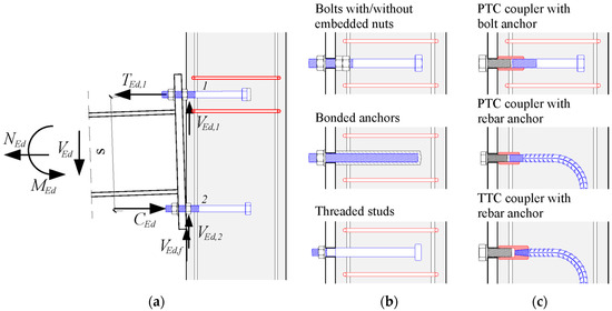
Figure 1.
Steel-concrete joints: (a) loads on each connector row, (b) traditional types of demountable connectors, (c) demountable connectors with mechanical couplers with different coupler and anchor types.
The performance of a steel-concrete structure highly depends on the performance of joints and connections between steel and concrete elements. The behavior of steel-concrete joints can have a significant effect on the distribution of internal forces and moments within the structure, as well as on the overall deformations of the structure. In general, joints can be classified as simple (pinned), continuous, or semi-continuous [5]. The performance of the joint can be evaluated through its resistance, rotational stiffness, and rotation capacity. The analysis of the overall behavior of steel-concrete joints and connections can be conducted via the component method [6,7], which is primarily used for the joint analysis in steel structures [8,9]. In order to predict the global resistance and deformability of joints and connections under arbitrary loads, the resistance and deformability of each component have to be determined (see Figure 1a). The “weakest” component mostly governs the behavior of the connection as a whole. Steel element transfers bending moment, shear, and axial forces to RC element as shear and axial loads acting on connectors. In the analysis of connectors, the key challenge is to define their behavior under pure shear load and pure tension load as well as under their combined action.
Most of the available research on the demountable connectors presented in Figure 1a,b was conducted under pure shear load in composite steel-concrete connections. The results have shown that threaded studs and bolted connectors without embedded nuts have comparable shear resistance and lower shear stiffness compared to welded headed studs [10,11,12]. The addition of one or two embedded nuts significantly improved the shear stiffness of the connectors [12,13,14]. Tan et al. [15] investigated the behavior of threaded studs in thin RC elements under pure shear and pure tension loads, as well as under combined loads. Specimens failed due to shank failure under pure shear while concrete splitting occurred under pure tension. Wang et al. [16] investigated the behavior of bolts with a single embedded nut and welded studs in ultra-high performance concrete under combined shear and tension loads and obtained similar results. In general, it is assumed that the behavior of traditional demountable headed connectors under tension load corresponds to the behavior of welded studs [17,18]. Therefore, for short connectors in low strength and normal strength concrete, cone failure could occur, and it is necessary to provide supplementary reinforcement [7]. In the same conditions, supplementary reinforcement is necessary for bonded anchors as well [19].
Although the application of the aforementioned connectors enables the reuse of steel and RC elements, the possibility of reuse or replacement of other components of the connection is limited. Bolted connectors and threaded studs cannot be replaced while there is a risk of physical damage to the exterior threaded portion of the connector during the assembly, building service life, and disassembly of structural components. This would preclude the possibility of reuse of the connection itself.
The new generation of bolted connectors with mechanical couplers is shown in Figure 1c. This type of connector consists of a mechanical coupler embedded in an RC element, anchored by an embedded bolt anchor or rebar anchor, as shown in Figure 1c. Most often, mechanical couplers have either parallel threads (PTC) or taper threads (TTC) for connection with the anchor. The steel element is connected to the RC element by installing the demountable bolt into the coupler. These connectors can be easily dismantled, which could improve the sustainability of steel-concrete composite structures. At the same time, mechanical couplers provide a flat surface for the RC element at the place of the connector, making assembly and disassembly easier compared to other demountable connector solutions. Furthermore, if the “weakest” component of the connector is the demountable bolt, the possibility of reuse of all connection components can be assured.
In the past decade, research on the shear behavior of demountable connectors with mechanical couplers was conducted by a few research groups. Yang et al. [20] investigated the shear behavior of bolted connectors with PTC mechanical couplers and bolt anchors in push-out tests (see Figure 1c). All specimens failed due to shear failure of the demountable bolt, and the results indicated that shear resistance and stiffness were comparable to bolted connectors with embedded nuts. After testing one specimen series, authors reused RC elements to assemble additional specimens. Reused specimens had practically the same shear resistance as the original specimens. Kozma et al. [4] and Nijgh et al. [21] investigated the behavior of the same connector type. Composite beams with oversized bolt holes in steel elements and prefabricated concrete decks were used in order to improve the execution efficiency. Oversized holes were injected with epoxy resin and steel-reinforced epoxy resin. All specimens failed due to shear failure of the demountable bolt. The results indicated that shear resistance and stiffness were also comparable to bolted connectors with embedded nuts, while slip at failure was significantly larger due to penetration of bolt threads into the epoxy resin. Since the connectors were anchored with embedded bolts, it is reasonable to assume that tension behavior would be similar to the behavior of welded-headed studs, and supplementary reinforcement is needed for short connectors.
The behavior of connectors with PTC couplers and headed rebar anchors in precast RC column-to-foundation joints under shear load was investigated by Yrjölä and Bujnak [22]. Although demountable bolts were subjected to the shear load with a lever arm, due to the grouting of the gap between the column and the foundation, the connection showed good performance with significantly higher resistance than predicted by design codes. Zhou et al. [23] investigated the behavior of demountable precast bridge RC piers-to-foundation connection realized by connectors with PTC coupler and rebar anchor, shown in Figure 1c. Reinforced concrete piers were subjected to cyclic load, i.e., connectors were subjected to combined shear and tension load. All specimens failed due to fracture of threaded part rebar anchors at the connection with the mechanical coupler.
Milosavljević et al. [24] and Milićević et al. [25] investigated the shear behavior of bolted connectors with TTC mechanical couplers and rebar anchors, as shown in Figure 1c. Experimental and numerical analyses were conducted on push-out test specimens. One of the main aims of the research was to investigate the shear behavior of connectors with a mechanical coupler located close to the concrete edge, with the shear load acting parallel to the concrete edge. This layout corresponds to steel beam-to-RC column/wall or steel column-to-RC foundation connections. In order to define failure modes and the corresponding resistance and deformability of the connection, concrete edge distance, concrete strength, and connector diameter were varied. Authors concluded that concrete edge failure occurred when connectors are located close to the concrete edge in low strength and normal strength concrete. Prediction equations for concrete edge failure resistance were proposed. When connectors were located far from the concrete edge, bolt shear failure occurred.
Previous research provided many answers regarding the shear behavior of the demountable connectors with mechanical couplers and insight into the possibility for reuse of connection components. However, for practical implementation of this type of connector, it is necessary to define its behavior under combined shear and tension loads. In this regard, understanding the actual behavior of the connector under pure tension load is crucial, since there are no clear recommendations in design codes nor in experimental studies. The tension behavior of connectors with mechanical couplers and rebar anchors is more complex than other types of connectors because these connectors are assembled from three different elements (bolt, coupler and rebar) with different geometrical characteristics and steel mechanical characteristics, i.e., yield and ultimate tensile strength and corresponding strains. It is assumed that the component method can be extended to the local analysis of the connector. Through adequate anchoring of the connector with a rebar anchor according to EN 1992-1-1:2004 [26], all concrete failure modes can be reduced to a minor concrete damage or even be excluded. Understanding the concrete component when the connector is loaded in tension is very important, since the connector can be anchored with a rebar anchor only, i.e., without any supplementary reinforcement.
The aim of this paper is to provide insight into the behavior of a steel-concrete connection with a demountable connector with a mechanical coupler and rebar anchor under a tension load, in terms of resistance and deformability, as well as their potential for reuse. In the following, four specimen series with single connectors embedded in RC elements were investigated in pull-out tests. Concrete strength, connector diameter, and bolt grade were varied. In addition, two specimen series of bare connectors were tested in in-air tests. The failure modes, tension resistances, load-deformation curves, deformation capacities, and stiffnesses were examined and compared mutually. Based on test results, simplified equations for estimating tension resistance and load-deformation curves are proposed.
2. Experimental Tests
2.1. Connector Configuration and Experimental Approach
To obtain detailed insight into the behavior of the demountable connector with a mechanical coupler and rebar anchor under a tension load, experimental testing was conducted in two phases: (1) testing of pull-out specimens and (2) testing of in-air specimens. The pull-out specimens were tested in order to obtain the global behavior of the connection, while in-air specimens were tested for detailed insight into the local behavior of the connector itself. The same diameters and similar configurations of the connectors were chosen as connectors used for push-out tests conducted by Milosavljević et al. [24]. The layout of the connectors with M20 and M16 bolts with taper threaded couplers (TTC) is shown in Figure 2.
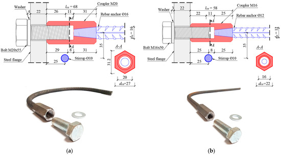
Figure 2.
The layout of tested demountable connectors with mechanical coupler and rebar anchor: (a) connector with M20 bolt and 16 mm rebar anchor, and (b) connector with M16 bolt and 12 mm rebar anchor.
2.2. Pull-Out Tests
2.2.1. Experimental Program and Test Set-Up
The experimental program of pull-out tests presented in this paper is shown in Table 1. Test specimens were divided into four series, which differ in connector diameter, nominal concrete compressive strength, and bolt grade. The values of all parameters were determined to match as much as possible to push out test specimens analyzed by Milosavljević et al. [24] and Milićević et al. [25]. In this regard, a concrete edge distance of c = 75 mm was adopted for all pull-out specimens in order to investigate the tensile behavior of the bolted connection with a mechanical coupler, which exhibited concrete edge failure under shear load [24,25]. The same reasoning was the base for the adoption of concrete class (C20/25 and C30/37), as well as the different connector diameters (with M16 and M20 bolts). Lastly, bolt grade was varied between specimen series A-T and D-T (grade 8.8 and grade 5.8). Only one specimen was tested within series D-T, which was considered sufficient to detect a 10% resistance variation compared to specimen series A-T. In total, 9 specimens were tested in pull-out tests.

Table 1.
Program of pull-out tests.
The layout of specimens for pull-out tests is shown in Figure 3. Test specimens were assembled from one built-up steel element connected to a precast reinforced concrete element. The connection was achieved by connecting the demountable bolt to the embedded mechanical coupler and rebar anchor. Bolts were pretensioned with pretension force in the range of 15–20 kN, based on bolt diameter and grade (approximately 20% of actual full pretension force), in order to achieve the same conditions in all specimens with small pretension. The dimensions of RC elements and reinforcement detailing were similar to the specimen layout used for push-out tests by Milosavljević et al. [24]. In this research, the dimensions of RC elements were Dc/Bc/Hc = 300/500/600 mm for all test specimens. Two connectors were placed in one RC element; however, the pull-out testing was performed on only one connector at a time. The connectors were placed in the middle of the RC elements in order to assure load symmetry.
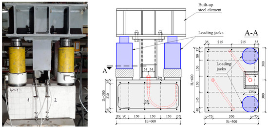
Figure 3.
The layout of experimental pull-out test specimens.
The shape and dimensions of rebar anchors are determined based on the required anchorage length for the expected tension load and limited dimensions of the RC element. The anchorage lengths were determined according to EN 1992-1-1:2004 [26], as a function of the measured yield strength of rebar anchors fy,a and the measured mean compressive cylinder strength fcm for specimens with concrete class C20/25. The mandrel diameters were also determined according to EN 1992-1-1:2004 [26], in order to avoid concrete side failure considering geometrical and mechanical characteristics of tested specimens. In this regard, connectors with M20 bolts and 16 mm rebar anchors have two bents with a mandrel diameter of Dm = 250 mm, while connectors with M16 bolts and 12 mm rebar anchors have only one bent with a mandrel diameter of Dm = 150 mm (see Figure 2).
2.2.2. Loading and Measurement Procedures
Following the specimen assembly, two loading jacks were placed between the RC element and the steel element, as shown in Figure 4. Loading jacks were placed symmetrically in relation to the connector axis, at the centroidal distance of 225 mm. In this way, the tension load was applied centrically on the connection. Two loading cells were placed at the bottom of loading jacks in order to continually measure the applied tension load. Loading cells were supported by two steel plates with 20 mm thickness. At the top of the loading jacks, two spherical bearings were placed.

Figure 4.
Sensor layout for pull-out tests.
The loading procedure was completed in two phases, similarly to the procedure described in [15,27,28]. In the first phase, monotonic tension load was increased gradually for not less than 20 min, up to the attainment of connector yield strength Ty. On average, this corresponds to an increase in tension load up to 4.5 kN/min (an increase in uplift dT up to 0.05 mm/min). In the second loading phase, the specimen was loaded until the failure for not less than 15 min. The load was applied with 400 kN capacity loading jacks.
During the testing of all specimens, measuring of displacements was performed with four linear variable differential transducers (LVDTs). Only the uplift of the steel element from the RC element was measured at places T1–T4, as shown in Figure 4. The uplift at the outer side of the specimens was measured at places T1 and T2, while the uplift at the middle of the specimen was measured at places T3 and T4. This layout of LVTDs provided the measurement not only of the steel-concrete uplift but also the potential rotation of the steel element about both horizontal axes. The T1 and T2 transducers were placed in such a manner that avoids possible disturbance of uplift measurement due to the possibility of concrete edge failure appearing on the side surface of the RC element. Similarly, the T3 and T4 transducers were placed far from the connection due to possible concrete damage at the steel-concrete interface. It should be noted that measuring the uplift alone in the pull-out test does not provide insight into local deformations of connector components. However, pull-out test results will be supplemented with in-air test results for a comprehensive analysis of the connection behavior in Section 4.
2.3. In-Air Tests
2.3.1. Experimental Program and Test Set-Up
In order to analyze the local behavior of demountable connectors with a mechanical coupler under a tension load, tensile testing of in-air specimens was conducted on the same connectors tested in pull-out tests. Two specimen series were tested: (1) specimen series CON M20/D16 with M20 bolts and 16 mm rebar anchor (see Figure 2a), and (2) specimen series CON M16/D12 with M16 bolts and 12 mm rebar anchor (see Figure 2b). In both cases, bolts with nominal grade 8.8 were used. Both specimen series contained 3 specimens (6 specimens in total).
The layout of in-air specimens is presented in Figure 5. Specimens were assembled by connecting the steel fixture to the mechanical coupler with a steel bolt. Specimens with fixtures were placed in the tensile testing machine. The testing machine was provided with high pressure grips that restrain the clamped specimen regions—fixture on one side and rebar anchor on the other side, without permitting any slip. In all cases, specimens had a minimum clear length of rebar anchor lcl = 300 mm. As in push-out tests, bolts were pretensioned with a low level of pretension force.
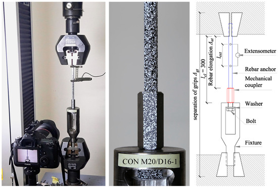
Figure 5.
The layout of experimental in-air test specimens.
2.3.2. Loading and Measurement Procedures
In-air tests were carried out in a Shimadzu tensile testing machine provided with a capacity of 300 kN for static load. Loading of in-air specimens was conducted in displacement control mode with a 1.0 mm/min stroke rate until failure. The total time of each tension test was not less than 35 min, as in the case of pull-out tests.
The testing machine provided the measurement of tension force T and separation of grips Δgt. The elongation of the rebar anchor and corresponding strains εa were measured by an extensometer with a gauge length lext = 100 mm, as shown in Figure 5. All data were measured with a frequency of 1.0 Hz.
The local deformations, strain localization, and fracture of connector parts were measured using the Digital Image Correlation (DIC) method. The front of the specimens was painted in high contrast black and white patterns, as shown in Figure 5. Firstly, water-based white paint was applied, and, subsequently, a fine black speckle random pattern was applied. The measurement of physical quantities was performed every 10 s (with a frequency of 0.1 Hz). All displacements at measurement points were measured on the axis of the connector. The details regarding specimen preparation, testing and measurement procedures, as well as the control of the obtained results, for preliminary testing of demountable connectors with M20 bolts under tension load are presented in [29]. DIC analysis on recorded images was done using an opensource 2D MATLAB program—Ncorr (https://www.ncorr.com/) and free version of GOM Correlate software.
The layout of measurement points and corresponding physical quantities that were measured in in-air tests are presented in Figure 6. The quantities were adopted as the most appropriate for a detailed description of the local behavior of all connector components under tension load. All measured deformations of the connector were based on the difference of connector displacements at points 0–4. The elongation of the rebar anchor and corresponding strains εa were measured based on the available lengths on photographs—90 mm for connectors with M20 bolts and 100 mm for connectors with M16 bolts. The elongation of mechanical couplers Δco was measured at the location of the weakest section (section I-I in Figure 2). The slip between the rebar anchor and mechanical coupler slip Δaco was calculated based on the displacement difference between adjacent points on the rebar and coupler. Bolt elongation Δb was estimated with the neglection of deformation of the bolt head and washer. Lastly, the total elongation of the connectors was assessed based on the displacement dt,L. This point was determined based on the length of the straight part of rebar anchors used for connectors tested in pull-out tests (L = 50 mm for connectors with M20 bolts and L = 110 mm for connectors with M16 bolts, as shown in Figure 2 and Figure 6).
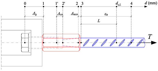
Figure 6.
Schematic layout of measured physical quantities of interest for in-air tests.
2.4. Material Properties
Material properties of key components for pull-out and in-air specimens (i.e., concrete, steel bolts, couplers, and rebar anchors) were obtained through standardized procedures. Statistical evaluation of test results was performed according to propositions given in EN 1990: 2002, Annex D [30]. At least three test samples of each material were tested.
The compressive strength of concrete fcm,cube was determined on standard concrete cubes 150 × 150 × 150 mm, while the modulus of elasticity of concrete Ecm and concrete tensile (splitting) strength fctm,sp were determined based on cylinder tests. Test samples were cured in the same condition as concrete elements for pull-out tests and were tested on the same day, as shown in Table 2. Concrete compressive cylinder strength fcm and modulus of elasticity Ecm were calculated based on tested strength fcm,cube according to EN 1992-1-1:2004 [26], while tensile strength fctm was calculated based on splitting strength fctm,sp.
Table 2.
Mechanical properties of concrete.
Steel components of the connector used both for pull-out tests and in-air tests were from the same batch. Steel coupons taken from bolts and walls of mechanical couplers were made following the recommendations given in EN ISO 6892-1 [31]. Reinforcement samples used for rebar anchors were tested following the recommendations given in EN ISO 15630-1 [32]. Three samples of each material for connector component were tested. The obtained stress-strain curves are shown in Figure 7, while material properties such as yield strength fy, ultimate strength fu, modulus of elasticity E, and strain after fracture εf are listed in Table 3. Steel S355 was used for the built-up steel element used in pull-out tests and was not tested since the steel element remained elastic after tests. Also, reinforcing steel B500B was used for 10 mm reinforcement of RC elements.
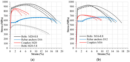
Figure 7.
Stress-strain curves for all connector components: (a) components of connectors with M20 bolts, (b) components of connectors with M16 bolts.
Table 3.
Mechanical properties of steel components.
3. Experimental Test Results
3.1. Pull-Out Tests
3.1.1. Failure Modes
Damage of pull-out specimens after testing is presented in Figure 8. All pull-out specimens failed due to connector failure in tension. This failure mode was predetermined since the size of the mandrel diameter was calculated to avoid concrete side failure. Regarding the connector tension failure, two different local failure modes were observed: (1) failure of rebar-coupler connection and (2) failure of demountable bolt.

Figure 8.
Failure modes and damage of RC elements: (a–c) A-T specimen series, (d) B-T specimen series, (e) C-T specimen series, (f) D-T specimen series with M20 bolt (grade 5.8).
Failure of the rebar-coupler connection occurred in all test specimens with bolt grade 8.8., i.e., specimens A-T, B-T, and C-T (as shown in Figure 8a–e). After testing the specimens and removing mechanical couplers, stripping failure of taper threads on the rebar anchor was detected inside the mechanical coupler. Also, spalling of concrete at the bottom side of the mechanical coupler was observed. The same failure mode was observed by Chiari and Moreno Junior [33] after testing of reinforcement splices with taper threaded couplers. On the other hand, bolt failure occurred only in specimen D-T (with bolt grade 5.8), without significant damage to the embedded part of the connector.
During experimental testing of pull-out specimens, the crack development and propagation on the outer side of the RC element were visually tracked, as shown in Figure 8. Compared to other specimen series, test specimens in series A-T had the largest level and extent of concrete damage. Figure 8b shows a typical crack pattern on the outer side of the specimens in series A-T, with only one barely visible (splitting) crack. Crack development on the outer side of the RC element started shortly before the attainment of the connector yielding load. These cracks have propagated up to the attainment of the ultimate load to the lower side, i.e., the middle part of the rebar anchor bent. At the front side of RC elements, the breakout of a small concrete cone occurred due to the loss of bond between the connector and surrounding concrete. Similar damage to concrete was observed after pull-out tests of bonded anchors by Delhomme et al. [27]. Concrete cracks did not appear on specimens in series B-T and C-T, with higher concrete strength and small connector diameter, respectively.
3.1.2. Load-Uplift Behavior
The results of pull-out tests are presented in Figure 9 in terms of tension load applied to the connector T and the uplift between steel and RC elements dT. The values of uplift dT were determined at the position of the bolt in the transverse direction of specimens, based on measured values of uplift at the location of T1–T4 LVDTs (see Figure 4). This assumption was justified since the difference of measured uplifts at measurement places T1–T4 (rotation about both horizontal axes) was proved to be practically insignificant.

Figure 9.
Tension load-uplift curves from pull-out tests: (a) specimen series A-T, (b) specimen series B-T, (c) specimen series C-T, (d) all tension load-uplift curves.
The main parameters describing the specimen behavior under tension load (i.e., tension load T and uplift dT) at different loading phases are presented in Table 4. Statistical evaluation of test results was performed according to recommendations given in EN 1990:2002, Annex D [30], in cases where at least three test specimens were tested.
Table 4.
Results of pull-out tests.
The pull-out test results have shown that the diameter of the connector as well as the bolt grade had a significant effect on the tension resistance and deformability of the connection. For specimens in series A-T and B-T (M20 bolts, grade 8.8), the average tension resistance of the connection Tu was equal to 134.7 kN. The average tension resistance for specimens in series C-T (M16 bolts, grade 8.8) was 77.0 kN, i.e., 43% less than the resistance of series A-T and B-T. The difference of ultimate loads between these series corresponds to the different tension resistance of rebar anchors with diameters of 16 mm and 12 mm. Tension resistance of specimen D-T (M20 bolt, grade 5.8) was 127.0 kN, which is 6% less than the average resistance of specimens A-T and B-T (M20 bolts, grade 8.8).
Higher initial stiffness of the connection (see Figure 9d) was the result of a small amount of bolt preload, as stated in Section 2.2.1. After the bolt preloading force was overcome, there was a drop in connection stiffness. Distinctly non-linear behavior of the connection occurred at around 85% of the ultimate resistance. This phase was identified with the yielding load of the connector Ty, i.e., yielding rebar anchor in case of specimens with bolts grade 8.8 and, in case of specimen D-T, yielding of bolt grade 5.8. The steel-concrete uplift in this phase was between 0.6 and 1.4 mm. The failure of all specimens occurred at the uplift not less than 6.5 mm. Specimens in series B-T had the lowest deformability due to the highest concrete strength, while specimen D-T had the highest deformability, primarily due to bolt failure.
3.2. In-Air Tests
3.2.1. Failure Modes
As stated in Section 2.3.1, in-air specimens were assembled by connecting a demountable bolt to a mechanical coupler and rebar anchor, with corresponding diameter and mechanical characteristics. Since bolts with grade 8.8 were used, there were two possible failure modes: rebar anchor failure and failure of connection between rebar anchor and mechanical coupler realized with taper threads.
All in-air specimens loaded in tension failed due to failure of the connection between the rebar anchor and mechanical coupler realized with taper threads. This failure mode was also observed after examination of pull-out specimens after testing (see Section 3.1.1). Damage of characteristic in-air specimen after testing is presented in Figure 10. It can be noticed that failure occurred due to stripping of taper threads at the end of rebar anchors, as shown in Figure 10b. This failure mode was also observed after in-air tests of taper threaded spliced reinforcement loaded in tension by Chiari and Moreno Junior [33].
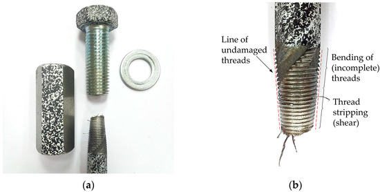
Figure 10.
Failure mode of in-air specimens: (a) typical layout of specimen after testing, (b) failure mode of rebar anchor-to-mechanical coupler connection.
After detailed examination of taper threads at the end of rebar anchors, it was concluded that this failure mode prevailed due to incomplete threading on the upper part of the anchor, used for connection with a mechanical coupler. While the lower part of the tapered threaded end failed in shear, the damage of the upper part was characterized by bending of incomplete threads. Incomplete threading was the result of the manufacturing process of cut threading on ribbed (deformed) bars. It should be noted that threads inside the mechanical coupler remained undamaged. Mechanical couplers, as well as demountable bolts, remained undamaged (see Figure 8a).
3.2.2. Load-Deformation Behavior
The results of in-air tests are presented in Figure 11 and Figure 12 in terms of tension load applied to the connector and deformations of different parts of the connector. These deformations and measurement procedures were defined in Section 2.3.2. The strain distribution of connector parts at characteristic loading stages, measured via the DIC method, is also shown in figures.
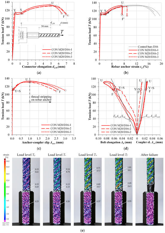
Figure 11.
In-air test results for CON M20/D16 specimen series (bolt grade 8.8): (a) load-elongation curve for connector, (b) load-strain curve for rebar anchor, (c) load-slip curve for connection between rebar anchor and mechanical coupler, (d) load-elongation curve for bolt and mechanical coupler, (e) strain distribution in connector parts at different loading phases.
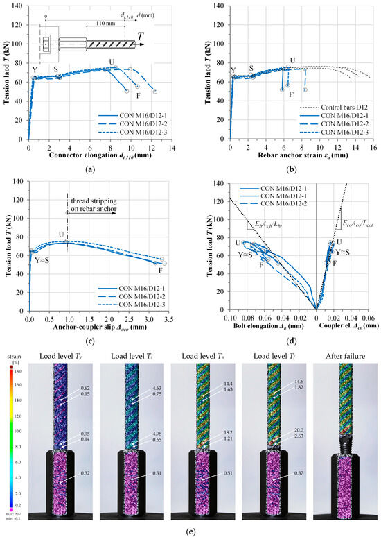
Figure 12.
In-air test results for CON M16/D12 specimen series (bolt grade 8.8): (a) load-elongation curve for connector, (b) load-strain curve for rebar anchor, (c) load-slip curve for connection between rebar anchor and mechanical coupler, (d) load-elongation curve for bolt and mechanical coupler, (e) strain distribution in connector parts at different loading phases.
The main parameters describing the specimen behavior under tension load (i.e., tension load T, elongation of the connector dt, and slip between rebar anchor and mechanical coupler Δaco) at different loading phases are presented in Table 5. Statistical evaluation of test results was performed according to recommendations given in EN 1990: 2002, Annex D [30].
Table 5.
Results of in-air tests.
As previously stated, failure of all tested specimens occurred due to failure of the taper threaded connection between the rebar anchor and the mechanical coupler. The average tension resistance Tu was equal to 131.7 kN for specimen series CON M20/D16, while the average tension resistance Tu was equal to 74.0 kN for specimen series CON M16/D12. As shown in Figure 11b and Figure 12b, tension resistance of tested connectors was up to 2% less than the tension resistance of corresponding control bars.
The global behavior of the connectors under tension load was similar for both specimen series. The behavior of the rebar anchor was governing the behavior of the connector as a whole, which can be explained with significantly higher strains in the rebar anchor compared to the strain in the mechanical coupler, as shown in Figure 11e and Figure 12e. Therefore, four characteristic loading phases for describing connector behavior can be defined: “Y”—onset of rebar anchor yielding, “S”—onset of rebar anchor strain hardening, “U”—ultimate resistance of rebar anchor (connector), and “F”—failure of the connector.
As shown in Figure 11e and Figure 12e, the maximal strains in the mechanical coupler are located at the middle of the coupler, i.e., the transition from the demountable bolt to the rebar anchor (section I-I in Figure 2). Tension load-coupler elongation curves at that location are shown in Figure 11d and Figure 12d. In both cases, mechanical couplers have approximately elastic behavior up to failure of the connectors, and a good match between measured stiffness and theoretically obtained stiffness can be observed. Similarly, the behavior of bolts was approximately elastic. Higher initial stiffness can be attributed to the low pretension (see Section 2.3.1). After testing, the bolt was easily demounted from the coupler (see Figure 10a).
As previously stated, the behavior of the connector was governed by the behavior of the rebar anchor up to the ultimate load (part 0-U). This can be noticed in Figure 11a,b and Figure 12a,b). The attainment of ultimate load corresponds to the onset of taper thread stripping at the end of the rebar anchor inside the mechanical coupler, prior to rebar anchor necking. As a result, slip between the rebar anchor and coupler Δaco increased until failure (part U-F on Figure 11 and Figure 12). In all cases, part U-F on presented curves was practically the same, since there was no additional increase of strains in rebar anchors (part U-F’). On average, total elongation of connectors at fracture load in series CON M20/D16 was dt,50 = 6.85 mm, while total elongation of connectors in series CON M16/D12 was dt,110 = 10.85 mm. It should be noted that these elongations were measured on different lengths of the connector in order to adequately compare the results of in-air tests with pull-out test results (see Section 2.3.2).
ISO 15835-1 standard for reinforcement splices with mechanical couplers [34] requires that tested splices have at least 8% higher strength than the measured yield strength of the reference bar with ductility class B according to EN 1992-1-1:2004 [26]. The lowest value measured ultimate tensile strength of connector Tu,a was equal to 130.6 kN and 73.2 kN for connectors with M20 bolts (16 mm rebar anchor) and connectors with M16 bolts (12 mm rebar anchor), respectively. These values of tensile strength are 18% and 11% higher than the average yield strength of the corresponding reference bars, respectively. Therefore, the condition for minimum tensile strength of connection according to ISO 15835-1 is fulfilled.
Similarly, the ISO 15835-1 standard requires that total elongation of reinforcement outside of the length of splice under ultimate load be at least 70% of specified characteristic strain (i.e., εa,uk = 5% for reinforcement ductility class B, according to EN 1992-1-1:2004 [26]. Measured rebar anchor elongation εu,a,con for all tested specimens fulfilled this requirement (see Table 5).
As presented in Figure 11c and Figure 12c, the values of anchor-coupler slip Δaco,u (part 0-U) are approximately equal to 1.0 mm. This indicates that there was an elongation at the end of the rebar anchor inside the coupler due to incomplete threading and the reduction of the cross-section. However, the average values of anchor-coupler slip Δaco,y (part 0-Y) are less than 0.05 mm (see Table 5). Therefore, the requirement Δaco,0.6Ty ≤ 0.05 mm under a tension load equal to 0.6Ty, given for reinforcement splices with mechanical couplers in ISO 15835-1 [34], is fulfilled in all cases.
4. Discussion
4.1. Comparative Analysis of Test Results
Based on experimental test results, the global behavior of the demountable connection with a taper-threaded mechanical coupler and rebar anchor under a tension load will be defined in terms of tension resistance and deformability, i.e., stiffness and uplift capacity (ductility). This section provides the analysis of these parameters based on connector diameter, concrete strength, and demountable bolt strength. In order to provide detailed insight into the behavior of the connection as a whole, pull-out test results are compared to in-air test results.
4.1.1. Resistance of the Connection Under Tension Load
The comparative analysis of mean yield resistance Ty and ultimate resistance Tu for pull-out test results, in-air test results, and control bar test results is presented in Figure 13. In the case of bolt grade 8.8, failure of the connector was governed by failure of the rebar-coupler connection. However, in this case, pull-out test results indicate slightly higher resistance than in-air test results (up to 4%) and control bar test results (up to 2%). This can be attributed to the tension stiffening and lever arm between the tension load and reaction force in concrete inside the bend, as explained in [35,36]. In the case of bolt grade 5.8, yield resistance and tension resistance were both less than the corresponding resistance of control bars and in-air specimens. In this case, the pull-test resistance of specimen D-T equal to Tu = 127.0 kN showed good agreement with the calculated ultimate resistance of the bolt Tu,b = As,b·fu,b = 122.9 kN (As,b is the tensile stress area equal to 245 mm2, fu,b is the measured bolt strength equal to 501.7 MPa, as given in Table 3). The difference between calculated and measured resistances can be explained by the aforementioned reasons.
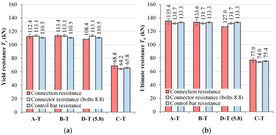
Figure 13.
Comparative analysis of test results under tension load: (a) mean yield resistance, (b) mean ultimate resistance (error bars are showing the full range of obtained resistances within the specimen series).
4.1.2. Deformability of the Connection Under Tension Load
Deformability of the connection will be defined in terms of stiffness and the capacity of uplift between steel and the RC element.
In order to closely evaluate stiffness of the connection, three phases will be considered: initial stiffness kT,in, stiffness at serviceability load kT,s (70% of the ultimate load), and stiffness at yield load kT,y. Mean values of connection stiffness for each specimen series are presented in Table 6. It can be noticed that stiffness of connection decreases from initial stiffness kT,in to stiffness at serviceability load kT,s by 13% on average, while decrease of stiffness from kT,in to stiffness at yield load kT,y on average is equal to 25%. The largest decrease of stiffness was exhibited in specimens in the C-T series, with lower concrete strength and lower Dm/da (mandrel diameter-to-rebar anchor diameter) ratio, while the smallest decrease of stiffness was exhibited in specimens in the B-T series, with higher concrete strength and higher Dm/da ratio. Similar behavior in pull-out tests of straight ribbed bars embedded in concrete (fcm(t) = 52.3 MPa) was obtained by Delhomme et al. [27]. It should be noted that hooked bars have lower stiffness than straight bars [36].
Table 6.
Comparative analysis of connection stiffness under tension load.
The results indicate that there is a large effect of concrete strength on the stiffness of the connection for the same bolt diameter and grade (series A-T and B-T). The increase of concrete strength fcm(t) from 24.9 MPa to 39.4 MPa leads to an increase of stiffness in all load phases in the range of 47–60%. Minor [36] obtained similar differences in stiffness after testing short, hooked bars embedded in concrete, albeit with smaller mandrel diameters compared to mandrels used in this study. Further investigations are needed to obtain the effect of the increase of concrete strength on connection stiffness in order to define the threshold after this effect diminishes. The reduction of bolt strength grade from 8.8 to 5.8 leads to a decrease of stiffness in all load phases in the range of 10–15%. The reduction of connector diameter leads to a decrease of stiffness at serviceability and yield load of approximately 11%.
Figure 14 presents the comparison between mean values of uplift dT, obtained from pull-out tests, with mean values of corresponding connector elongation, obtained from in-air tests. All values are defined for load phases Y (yield load), S (strain hardening), U (ultimate load), and F (failure load).

Figure 14.
Comparative analysis of uplift (pull-out tests) with elongation of connector (in-air tests).
At yield load (phase Y), it can be noticed that the uplift between steel and RC elements was larger than the corresponding elongation obtained from in-air tests. This can be explained with a larger total elongation length of the rebar anchor in RC concrete and damage to the concrete inside the anchor bend. Unlike, uplift was significantly lower than the elongation of the corresponding connector in the Y-S part, which can be attributed to the tension stiffening effect in pull-out tests. Similar behavior in pull-out tests of straight ribbed bars embedded in concrete was obtained by Delhomme et al. [27]. For pull-out test specimens with bolt grade 8.8, the higher concrete strength and smaller connector diameter resulted in a decrease of the uplift at ultimate load by 18% and 9%, respectively. A similar effect of compressive strength on the slip of hooked anchorages was also observed by Minor [36]. Specimen D-T, with bolt grade 5.8, had 19% lower uplift than mean value of uplift for specimen series A-T, due to lower ultimate load and smaller elongation length of demountable bolt compared to rebar anchor. At failure, specimen D-T exhibited significantly larger ductility than all other pull-out test specimens, due to failure of the demountable bolt (grade 5.8).
4.2. Design Recommendations
The analysis of demountable connectors with mechanical couplers and rebar anchors can be conducted via the component method in a similar manner as for the analysis of steel-concrete joints and connections. Figure 15 shows the application of the component method for the analysis of demountable connectors with a mechanical coupler and rebar anchor in steel-concrete connections. Bending moment, shear, and axial forces acting on steel elements are transferred to RC elements as shear and axial loads acting on connectors. When connectors are subjected to a tension load (with negligible shear load), the tension behavior of the “weakest” component of the connector governs the behavior of the connector as a whole.
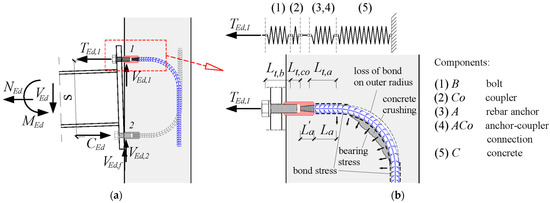
Figure 15.
Application of the component method for demountable connectors with TTP mechanical couplers and rebar anchors in steel-concrete connections: (a) joint subjected to bending moment, axial load, and shear load, (b) components of the connector under tension load (shear load neglected).
Figure 15b shows a representative (simplified) model for the analyzed connector composed of springs and rigid links in series. Each spring corresponds to a particular component of the connector: demountable bolt (B), mechanical coupler (Co), rebar anchor (A), anchor-coupler connection (ACo), and concrete (C).
Tension resistance of the connector is determined based on the lowest value of tension resistances of each component. The overall deformability of the connection (stiffness and deformation capacity) depends on several mechanisms: (1) elongation of demountable bolt, (2) elongation of mechanical coupler, (3) elongation of taper threaded rebar anchor end inside mechanical coupler, (4) slip between rebar anchor and surrounding concrete, as well as the elongation of rebar anchor itself, and (5) concrete damage inside rebar anchor bent. According to Minor [36], with increasing tension load, bond stress between the straight part of the rebar anchor and the surrounding concrete decreases due to an increase in the slip. This effect is more pronounced for the short straight part of the bar, which is the case in this research. At the same time, concrete crushing inside the anchor bent occurs, while outside of the bent, the anchor bar is pulled away from the concrete, thus diminishing the bond on the outer radius (Figure 15b).
In order to prevent concrete failure, the anchorage length and shape (mandrel diameter) of the rebar anchor should be determined according to EN 1992-1-1:2004 [26] in order to prevent side blow-out failure and reduce concrete damage inside the anchor bent. Therefore, tension resistance can be evaluated based solely on the resistance of the connector components (bolt, mechanical coupler, and rebar anchor). The overall deformability of the connector (i.e., stiffness and deformation capacity) depends on the deformability of each component as well as their interaction under the yield and ultimate tension resistance of the governing component of the connector.
Tension resistance of the connector as a whole, Tcon can be defined as given in EAD 330012-00-0601 [37]:
where Tb, Tco, Ta, and Taco are tension resistances of demountable bolt, mechanical coupler, rebar anchor, and anchor-coupler connection, respectively. Tension resistance of the connector can be defined at the yield phase Ty,con and the ultimate phase Tu,con.
In this paper, simplified prediction equations for the determination of tension resistance and deformability of each component of the connector are presented in Table 7. The resistance and deformability are defined for yield and ultimate phases, with the assumption of bilinear stress-strain curves of steel components, with an inclined branch from yield stress fy to ultimate stress fu, defined for each steel component. Cross-section area As is tensile stress area for bolts As,b, tensile stress area of hollow hexagonal section for mechanical couplers As,co, and nominal gross cross-sectional area of rebar anchor As,a. It should be noted that, for clarity reasons, notations of some parameters are different than those defined in design standards and recommendations [26,37,38].
Table 7.
Prediction equations for mean resistance and deformation capacity for each component of the demountable connector with TTP mechanical coupler and rebar anchor under tension load.
Elongation lengths of demountable bolt Lt,b, mechanical coupler Lt,co, and rebar anchor Lt,a are defined in Figure 15b. It was assumed that the connection between the rebar anchor and the mechanical coupler does not affect the tension resistance of the rebar anchor, as proven by the test results presented in Section 3. Therefore, the tension resistance of the anchor-coupler connection Taco was adopted as equal to the resistance of the rebar anchor Ta. However, in-air test results indicated that there is an effect of the anchor-coupler connection on the connector deformation. This effect was taken into account by increasing the elongation length of the straight portion of the rebar anchor to Lt,a = La + La’/3 (see Figure 15b). Furthermore, for simplicity reasons, the bond between the rebar anchor and concrete was neglected. More detailed models for slip of straight reinforcing bars in tension can be found in EN 1994-1-1:2004 [5] and ECCS publication No. 109 [39]. These models were successfully implemented in the analysis of composite beam-to-RC wall joints by Henriques et al. [6]. However, due to the small length of the straight part of the bent rebar anchors adopted in this research, the aforementioned models are not fully applicable. It should be noted that the equations given in Table 7 are defined for determining resistance and deformation capacities for connector components (bolt, coupler, rebar anchor). For determination of actual uplift between steel and concrete elements, the deformation of each connector component should be calculated based on the connector resistance Tcon given in Equation (1), at yield and ultimate phases, following the defined bilinear stress-strain curves for each component.
As presented in Table 7, for component C, concrete bearing pressure pc inside anchor bent should be determined according to EN 1992-1-1:2004 [26], based on concrete edge distance to the connector (rebar anchor) axis c, rebar anchor diameter da, mandrel diameter of rebar anchor Dm, and tension resistance of connector as a whole Tcon, at yield and ultimate phases. This condition prevents concrete side blow-out failure implicitly and reduces concrete damage to a minor extent.
Minor [36] and Sperry et al. [40] reported that slip of hooked bars highly depends on deformation (crushing) of concrete inside bent and loss of bond on outer bent radius (see Figure 15b). Minor [36] noted that the slip of hooked bars was larger than the corresponding straight bars and highly depended on concrete strength (the square root of concrete strength) and mandrel diameter (the ratio of mandrel diameter to reinforcing bar diameter).
Based on experimental tests presented in this paper, a simplified empirical prediction equation for the calculation of the deformation of the connector with a mechanical coupler and rebar anchor due to concrete damage inside the anchor bent Δc was derived:
where Tcon tension resistance of the connector as a whole (in N) is given in Equation (1), fcm(t) is concrete compressive strength at the age of testing (in MPa), and Dm is the mandrel diameter of the rebar anchor (in mm). The values of coefficients α1, α2, and α3 were determined based on the regression analysis as α1 = 3800, α2 = 0.67, and α3 = 0.25. The set of key parameters (Tcon, fcm(t), and Dm) that affect the deformation of the connector due to concrete damage inside the rebar anchor bent in Equation (2) was chosen based on the requirement of EN 1992-1-1:2004 [26] for the shape of bent reinforcement in order to prevent concrete damage in the vicinity of the edge. Therefore, it was assumed that concrete edge distance c and anchor diameter da do not affect the deformation of the connector (see Table 7).
Following the prediction equations given in Table 7, the total deformation of the connection dT (uplift between steel and RC element) can be calculated at yield and ultimate phases as:
Experimental tension load-uplift curves (obtained from pull-out tests) and analytical tension load-uplift curves (obtained from prediction equations given in Table 7) are compared in Figure 16. Tension resistances and deformation capacities for each component and connection as a whole are given in Table A1 and Table A2, calculated based on equations given in Table 7 and Equations (1)–(3) for each specimen series. Ultimate strains εu,a,con, obtained from in-air tests, were used in prediction equations. It can be noticed that there is good agreement between test and analytical results. Average test-to-predict values of uplift between steel and RC element were 1.01 (CoV = 14.5%) at yield load and 0.91 (CoV = 19.5%) at ultimate load.
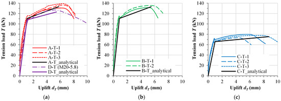
Figure 16.
Tension load-uplift curves comparing experimental and analytical results: (a) series A-T and D-T, (b) series B-T, (c) series C-T.
It should be noted that Equation (2) is only applicable if concrete damage is prevented, i.e., concrete side-blowout failure is prevented, and concrete damage inside the anchor bent is reduced to a minor extent. This can be achieved by determining the anchorage length and shape (mandrel diameter) of the rebar anchor according to EN 1992-1-1:2004 [26]. Furthermore, the Equation (2) is defined based solely on test results presented in this research, with concrete strength varied in range fcm(t) = 24.9–39.4 MPa. Therefore, further investigations are needed in order to more precisely define the effect of concrete strength on the contribution of concrete damage inside the anchor bent to the uplift of the connection. Moreover, for bent rebar anchors with a longer straight part, the effect of the bond between the rebar and the surrounding concrete could have a more significant effect and should be taken into account.
Following the rationale of the proposed design models, different types of demountable connectors with mechanical coupler and rebar anchor under tension load can be analyzed. This includes connectors with different ratio of bolt-coupler-anchor strength and different ratio of bolt-coupler-anchor diameter. In engineering practice, mechanical couplers are most often designed to have higher tension resistance than rebar anchors. Therefore, connectors with larger bolt diameter and strength than rebar anchor will ultimately fail due to rebar anchor failure (taper threaded stripping or bar failure), and vice versa.
In terms of ductility, it should be noted that relying upon bolt failure as a “source” of ductility of the connection is often precluded in design standards (e.g., EN 1993-1-8 [38]) due to potential overall brittle failure of the connection. The increase of concrete strength and concrete edge distance would lead to an increase in stiffness, albeit this effect should be verified by further experimental studies. In the case of PTC couplers, threading at the end of the rebar anchor should be taken into account in the calculation of both tension resistance and deformation capacity (see Figure 1c).
Experimental test results presented in Section 3 showed that, in the case of high strength bolts, the resistance and overall behavior of the connection under tension load are governed by the behavior of the rebar anchor. This means that the resistance of the demountable bolt is not fully utilized, while the potential for reuse of the RC element and embedded part of the connector is limited. Unlike for connectors with bolt grade 5.8, the demountable bolt was the “weakest” component of the connector. In this case, the potential for reuse of all other components is significantly higher since the demountable bolt can be replaced. Therefore, it is reasonable to assume that full utilization of a bolt’s tension resistance and, therefore, the highest potential for reuse have connectors with the lowest bolt-to-rebar anchor strength ratio (see Table A1 and Table A2).
Finally, the design of connectors with a mechanical coupler and rebar anchor under combined shear and tension loads should be carefully considered, and interaction curves for each connector component need to be defined. Under pure shear load, Milićević et al. [25] have defined prediction equations for calculating concrete edge failure load and bolt shear failure load when shear load is acting parallel to the concrete edge. The failure mode under shear load depends on concrete edge distance, concrete strength, and connector diameter. Based on the results presented in this paper, the expected failure modes of the connector with the mechanical coupler under a pure tension load are taper thread stripping on the rebar anchor and bolt failure. Concrete failure is prevented by dimensioning the rebar anchor according to EN 1992-1-1:2004 [26]. Failure mode under tension load depends on the bolt-to-rebar anchor strength ratio. Under combined loads, connectors located far from the concrete edge should exhibit bolt failure. For high strength bolts, the tension part of the interaction curve is limited to the tension resistance of the rebar anchor. For connectors located close to the concrete edge, concrete edge failure under shear load and connector failure under tension load are combined. According to Eligehausen et al. [41], this combination of failure modes is not typical for traditional connectors (e.g., headed studs, bolts, bonded anchors, etc.). Furthermore, to the authors’ knowledge, failure of the mechanical coupler under combined loads is not reported. Since current design guidelines give only approximate interaction equations [17,18,37], further research is needed for practical implementation of this type of connector.
5. Conclusions
This paper presents experimental investigations of demountable connections with taper-threaded mechanical couplers and rebar anchors under tension load. The demountable connector is assembled from a mechanical coupler and rebar anchor embedded in a precast RC element and a demountable bolt used for connecting the steel element to the RC element. Due to the limited dimensions of the RC element, rebar anchors were bent, and the anchorage length and bend diameter of the rebar anchors were determined according to EN 1992-1-1:2004 [26]. The objective of the presented research was to characterize the global behavior of the connection and the local behavior of the connector in terms of resistance and deformability. This was achieved through pull-out tests on single connectors embedded in concrete and in-air tension tests on bare connectors, respectively. Concrete strength (fcm(t) = 25 MPa and fcm(t) = 39 MPa), connector diameter (with M20 and M16 bolts), and bolt strength (grade 8.8 and grade 5.8) were varied. All pull-out test specimens were similar to push-out specimens tested by Milosavljević et al. [24], with the same concrete edge distance (c = 75 mm), same connector diameters, and similar concrete strength. Based on the obtained results and discussion presented in this paper, the most important conclusions and recommendations for the design are presented:
- Failure mode of the connection with high strength bolts (nominal grade 8.8) was governed by the stripping failure of taper threaded end of rebar anchor, at the connection with mechanical coupler. However, the ultimate tension resistance of the connection was practically the same as the ultimate tension resistance of the corresponding control reinforcing bar (less than 4% difference). Furthermore, strains in rebar anchor at ultimate load were higher than required for reinforcement splices with mechanical couplers;
- Failure mode of the connection with bolt grade 5.8 was governed by failure of the demountable bolt;
- Concrete strength did not affect the tension resistance of the connection with bolt grade 8.8. However, higher deformability of the connection for lower concrete strength was obtained, with minor cracking of the RC element. Specimens with smaller connector diameters had lower strength and higher deformability, albeit no visible cracks were detected. The highest deformability at failure had a specimen with bolt grade 5.8;
- Average ultimate tension resistance of connection obtained from pull-out tests on single connectors embedded in concrete with M20 bolts grade 8.8 was equal to 134.7 kN (CoV = 2.6%), while average tension resistance of the connection with M16 bolts was 77.0 kN (CoV = 4.9%). Ultimate tension resistance of the connection with M20 bolt grade 5.8 was 127.0 kN, obtained from one test specimen;
- Implementation of component method for simple analysis of global behavior of the connection and local behavior of the connector showed good match with test results. Prediction equations for resistance and deformation capacity under tension load were defined for each component of the connection, at yield and ultimate phases;
- The design equations are defined under the assumption that concrete failure is precluded by designing the anchorage length and shape of the rebar anchor according to EN 1992-1-1:2004 [26]. Therefore, tension resistance of the connection can be based on the tension resistance of the “weakest” component of the connector (bolt, mechanical coupler, or rebar anchor);
- The deformation capacity of steel components was defined based on bilinear stress-strain curves. A simplified empirical prediction equation for calculating the deformation of the connector due to concrete damage inside the anchor bent was proposed. This equation is based on connector resistance, concrete strength, and mandrel diameter of the rebar anchor. Due to the limited number of specimens, further research is needed to validate the proposed equations;
- In order to achieve full utilization of demountable bolt resistance, it is recommended to use the connectors with the lowest bolt-to-rebar anchor strength ratio. In these cases, apart from steel elements, the RC elements and the embedded part of the connectors also have great potential for reuse;
- For practical implementation of demountable connectors with mechanical couplers and rebar anchors in steel-concrete connections, further investigation of the connection’s behavior under combined shear and tension loads is needed. Furthermore, the behavior of connectors in groups should be investigated in further investigations.
Author Contributions
Conceptualization, I.M. and B.M.; methodology, I.M., B.M. and M.S.; formal analysis, I.M.; investigation, I.M.; resources, I.M., B.M. and M.S.; data curation, I.M.; writing—original draft preparation, I.M.; writing—review and editing, B.M. and M.S.; visualization, I.M. All authors have read and agreed to the published version of the manuscript.
Funding
This research was funded by the Ministry for Education, Science, and Technology, Republic of Serbia (grant number 200092).
Data Availability Statement
The data presented in this study is contained within the article.
Conflicts of Interest
The authors declare no conflicts of interest. The funders had no role in the design of the study; in the collection, analyses, or interpretation of data; in the writing of the manuscript; or in the decision to publish the results.
Notations
| As,a | Nominal cross-section area of rebar anchor |
| As,b | Tensile stress area of demountable bolt |
| As,co | Tensile stress area of the hollow hexagonal section of the mechanical coupler |
| c | Concrete edge distance from connector axis |
| da | Nominal diameter of rebar anchor |
| db | Nominal diameter of demountable bolt |
| dco | Nominal (smaller) outer diameter of the hollow hexagon section of the mechanical coupler |
| dT,y | Uplift between steel and RC element at yielding load |
| dT,u | Uplift between steel and RC element at ultimate load |
| dt,y | Elongation of the connector at yielding load |
| dt,u | Elongation of the connector at ultimate load |
| Dm | Mandrel diameter of rebar anchor |
| Δa | Deformation of rebar anchor under tension load |
| Δb | Deformation of demountable bolt under tension load |
| Δc | Deformation of concrete under tension load |
| Δco | Deformation of mechanical coupler under tension load |
| εu,a | Strain at ultimate strength of rebar anchor fu,a |
| εu,b | Strain at ultimate strength of demountable bolt fu,b |
| εu,co | Strain at ultimate strength of mechanical coupler fu,co |
| εu,a,con | Strain of rebar anchor at ultimate resistance of connector under taper thread failure |
| Ecm(t) | Modulus of elasticity of concrete at the age of testing |
| Es,a | Modulus of elasticity of rebar anchor |
| Es,b | Modulus of elasticity of demountable bolt |
| Es,co | Modulus of elasticity of mechanical coupler |
| fcm(t) | Concrete cylinder compressive strength at the age of testing |
| fcm,cube(t) | Concrete cube compressive strength at the age of testing |
| fctm(t) | Concrete tensile strength at the age of testing |
| fctm,sp(t) | Concrete splitting tensile strength at the age of testing |
| fu,a | Ultimate stress of rebar anchor |
| fu,b | Ultimate stress of demountable bolt |
| fu,co | Ultimate stress of mechanical coupler |
| fy,a | Yield stress of rebar anchor |
| fy,b | Yield stress of demountable bolt |
| fy,co | Yield stress of mechanical coupler |
| Ka | Stiffness of rebar anchor |
| Kb | Stiffness of demountable bolt |
| Kco | Stiffness of mechanical coupler |
| py,c | Concrete compressive stress inside anchor bent under yield strength of the connector |
| pu,c | Concrete compressive stress inside anchor bent under ultimate strength of the connector |
| Tu,a | Ultimate resistance of rebar anchor under tension load |
| Tu,b | Ultimate resistance of demountable bolt under tension load |
| Tu,co | Ultimate resistance of mechanical coupler under tension load |
| Tu,con | Ultimate resistance of the connector under tension load |
| Ty,a | Resistance of rebar anchor at yield |
| Ty,b | Resistance of demountable bolt at yield |
| Ty,co | Resistance of mechanical coupler at yield |
| Ty,con | Resistance of the connector at yield |
Appendix A
Table A1.
Predicted tension resistances of connector for pull-out test specimens.
Table A1.
Predicted tension resistances of connector for pull-out test specimens.
| Specimen Series | Connector Component | Characteristics of Connector Components | Component Resistance | Connector Resistance | ||||||||
|---|---|---|---|---|---|---|---|---|---|---|---|---|
| di (mm) | As,i a (mm2) | fy,i (MPa) | Es,i (GPa) | fu,i (MPa) | εu,i (%) | Lt,i (mm) | Ty,i (kN) | Tu,i (%) | Ty,con (kN) | Tu,con (kN) | ||
| A-T, B-T (Bolt 8.8) | Bolt | 20.0 | 245.0 | 862.7 | 203.7 | 940.3 | 6.55 | 46.8 | 211.4 | 230.4 | ||
| Coupler | 27.0 | 317.2 | 778.5 | 209.3 | 843.5 | 2.12 | 25.5 | 246.9 | 267.6 | |||
| Reb. Anchor | 16.0 | 201.0 | 549.9 | 197.3 | 663.0 | 7.67 b | 60.3 | 110.5 | 133.3 | 110.5 | 133.3 | |
| C-T (Bolt 8.8) | Bolt | 16.0 | 157.0 | 847.7 | 197.4 | 916.6 | 5.61 | 44.0 | 133.1 | 143.9 | ||
| Coupler | 22.0 | 218.1 | 653.4 | 203.1 | 715.7 | 2.11 | 25.0 | 142.5 | 156.1 | |||
| Reb. Anchor | 12.0 | 113.0 | 582.4 | 202.9 | 667.8 | 6.74 b | 118.3 | 65.8 | 75.5 | 65.8 | 75.5 | |
| D-T (Bolt 5.8) | Bolt | 20.0 | 245.0 | 440.6 | 207.9 | 501.7 | 2.68 | 46.8 | 107.9 | 122.9 | 107.9 | 122.9 |
| Coupler | 27.0 | 317.2 | 778.5 | 209.3 | 843.5 | 2.12 | 25.5 | 246.9 | 267.6 | |||
| Reb. Anchor | 16.0 | 201.0 | 549.9 | 197.3 | 663.0 | 7.67 b | 60.3 | 110.5 | 133.3 | |||
a Cross-section area As is tensile stress area for bolts, tensile stress area of hollow hexagonal section for mechanical couplers and nominal gross cross-sectional area of rebar anchor; b For rebar anchors ultimate strains εu,a,con from in-air tests are used instead of ultimate strain of rebar in tensile tests εu,a.
Table A2.
Predicted deformation (uplift) capacity of the connection for pull-out test specimens.
Table A2.
Predicted deformation (uplift) capacity of the connection for pull-out test specimens.
| Specimen Series | Connection Component | Concrete Component | Component Deformation | Calculated Uplift | Measured Mean Uplift | Test-to-Predict Ratio | |||||
|---|---|---|---|---|---|---|---|---|---|---|---|
| fcm(t) (MPa) | Dm (mm) | Δy,i (mm) | Δu,i (mm) | dT,y,calc (mm) | dT,u,calc (mm) | dT,y,exp (mm) | dT,u,exp (mm) | dT,y,exp/dT,y,calc (−) | dT,u,exp/dT,u,calc (−) | ||
| A-T | Bolt | 24.9 | 250.0 | 0.065 | 0.078 | 1.10 | 5.75 | 1.21 | 6.33 | 1.100 | 1.101 |
| Coupler | 0.040 | 0.048 | |||||||||
| Reb. Anchor | 0.168 | 4.626 | |||||||||
| Concrete | 0.827 | 0.997 | |||||||||
| B-T | Bolt | 39.4 | 250.0 | 0.065 | 0.078 | 0.88 | 5.49 | 0.79 | 5.19 | 0.897 | 0.946 |
| Coupler | 0.040 | 0.048 | |||||||||
| Reb. Anchor | 0.168 | 4.626 | |||||||||
| Concrete | 0.608 | 0.733 | |||||||||
| C-T | Bolt | 24.9 | 150.0 | 0.058 | 0.067 | 0.99 | 8.72 | 0.86 | 5.75 | 0.869 | 0.659 |
| Coupler | 0.033 | 0.037 | |||||||||
| Reb. Anchor | 0.340 | 7.978 | |||||||||
| Concrete | 0.559 | 0.641 | |||||||||
| D-T | Bolt | 24.9 | 250.0 | 0.062 | 1.337 | 1.07 | 4.90 | 1.28 | 5.10 | 1.193 | 1.041 |
| Coupler | 0.039 | 0.044 | |||||||||
| Reb. Anchor | 0.164 | 2.597 | |||||||||
| Concrete | 0.808 | 0.920 | |||||||||
References
- World Steel Assosiation, Steel—The Permanent Material in the Circular Economy. 2023. Available online: https://worldsteel.org/circular-economy (accessed on 9 January 2025).
- Wong, R.W.M.; Loo, B.P.Y. Sustainability implications of using precast concrete in construction: An in-depth project-level analysis spanning two decades. J. Clean. Prod. 2022, 378, 134486. [Google Scholar] [CrossRef]
- Brambilla, G.; Lavagna, M.; Vasdravellis, G.; Castiglioni, C.A. Environmental benefits arising from demountable steel-concrete composite floor systems in buildings. Resour. Conserv. Recycl. 2018, 141, 133–142. [Google Scholar] [CrossRef]
- Kozma, A.; Odenbreit, C.; Braun, M.V.; Veljkovic, M.; Nijgh, M.P. Push-out tests on demountable shear connectors of steel-concrete composite structures. Structures 2019, 21, 45–54. [Google Scholar] [CrossRef]
- EN 1994-1-1; Eurocode 4: Design of Composite Steel and Concrete Structures. Part 1-1: General Rules and Rules for Buildings. Committee European for Standardization (CEN): Brussels, Belgium, 2004.
- Henriques, J.; da Silva, L.S.; Valente, I. Design model for composite beam-to-reinforced concrete wall joints. Steel Constr. 2013, 6, 19–26. [Google Scholar] [CrossRef]
- Ruopp, J.; Kuhlmann, U. Steel-to-concrete joints with large anchor plates under shear loading. Steel Constr. 2017, 10, 115–124. [Google Scholar] [CrossRef]
- Da Silva, L.S. Towards a consistent design approach for steel joints under generalized loading. J. Constr. Steel Res. 2008, 64, 1059–1075. [Google Scholar] [CrossRef]
- Radnay, L.; Kovács, I. Modified Use of the Component Method to Get More Realistic Force Distribution in Joints of Steel Structures. Buildings 2024, 14, 3553. [Google Scholar] [CrossRef]
- Hawkins, N.M. Strength in Shear and Tension of Cast-in-Place Anchor Bolts. Spec. Publ. 1987, 103, 233–256. [Google Scholar] [CrossRef]
- Dai, X.H.; Lam, D.; Saveri, E. Effect of Concrete Strength and Stud Collar Size to Shear Capacity of Demountable Shear Connectors. J. Struct. Eng. 2015, 141, 04015025. [Google Scholar] [CrossRef]
- Kwon, G.; Engelhardt, M.D.; Klingner, R.E. Behavior of post-installed shear connectors under static and fatigue loading. J. Constr. Steel Res. 2010, 66, 532–541. [Google Scholar] [CrossRef]
- Pavlović, M.; Marković, Z.; Veljković, M.; Buđevac, D. Bolted shear connectors vs. headed studs behaviour in push-out tests. J. Constr. Steel Res. 2013, 88, 134–149. [Google Scholar] [CrossRef]
- Deng, P.; Niu, Z.W.; Shi, Y.H.; Liu, Y.; Wang, W.L. Shear Performance of Demountable High-Strength Bolted Connectors: An Experimental and Numerical Study Based on Reverse Push-Out Tests. Buildings 2024, 14, 1052. [Google Scholar] [CrossRef]
- Tan, E.L.; Varsani, H.; Liao, F. Experimental study on demountable steel-concrete connectors subjected to combined shear and tension. Eng. Struct. 2019, 183, 110–123. [Google Scholar] [CrossRef]
- Wang, G.; Xian, B.; Ma, F.; Fang, S. Shear Performance of Prefabricated Steel Ultra-High-Performance Concrete (UHPC) Composite Beams under Combined Tensile and Shear Loads: Single Embedded Nut Bolts vs. Studs. Buildings 2024, 14, 2425. [Google Scholar] [CrossRef]
- Mahrenholtz, P.; Wood, R.L. Design of post-installed and cast-in-place anchors according to the new EN 1992-4 and ACI 318-19. Struct. Concrete 2021, 22, 650–665. [Google Scholar] [CrossRef]
- EN 1992-4; Eurocode 2: Design of Concrete Structures. Part 4: Design of Fastenings for Use in Concrete. Committee European for Standardization (CEN): Brussels, Belgium, 2018.
- Vita, N.; Sharma, A.; Hofmann, J. Bonded anchors with post-installed supplementary reinforcement under tension loading—Experimental investigations. Eng. Struct. 2022, 252, 113754. [Google Scholar] [CrossRef]
- Yang, F.; Liu, Y.; Jiang, Z.; Xin, H. Shear performance of a novel demountable steel-concrete bolted connector under static push-out tests. Eng. Struct. 2018, 160, 133–146. [Google Scholar] [CrossRef]
- Nijgh, M.P.; Gîrbacea, I.A.; Veljkovic, M. Elastic behaviour of a tapered steel-concrete composite beam optimized for reuse. Eng. Struct. 2019, 183, 366–374. [Google Scholar] [CrossRef]
- Yrjölä, J.; Bujnak, J. Shear tests on demountable precast column connections. Struct. Concr. 2021, 22, 2432–2442. [Google Scholar] [CrossRef]
- Zhou, Q.; Liu, Y.; Li, Y. Load transfer mechanism of precast concrete piers with demountable connections. Eng. Struct. 2022, 261, 114287. [Google Scholar] [CrossRef]
- Milosavljević, B.; Milićević, I.; Pavlović, M.; Spremić, M. Static behaviour of bolted shear connectors with mechanical coupler embedded in concrete. Steel Compos. Struct. 2018, 29, 257–272. [Google Scholar] [CrossRef]
- Milićević, I.; Milosavljević, B.; Pavlović, M.; Spremić, M. Bolted connectors with mechanical coupler embedded in concrete: Shear resistance under static load. Steel Compos. Struct. 2020, 36, 321–337. [Google Scholar] [CrossRef]
- EN 1992-1-1; Eurocode 2—Design of Concrete Structures—Part 1-1: General Rules and Rules for Buildings. European Committee for Standardization (CEN): Brussels, Belgium, 2004.
- Delhomme, F.; Roure, T.; Arrieta, B.; Limam, A. Pullout behavior of cast-in-place headed and bonded anchors with different embedment depths. Mater. Struct. 2015, 49, 1843–1859. [Google Scholar] [CrossRef]
- Lin, Z.; Liu, Y.; He, J. Behavior of stud connectors under combined shear and tension loads. Eng. Struct. 2014, 81, 362–376. [Google Scholar] [CrossRef]
- Milićević, I.; Milosavljević, B.; Spremić, M.; Mandić, R.; Popović, M. Local behaviour of the connector with mechanical coupler and rebar anchor under tension load. Build. Mater. Struct. 2023, 66, 107–114. [Google Scholar] [CrossRef]
- EN 1990, EN 1990:2002; Eurocode—Basis of Structural Design. Committee European for Standardization (CEN): Brussels, Belgium, 2002.
- EN ISO 6892-1; Metallic Materials—Tensile Testing—Part 1: Method of Test at Room Temperature II. European Committee for Standardization (CEN): Brussels, Belgium, 2016.
- EN ISO 15630-1; Steel for the Reinforcement and Prestressing of Concrete—Test Methods—Part 1: Reinforcing Bars, Rods and Wire. European Committee for Standardization (CEN): Brussels, Belgium, 2019.
- Chiari, V.G.; Moreno Junior, A.L. Experimental evaluation of coupler behavior for mechanical rebar splices in reinforced concrete structures. Rev. IBRACON Estrut. Mater. 2018, 11, 1326–1339. [Google Scholar] [CrossRef]
- ISO 15835-1; Steels for the Reinforcement of Concrete—Reinforcement Couplers for Mechanical Splices of Bars—Part 1: Requirements. ISO: Geneva, Switzerland, 2018.
- FIB Bulletin No. 10. Bond of Reinforcement in Concrete; FIB Bulletin, FIB: Lausanne, Switzerland, 2000; Volume 10. [Google Scholar]
- Minor, J. A Study of Bent Bar Anchorages in Concrete. Ph.D. Thesis, Rice University, Houston, TX, USA, 1971. [Google Scholar]
- EAD 330012-00-0601; Cast-in Anchor with Internal Threaded Socket. European Organisation for Technical Assessment (EOTA): Brussels, Belgium, 2015.
- EN 1993-1-8; Eurocode 3: Design of Steel Structures—Part 1-8: Design of Joints. European Committee for Standardization (CEN): Brussels, Belgium, 2005.
- European Convention for Constructional Steelwork—ECCS. Design of Composite Joints for Buildings. In Technical Committee 11, Composite Structures; ECCS Publication No. 109, 1st ed.; ECCS: Brussels, Belgium, 1999. [Google Scholar]
- Sperry, J.; Darwin, D.; O’Reilly, M.; Lepage, A.; Lequesne, R.D.; Matamoros, A.; Feldman, L.R.; Yasso, S.; Searle, N.; DeRubeis, M.; et al. Conventional and high-strength steel hooked bars: Detailing effects. ACI Struct. J. 2018, 115, 247–257. [Google Scholar] [CrossRef]
- Eligehausen, R.; Mallée, R.; Silva, J.F. Anchorage in Concrete Construction, 1st ed.; Ernst & Sohn: Berlin, Germany, 2006; pp. 128–137. [Google Scholar]
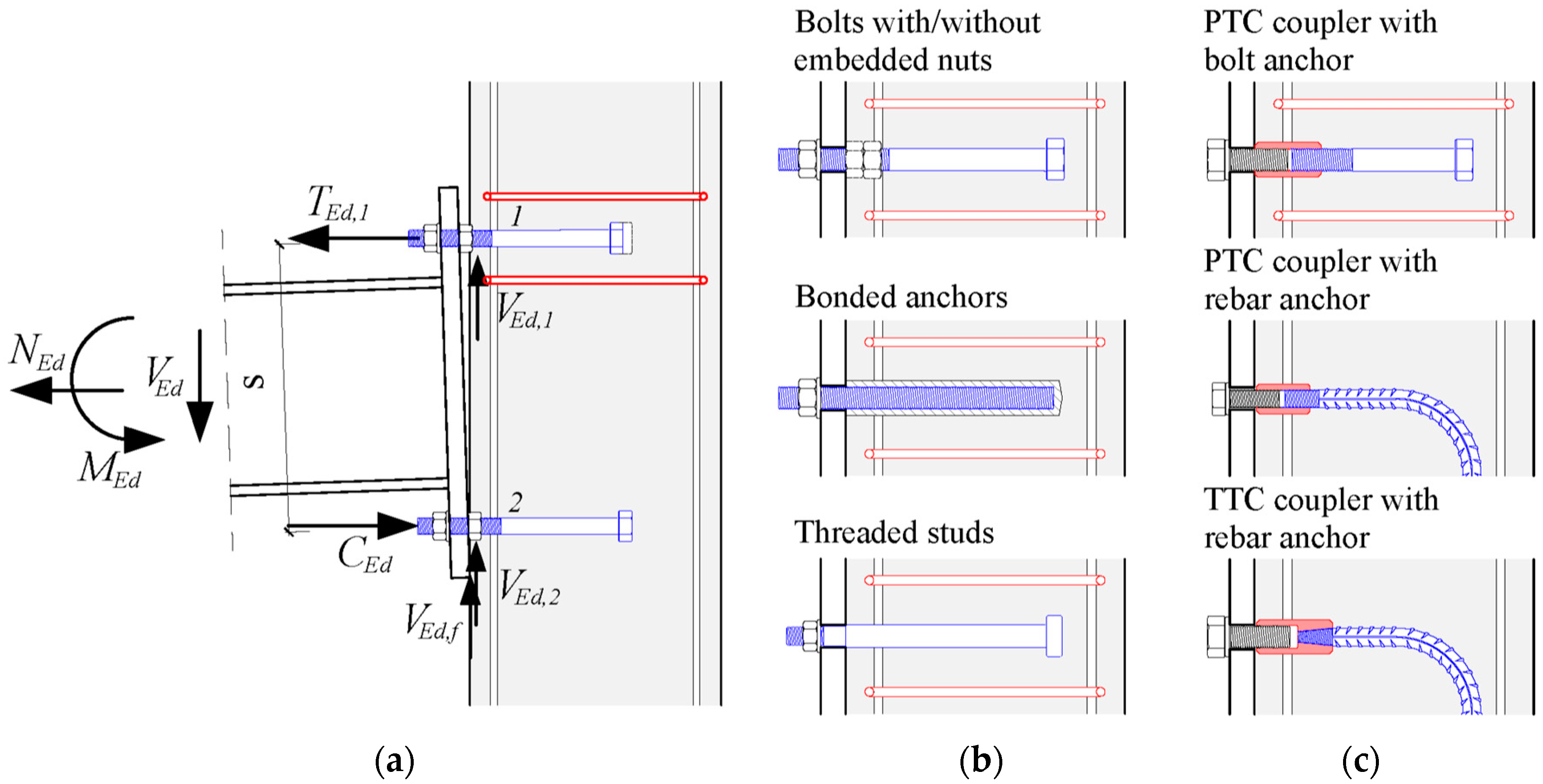
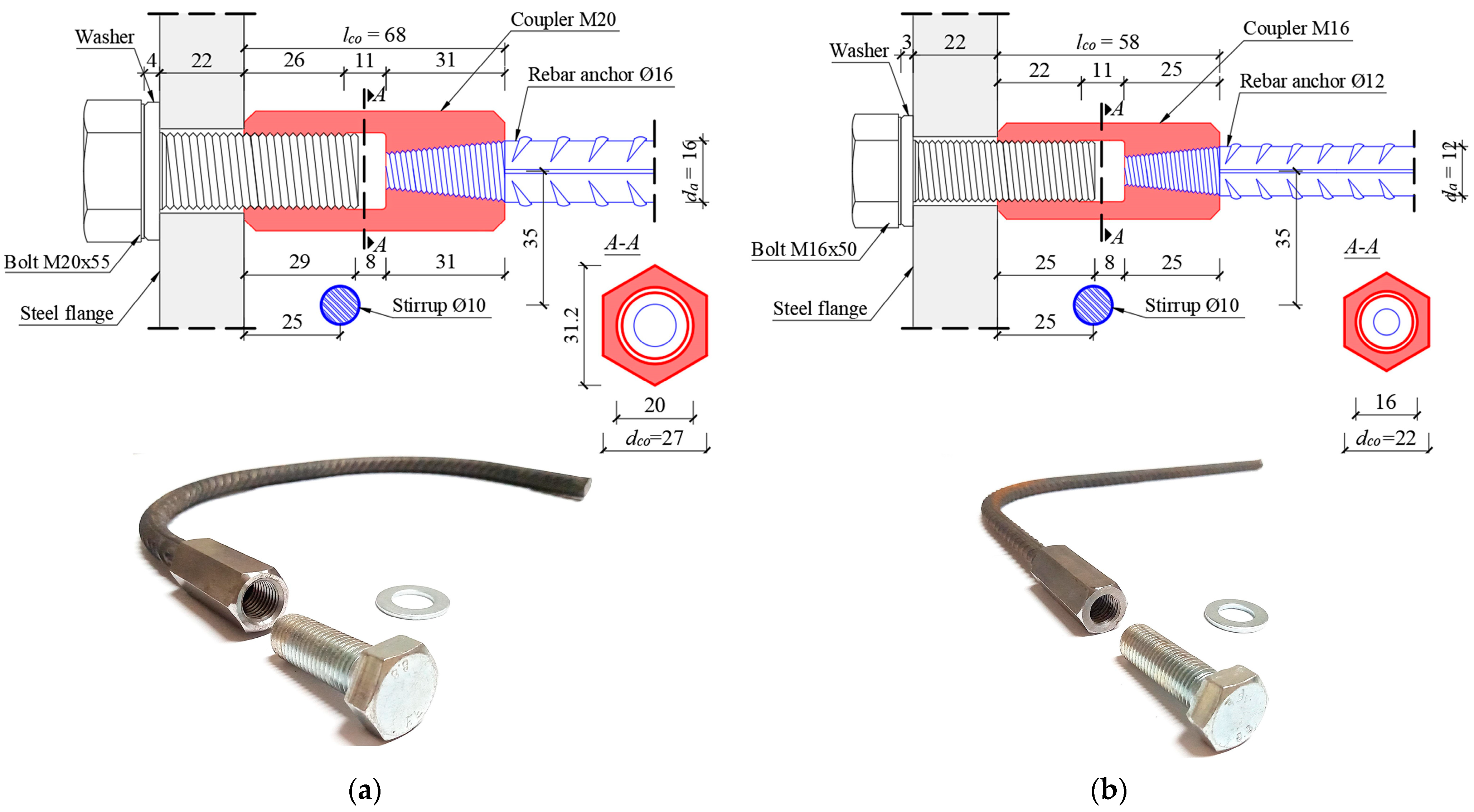
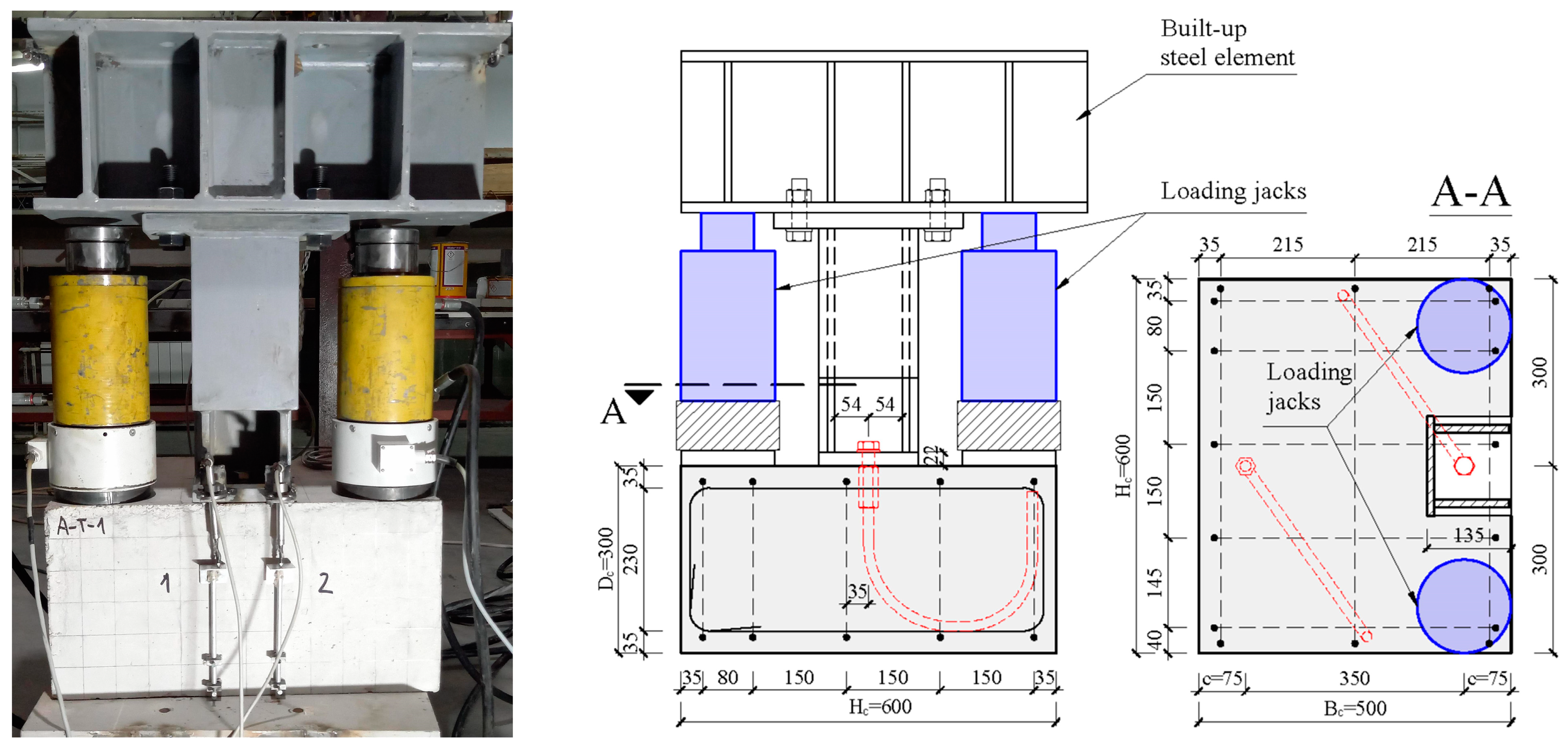
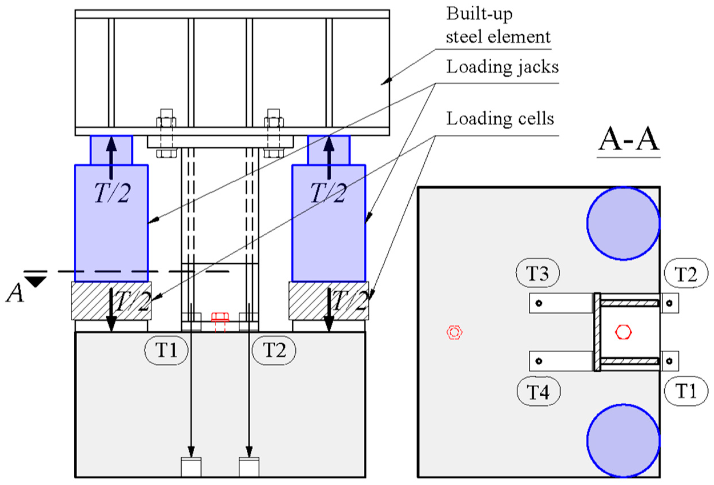
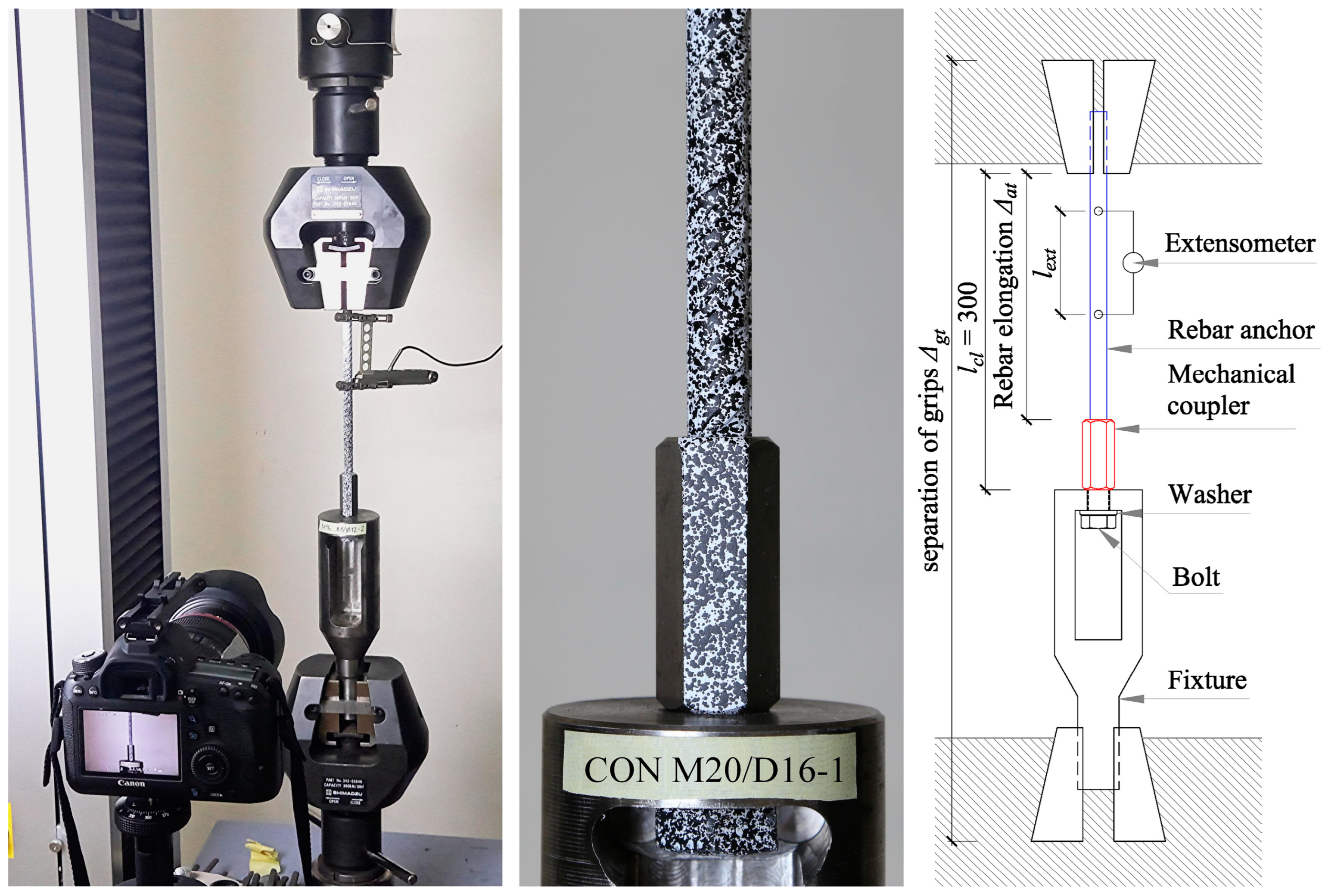
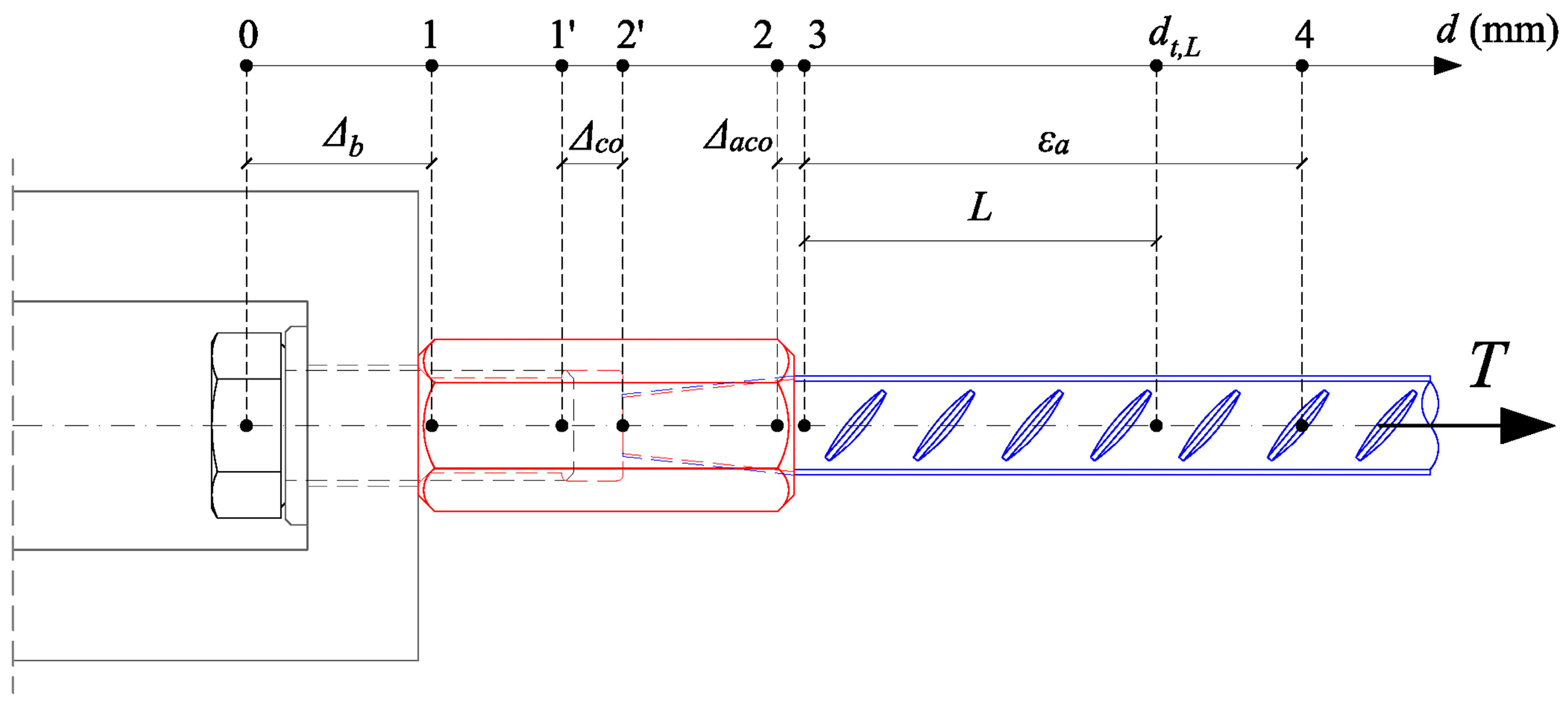
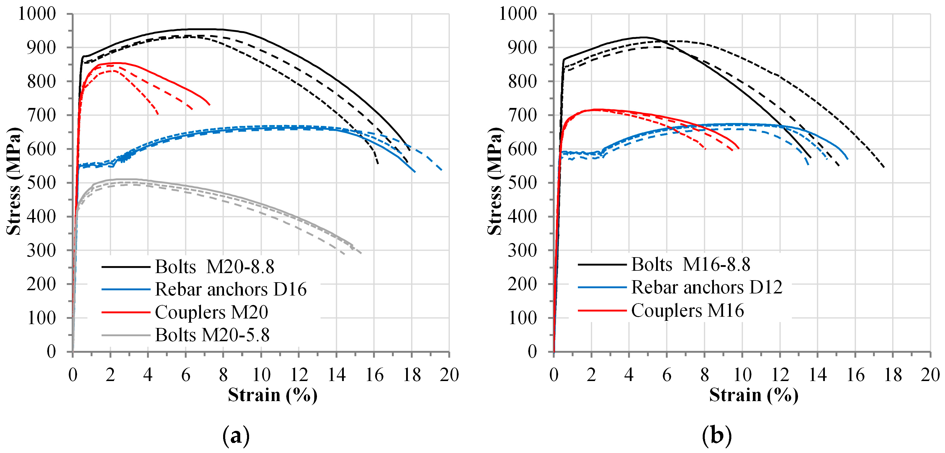
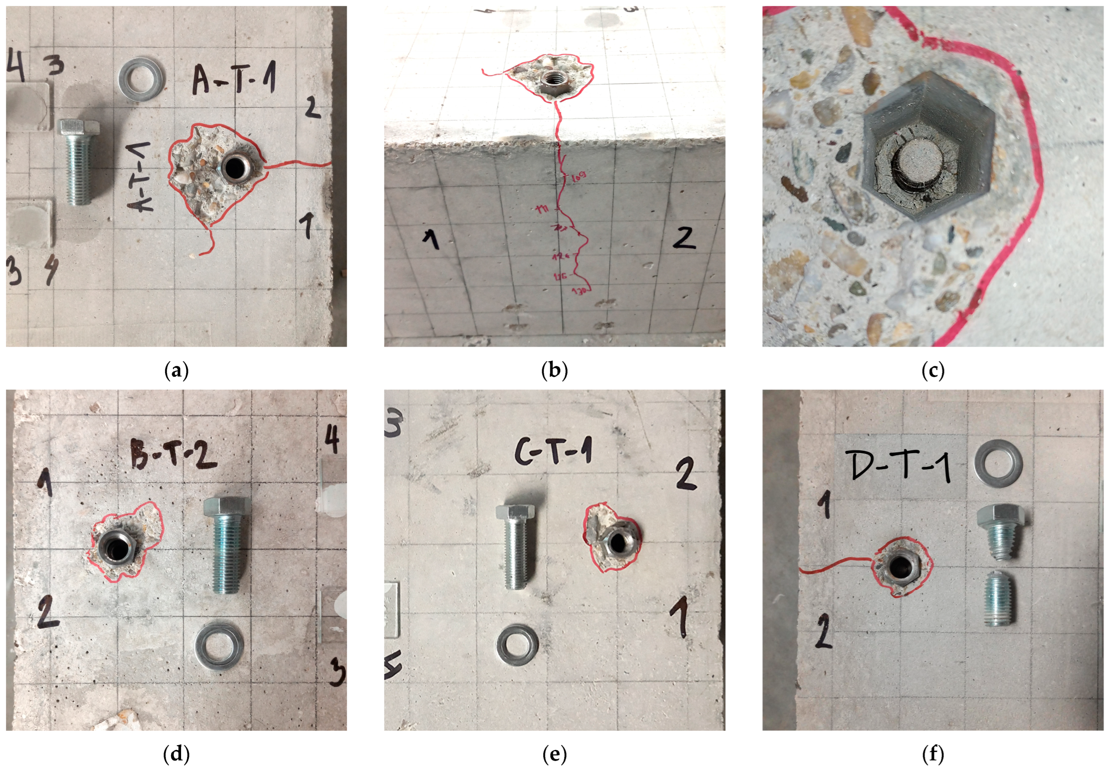
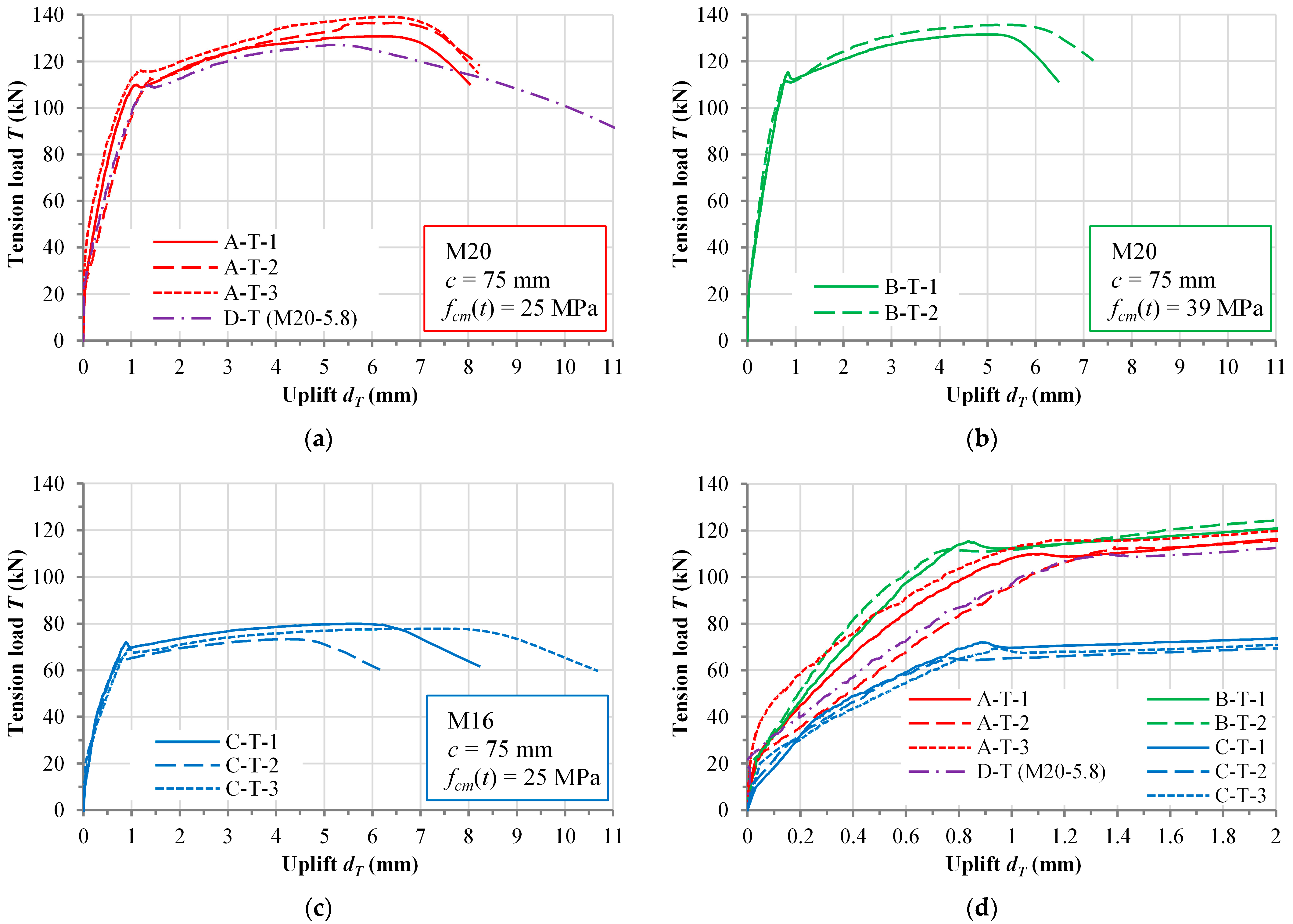
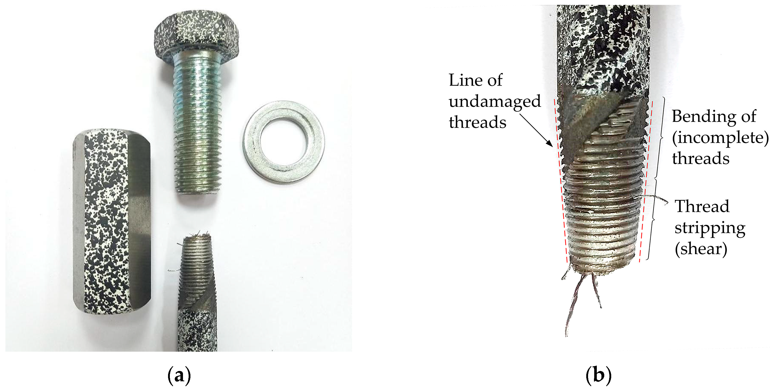
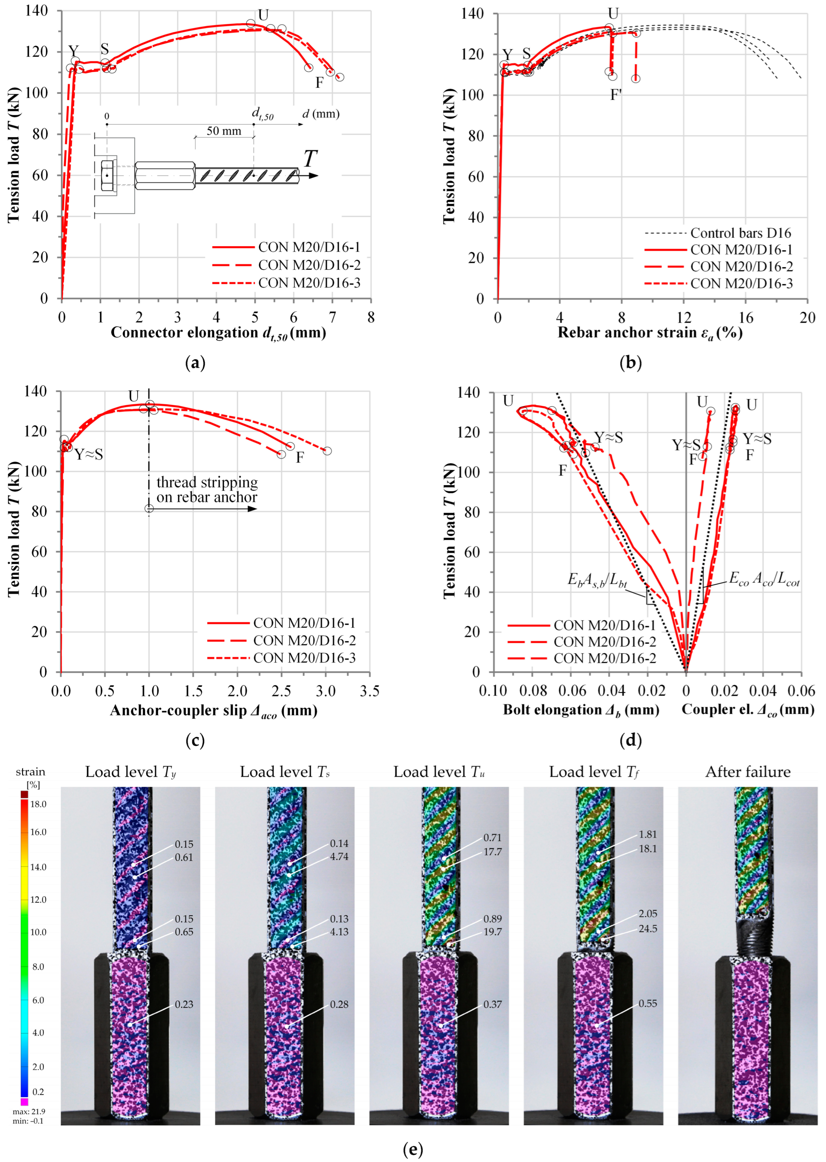
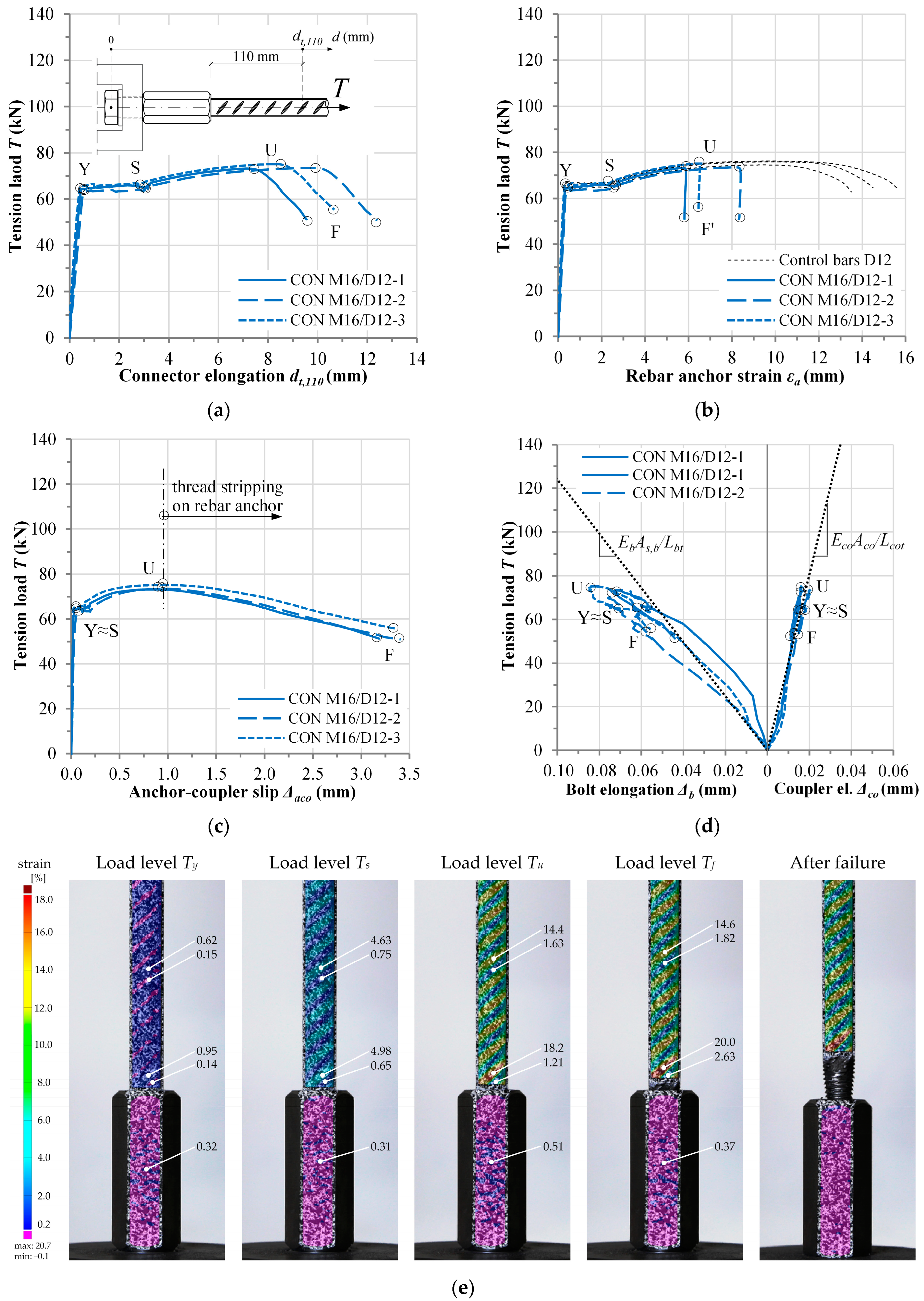
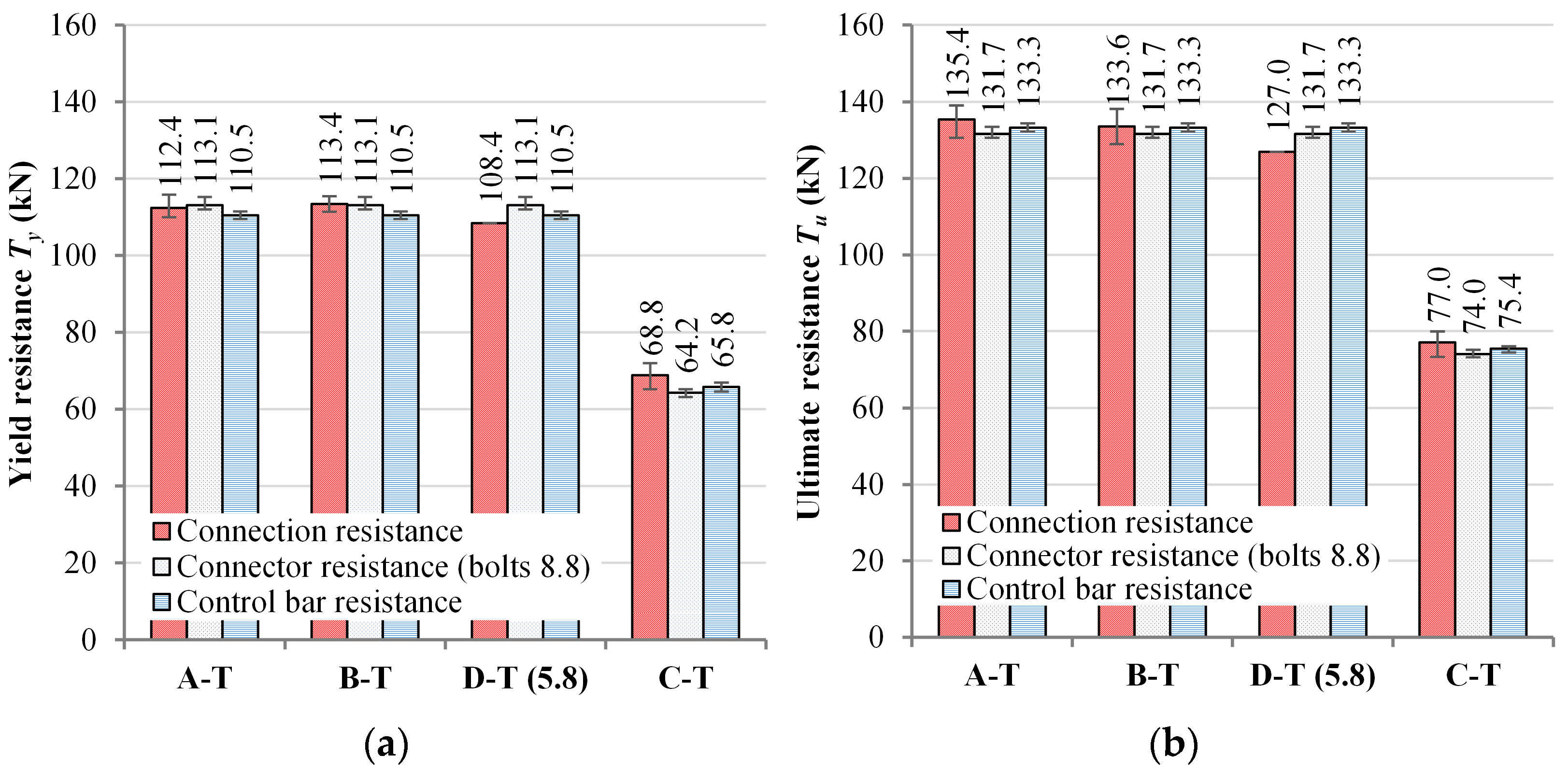
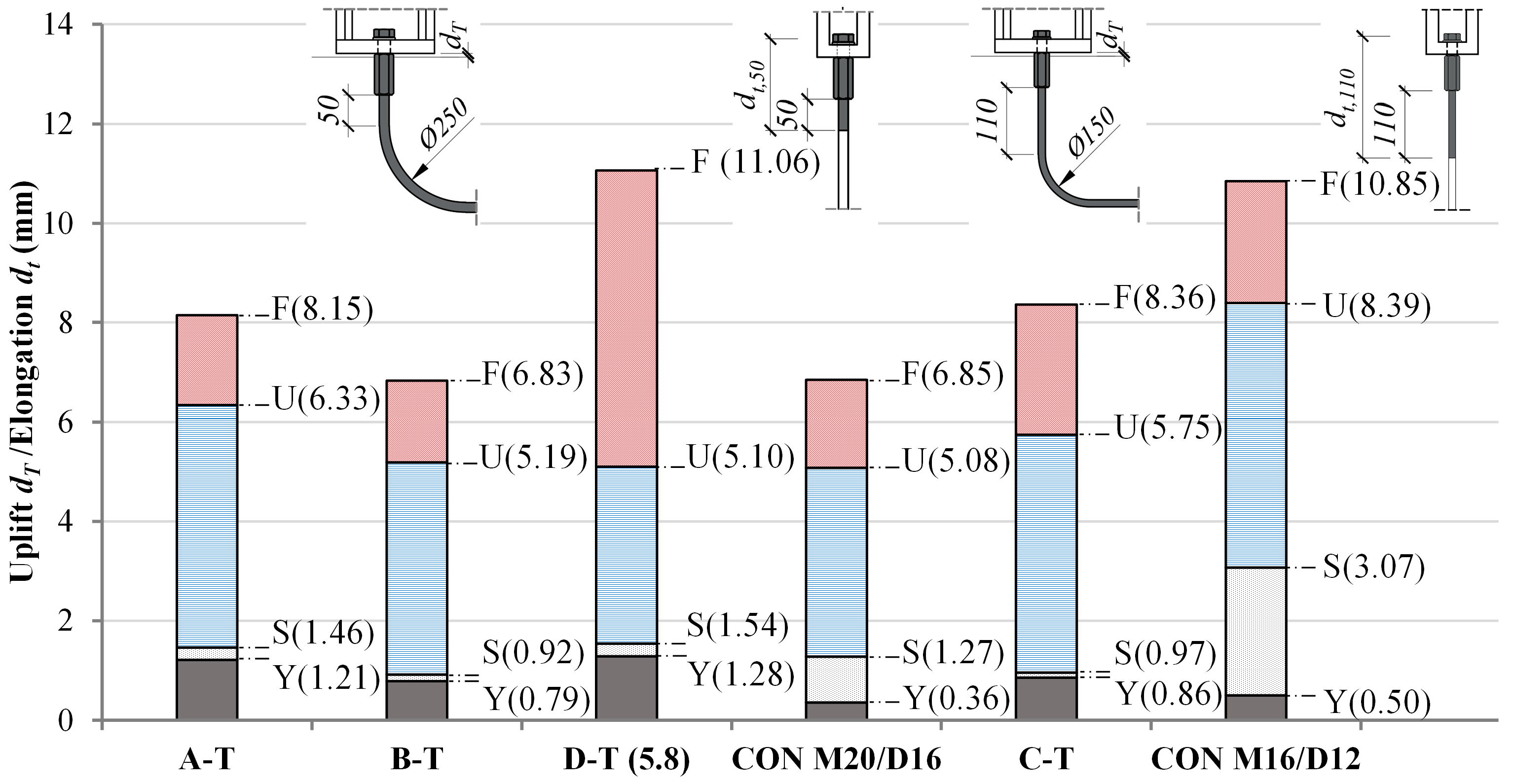
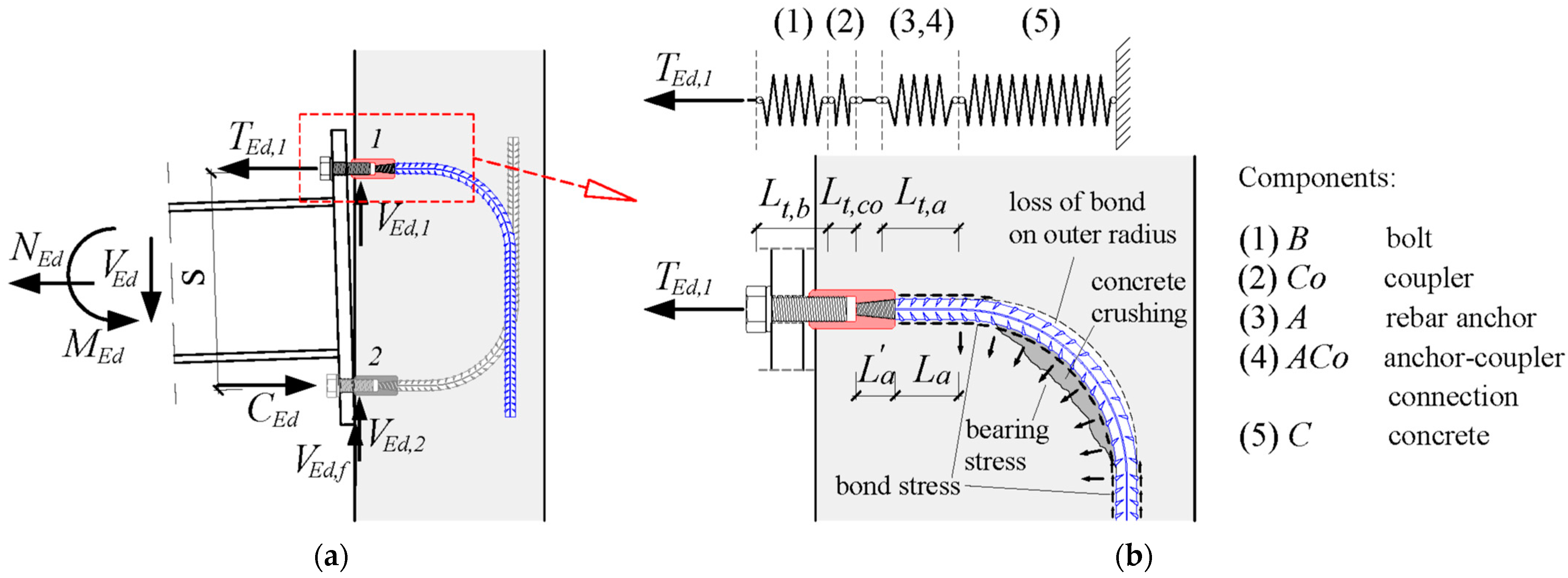
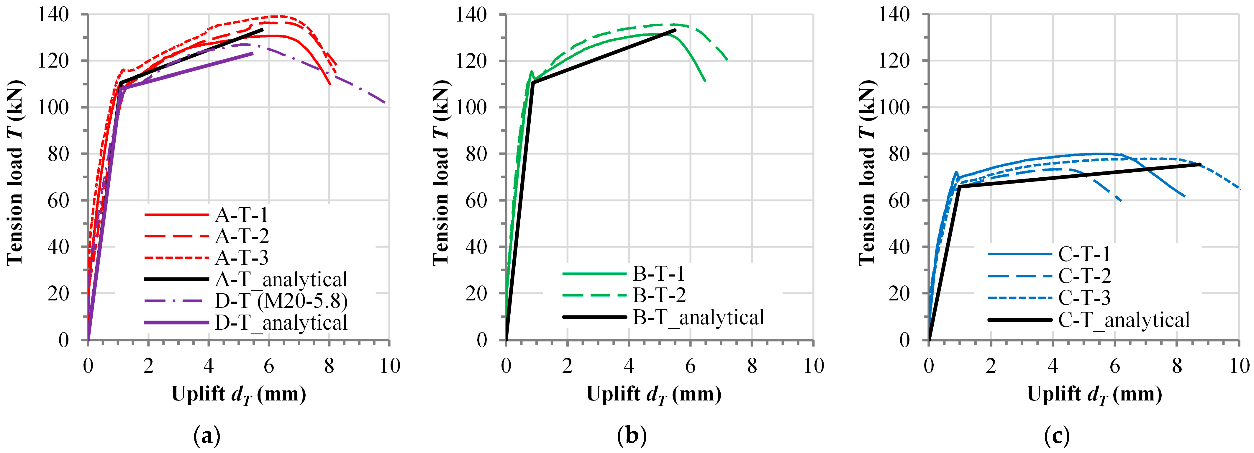
Disclaimer/Publisher’s Note: The statements, opinions and data contained in all publications are solely those of the individual author(s) and contributor(s) and not of MDPI and/or the editor(s). MDPI and/or the editor(s) disclaim responsibility for any injury to people or property resulting from any ideas, methods, instructions or products referred to in the content. |
© 2025 by the authors. Licensee MDPI, Basel, Switzerland. This article is an open access article distributed under the terms and conditions of the Creative Commons Attribution (CC BY) license (https://creativecommons.org/licenses/by/4.0/).