
Study on the Bending Performance of Connection Joints in a New Type of Modular Steel Structure Emergency Repair Pier

Abstract
1. Introduction
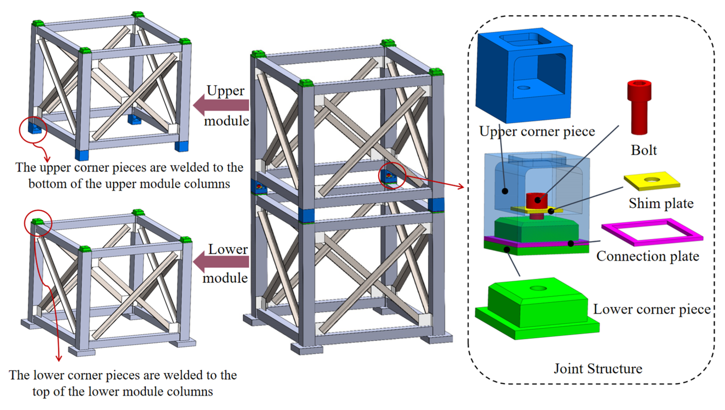
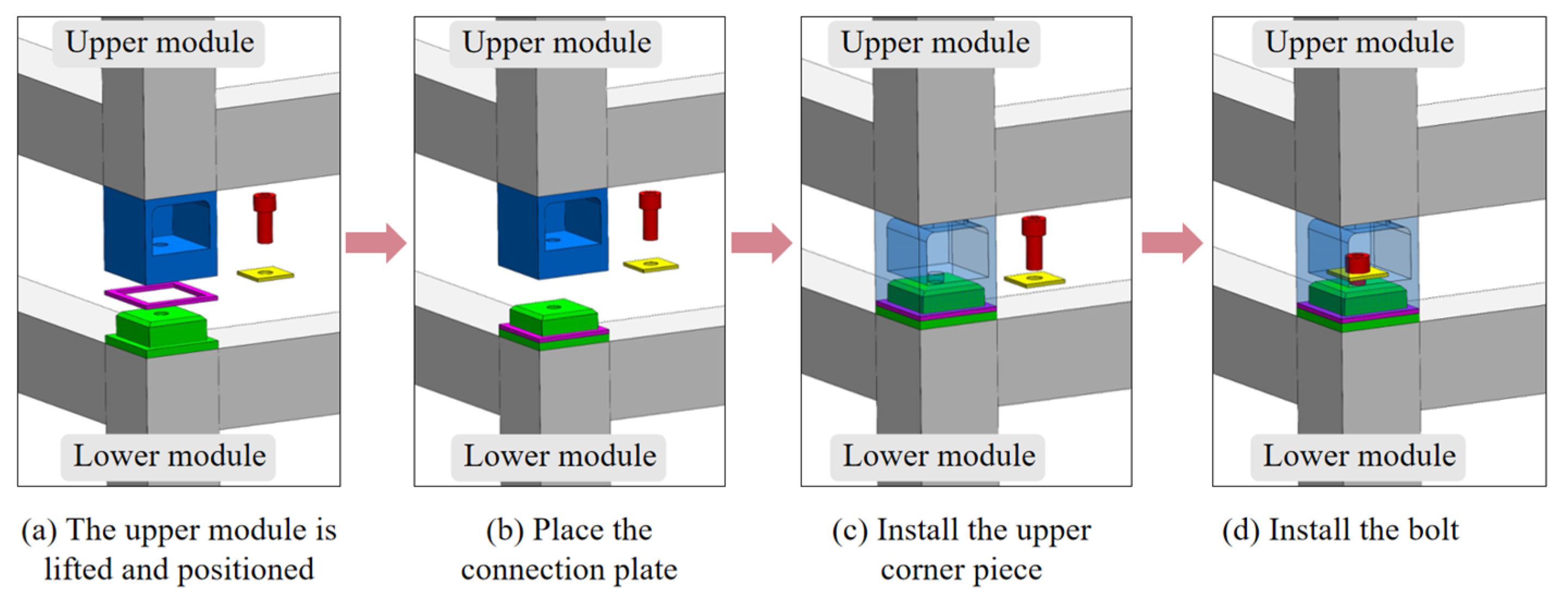
2. Joint Structure
3. Model Establishment
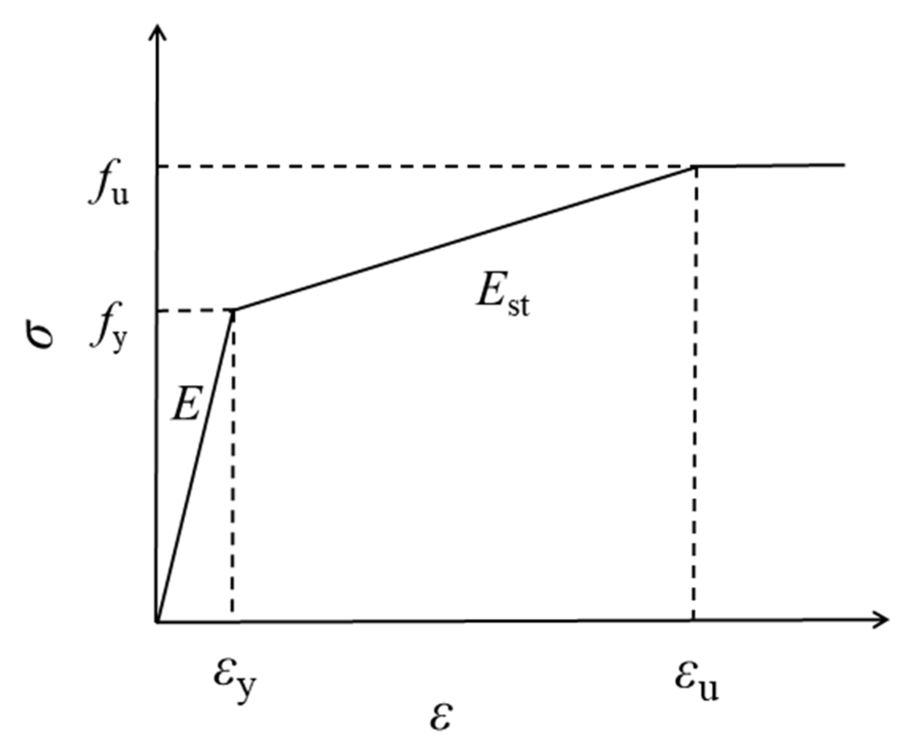
3.1. Constitutive Relationship of Steel
3.2. The Component Dimensions and Finite Element Simulation Parameters
3.3. Model Setup
3.3.1. Mesh Division
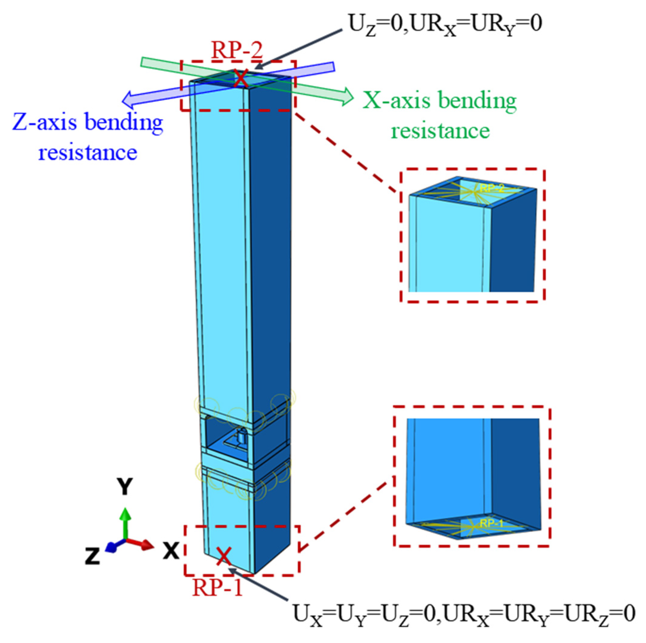
3.3.2. Interactions and Boundary Conditions
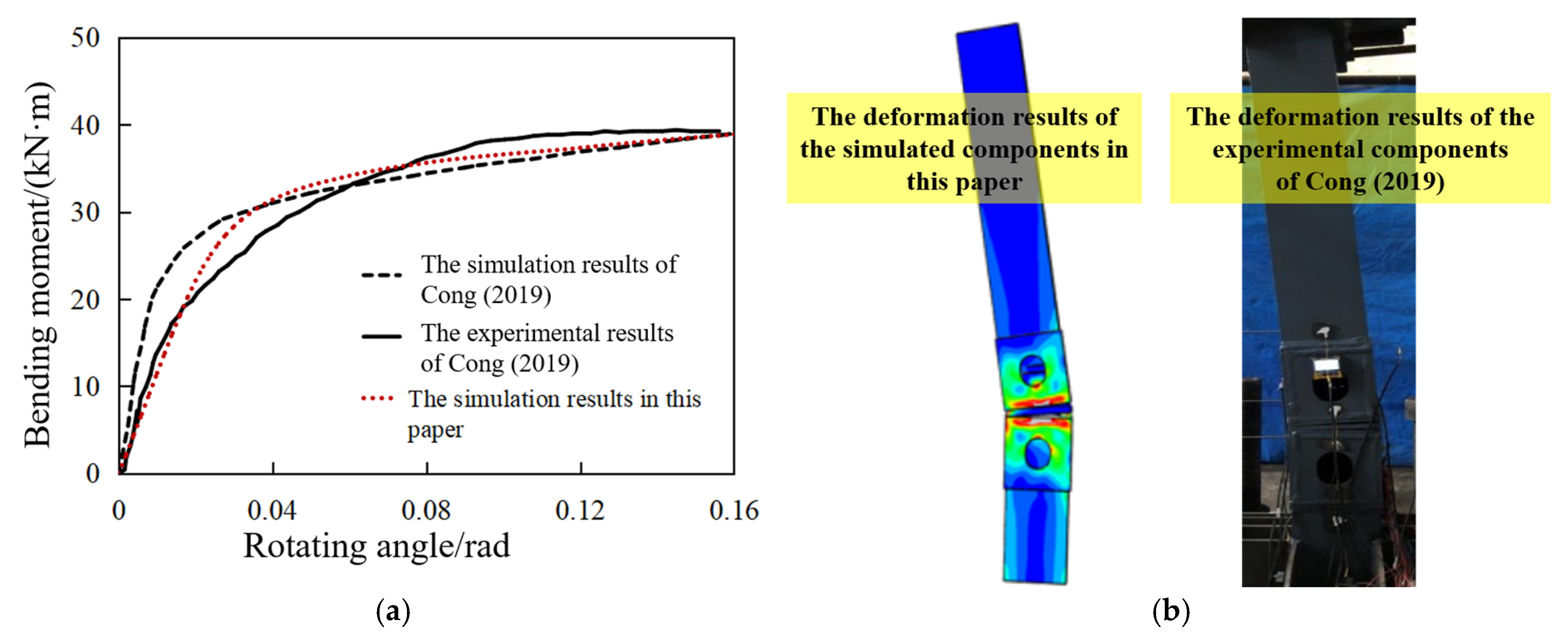
3.4. Feasibility Verification of Finite Element Modeling and Analysis Methods
4. Parameter Analysis
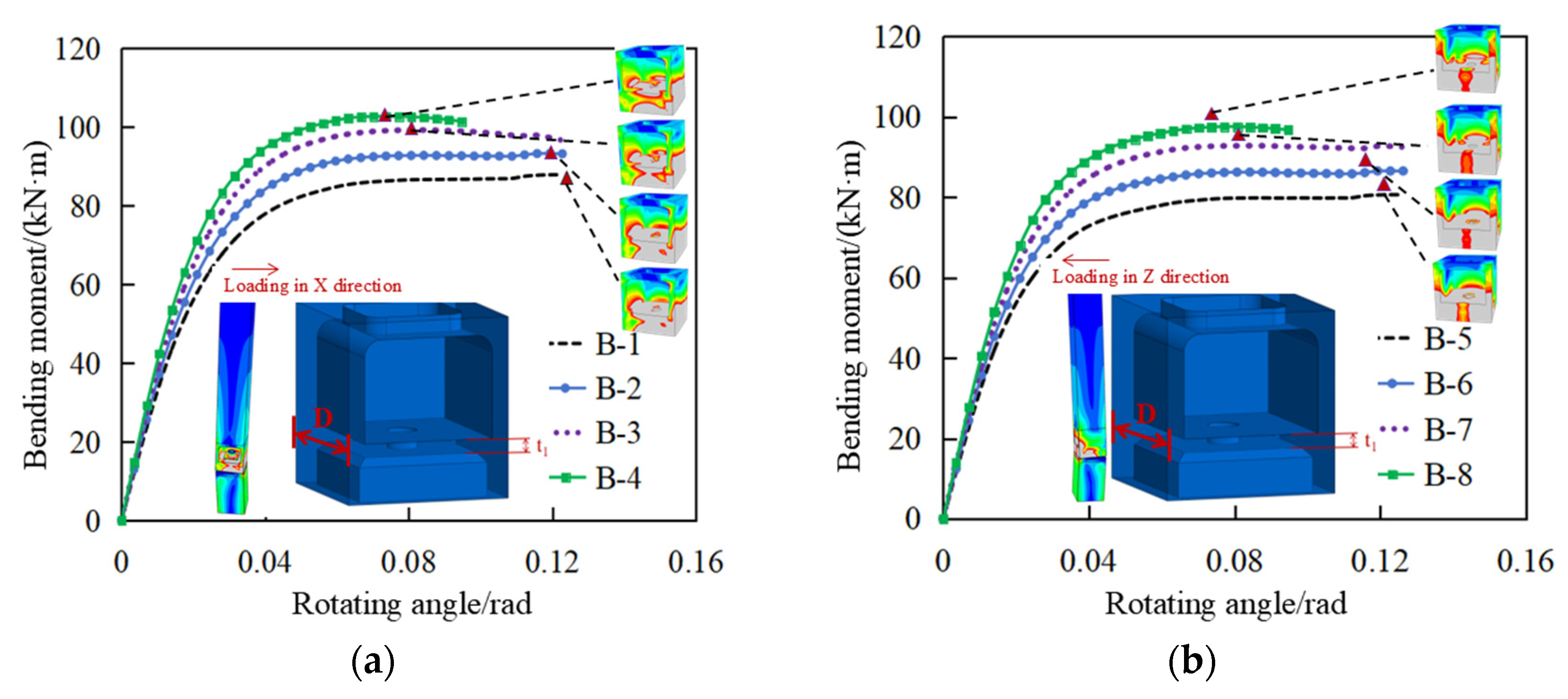
4.1. The Influence of the Width-to-Thickness Ratio of the Upper Corner Piece Base Plate
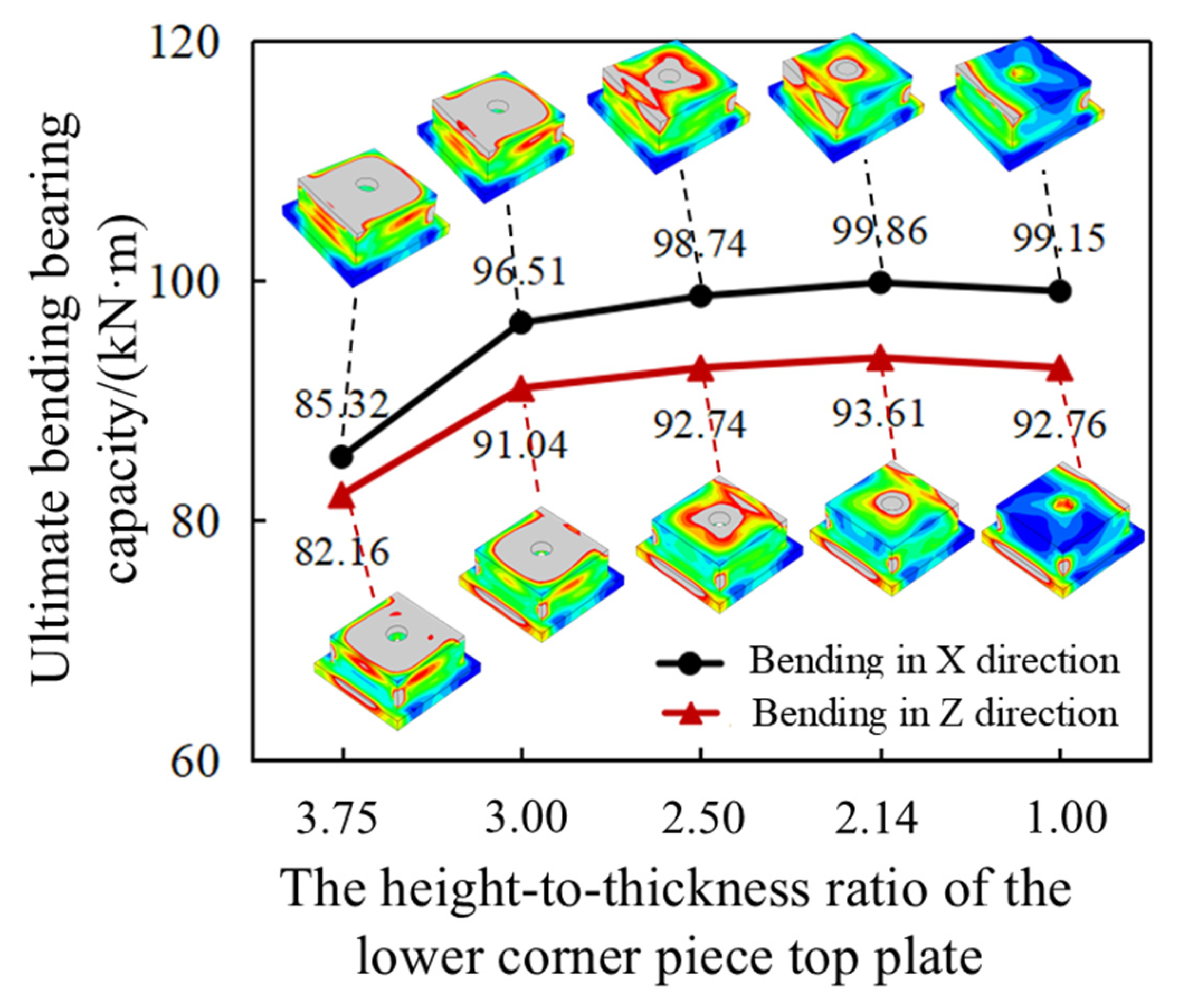
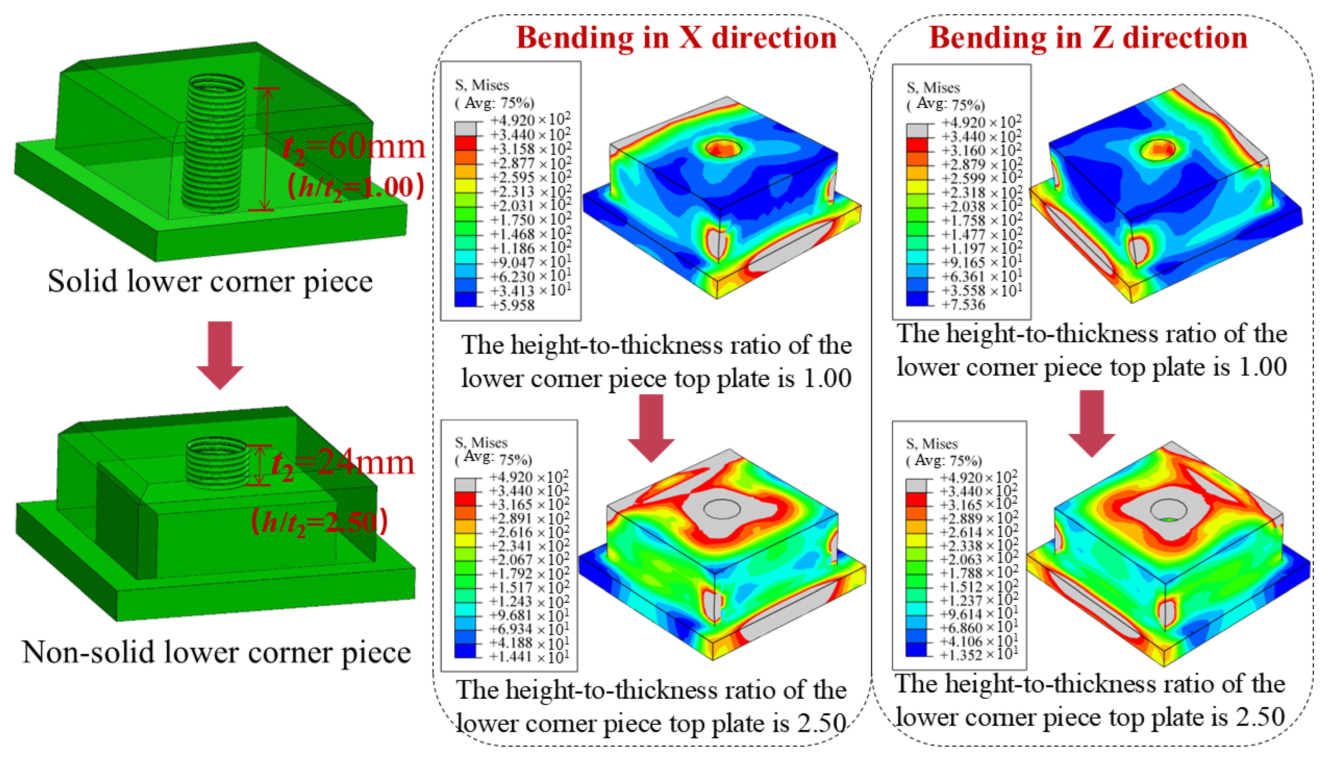
4.2. The Influence of the Height-to-Thickness Ratio of the Lower Corner Piece Top Plate
4.3. The Influence of the Height of the Protrusion of the Lower Corner Piece
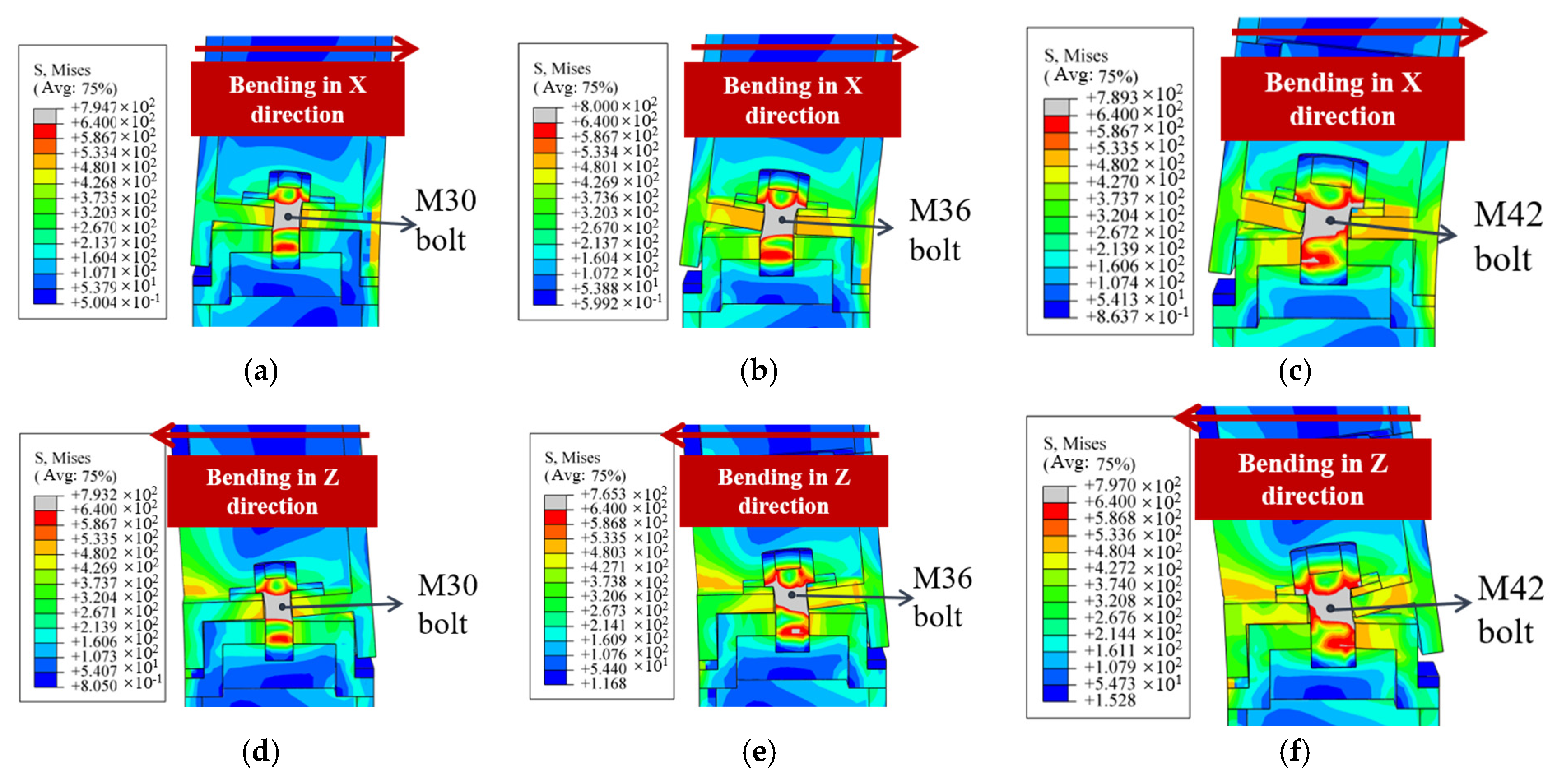
4.4. The Influence of Bolt Diameter
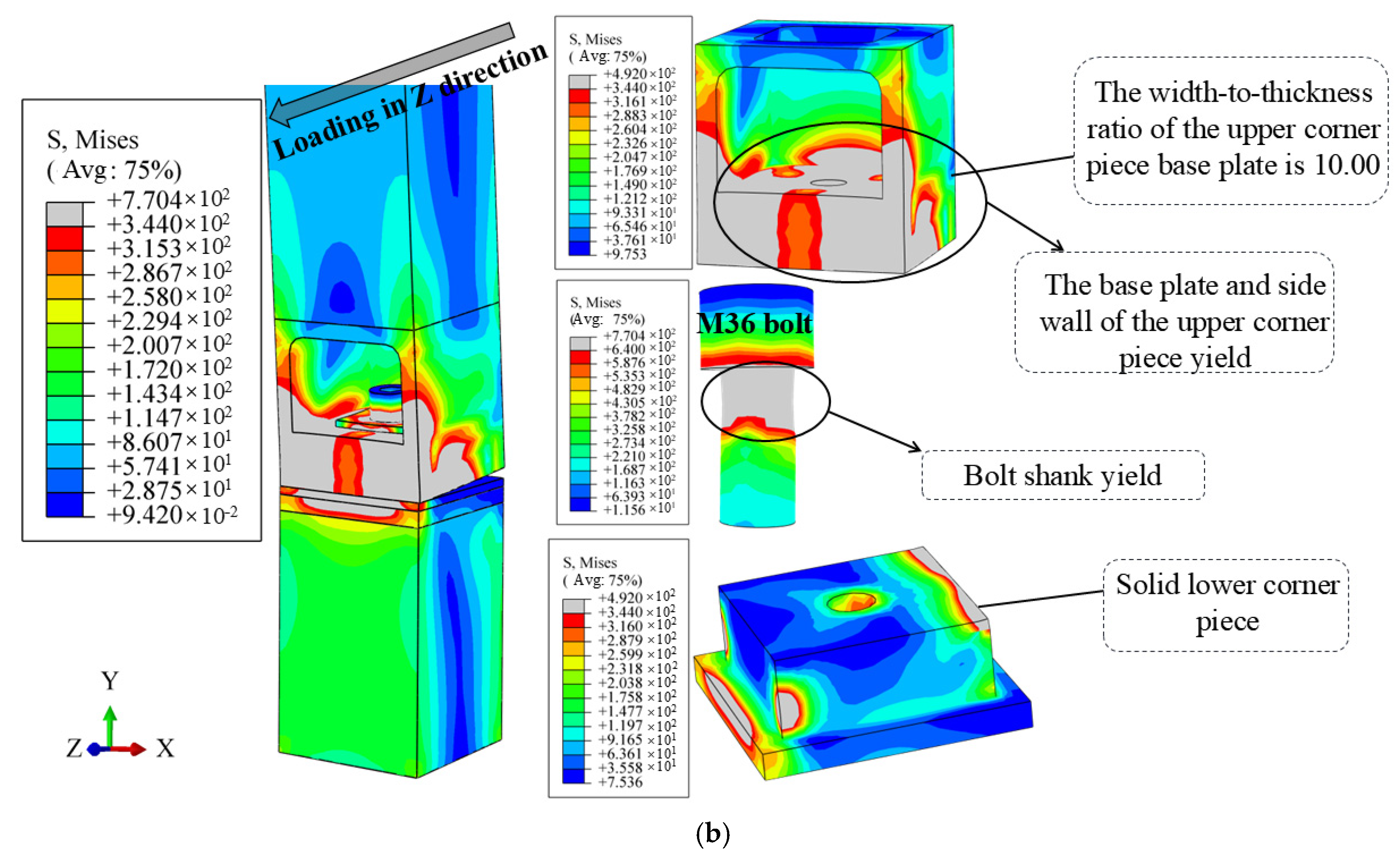
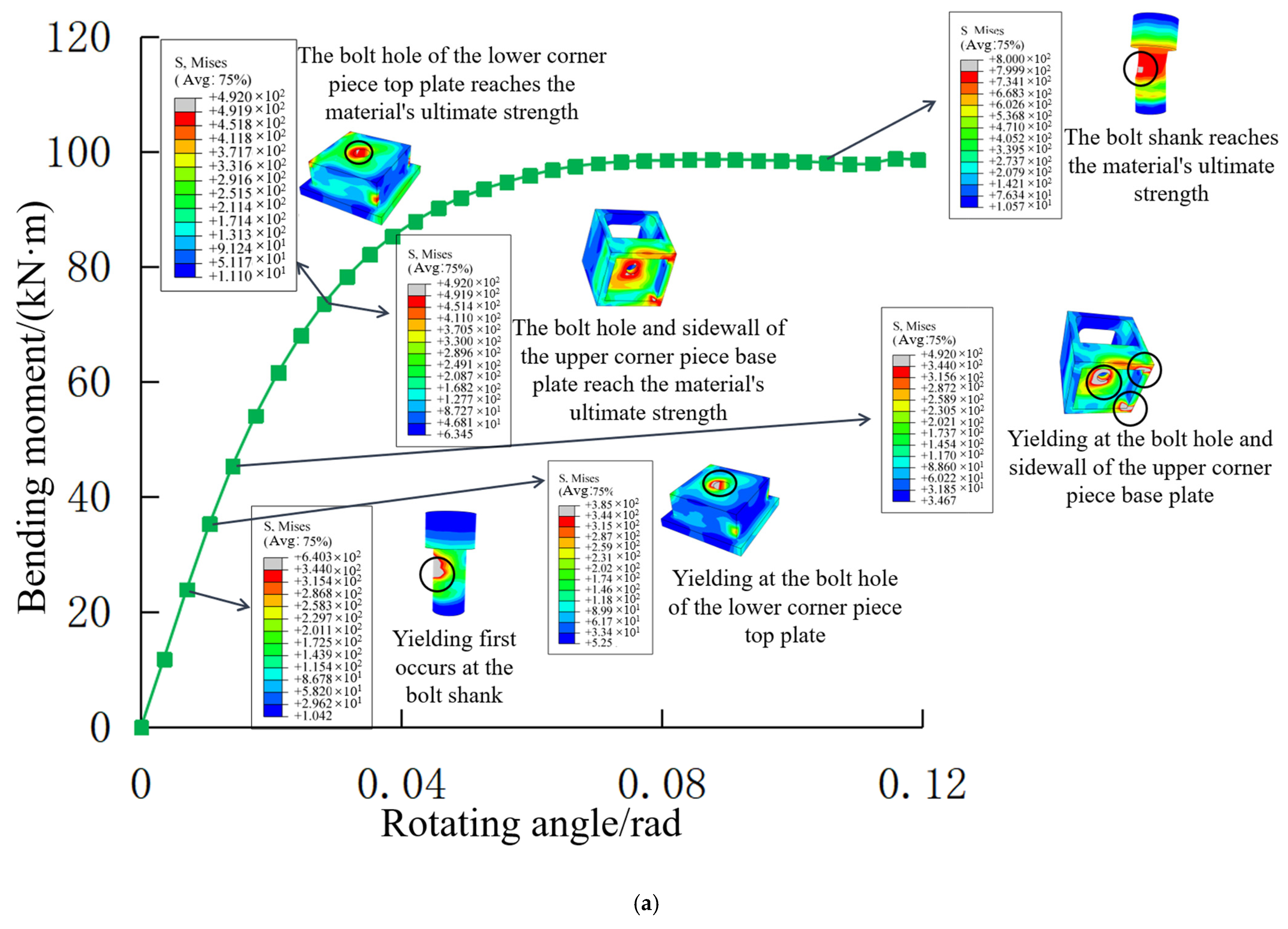
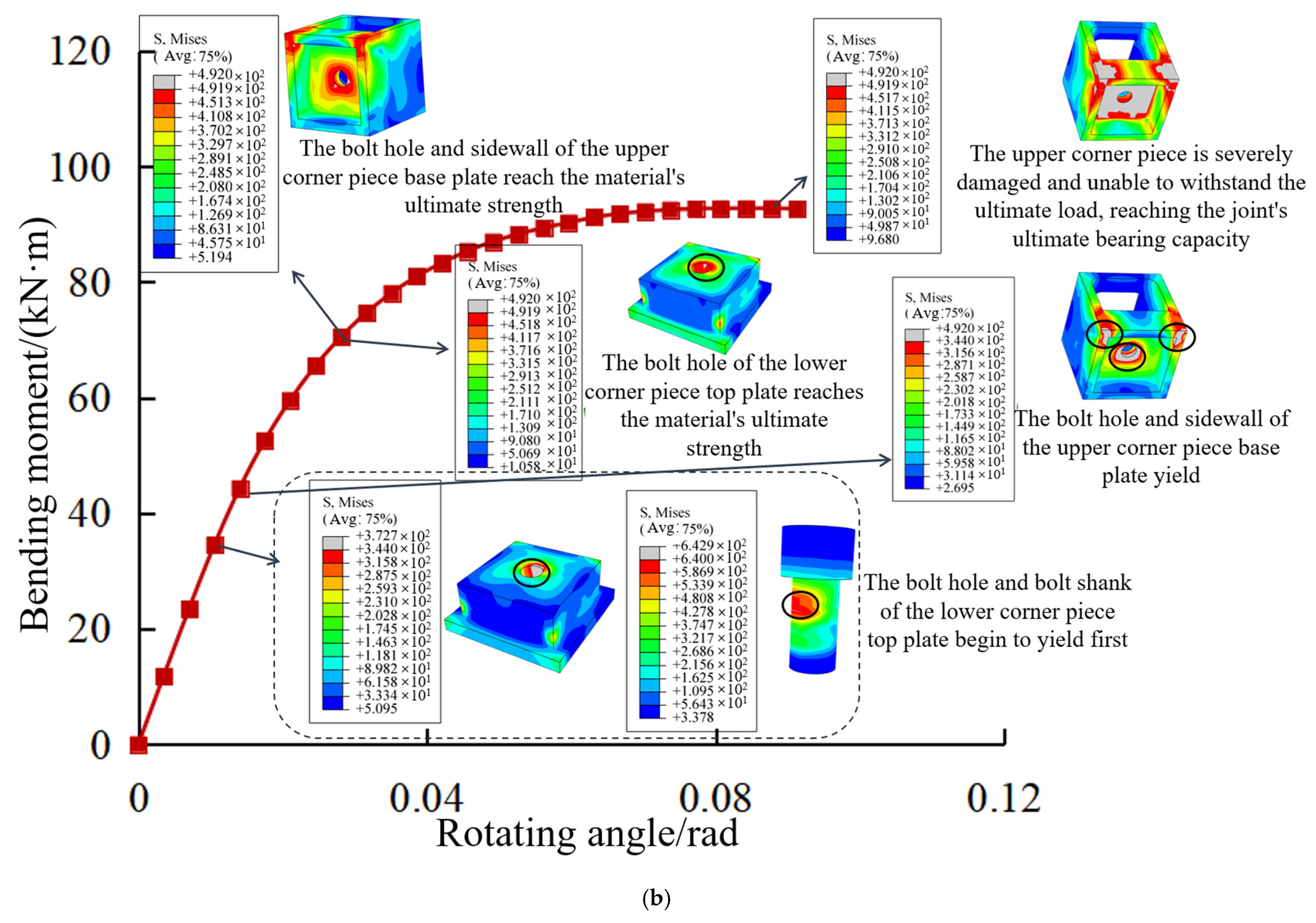
4.5. Development of Bending Stress in the Joint
4.6. The Influence of Axial Compression
5. Joint Property Determination
6. Calculation of the Initial Bending Stiffness of the Joint
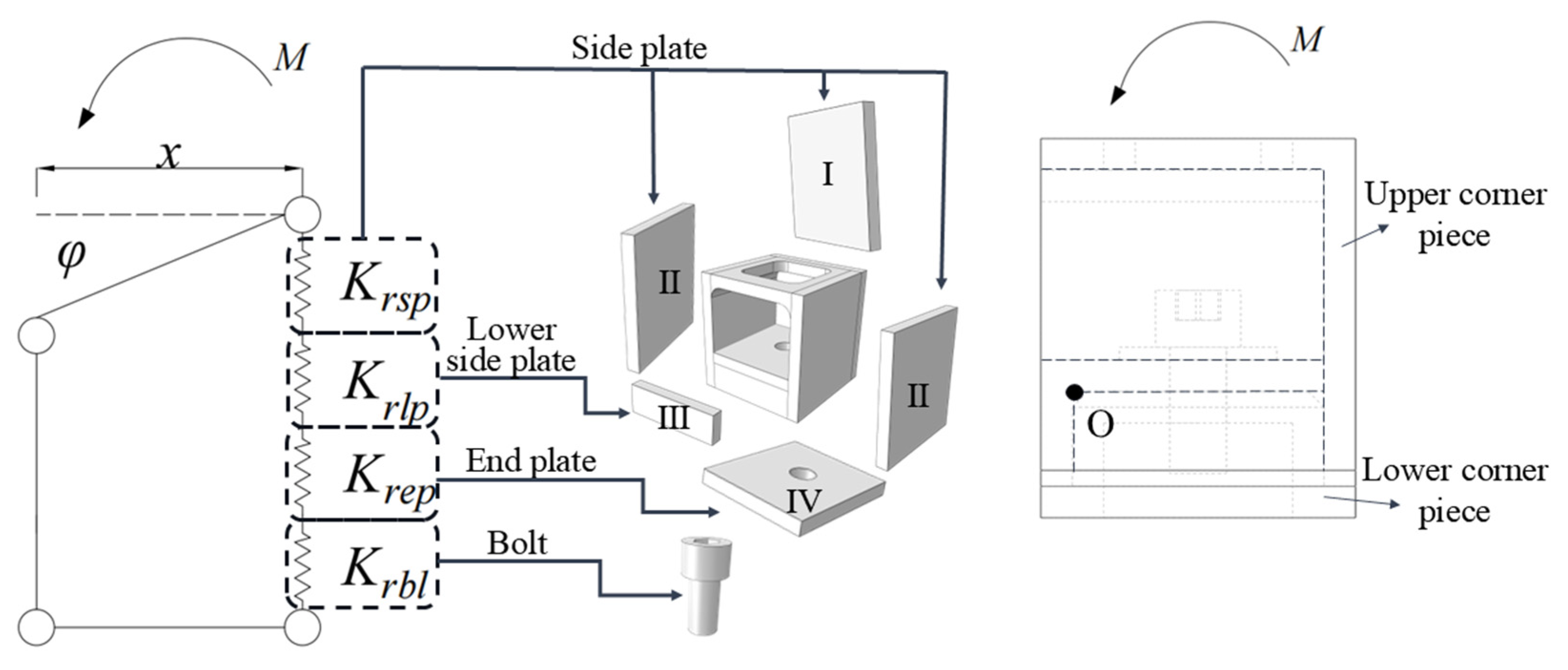
- The rotational center of all equivalent springs is assumed to be point O.
- Based on the position of the opening, the upper corner piece of the joint is divided into the side plates (Plate I and Plate II), the lower side plate (Plate III), and the end plate (Plate IV).
- Since the deformation of the lower corner piece is relatively small during the bending process of the joint, the influence of the lower corner piece on the overall bending stiffness of the joint is neglected. The overall bending stiffness of the joint is obtained by the combination of the stiffness of the upper corner piece and the bolt.
- (1)
- Calculation of the stiffness of the side plate (Plate I and Plate II) of the upper corner piece.
- (2)
- The compressive stiffness of the lower side plate (plate III) of the upper corner piece is calculated as shown in Equation (9).
- (3)
- The bending stiffness of the end plate (plate IV) of the upper corner piece is calculated as shown in Equation (10).
- (4)
- The tensile stiffness of the bolt is calculated as shown in Equation (11).
7. Conclusions
- A new type of modular steel structure emergency repair pier joint is proposed, aiming to achieve rapid assembly and connection between modular units, thereby improving the bridge repair speed.
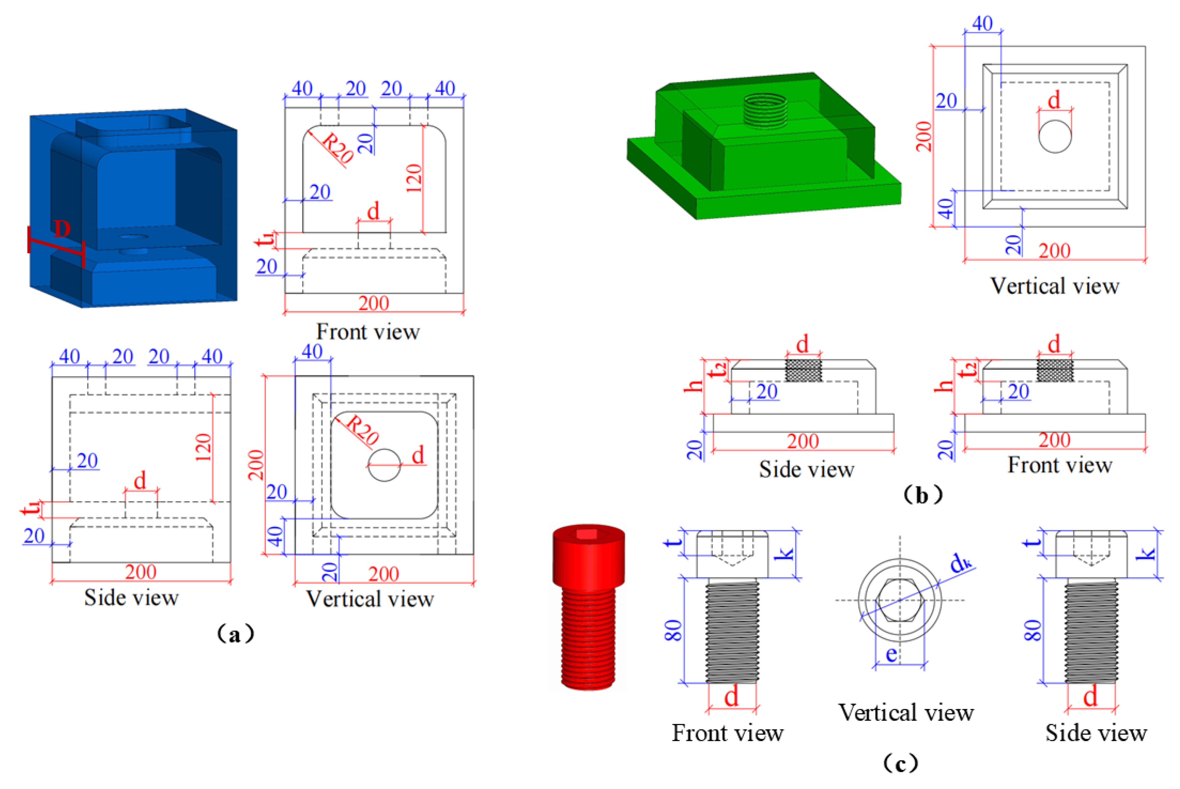
- The width-to-thickness ratio of the upper corner piece base plate D/t1 (where D is the width of the upper corner piece base plate and t1 is the thickness of the upper corner plate), the height-to-thickness ratio of the lower corner piece top plate h/t2 (where h is the height of the protrusion of the lower corner piece and t2 is the thickness of the lower corner piece top plate), the height of the protrusion of the lower corner piece (h), and the bolt diameter (d) are selected as parameters to study the bending performance of the new type of modular steel structure emergency repair pier joint. The recommended values are as follows: t1 is 20 mm, D/t1 is 10.00; t2 is 24 mm, h/t2 is 2.50; h is greater than or equal to 30 mm, and d is either 36 mm or 42 mm.
- The bending performance of the joint under axial compression ratios of 0.1, 0.2, and 0.3 is studied separately. The results show that as the axial compression ratio increases, the yield rotation angle and ultimate rotation angle of the joint decrease, and the rate of decline in the bearing capacity increases after the joint reaches its ultimate load-bearing capacity. Under the action of the X-direction horizontal lateral displacement load, the initial bending stiffness and bending capacity of the joint increase with the axial compression ratio. Under the action of Z-direction horizontal lateral displacement load, the initial bending stiffness of the joint increases with the axial compression ratio, while its bending bearing capacity does not change significantly.
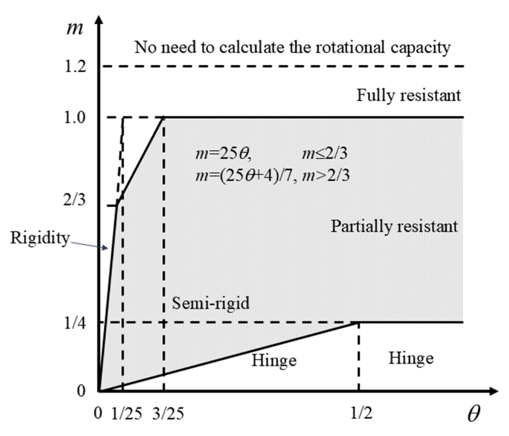
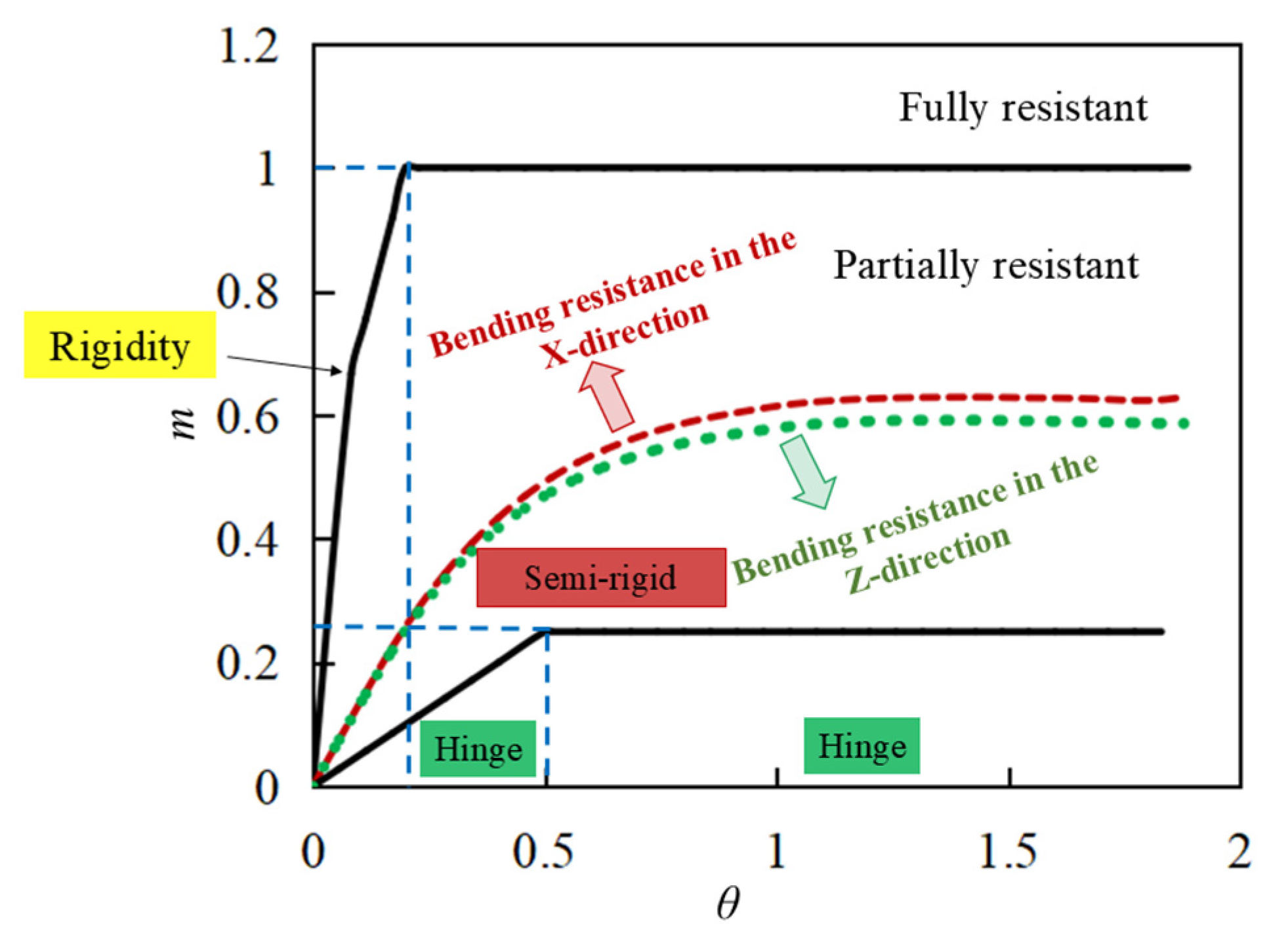
- The new type of modular steel structure emergency repair pier joint is classified as a partially resistant joint from the perspective of bearing capacity and as a semi-rigid joint from the perspective of stiffness.
- A simplified calculation model for the joint was proposed based on the component method. The accuracy of the theoretical calculation model in this study is within 20%, which provides certain guidance for structural design and engineering applications.
8. Future Work
- This paper only analyzes the bending performance of the joint. Future research will continue to focus on the tensile performance, compressive performance, shear performance, and the overall structure of the repair pier.
- This paper investigates the bending performance of the joint through finite element numerical simulation, and future studies will continue with experimental research for further investigation.
Author Contributions
Funding
Data Availability Statement
Conflicts of Interest
References
- Luca, C.; Fabio, B.; Frangopol, M.D. Resilience of aging structures and infrastructure systems with emphasis on seismic resilience of bridges and road networks: Review. Resilient Cities Struct. 2022, 1, 23–41. [Google Scholar]
- Angel, M.M.; Maria, N.; Oswaldo, M. Estimating bridge criticality due to extreme traffic loads in highway networks. Eng. Struct. 2024, 300, 117172. [Google Scholar]
- Chen, S.; Zhang, Y.; Zhang, P. An exploration into the emergency support for concrete bridges of high-speed railways. Traffic Eng. Technol. Natl. Def. 2015, 13, 4–6. (In Chinese) [Google Scholar] [CrossRef]
- Tang, K.A.; Eng, P.; Eng, C.; Asce, F. Lifelines Performance of the Mw 8.8 off Shore Biobío, Chile Earthquake. Procedia Eng. 2011, 14, 922–930. [Google Scholar] [CrossRef]
- Urlainis, A.; Ornai, D.; Levy, R.; Vilnay, O.; Shohet, I.M. Loss and damage assessment in critical infrastructures due to extreme events. Saf. Sci. 2022, 147, 105587. [Google Scholar] [CrossRef]
- Pregnolato, M. Bridge safety is not for granted—A novel approach to bridge management. Eng. Struct. 2019, 196, 109193. [Google Scholar] [CrossRef]
- Chen, S.; Liu, Z.; Zhi, M. Current situation and thinking on rush-repair equipment for bridge piers in China. Railw. Tech. Stand. (Chin. Engl.) 2022, 4, 14–19. (In Chinese) [Google Scholar]
- Chu, Y.; Xia, H.; Zhang, H.; Xiao, Y. Dynamic response analysis of the new layered assembled lattice piers under lateral impact. Structures 2024, 70, 107801. [Google Scholar] [CrossRef]
- Liu, Z.; Chen, S.; Zhi, M. Rapid design method for composite emergency steel piers with thin-walled steel tube framework and discussion on “temporary-permanent” transition. Structures 2024, 69, 107350. [Google Scholar] [CrossRef]
- Zhang, Q. Research on emergency repair technology of expressway bridges under disaster conditions. Eng. Technol. Res. 2023, 8, 61–63. (In Chinese) [Google Scholar] [CrossRef]
- Zhang, Z. My reflection on the current situation of the emergency support capability of rush-repair equipment of railway bridges. Traffic Eng. Technol. Natl. Def. 2020, 18, 30–33. (In Chinese) [Google Scholar] [CrossRef]
- Yang, C.; Xu, B.; Xia, J.; Chang, H.; Chen, X.; Ma, R. Mechanical Behaviors of Inter-Module Connections and Assembled Joints in Modular Steel Buildings: A Comprehensive Review. Buildings 2023, 13, 1727. [Google Scholar] [CrossRef]
- Chen, Z.; Liu, Y.; Zhong, X.; Liu, J. Rotational stiffness of inter-module connection in mid-rise modular steel buildings. Eng. Struct. 2019, 196, 109273. [Google Scholar] [CrossRef]
- Zhu, X.; Yan, J.; Wu, J. Latest progress of intermodule connections of steel modular buildings. Build. Struct. 2022, 52, 1532–1538. (In Chinese) [Google Scholar]
- Isaac, S.; Bock, T.; Stoliar, Y. A methodology for the optimal modularization of building design. Autom. Constr. 2016, 65, 116–124. [Google Scholar] [CrossRef]
- Ministry of Housing and Urban-Rural Development of the People’s Republic of China. Technical Guide for Prefabricated Steel Construction Modules. 2022. Available online: https://www.wiskindsteelstructure.com/ministry-of-housing-and-urban-rural-development-issues-technical-guide-for-prefabricated-steel-structure-module-buildings_n78 (accessed on 9 June 2022). (In Chinese).
- Lacey, W.A.; Chen, W.; Hao, H.; Bi, K. Review of bolted inter-module connections in modular steel buildings. J. Build. Eng. 2019, 23, 207–219. [Google Scholar] [CrossRef]
- Ferdous, W.; Bai, Y.; Ngo, D.T.; Manalo, A.; Mendis, P. New advancements, challenges and opportunities of multi-storey modular buildings—A state-of-the-art review. Eng. Struct. 2019, 183, 883–893. [Google Scholar] [CrossRef]
- Chen, Y.; Sun, W.; Liu, X.; Liu, Y.; Liu, Y. Research progress of modular building and modular joints. In Proceedings of the 23rd National Symposium on Modern Structural Engineering, Lanzhou, China, 21 July 2023; Tianjin Institute of Steel Structures, Tianjin University: Tianjin, China; College of Urban and Rural Construction, Hebei Agricultural University: Baoding, China; School of Architectural Engineering, Tianjin University: Tianjin, China, 2023; p. 6. (In Chinese). [Google Scholar]
- Zhai, S.Y.; Lyu, Y.F.; Cao, K.; Li, G.Q.; Wang, W.Y.; Chen, C. Experimental-numerical investigation and design of bolted-cover plate connections under bending for modular steel buildings. J. Build. Eng. 2023, 75, 107057. [Google Scholar] [CrossRef]
- Sha, L.; Tu, F.; Kang, C.; Wu, Z. Study on seismic performance of cantilever beam-column connection with Z-shaped full-bolted joint with double friction surfaces at the flange. Prog. Steel Build. Struct. 2024, 1–8. Available online: http://kns.cnki.net/kcms/detail/31.1893.TU.20240806.1607.002.html (accessed on 5 February 2025). (In Chinese).
- Zhang, A.; Liu, J.; Chen, Z.; Chen, T. Bending behavior of detachable tapered-head bolt inter-module connection of steel modular structure. J. Constr. Steel Res. 2024, 220, 108829. [Google Scholar] [CrossRef]
- Dhanapal, J.; Ghaednia, H.; Das, S.; Velocci, J. Behavior of thin-walled beam-column modular connection subject to bending load. Thin-Walled Struct. 2019, 149, 106536. [Google Scholar] [CrossRef]
- Liu, Y.; Chen, Y.; Liu, X.; Tian, X. Research on tensile performance of new self-locking-unlockable joints of steel structure modules. Ordnance Mater. Sci. Eng. 2024, 47, 49–58. (In Chinese) [Google Scholar] [CrossRef]
- Liu, X.; He, X.; Wang, H.; Zhang, A. Compression-bend-shearing performance of column-to-column bolted-flange connections in prefabricated multi-high-rise steel structures. Eng. Struct. 2018, 160, 439–460. [Google Scholar] [CrossRef]
- Wang, G.; Zhou, L.; Chen, H.; Zhang, M.; Wang, Q.; Peng, L.; Tang, K.; Liu, X.; He, X. Bending and shear behavior of socketed joint in modular steel structure unit house. J. Railw. Sci. Eng. 2024, 21, 4663–4676. (In Chinese) [Google Scholar]
- Ziquan, D.; Clarence, T.C.; Dai, S.P.; Liew, J.R. Experimental study of grouted sleeve connections under bending for steel modular buildings. Eng. Struct. 2021, 243, 112614. [Google Scholar]
- GB 50205-2020; Standard for Acceptance of Construction Quality of Steel Structures. Ministry of Housing and Urban-Rural Development of the People’s Republic of China, China Planning Press: Beijing, China, 2020.
- Cong, Z. Mechanical Behavior of Rotary Inter-Module Connection in Modular Steel Structures; Tianjin University: Tianjin, China, 2019; (In Chinese). [Google Scholar] [CrossRef]
- Zhang, S.; Tian, J.; Chen, D.; Zeng, Z.; Nie, X. Finite element modelling of the shear behavior of joints in precast segmental UHPC bridge girders. Eng. Mech. 2023, 40, 85–98+256. (In Chinese) [Google Scholar] [CrossRef]
- Liu, Y.; Tian, X.; Liu, X.; Chen, Y.; Liu, Y. Finite Element Analysis of New Self-locking and Unlocking Joint of Steel Structure Module. J. Shandong Agric. Univ. (Nat. Sci. Ed.) 2023, 54, 137–142. (In Chinese) [Google Scholar]
- Zhao, Z.; Liang, B.; Li, S.; Qiu, R.; Gu, X.; Zhang, N. Buckling capacity of socket template scaffold with random bending stiffness and capacity. Structures 2025, 71, 108152. [Google Scholar] [CrossRef]
- Sun, J. Research on Calculation Method of Bearing Capacity of Exposed Rigid Joint; Xi’an University of Technology: Xi’an, China, 2022. (In Chinese) [Google Scholar]
- EN 1993 1-8; Eurocode 3: Design of Steel Structures—Part 1–8: Design of Joints. CEN-CENELEC: Brussels, Belgium, 2005.
- Jiang, J.; Liu, Y.; Wang, X.; Chen, Z. Flexural performance of a novel bolted inter-module connection affected by corner fitting openings. J. Build. Eng. 2024, 98, 111390. [Google Scholar] [CrossRef]
- Shi, G.; Shi, Y.; Wang, Y. Experimental study of semirigid end-plate connections in multi-story steel frames. J. Tsinghua Univ. (Sci. Technol.) 2004, 44, 391–394. (In Chinese) [Google Scholar]
- Castro, J.; Elghazouli, A.; Izzuddin, B. Modelling of the panel zone in steel and composite moment frames. Eng. Struct. 2004, 27, 129–144. [Google Scholar] [CrossRef]
- Kim, D.K.; Engelhardt, D.M. Monotonic and cyclic loading models for panel zones in steel moment frames. J. Constr. Steel Res. 2002, 58, 605–635. [Google Scholar] [CrossRef]
- Chen, Y.; Shen, Z.; Chen, Y. Basic Principle of Steel Structure, 2nd ed.; China Construction Industry Press: Beijing, China, 2005; pp. 259–260. (In Chinese) [Google Scholar]


| Component | Elastic Modulus/GPa | Yield Strength/MPa | Ultimate Strength/MPa | Plastic Strain/% |
|---|---|---|---|---|
| Module column | 202.90699 | 354 | 508 | 0.208 |
| Remaining components | 174.06515 | 344 | 492 | 0.192 |
| The Yield Bearing Capacity | The Ultimate Bearing Capacity | |
|---|---|---|
| The simulation results in this paper/(kN·m) | 33.47 | 38.96 |
| The simulation results in reference [29]/(kN·m) | 32.62 | 39.07 |
| The experimental results in reference [29]/(kN·m) | 32.51 | 39.38 |
| The simulation results in this paper/The simulation results in reference [29] | 1.03 | 1.00 |
| The simulation results in this paper/The experimental results in reference [29] | 1.03 | 0.99 |
| Model Number | Thickness of the Upper Corner Piece Base Plate/mm | D/t1 | Bending Direction | Initial Bending Stiffness /(kN·m/rad) | Yield Bearing Capacity /(kN·m) | Ultimate Bearing Capacity /(kN·m) |
|---|---|---|---|---|---|---|
| B-1 | 16 | 12.50 | X | 3370.95 | 75.38 | 87.79 |
| B-2 | 18 | 11.11 | X | 3652.15 | 82.20 | 93.17 |
| B-3 | 20 | 10.00 | X | 3895.50 | 87.75 | 99.15 |
| B-4 | 22 | 9.09 | X | 4162.83 | 94.12 | 102.66 |
| B-5 | 16 | 12.50 | Z | 3220.00 | 73.92 | 80.57 |
| B-6 | 18 | 11.11 | Z | 3488.16 | 78.49 | 86.48 |
| B-7 | 20 | 10.00 | Z | 3724.80 | 84.31 | 92.76 |
| B-8 | 22 | 9.09 | Z | 3955.17 | 88.88 | 97.51 |
| Model Number | Thickness of the Lower Corner Piece Top Plate/mm | h/t2 | Bending Direction | Initial Bending Stiffness /(kN·m/rad) | Yield Bearing Capacity /(kN·m) | Ultimate Bearing Capacity /(kN·m) |
|---|---|---|---|---|---|---|
| B-9 | 16 | 3.75 | X | 3135.89 | 74.72 | 85.32 |
| B-10 | 20 | 3.00 | X | 3300.79 | 84.53 | 96.51 |
| B-11 | 24 | 2.50 | X | 3403.42 | 87.31 | 98.74 |
| B-12 | 28 | 2.14 | X | 3597.65 | 87.51 | 99.86 |
| B-3 | 60 | 1.00 | X | 3895.50 | 87.75 | 99.15 |
| B-13 | 16 | 3.75 | Z | 2985.93 | 70.47 | 82.16 |
| B-14 | 20 | 3.00 | Z | 3189.46 | 78.66 | 91.04 |
| B-15 | 24 | 2.50 | Z | 3334.82 | 81.78 | 92.74 |
| B-16 | 28 | 2.14 | Z | 3446.93 | 81.26 | 93.61 |
| B-7 | 60 | 1.00 | Z | 3724.80 | 84.31 | 92.76 |
| Model Number | Height of the Protrusion of the Lower Corner Piece/mm | Bending Direction | Initial Bending Stiffness /(kN·m/rad) | Yield Bearing Capacity /(kN·m) | Ultimate Bearing Capacity /(kN·m) |
|---|---|---|---|---|---|
| B-17 | 30 | X | 2449.47 | 62.57 | 70.08 |
| B-18 | 40 | X | 2725.00 | 69.62 | 78.50 |
| B-19 | 50 | X | 3031.17 | 76.62 | 87.27 |
| B-11 | 60 | X | 3403.42 | 87.31 | 98.74 |
| B-20 | 30 | Z | 2404.13 | 58.83 | 63.43 |
| B-21 | 40 | Z | 2654.48 | 64.42 | 72.83 |
| B-22 | 50 | Z | 2895.51 | 71.90 | 81.36 |
| B-15 | 60 | Z | 3334.82 | 81.78 | 92.74 |
| Model Number | Bolt Diameter /mm | Bending Direction | Initial Bending Stiffness /(kN·m/rad) | Yield Bearing Capacity /(kN·m) | Ultimate Bearing Capacity /(kN·m) |
|---|---|---|---|---|---|
| B-23 | 30 | X | 3236.20 | 76.88 | 86.55 |
| B-11 | 36 | X | 3403.42 | 87.31 | 98.74 |
| B-24 | 42 | X | 3674.95 | 95.99 | 107.32 |
| B-25 | 30 | Z | 3159.02 | 73.91 | 83.21 |
| B-15 | 36 | Z | 3334.82 | 81.78 | 92.74 |
| B-26 | 42 | Z | 3526.18 | 88.72 | 99.23 |
| Model Number | Axial Compression Ratio | Bending Direction | Initial Bending Stiffness /(kN·m/rad) | Yield Load Point | Ultimate Load Point | ||
|---|---|---|---|---|---|---|---|
| Yield Rotation/rad | Yield Bearing Capacity /(kN·m) | Ultimate Rotation/rad | Ultimate Bearing Capacity /(kN·m) | ||||
| B-11 | 0 | X | 3403.42 | 0.041 | 87.31 | 0.116 | 98.74 |
| B-27 | 0.1 | X | 11,461.35 | 0.020 | 89.02 | 0.049 | 105.26 |
| B-28 | 0.2 | X | 13,677.88 | 0.015 | 97.56 | 0.039 | 120.01 |
| B-29 | 0.3 | X | 13,283.93 | 0.013 | 116.18 | 0.032 | 135.40 |
| B-15 | 0 | Z | 3334.82 | 0.040 | 81.78 | 0.088 | 92.74 |
| B-30 | 0.1 | Z | 7784.97 | 0.018 | 72.70 | 0.042 | 88.76 |
| B-31 | 0.2 | Z | 8220.58 | 0.013 | 77.55 | 0.029 | 91.06 |
| B-32 | 0.3 | Z | 8721.32 | 0.013 | 83.96 | 0.023 | 93.41 |
| Model Number | FEM/(kN·m/rad) | Cal/(kN·m/rad) | Cal/FEM |
|---|---|---|---|
| B-5 | 3220.00 | 3042.07 | 0.94 |
| B-6 | 3488.16 | 3110.61 | 0.89 |
| B-7 | 3724.80 | 3169.52 | 0.85 |
| B-8 | 3955.17 | 3221.06 | 0.81 |
Disclaimer/Publisher’s Note: The statements, opinions and data contained in all publications are solely those of the individual author(s) and contributor(s) and not of MDPI and/or the editor(s). MDPI and/or the editor(s) disclaim responsibility for any injury to people or property resulting from any ideas, methods, instructions or products referred to in the content. |
© 2025 by the authors. Licensee MDPI, Basel, Switzerland. This article is an open access article distributed under the terms and conditions of the Creative Commons Attribution (CC BY) license (https://creativecommons.org/licenses/by/4.0/).
Share and Cite
Liu, X.; Sun, W.; Li, H.; Liu, Y.; Xu, L.; Liu, F. Study on the Bending Performance of Connection Joints in a New Type of Modular Steel Structure Emergency Repair Pier. Buildings 2025, 15, 930. https://doi.org/10.3390/buildings15060930
Liu X, Sun W, Li H, Liu Y, Xu L, Liu F. Study on the Bending Performance of Connection Joints in a New Type of Modular Steel Structure Emergency Repair Pier. Buildings. 2025; 15(6):930. https://doi.org/10.3390/buildings15060930
Chicago/Turabian StyleLiu, Xingwang, Wenya Sun, Hongtao Li, Yang Liu, Liwen Xu, and Fan Liu. 2025. "Study on the Bending Performance of Connection Joints in a New Type of Modular Steel Structure Emergency Repair Pier" Buildings 15, no. 6: 930. https://doi.org/10.3390/buildings15060930
APA StyleLiu, X., Sun, W., Li, H., Liu, Y., Xu, L., & Liu, F. (2025). Study on the Bending Performance of Connection Joints in a New Type of Modular Steel Structure Emergency Repair Pier. Buildings, 15(6), 930. https://doi.org/10.3390/buildings15060930