
Design of a One-Dimensional Zn3In2S6/NiFe2O4 Composite Material and Its Photocathodic Protection Mechanism Against Corrosion


Abstract
1. Introduction
2. Materials and Methods
2.1. One-Dimensional NiFe2O4 Nanomaterial Preparation
2.2. Zn3In2S6/NiFe2O4 Composite Preparation
2.3. Metal Electrode Preparation
2.4. Microscopic Characterization Tests
2.5. Optical Performance Testing
2.6. Optical Performance Test
3. Results
3.1. Microscopic Morphology
3.2. Material Composition
3.3. Optical Properties
3.4. Photochemical Protection Performance and Mechanism Analysis
4. Discussion
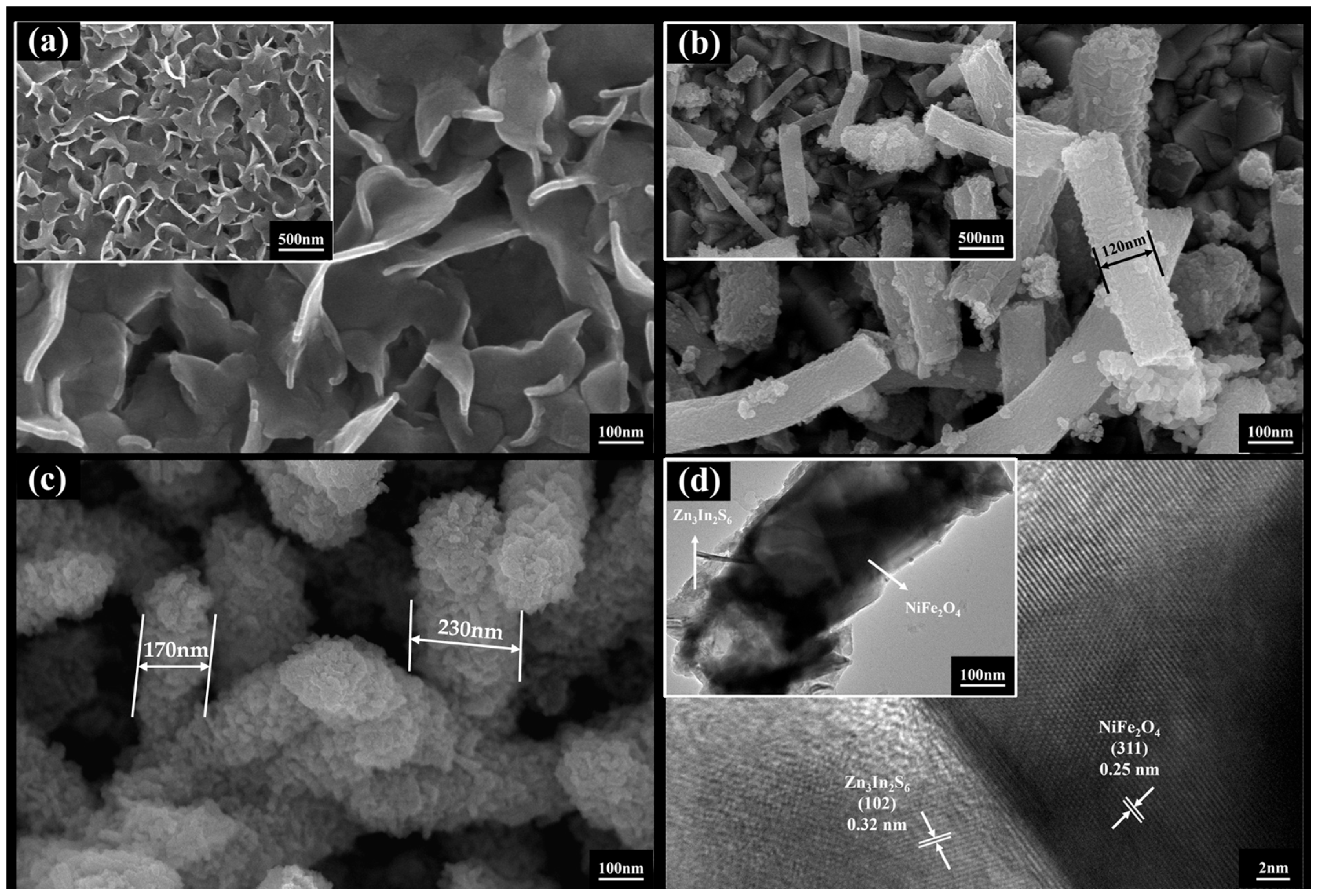
- (1)
- Two-dimensional Zn3In2S6 interlaces with and grows on the surface of one-dimensional NiFe2O4 nanofibers, and lattice information corresponding to the NiFe2O4 (311) crystal faces and Zn3In2S6 (102) crystal faces can be clearly identified. Furthermore, the diffraction peaks of NiFe2O4 and Zn3In2S6 were both found in the XRD curve of Zn3In2S6/NiFe2O4. The Zn3In2S6/NiFe2O4 composite material was successfully prepared.
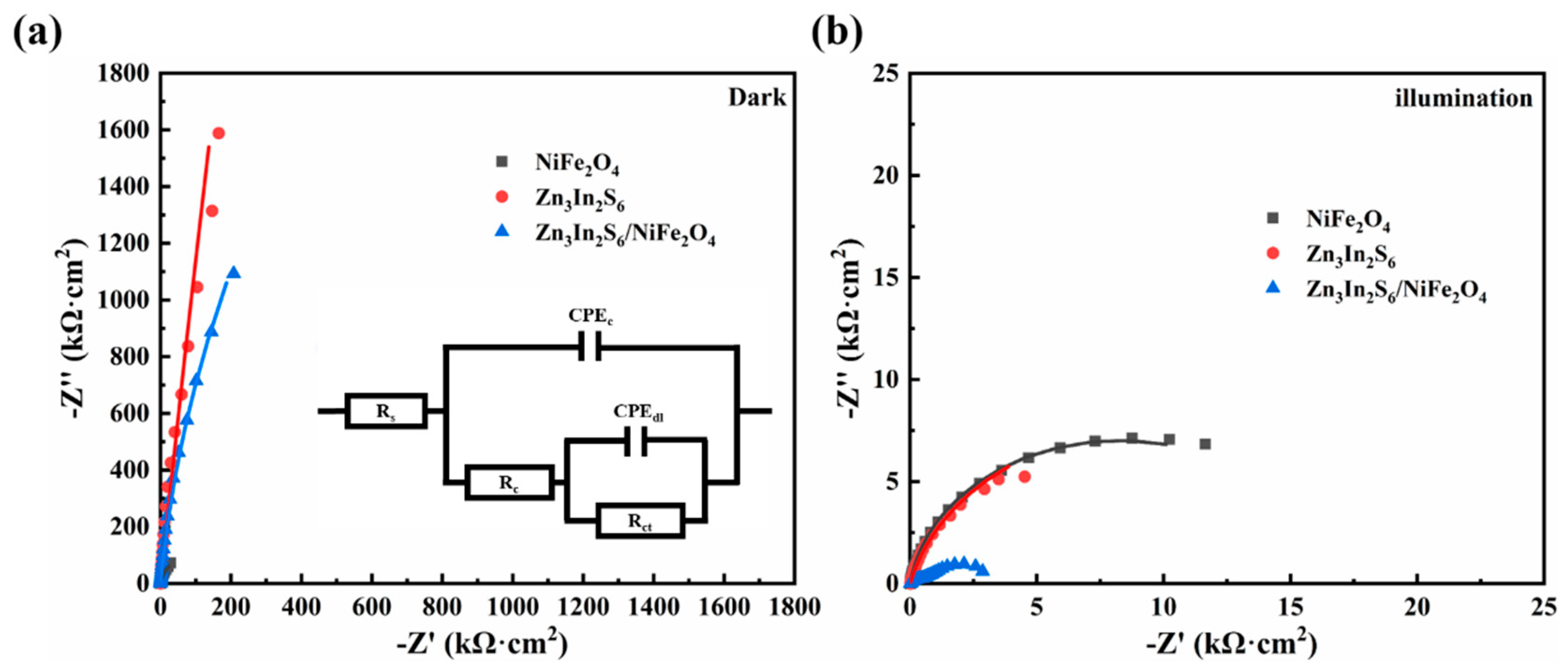
- (2)
- The construction of the energy band of the Zn3In2S6/NiFe2O4 composite material led to optical absorption thresholds that had been broadened to 630 nm. Its valence band was 1.69 eV and its conduction band was −0.63 eV. Furthermore, the Zn3In2S6/NiFe2O4 composite material has the lowest photoluminescence intensity and charge transfer resistance. It possessed a favorable light utilization capability and an excellent capacity for the separation and transfer of photogenerated electrons.
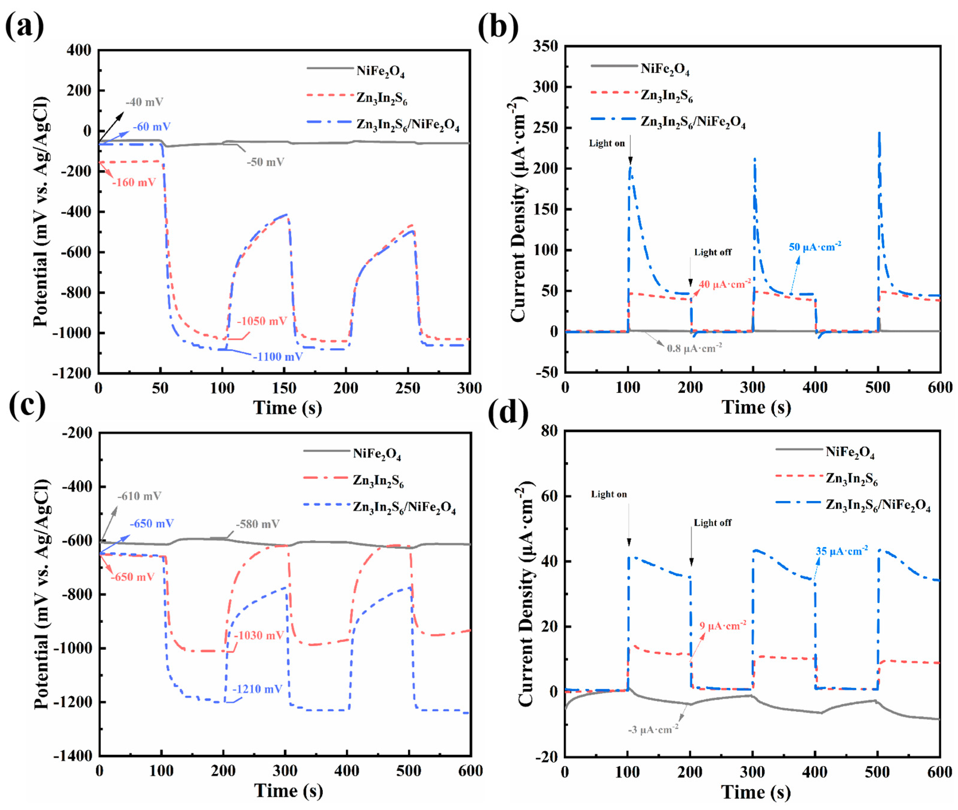
- (3)
- Compared with Zn3In2S6 and NiFe2O4, the Zn3In2S6/NiFe2O4 composite material coupled with both of the metals demonstrates superior photocathodic protection performance. When coupled with 304 SS, the open-circuit potential dropped to 1040 mV, and the photogenerated current density was 50 μA·cm−2. As for Q235 CS, the open-circuit potential had dropped to 560 mV, and the photogenerated current density was 35 μA·cm−2.
- (4)
- The charge transfer pathway between Zn3In2S6 and NiFe2O4 was consistent with the mechanism of a Z-scheme heterojunction. The photogenerated electrons and holes were concentrated in the conduction band of Zn3In2S6 and the valence band of NiFe2O4, respectively. This charge transfer mechanism preserves the strong redox capability of photogenerated carriers, thereby providing photocathodic protection for metals with low self-corrosion potentials, such as Q235 CS.
5. Conclusions
Author Contributions
Funding
Data Availability Statement
Conflicts of Interest
References
- El-Etre, A.Y. Khillah extract as inhibitor for acid corrosion of SX 316 steel. Appl. Surf. Sci. 2006, 252, 8521–8525. [Google Scholar] [CrossRef]
- Chen, W.; Wang, Z.; Xu, G.; Song, W.; Xie, Y.; Zhao, L.; Xia, M.-H.; Li, W. Friction and anti-corrosion characteristics of arc sprayed Al+Zn coatings on steel structures prepared in atmospheric environment. J. Mater. Res. Technol. 2021, 15, 6562–6573. [Google Scholar] [CrossRef]
- Momeni, M.M.; Zeinali, P. Fabrication of Ag electrodeposited-iron doped TiO2 nanotube composites for photoelectrochemical cathodic protection applications. J. Electroanal. Chem. 2021, 891, 115283. [Google Scholar] [CrossRef]
- Zhang, X.; Li, X.; Wang, X.; Jin, Z. High-efficiency dual protection of photoelectrochemical cathodic protection coating with In2O3/C3N4/CNT nanocomposites for 304 stainless steel in marine environment. Constr. Build. Mater. 2024, 453, 139096. [Google Scholar] [CrossRef]
- Kandi, D.; Martha, S.; Thirumurugan, A.; Parida, K.M. Modification of BiOI Microplates with CdS QDs for Enhancing Stability, Optical Property, Electronic Behavior toward Rhodamine B Decolorization, and Photocatalytic Hydrogen Evolution. J. Phys. Chem. C 2017, 121, 4834–4849. [Google Scholar] [CrossRef]
- Xu, S.; Zhang, Z.; Zhang, H.; Li, Z.; Peng, H.; Kawi, S.; Xie, A.; Qiu, P. In-situ fabrication of TiO2/ZIF-67 composite film with electron storage characteristics for significantly enhanced photoelectrochemical cathodic protection of 304 stainless steel. Chem. Eng. J. 2025, 503, 158693. [Google Scholar] [CrossRef]
- Hosseini, S.F.; Seyed Dorraji, M.S.; Rasoulifard, M.H. Boosting photo-charge transfer in 3D/2D TiO2@Ti3C2 MXene/Bi2S3 Schottky/Z-scheme heterojunction for photocatalytic antibiotic degradation and H2 evolution. Compos. Part B Eng. 2023, 262, 110820. [Google Scholar] [CrossRef]
- Jiang, A.; Di, Y.; Chen, S.; Zhang, D.; Chen, X.; Zhang, Z.; Zhang, X.; Dong, Q. Photocathodic protection of 304 stainless steel by coating muscovite/TiO2 heterostructure. Appl. Clay Sci. 2023, 240, 106974. [Google Scholar] [CrossRef]
- Liu, Y.; Zhu, Z.; Cheng, Y. An in-depth study of photocathodic protection of SS304 steel by electrodeposited layers of ZnO nanoparticles. Surf. Coat. Technol. 2020, 399, 126158. [Google Scholar] [CrossRef]
- Yang, Y.; Cheng, Y.F. One-step facile preparation of ZnO nanorods as high-performance photoanodes for photoelectrochemical cathodic protection. Electrochim. Acta 2018, 276, 311–318. [Google Scholar] [CrossRef]
- Bu, Y.; Chen, Z.; Ao, J.; Hou, J.; Sun, M. Study of the photoelectrochemical cathodic protection mechanism for steel based on the SrTiO3-TiO2 composite. J. Alloys Compd. 2018, 731, 1214–1224. [Google Scholar] [CrossRef]
- Cui, J.; Pei, Y. Enhanced photocathodic protection performance of Fe2O3/TiO2 heterojunction for carbon steel under simulated solar light. J. Alloys Compd. 2019, 779, 183–192. [Google Scholar] [CrossRef]
- Wang, W.; Ye, Y.; Li, G.; Yang, Z.; Duan, J.; Sun, J.; Yan, Y. High-efficiency photocathodic protection performance of novel MnIn2S4/TiO2 n-n heterojunction films for Q235 carbon steel in chloride-containing simulated concrete pore solution. J. Alloys Compd. 2023, 941, 168957. [Google Scholar] [CrossRef]
- Ren, J.; Qian, B.; Li, J.; Song, Z.; Hao, L.; Shi, J. Highly efficient polypyrrole sensitized TiO2 nanotube films for photocathodic protection of Q235 carbon steel. Corros. Sci. 2016, 111, 596–601. [Google Scholar] [CrossRef]
- Li, H.; Wang, X.; Liu, Y.; Hou, B. Ag and SnO2 co-sensitized TiO2 photoanodes for protection of 304 SS under visible light. Corros. Sci. 2014, 82, 145–153. [Google Scholar] [CrossRef]
- Wan, L.; Gao, Y.; Xia, X.-H.; Deng, Q.-R.; Shao, G. Phase selection and visible light photo-catalytic activity of Fe-doped TiO2 prepared by the hydrothermal method. Mater. Res. Bull. 2011, 46, 442–446. [Google Scholar] [CrossRef]
- Lei, C.-X.; Zhou, H.; Wang, C.; Feng, Z.-D. Self-assembly of ordered mesoporous TiO2 thin films as photoanodes for cathodic protection of stainless steel. Electrochim. Acta 2013, 87, 245–249. [Google Scholar] [CrossRef]
- Kong, C.; Su, X.; Qing, D.; Zhao, Y.; Wang, J.; Zeng, X. Controlled synthesis of various SrTiO3 morphologies and their effects on photoelectrochemical cathodic protection performance. Ceram. Int. 2022, 48, 20228–20236. [Google Scholar] [CrossRef]
- Deng, H.; Huang, M.-C.; Weng, W.-H.; Lin, J.-C. Photocathodic protection of iron oxide nanotube arrays fabricated on carbon steel. Surf. Coat. Technol. 2015, 266, 183–187. [Google Scholar] [CrossRef]
- Lei, J.; Shao, Q.; Wang, X.; Wei, Q.; Yang, L.; Li, H.; Huang, Y.; Hou, B. ZnFe2O4/TiO2 nanocomposite films for photocathodic protection of 304 stainless steel under visible light. Mater. Res. Bull. 2017, 95, 253–260. [Google Scholar] [CrossRef]
- Lu, X.; Liu, L.; Ge, J.; Cui, Y.; Wang, F. Morphology controlled synthesis of Co(OH)2/TiO2 p-n heterojunction photoelectrodes for efficient photocathodic protection of 304 stainless steel. Appl. Surf. Sci. 2021, 537, 148002. [Google Scholar] [CrossRef]
- Li, Z.; Jin, Z.; Jiang, H.; Cai, J.; Cao, Y.; Zhang, X.; Hou, B. Manganese indium sulfide/indium oxide with S-scheme heterojunction for enhanced dual performance of metal in marine environment. J. Clean. Prod. 2025, 490, 144785. [Google Scholar] [CrossRef]
- Cao, W.; Wang, W.; Yang, Z.; Wang, W.; Chen, W.; Wu, K. Enhancing photocathodic protection performance by controlled synthesis of Bi/BiOBr/TiO2 NTAs Z-scheme heterojunction films. J. Alloys Compd. 2023, 960, 170675. [Google Scholar] [CrossRef]
- Chang, Y.; Suo, K.; Wang, Y.; Ren, X.; Cao, J. In2S3@TiO2/In2S3 Z-Scheme Heterojunction with Synergistic Effect for Enhanced Photocathodic Protection of Steel. Molecules 2023, 28, 6554. [Google Scholar] [CrossRef]
- Jin, Z.; Liu, Y.; Jiang, H.; Zhang, X. Enhanced photocathodic protection on 304 SS in marine environment by Z-Scheme polydopamine-modified CdS. Constr. Build. Mater. 2024, 416, 135216. [Google Scholar] [CrossRef]
- Xu, S.; Li, Z.; Wen, J.; Qiu, P.; Xie, A.; Peng, H. Review of TiO2-Based Heterojunction Coatings in Photocathodic Protection. ACS Appl. Nano Mater. 2024, 7, 8464–8488. [Google Scholar] [CrossRef]
- Deng, F.; Peng, J.; Li, X.; Luo, X.; Ganguly, P.; Pillai, S.C.; Ren, B.; Ding, L.; Dionysiou, D.D. Metal sulfide-based Z-scheme heterojunctions in photocatalytic removal of contaminants, H2 evolution and CO2 reduction: Current status and future perspectives. J. Clean. Prod. 2023, 416, 137957. [Google Scholar] [CrossRef]
- Xu, S.; Zhang, K.; Du, L.; Gong, D.; Lu, G.; Qiu, P. Zn3In2S6/TiO2 Nanocomposites for Highly Efficient Photocathodic Protection to Carbon Steel. ACS Appl. Nano Mater. 2022, 5, 18297–18306. [Google Scholar] [CrossRef]
- She, H.; Wang, Y.; Zhou, H.; Li, Y.; Wang, L.; Huang, J.; Wang, Q. Preparation of Zn3In2S6/TiO2 for Enhanced CO2 Photocatalytic Reduction Activity Via Z-scheme Electron Transfer. ChemCatChem 2018, 11, 753–759. [Google Scholar] [CrossRef]
- Ni, L.; Xiao, Y.; Zhou, X.; Jiang, Y.; Liu, Y.; Zhang, W.; Zhang, J.; Liu, Z. Significantly Enhanced Photocatalytic Performance of the g-C3N4/Sulfur-Vacancy-Containing Zn3In2S6 Heterostructure for Photocatalytic H2 and H2O2 Generation by Coupling Defects with Heterojunction Engineering. Inorg. Chem. 2022, 61, 19552–19566. [Google Scholar] [CrossRef]
- Fan, Q.-Q.; Niu, C.-G.; Guo, H.; Huang, D.-W.; Dong, Z.-T.; Yang, Y.-Y.; Liu, H.-Y.; Li, L.; Qin, M.-Z. Insights into the role of reactive oxygen species in photocatalytic H2O2 generation and OTC removal over a novel BN/Zn3In2S6 heterojunction. J. Hazard. Mater. 2022, 438, 129483. [Google Scholar] [CrossRef] [PubMed]
- Wang, D.; Xu, Y.; Jing, L.; Xie, M.; Song, Y.; Xu, H.; Li, H.; Xie, J. In situ construction efficient visible-light-driven three-dimensional Polypyrrole/Zn3In2S6 nanoflower to systematically explore the photoreduction of Cr(VI): Performance, factors and mechanism. J. Hazard. Mater. 2020, 384, 121480. [Google Scholar] [CrossRef] [PubMed]
- Li, Z.; Zhang, X.; Jin, Z.; Jiang, H.; Wang, X.; Chen, Y.; Zhang, Y.; Hou, B. Enhanced anticorrosion mechanism of photocathodic protection coatings with zinc indium sulfide/titanium oxide Z-scheme heterojunctions. Constr. Build. Mater. 2024, 453, 139109. [Google Scholar] [CrossRef]
- Tan, D.D.; Bi, D.F.; Shi, P.H.; Xu, S.H. Preparation and Photocatalytic Property of TiO2/NiFe2O4Composite Photocatalysts. Adv. Mater. Res. 2012, 518–523, 775–779. [Google Scholar] [CrossRef]
- Jiang, Z.; Chen, L.; Shi, N.; Ji, L. Synthesis and photocatalytic properties of BiOI/NiFe2O4 composites. Mater. Res. Express 2019, 6, 066207. [Google Scholar] [CrossRef]
- Hariharasuthan, R.; Chitradevi, S.; Radha, K.S.; Chithambaram, V. Characterization of NiFe2O4 (Nickel Ferrite) nanoparticles with very low magnetic saturation synthesized via co-precipitation method. Appl. Phys. A 2022, 128, 1045. [Google Scholar] [CrossRef]
- Xiong, S.; Liu, X.; Shen, Z.; Hu, Z.; Yang, H.; Hao, J.; Cai, J.; Yang, J. Selective Oxidation of 5-Hydroxymethyl Furfural Coupled with H2 Production over Surface Sulfur Vacancy-Rich Zn3In2S6/Bi2MoO6 Heterojunction Photocatalyst. Inorg. Chem. 2023, 62, 20120–20128. [Google Scholar] [CrossRef]
- Wang, J.; Yang, G.; Wang, L.; Yan, W. Synthesis of one-dimensional NiFe2O4 nanostructures: Tunable morphology and high-performance anode materials for Li ion batteries. J. Mater. Chem. A 2016, 4, 8620–8629. [Google Scholar] [CrossRef]
- Boubaker, K. Optimization of ZnO sheets dimension in terms of ductility, micro-indentation, mechanical resistance, Amlouk-Boubaker optothermal expansivity and crystallites size. Mater. Sci. Eng. A 2011, 528, 1455–1457. [Google Scholar] [CrossRef]
- Atkins, E. Elements of X-Ray Diffraction. Phys. Bull. 1978, 29, 572. [Google Scholar] [CrossRef]
- Thomas, A.; Fischer, A.; Goettmann, F.; Antonietti, M.; Müller, J.-O.; Schlögl, R.; Carlsson, J.M. Graphitic carbon nitride materials: Variation of structure and morphology and their use as metal-free catalysts. J. Mater. Chem. 2008, 18, 4893–4908. [Google Scholar] [CrossRef]
- Liu, H.; Sun, F.; Li, X.; Ma, Q.; Liu, G.; Yu, H.; Yu, W.; Dong, X.; Su, Z. g-C3N4/TiO2/ZnIn2S4 graphene aerogel photocatalysts with double S-scheme heterostructure for improving photocatalytic multifunctional performances. Compos. Part B Eng. 2023, 259, 110746. [Google Scholar] [CrossRef]
- Butler, M.A. Photoelectrolysis and physical properties of the semiconducting electrode WO2. J. Appl. Phys. 1977, 48, 1914–1920. [Google Scholar] [CrossRef]
- Jing, J.; Chen, Z.; Bu, Y.; Sun, M.; Zheng, W.; Li, W. Significantly enhanced photoelectrochemical cathodic protection performance of hydrogen treated Cr-doped SrTiO3 by Cr6+ reduction and oxygen vacancy modification. Electrochim. Acta 2019, 304, 386–395. [Google Scholar] [CrossRef]
- Li, B.; Lai, C.; Zeng, G.; Qin, L.; Yi, H.; Huang, D.; Zhou, C.; Liu, X.; Cheng, M.; Xu, P.; et al. Facile Hydrothermal Synthesis of Z-Scheme Bi2Fe4O9/Bi2WO6 Heterojunction Photocatalyst with Enhanced Visible Light Photocatalytic Activity. ACS Appl. Mater. Interfaces 2018, 10, 18824–18836. [Google Scholar] [CrossRef]
- Dong, F.; Wang, Z.; Li, Y.; Ho, W.-K.; Lee, S.C. Immobilization of Polymeric g-C3N4 on Structured Ceramic Foam for Efficient Visible Light Photocatalytic Air Purification with Real Indoor Illumination. Environ. Sci. Technol. 2014, 48, 10345–10353. [Google Scholar] [CrossRef]


| Photoanode | Flat Charged Level (V vs. Ag/AgCl) | Conductive Tape (eV) | Bandgap Width (eV) |
|---|---|---|---|
| Zn3In2S6 | −0.80 | −0.80 | 2.72 |
| NiFe2O4 | −0.28 | −0.28 | 2.41 |
| Zn3In2S6/NiFe2O4 | −0.63 | −0.63 | 2.32 |
| Sample | Ecorr or Ecouple (V) | Icorr or Icouple (μA·cm−2) | βa (V decay−1) | βc (V decay−1) |
|---|---|---|---|---|
| 304 SS | −0.16 | 0.92 | 3.29 | −8.52 |
| NiFe2O4 dark | −0.07 | 1.19 | 15.54 | −5.21 |
| NiFe2O4 illumination | −0.90 | 3.98 | 23.16 | −5.49 |
| Zn3In2S6 dark | −0.12 | 0.63 | 1.93 | −7.28 |
| Zn3In2S6 illumination | −0.62 | 5.30 | 8.79 | −5.49 |
| Zn3In2S6/NiFe2O4 dark | −0.21 | 1.34 | 1.93 | −7.28 |
| Zn3In2S6/NiFe2O4 illumination | −0.78 | 10 | 2.03 | −6.18 |
| Sample | Ecorr or Ecouple (V) | Icorr or Icouple (μA·cm−2) | βa (V decay−1) | βc (V decay−1) |
|---|---|---|---|---|
| Q235 CS | −0.68 | 1.04 | 13.71 | −13.68 |
| NiFe2O4 dark | −0.68 | 5.01 | 8.24 | −9.25 |
| NiFe2O4 illumination | −0.67 | 8.33 | 7.35 | −5.17 |
| Zn3In2S6 dark | −0.71 | 3.71 | 20.14 | −4.92 |
| Zn3In2S6 illumination | −0.96 | 16.81 | 11.26 | −5.38 |
| Zn3In2S6/NiFe2O4 dark | −0.72 | 5.24 | 17.25 | −6.84 |
| Zn3In2S6/NiFe2O4 illumination | −1.14 | 32.48 | 6.02 | −8.55 |
| Sample | Rs (kΩ·cm2) | Rct (kΩ·cm2) | CPEc | Rf (kΩ·cm2) | CPEdl | ||
|---|---|---|---|---|---|---|---|
| Yo(SnΩ−1cm−2) | n1 | Ydl(SnΩ−1cm−2) | n2 | ||||
| NiFe2O4 dark | 13.87 | 2.3 × 10⁵ | 5.5 × 10⁻⁶ | 1 | 5.1 | 1.2 × 10⁻⁵ | 0.90 |
| Zn3In2S6 dark | 14.49 | 3.7 × 10⁶ | 1.1 × 10⁻⁶ | 1 | 48.7 | 7.8 × 10⁻⁶ | 0.94 |
| Zn3In2S6/NiFe2O4 dark | 13.22 | 1.1 × 10⁷ | 7.1 × 10⁻⁶ | 0.95 | 1.7 × 10² | 3.1 × 10⁻⁶ | 0.95 |
| NiFe2O4 light | 15.56 | 1.0 × 10³ | 5.52 × 10⁻⁵ | 1 | 1.5 × 10⁴ | 8.8 × 10⁻⁴ | 0.92 |
| Zn3In2S6 light | 17.03 | 1.9 × 10² | 3.4 × 10⁻⁴ | 0.76 | 7.8 × 10² | 2.9 × 10⁻³ | 0.96 |
| Zn3In2S6/NiFe2O4 light | 15.15 | 1.7 × 10² | 1.7 × 10⁻⁵ | 0.86 | 1.8 × 10⁴ | 1.4 × 10⁻⁴ | 1 |
| 13.87 | 2.3 × 10⁵ | 5.5 × 10⁻⁶ | 1 | 5.1 | 1.2 × 10⁻⁵ | 0.90 | |
Disclaimer/Publisher’s Note: The statements, opinions and data contained in all publications are solely those of the individual author(s) and contributor(s) and not of MDPI and/or the editor(s). MDPI and/or the editor(s) disclaim responsibility for any injury to people or property resulting from any ideas, methods, instructions or products referred to in the content. |
© 2025 by the authors. Licensee MDPI, Basel, Switzerland. This article is an open access article distributed under the terms and conditions of the Creative Commons Attribution (CC BY) license (https://creativecommons.org/licenses/by/4.0/).
Share and Cite
Wang, X.; Chen, Y.; Zhang, X. Design of a One-Dimensional Zn3In2S6/NiFe2O4 Composite Material and Its Photocathodic Protection Mechanism Against Corrosion. Buildings 2025, 15, 958. https://doi.org/10.3390/buildings15060958
Wang X, Chen Y, Zhang X. Design of a One-Dimensional Zn3In2S6/NiFe2O4 Composite Material and Its Photocathodic Protection Mechanism Against Corrosion. Buildings. 2025; 15(6):958. https://doi.org/10.3390/buildings15060958
Chicago/Turabian StyleWang, Xiaotong, Yuehua Chen, and Xiaoying Zhang. 2025. "Design of a One-Dimensional Zn3In2S6/NiFe2O4 Composite Material and Its Photocathodic Protection Mechanism Against Corrosion" Buildings 15, no. 6: 958. https://doi.org/10.3390/buildings15060958
APA StyleWang, X., Chen, Y., & Zhang, X. (2025). Design of a One-Dimensional Zn3In2S6/NiFe2O4 Composite Material and Its Photocathodic Protection Mechanism Against Corrosion. Buildings, 15(6), 958. https://doi.org/10.3390/buildings15060958