Article

Using Near-Surface-Mounted Small-Diameter Steel Wires to Improve Construction Efficiency in Strengthening Substandard Lapped Spliced Reinforced Concrete Beams

1
Department of Civil Engineering, Faculty of Engineering, Kafrelsheikh University, Kafrelsheikh 33516, Egypt
2
Department of Civil Engineering, College of Engineering and Architecture, Umm Al-Qura University, Makkah 24382, Saudi Arabia
3
Department of Civil Engineering, Necmettin Erbakan University, Konya 42090, Türkiye
4
Department of Technical Sciences, Western Caspian University, Baku 1001, Azerbaijan
*
Authors to whom correspondence should be addressed.
Buildings 2025, 15(6), 957; https://doi.org/10.3390/buildings15060957
Submission received: 18 February 2025 / Revised: 13 March 2025 / Accepted: 14 March 2025 / Published: 18 March 2025

Abstract

:
Strengthening lapped spliced reinforced concrete (RC) beams using tiny-diameter steel wires as near-surface-mounted (NSM) rods has not been carried out previously. Thus, the purpose of this work is to examine the behavior of RC beams with insufficient lap splices that are strengthened by NSM steel wires with different schemes to improve durability, efficiency, and effectiveness. At the middle of the beam, a splice length equal to 25 times the diameter of the rebar was used to join two tension bars. Many different schemes were implemented in strengthening the splice region, such as attaching longitudinal wires to the sides and/or bottom of the beam in different quantities with/without end anchorage, placing perpendicular and inclined U-shaped wires at the splice region in different quantities, and implementing a network of intersecting and opposite wires in two different directions. The effect of variables on the behavior of strengthened beams was studied. The findings proved that when the longitudinal wire reinforcement-to-lapped rebars area ratio was 9.4%, 18.7%, and 28%, the ultimate load of the beams was improved by 15.71%, 71.43%, and 104.57%, respectively. When the transverse U-shaped wire reinforcement ratio was 0.036, 0.051, 0.064, 0.075, and 0.150, the ultimate load of the beams was improved by 3.7%, 20%, 31.4%, 50%, and 80%, respectively, and the ultimate deflection was enhanced by 2%, 32%, 19%, 67%, and 62.4% compared to the unstrengthened beam.

1. Introduction

A number of catastrophic construction failures in recent large-scale earthquakes (e.g., Morocco 2022, Italy 2012, and China 2008) have been attributed to short lap-spliced reinforcement, and this means a high risk of construction failure in building projects. Typically, this kind of reinforcement was installed at beam–column connections or at high-demand locations like the column–footing link. These lap cuts frequently have an expanse of 20–24 times the bar diameter, which is less than the required splice length according to bond regulations and contemporary design guidelines (ACI Committee 408 [1]; fib 2013 [2]). These guidelines frequently call for a splice length greater than (40–60) d, where d is the rebar’s diameter. For this reason, these resources are not sufficient to properly mobilize the spliced rods. Inadequate planning and execution can result in a lap splice that requires reinforcement because of its insufficient bond strength. One of these three techniques—lap splices, welded splices, or mechanical couplers—is typically used to transfer tension from one bar to another. Lap splices are the most commonly used of these. Structural enhancement can improve a structure’s usefulness and effectiveness while also assisting its adjustment to the shifting demands of society. In RC constructions, lap splices were found in the beams, slab-to-column connections, and column–footing connections. The tensile strength of splices in RC beams was the subject of this investigation.
The improved bond behavior of steel rebars spliced into laps leads to improved performance in reinforced concrete (RC) beams. All strengthening solutions applied to faulty RC beams delay or prevent the failure of the lapped rebars at the beam soffit concrete cover splitting by functioning as an external limitation at the splice location. Tensioned bars may have an unstable splitting break or a pull-out failure [3]. Lap splices are required to transmit the tension force and provide an adequate deformation capacity. This is particularly important if the lap is located close to an essential part of the peak moment [4].
External bonding (EB) and near-surface mounting (NSM) are the two most commonly used techniques. The most popular strategies for reversing the decline in RC involvement are the NSM and EB systems. Flexural reinforcement for RC beams was carried out using the EB technique [5]. The RC constructions reinforced with EB FRP were prone to debonding due to cracks [6]. FRP was inserted using the EB technique with epoxy glue or mortar into drilled grooves in the side and/or bottom concrete covers of the beam in a range of forms, including rods and sheets. The location and configuration of CFRP bars have an impact on the degree of moment redistribution of NSM-reinforced beams [6].
It is necessary to slot the grooves into the concrete surface in NSM procedures. There are two possible uses for holes: strengthening the sidewalls of the beams against shear or flexure reinforcement in the bending faces of the RC components. The NSM composites are embedded into the grooves, and the glue is inserted and smoothed after half of the hole is filled with glue [7,8,9,10]. Numerous studies have been conducted on FRP concrete members, but the majority of these studies have focused on the EB FRP technique, with a small number also looking at bottom near-surface-mounted (BNSM) systems [11,12]. There are certain restrictions when using the near-surface-mounted bottom concrete [13]. For example, for shiny and lightly sandblasted rebars, the smallest ratio of the groove measurements to the bar diameter must be 1.5 and 2.0 times the NSM bar size, respectively. In addition, the least gross separation between the two nearest slots equals two rebar sizes, and the least net isolation between the opening and the beam border equals four rebar sizes [14]. These restrictions limit the application of the BNSM approach in beams. Many studies have been conducted on concrete structures.
Employing NSM rods and prestressing techniques enhanced shear-critical RC beams [15]. According to the findings, the shear capacity of the beams was raised by 57.8% and 70.4% by inserting five pairs of prestressing NSM rods and five pairs of internal prestressing rods. The performance of reinforced RC beams was investigated in relation to the bond length of NSM FRPs and mechanical grooves [16]. The findings showed that the load bearing capacity was marginally increased through the use of mechanical interlocking grooves. In comparison to the beam with complete bonding, a decrease in bond length resulted in a 27.2% increase in deformability and a 7.6% loss in load capacity. The impact of decreasing the NSM length on the shear strength of reinforced beams was investigated by Khol et al. [17]. Five RC T-beams were half scaled and put through flexure testing. All except one were reinforced under shear, where the partial-length NSM strips were positioned to mitigate the impact of the decreased NSM length. The results showed that the reduced NSM length had no discernible effect on the strength of the strengthened specimens. Research on the flexural strengthening of one-way reinforced concrete slabs with near-surface-mounted bars was prompted by Aljidda et al. [18]. According to the findings, NSM might boost slab load capacity by as much as 124%. Furthermore, ductility indices for reinforced slabs increased by up to 79%, indicating better ductility.
The usefulness of near-surface-mounted (NSM) rope and strip in RC beam shear strength was experimentally examined [19]. Fifteen 150 mm × 250 mm × 1200 mm beams that were intended to fail under shear were tested. In order to investigate the load displacement behavior of RC beams reinforced with NSM rope and FRP strips, the following characteristics were taken into account in each configuration: the NSM orientation angle, the distance between NSM ropes, and the strengthening scheme. The findings demonstrated that NSM rope is a useful method for reinforcing RC beams. When compared to all other configurations, the ultimate load capacity rose by 150–170% of the control specimen when using inclined NSM ropes or strips. The impact of employing carbon fiber-reinforced polymer that is installed close to the surface on the shear strength of RC beams composed of varying concrete concentrations was examined by Abdel-Jaber et al. [20]. NSM strips were installed vertically in three distinct configurations to carry out the experimental program: aligned with the internal stirrups, one vertical NSM strip separated by every two internal stirrups, and two vertical NSM strips separated by every two internal stirrups. According to the experimental findings, the failure mechanism of all beams was restricted to pure shear failure, with no debonding or rupture of the carbon strips when NSM was used. As the compressive strength of every beam increased, so did the experimental shear capacity.
Furthermore, the use of small-diameter steel wires as NSM rods is unprecedented. It is not necessary to drill holes with large diameters when using tiny diameter wires, and small holes of a shallow depth may be made. This technique works well for concrete elements that have a thin concrete cover and dense inner reinforcement, which prevents the internal bars from being grooved in order to prevent bond resistance between the bars and the concrete from being weakened. In order to enhance the side near-surface-mounted (SNSM) and bottom near-surface-mounted (BNSM) strengthening approaches, this work aims to investigate the impacts of end anchoring and the amount of NSM bars using small-diameter steel wires. Additionally, this research implemented a new NSM scheme using U-shaped NSM steel wires to replace both SNSM and BNSM wires. The quantity of U-shaped NSM steel wires and their inclination angle were among the factors assessed.

2. Aims of the Study

Rebar splicing is an inevitable difficulty in RC elements because of the limited length of reinforcement rebars, transport limitations, revisions in international standards for earthquake risk mitigation requirements, and mistakes in the design and implementation stages of construction projects. When connections are made, concrete is responsible for transmitting the tensile force between the two linked skewers. As a result, it is crucial to research the concrete’s bonding strength. Since pull-out experiments are simple and inexpensive, a lot of researchers have used them to study bond strength between reinforcing rebars and concrete, although pull-out experiments have limited design applications. The pull-out experiment does not accurately represent the actual conditions, since reinforcing bars always exist close to the concrete’s surface where the concrete coating is rather thin. Because of this, lapped spliced beams were used for the experiments in this paper, which makes the experiments appropriate. Studies have shown that the majority of the reinforcements in concrete structures today do not adhere to the current rules, due to the numerous earthquakes. As a result, researchers focused on RC parts with short splices, particularly beams, and how reinforcing or repairing them could mitigate the risk of construction failure. The most recent fortifying technique for supporting RC components that are lacking the splice length of the reinforcement rebars is called NSM. The benefits of NSM rod construction from the value engineering viewpoint include little surface preparation (apart from grooving), quick installation, the availability of all necessary equipment and materials, and their ease of use and affordability. So, this construction technique can enhance value for money and reduce risks of construction failure by improving the quality and durability of RC components without many extra resources. Numerous studies have examined the use of NSM traditional ribbed reinforcing steel rods; however, NSM small-diameter steel wires have not been examined previously, despite their availability, affordability, ease of installation, and speed. Additionally, when employing small-diameter wires, it is not essential to make cuts with large diameters, as openings of small depths can be formed. This method prevents the interior bars from being grooved, preventing the bonding strength between the rebars and the concrete from weakening, and it performs well for concrete components with a thin concrete shell and substantial internal reinforcement. Thus, using NSM small-diameter steel wires for strengthening inferior lapped spliced reinforced concrete beams is the main focus of this research.

3. Experiments

3.1. Materials

3.1.1. Concrete

The identical concrete blend, including cement, water, and fine and coarse aggregates, was used to cast each beam. Shredded basalt with a size range from 0.3 mm to 12 mm is known as coarse aggregate. Its granules are sharply angled, its surface is hard, and it is pure. The fine particles were made from sand from river deposits. The cement used was regular Portland cement with a 42 MPa capacity. Chloride-free tap water was used for the mixing process. 300 kg/m3 of cement, 150 L of water, 600 kg/m3 sand, and 1200 kg/m3 basalt make up the mixture. Three standard 150 mm-long cubes were formed throughout the beam casting process. After 28 days, three cubes were tested under compression load and then the average was obtained. The compressive strength of the concrete mixture was discovered to be 28 MPa.

3.1.2. Internal Reinforcement

The internal reinforcement of the beams was carried out using two distinct kinds of rebars: one had an even surface and a diameter of 8 mm, while the other type had a deformed surface and a diameter of 10 mm. A 10 mm rod was used on the tension side of the beams at the splicing. The rods underwent tension experiments to ascertain their characteristics. Eight- and ten-millimeter rods were found to have tensile strengths of 380 and 620 MPa, respectively. Furthermore, 199 GPa is the elasticity modulus for both kinds of rods. For the rods that are 8 mm and 10 mm, the amount of elongation is 19 and 12%, respectively. The bonding quality of the rebar at the tension side of the beams is significantly influenced by the geometric characteristics of the rebar used in the splice zone (10 mm rod). The tension side of the beams is strengthened by a 10 mm ribbed deformed bar, as shown in Figure 1a. The rod’s surface had spiral ribs. The ribbed rod had a total diameter of 11.1 mm and a net diameter of 9.5 mm. The ribs measured 3.1 mm in width, 0.8 mm in height, 6 mm in pitch, and 45 degrees in inclination with respect to the longitudinal direction.

3.1.3. Steel Wires

In the NSM procedure, a 2.5 mm smooth-surface wire was employed (Figure 1b). Its mechanical qualities were ascertained by conducting tension experiments. For this wire, the elasticity was around 200 GPa. With regard to the 2.5 mm wire, the yield, ultimate tension, and extension were 250.3 MPa, 343.7 MPa, and 34%, respectively.

3.1.4. Adhesive

Sikadur 31CF was the epoxy material used in this study. This product was manufactured by Sika Egypt Company in Al Obour City, Egypt. This chemical, which is defined as an extremely strong epoxy glue, is used to connect NSM wires to a concrete surface. The advantages of this epoxy include its excellent adhesion, ability to be used without priming, lack of slumping, and strong resistance to chemicals.

3.2. Lap-Spliced Beam Samples

Ten similar lapped spliced beams made of the same mix were cast; nine of them were strengthened and one of them was left unstrengthened to serve as a reference sample (B0). The beams were then subjected to flexure testing. Every beam had the same dimensions and internal reinforcement (Figure 2). The beams measured 1500 mm in length and 120 × 200 mm in cross-section. The loaded length was 1400 mm. Two 10 mm steel bars served as the beams’ tensile rebars, while two 8 mm rebars reinforced the compression face. In the middle, a splice length equal to 25 times the diameter of the rebar was used to join two tension bars. The beam span consisted of the center, which had a bending moment only, and two ends experiencing comparable shear forces. The middle splice length was chosen to be 25 times the bar’s diameter, which is regarded as an inadequate splice when the minimum splice length recommended by the ACI [1] was about 50 times the diameter of the rebar. Furthermore, the four-point flexure experiment was chosen to provide a pure bending range at the splice spot, meaning that only tensile load was transferred to the lap-spliced rebars. Also, the constant bending distance was selected as 450 mm to be larger than the splice length (25 mm). Shear is reinforced by two leg ties, which are made of 8 mm bars spaced 50 mm apart along the shear spans. To prevent shear failure and enable NSM strengthening to increase beam capacity, a significant shear reinforcement ratio was used. The bending length eliminated any stirrups in order to distinguish the role that the strengthening technique plays in increasing the effectiveness of the short splices in the tested beams. The tension rebar’s side and bottom cover (c) measured 23 mm (Figure 2).

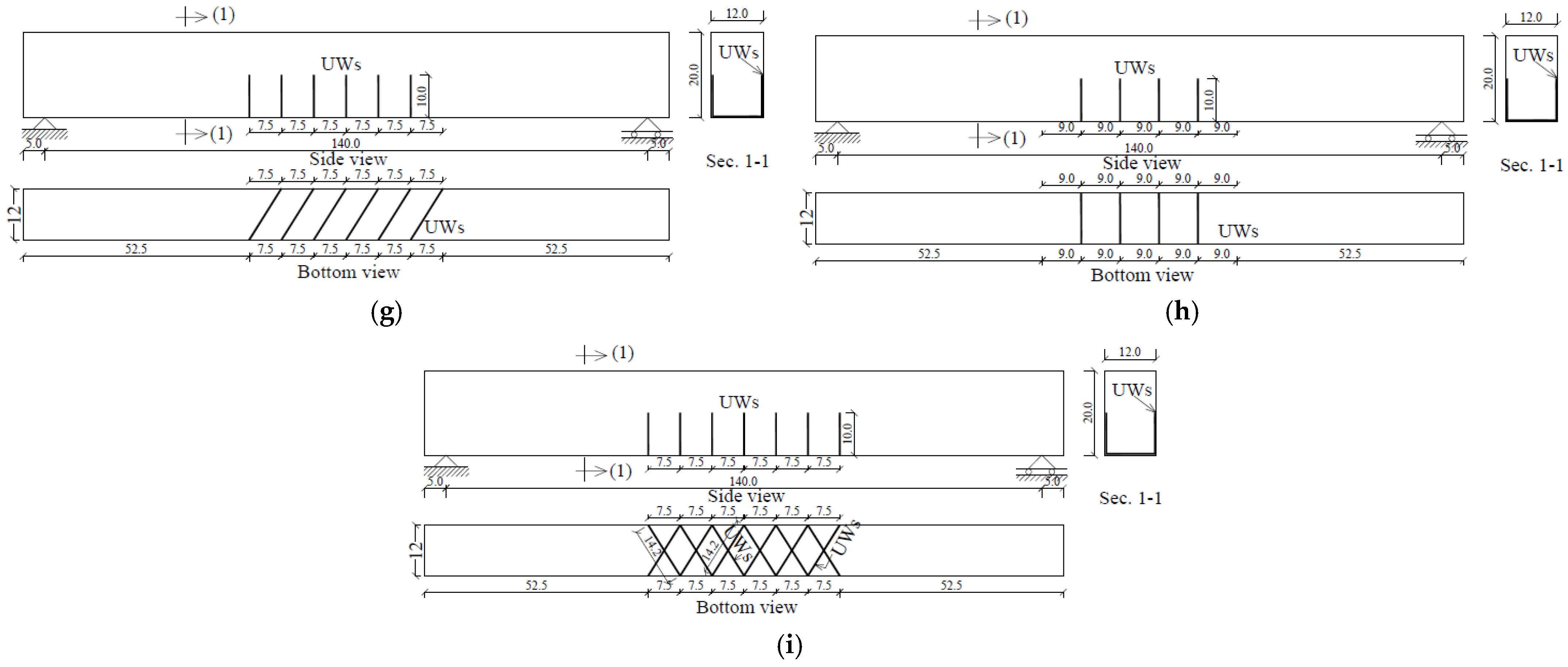
3.3. Implementing NSM

NSM strengthening was used in this study with steel wires of a 2.5 mm diameter. These wires have the benefit of requiring narrow, shallow holes for both width and depth. It is extremely easy to use and just needs small amounts of epoxy. It is possible to place several parallel, neighboring wires in a relatively tiny area (10 mm). Additionally, these easily formed wires make it straightforward to create a U-shape that simultaneously encompasses the bottom and sides of the beam. Thanks to these wires, it is possible to create wire intersections. In the splice area at the bottom of the beam, wires were installed in two intersecting directions for this study. It is feasible to create many parallel wires in one direction, and then, by interleaving them, implement parallel wires in the direction perpendicular to the initial wires. In order to allow epoxy to bond the wire to the concrete, the grooves in the current work are 4.5 by 4.5 mm, making them 1 mm larger on all sides than the NSM wire diameter. The NSM method involves creating a gap in the concrete’s surface and thoroughly washing it with water and air to remove dust. The epoxy is then poured into the slot, the wire is buried, and it is leveled far above the wire.
Wires were used in this work to create a variety of designs, including the straight-line form, which was adhered to the side or bottom of the beam (samples B1, B2, B3, and B2*). Additionally, the U-shape was employed in four designs with varying widths and two legs, each leg measuring 100 mm. At the endpoints of straight wires, the first style serves as an anchor or tie (B2*). The second style is a U-shaped form where the wire is oriented perpendicular to the beam’s direction (B4*). The third style is for the wire to be angled toward the beam (B4, B5, and B6). The fourth step is to simultaneously install an oblique wire and a perpendicular wire in the opposite direction (B6*). NSM was carried out along the constant moment span (450 mm) in all nine strengthened beams.
One straight NSM wire (SW) and another straight NSM wire (BW) were adhered to the side and soffit of beam B1, respectively (Figure 3a). In addition, two SWs were added to the sidewalls and two BWs were completed at the soffit of beam B2 (Figure 3b). Three SWs were added to the sidewalls, and three BWs were completed at the beam B3’s soffit (Figure 3c). The NSM scheme utilized in B2 was duplicated in B3 (Figure 3d). In addition, three U-shaped wires perpendicular to the beam axis were positioned at the ends of longitudinal straight wires as end anchorages to prevent the NSM wire from debonding at high loading and prevent brittle failure.
A U-shaped wire pattern was laid out on stationary beams, either inclined or perpendicular to the beam axis. This design features two 100 mm legs that are bonded to the sides of the beam with varying widths between the legs. U-shaped wires were placed in all beams except B4* to improve the exterior confinement around the spliced rebars and to withstand some of the tension force within the spliced rebars. Regarding Beam B4*, U-shaped wires perpendicular to the beam’s axis were used only for the exterior enclosure (Figure 3h).
In beams B4 (Figure 3e), B5 (Figure 3f), and B6 (Figure 3g), there were four, five, and six U-shaped wires (UWs), respectively. The only difference between B4 and B4* was the angle used to assess the effect of UW inclination on splice performance. Both B4 and B5 produced the same number of Uws—four. Two sets of six wires were installed in B6* at opposite angles. Six-millimeter-deep holes were cut during the installation of the initial six wires, to allow the subsequent six wires to pass over them. The procedures for implementing strengthening schemes on the sides and bottoms of the beams are depicted in Figure 4. The original beam was painted white and the strengthening was painted orange to facilitate the distinction between collapse within the NSM strengthening material and cracks in the beam itself (Figure 4g,h). Each sample was performed once in the current work program.

3.4. Loading Device

On the beams, four-point flexure testing was conducted. As shown in Figure 2, the steel beam was loaded using a hydraulic jack, which split the load into two equal parts (P/2). The middle portion of the beam’s length was under stress due to a constant bending moment at the splice zone across a 450 mm range. Roller and a hinge supports were all that were required to support the two ends of the beam. Furthermore, splits on the surface of the beam were noticed. The beam’s deflection at the midpoint was measured using the deflection sensor. In these tests, the loading rate was 3 kN/min. This system is force-controlled because this type was available in the laboratory. This slow rate was chosen to avoid affecting the beam’s bearing capacity while the anatomy could be observed and recorded.

4. Results and Analysis

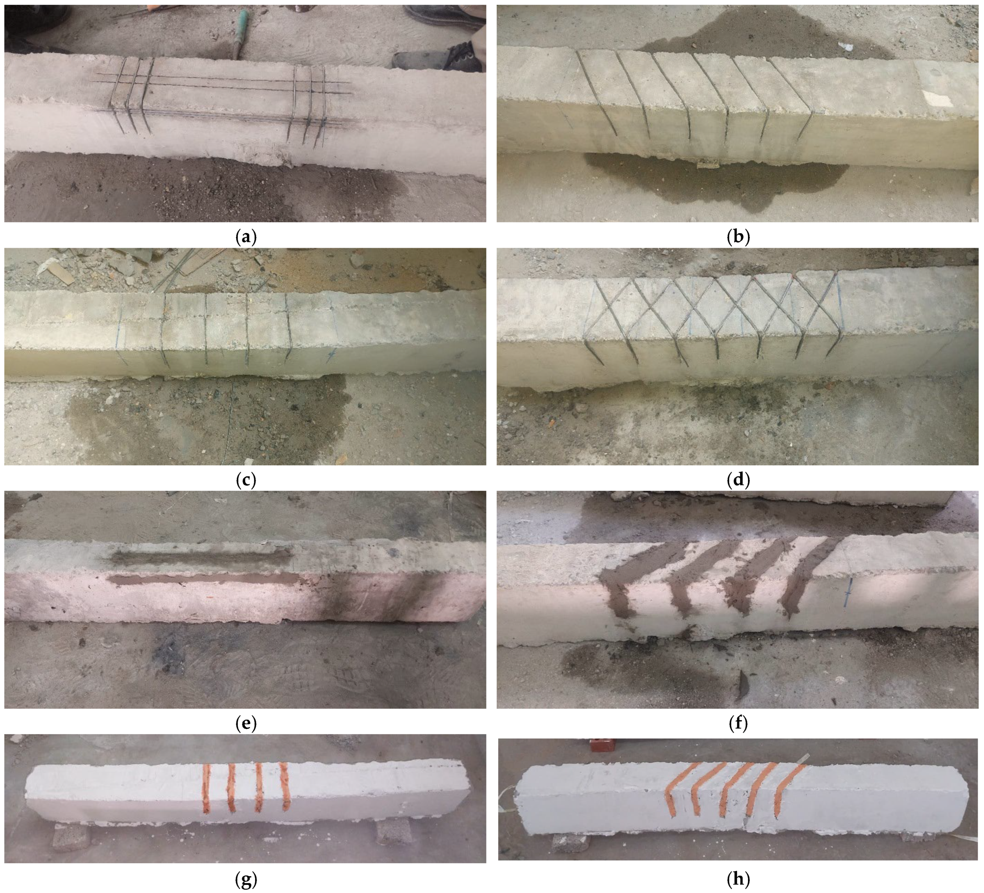
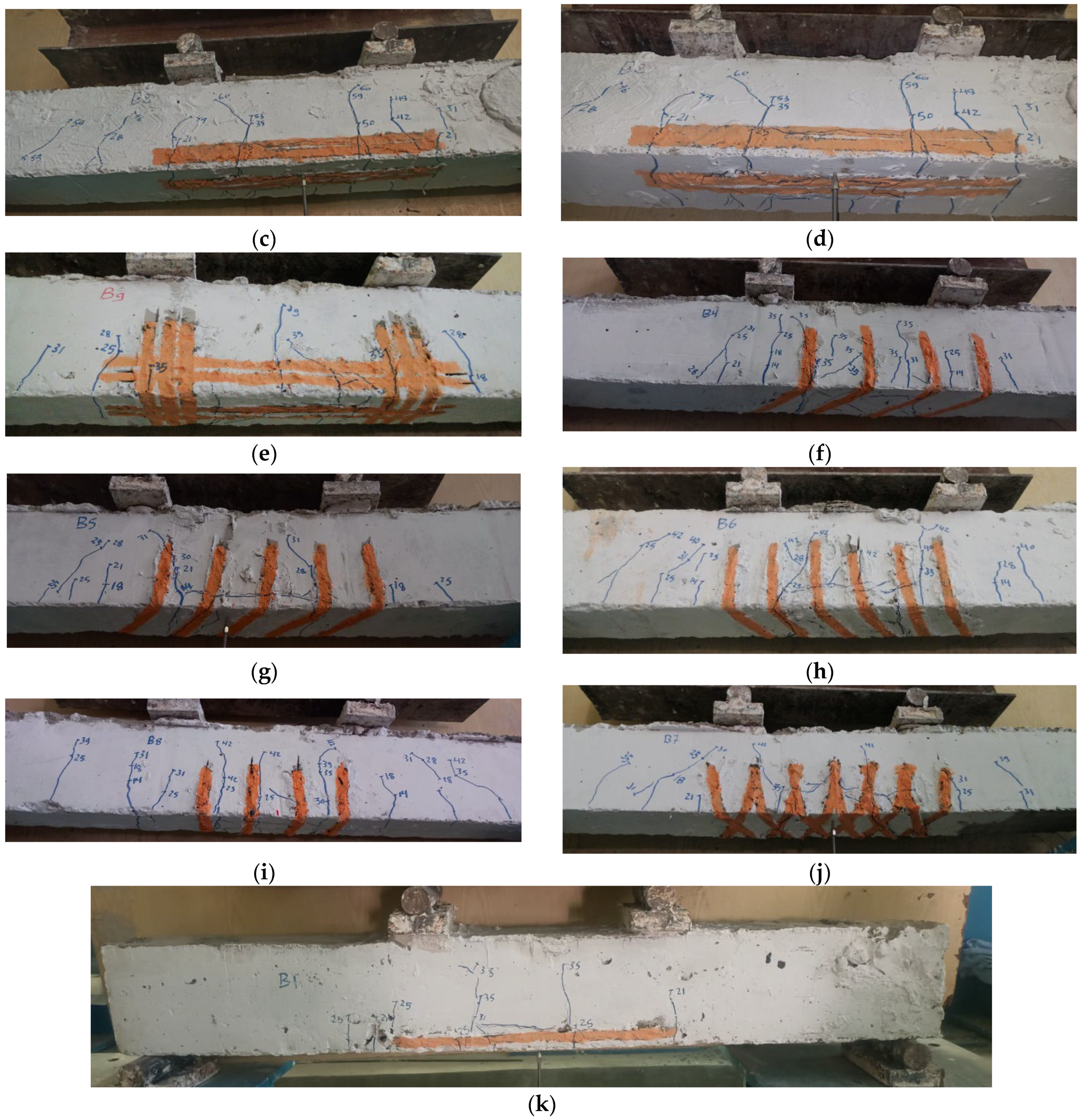
4.1. Failure and Cracking Analysis

Figure 5 shows the failures of beams at the splice region. At a load ranging from 25 to 40 kN, a vertical crack appeared at both ends of the lapped spliced rebars in the middle of the beam. This crack starts from the bottom of the beam and heads upwards. This crack appeared because the length of the splice was insufficient to transfer the tensile forces from the lower bars to each other. This failure is classified as concrete splitting (CS) at the splice ends. The beams B0 (Figure 5a), B1 (Figure 5b), and B2 (Figure 5c) failed due to CS. Additionally, partial debonding at the wire–epoxy interface occurred in beam B2. In B3, which was provided with three SWs and BWs (Figure 5d), partial debonding at the wire–epoxy interface occurred, causing the collapse. Although two vertical cracks occurred at the splice of B3, reinforcement with longitudinal wires at both sides and the soffit of the beam was able to prevent these cracks from opening. Increasing the number of wires on the beam surface from the tensile side improved cracking, reducing the propagation of cracks in the maximum torque area.
Performing end anchorage in beam B2* prevented debonding at the ends of SWs and BWs, but was not capable of preventing CS at the splice ends (Figure 5e). The beams B4, B5, B6, B4*, and B6* showed CS at the splice ends. In addition, debonding at the ends of Uws occurred (Figure 5f–h). In all the tested beams, the collapse occurred in the joint area due to a defect in this location (Figure 5i). The short length of the joint prevented the cracks from appearing along the beam span. Another reason for this occurrence was that the shear reinforcement added to the sides of the load points, which prevents collapse at the joint site, even with strengthening.

4.2. Crack Load

Figure 6 shows the cracking load of the beams at the ends of the spliced rebars. The crack load was 25 kN in beams B0, B1, B2, and B4*. Using one or two longitudinal wires on the sides and bottom of the beams B1 and B2 did not delay the cracking load. Perhaps the reason for this is that the amount of NSM reinforcement added to the beam section was relatively small. Also, the U-shaped wires did not delay the cracking load of B4*. The reason for this may be the insufficient wires in these samples, as they could not improve the crack resistance of the beams, especially with the presence of a short splice.
All other methods implemented in the remaining beams succeeded in significantly delaying the cracking load. The cracking load of beam B3, carried out with three SWs and BWs, reached 40 kN, while in the control beam B0, it was only 25 kN. The rate of enhancement reached 60% in the cracking load of the B3. The maximum enhancement rate of 60% occurred in B3 because the number of wires reached nine. Also, when the number of wires reached six in B2* and end anchorages were performed, the increase in the crack load reached 40%. The increased reinforcement in the splice parallel to the lapped bars is what caused these improvements. The tensile force on the spliced bars decreased as a result of enhanced reinforcement, helping to carry a portion of the tensile force brought on by the bending moment. The cracking load obviously improved as a consequence.

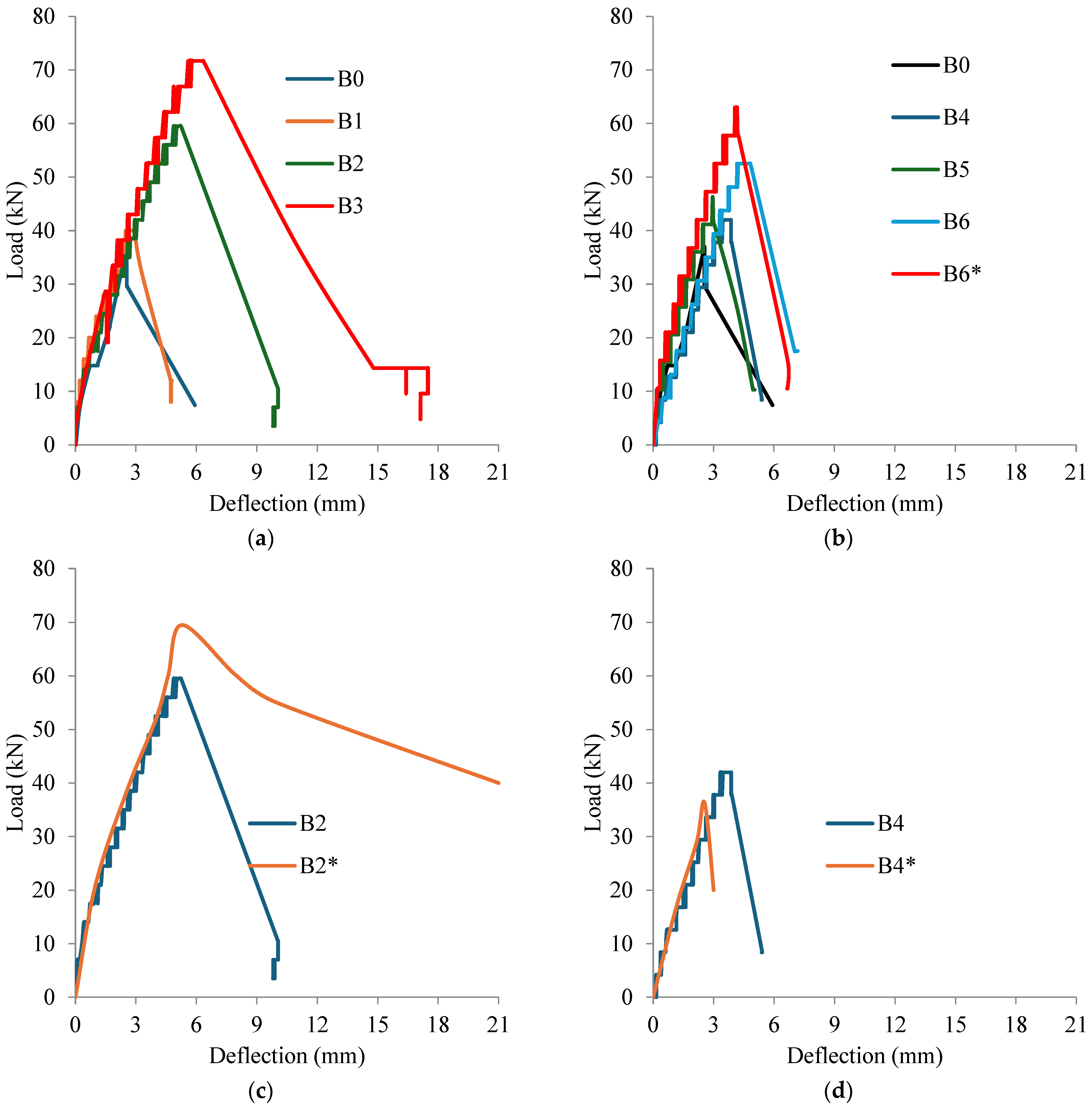
4.3. Load–Deflection Relationships

The load–mid-span deflection correlations for every tested beam are shown in Figure 7. Load–deflection curves may often be classified as having a bilinear connection. There are three sections to the curve: up to the cracking point, from the cracking point to the peak load, and from the peak load to failure. Since the concrete’s tensile strength mostly dictates this phase, the beam stiffness exhibited nearly identical patterns at low stress levels and up to the fractured load. When compared to control beam B0, it was shown that externally bonded steel wires at the splice site had a negligible impact on the stiffness, defined as the curve slope at the first stage of the spliced beams. However, the main result is a discernible rise in the curve’s peak for wire-reinforced beams made using different techniques. Additionally, following the peak, the curve’s slope declines, increasing the area under the curve—also referred to as the energy dissipation capacity (EDC). It was observed that the EDC of every wire-reinforced beam was higher than that of the control B0. Additionally, the use of externally bonded steel wires in the overlapping zone produced ductile behavior, evidenced by the load gradually decreasing after the tipping point. By postponing the splitting failure, wire confinement greatly improved the load–displacement response of the spliced beams. Also, evidently, B2* shows better ductile behavior than B3, even though B3 had nine longitudinal wires compared to six in B2*. The reason for this may be the conduction of U-shaped wires at the ends of the longitudinal wires in B2*. The peak of the curve of the beam B2* did not fall quickly due to the presence of a good bond at the ends of the longitudinal wires. This anchorage delays the process of wire separation, so the behavior of this beam B2* was better and gave a larger area under the curve compared to B3.

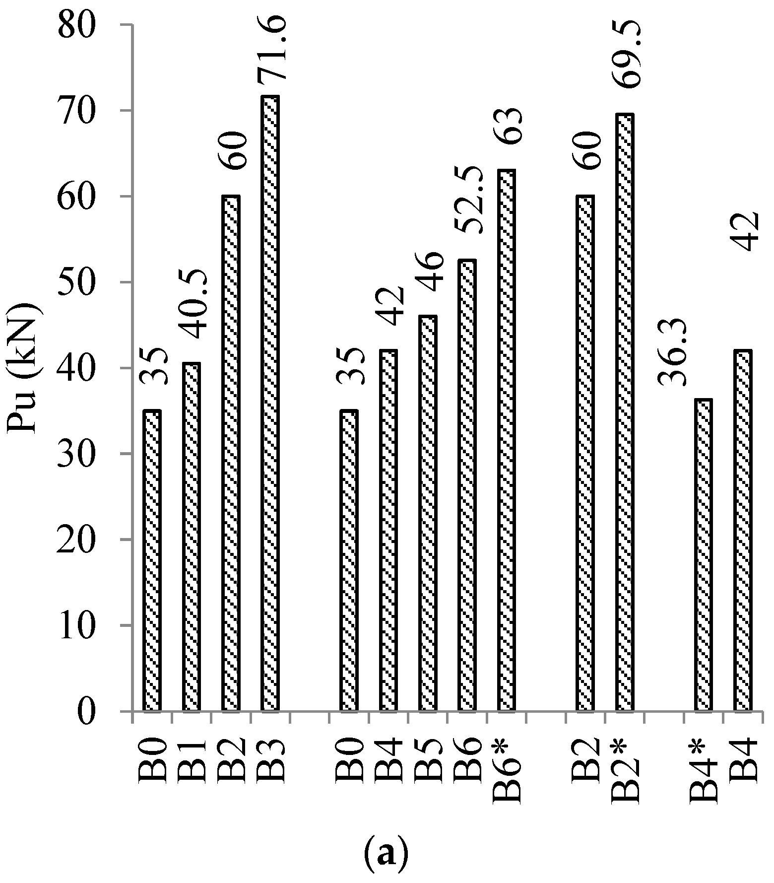
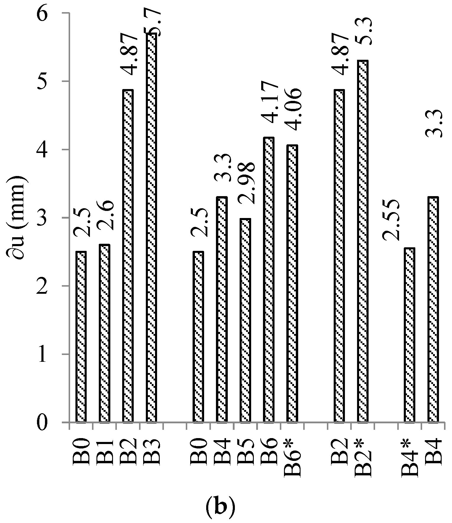
4.4. Ultimate Load and Corresponding Deflection

From the peak of the load–deflection curve, the maximum load (Pu) and the associated deflection (∂u) of each sample are presented in Table 1. The beams were divided into four groups to study several variables. Group GI studied the effect of the amount of longitudinal wires, while group GII assessed the effect of the amount of cross wires. The impact of performing end anchorage at the ends of longitudinal wires was examined in group GIII. The direction of the cross wires was studied in group GVI. It is clear from the results, in general, that all the methods implemented improved both the maximum load (Pu) and the deflection associated with it (∂u), as illustrated in Figure 8.
As indicated in Table 1, the use of longitudinal steel wires at the splice location increased the peak load (Pu) of spliced beams substantially. Conducting one, two, and three SWs and BWs in beams B1, B2, and B3 improved the Pu by 15.71, 71.43, and 104.57%, respectively. These improvements are due to the increase in reinforcement at the splice in the direction parallel to the lapped bars. This increased reinforcement contributed to bearing part of the tensile force resulting from the bending moment, which led to a decrease in the tensile force on the spliced bars. It is necessary to increase the load on the beam until the tensile force in the lapped bars reaches the collapse strength, which leads to an increase in the collapse load of the beam. Another positive aspect is the improvement in the deformation of the strengthened spliced beams, as well as in the Pu. Conducting one, two, and three SWs and BWs in beams B1, B2, and B3 improved the ∂u by 4%, 94%, and 128%, respectively. This indicates the success of the longitudinal wires in enhancing both load capacity and reducing deformation.
In order to generalize the results of this research, we must calculate the longitudinal wire reinforcement ratio using the following formula:
µ = N A w A l
N is the number of longitudinal wires (N = 3 in B1, 6 in B2, and 9 in B3). Aw is the cross-sectional area of one longitudinal wire (4.9 mm2). Al represents the cross-sectional area of lapped rebars (157 mm2).
The value of µ was 9.4 percent, 18.7 percent, and 28 percent in beams B1, B2, and B3, respectively. We can tell that when the longitudinal wire reinforcement-to-lapped rebars ratio was 9.4, 18.7, and 28%, the Pu of the beams was improved by 15.71, 71.43, and 104.57%, respectively, and the ∂u was enhanced by 4, 94, and 128%.
In group GII, the number of cross U-shaped wires achieved a clear enhancement in the maximum load (Pu) and associated deflection (∂u) of samples B4, B5, B6, and B6*. Conducting 4, 5, 6, and 12 UWs in beams B4, B5, B6, and B6* improved the Pu by 20%, 31.4%, 50%, and 80%, respectively, and increased the ∂u by 32%, 19%, 67%, and 63.4%, respectively. These wires, oriented transversely, provide enclosure of the concrete within the covering thickness area, which improves the cohesion resistance between the concrete and lapped rebars. When the cohesion resistance of concrete improves, the occurrence of collapse is delayed, which increases the maximum load of the beam (Pu). Therefore, the greater the percentage of wire enclosure, the greater the maximum load of the beam, which effectively facilitates the simultaneous improvement of both Pu and ∂u. In this study, it is advisable to implement a leg for the UWs extending by 100 mm on both beam sides to prevent the separation of wires at their ends. Also, making the wire slanted in the direction of the connection allows it to perform two roles. The first is to enclose an area larger than the link. The second bears part of the tensile force parallel to the splice.
In order to generalize the results of this section, we must calculate the transverse wire reinforcement ratio using the following equation:
ρ = A w N t β b · L
where Nt is the number of transverse wires. Aw is the cross-sectional area of one transverse wire (4.9 mm2). b is the beam width at the splice region. L is the length of the strengthening area at the splice region. β was set to 1 for a horizontal, inclined transverse wire used in beam B4*. The factor β of beams that are strengthened with inclined transverse wires (B4, B5, B6, and B6*) was estimated using the following equation:
β = sin + cos
where is the inclination angle between U-shaped transverse wires and the longitudinal axis of the beam (see Figure 3). Table 2 summarizes the results of the ρ for all beams strengthened with U-shaped transverse wires.
The relationships between the transverse wire reinforcement ratios (ρ) of the beams and the increasing ratios in Pu and ∂u are shown in Figure 9. It was noticed that as the ρ increased, the values of Pu and ∂u improved significantly. When the ρ ratio was 0.036, 0.051, 0.064, 0.075, and 0.150%, the Pu of the beams improved by 3.7, 20, 31.4, 50, and 80%, respectively, and the ∂u was enhanced by 2, 32, 19, 67, and 62.4%.
In group GIII, three cross U-shaped wires, placed perpendicular to the long wires, were used as an end tie. The implementation of an end tie in beam B2* achieved a slight enhancement of Pu (15.8%) and of ∂u (8.8%) compared to the similar beam B2 with no tie. This happened because there was a concrete splitting collapse at the ends of lapped bars in both the beams B2 and B2*.
In group GVI, the direction of UWs was studied. The number of UWs was four in both the beams B4 and B4*. B4 has italic UWs, while B4* has cross UWs. Performing UWs in B4 achieved an enhancement of the Pu (15.7%) and the ∂u (29.4%) compared to beam B4*. These enhancements happened because italic UWs caused confinement around the splice region and bear part of the tensile force in the direction parallel to the splice.
FRP confinement and NSM show great promise in comparison to other established methods for enhancing bond strength. The effects of the NSM approach with CFRP and steel bars were investigated on lap-spliced beams. According to certain research conducted by Allam [21], the flexural capacities of RC beams were enhanced by 73–91% when compared to lapped spliced beams and by 27–40% when compared to beam specimens without lapped rebars. The effectiveness of FRP in reducing bonding split collapse was investigated by Garcia et al. [22]. When comparing CFRP enclosure to unconfined samples, the bond quality and bar slip improved by up to 49% and 1200%, respectively. Strengthening techniques with one or two CFRP layers were very effective in enhancing the splice bond strength. Mousavi et al. [23] investigated NSM effects and the combination of NSM-CFRP confinement strengthening techniques on lap-spliced RC beams with low lap-splice length. The length of the NSM bar and the bottom concrete cover were factors to take into account, in addition to the need to improve the mechanism. According to the results, strengthening methods increase the ductility, capacity, and energy absorption capacity of lapping and spliced concrete beams.

5. Cost of the Presented NSM Strengthening

It is important to know the cost of the strengthening used in this program so that it can be compared to other methods. This project’s cost was determined by factoring in both labor and materials. The materials are first separated based on the wires’ weight and the quantity of epoxy used for installation. A total wire weight of 5 kg was used in all samples. Additionally, 3 kg of epoxy was utilized in total. Secondly, the cost of labor was determined as follows: in a single day, three workers cut all the grooves to install NSM wires before filling them in with epoxy. The cost of the current strengthening process (NSM) is displayed in Table 3. The entire cost came to 2350 Egyptian pounds (EGP), which is remarkably low when compared to other strengthening methods. This confirms that the use of this construction technique (NSM) is a cost-effective way to improve the quality and durability of RC components without many extra resources, which enhances value for money and reduces the risk of construction failure at the same time.

6. Conclusions

The aim of this paper was to examine the behavior of RC beams with inadequate lap splices enhanced by externally bonded NSM steel wires using various construction techniques to improve value for money and mitigate failure risk. Nine spliced beams were cast and strengthened using NSM procedures. In addition, one unstrengthened beam served as a reference. Two tension bars were joined in the middle of the beam using a splice length equal to 25 times the rebar’s diameter. To offer a pure bending range at the splice location, the four-point flexure experiment was used. The NSM wires had a 2.5 mm diameter. The tension rebar’s side and bottom coverings measured 23 mm, which equals 2.3 times the diameter of the lapped spliced bar, to prevent concrete splitting in the cover region. A variety of techniques were used to strengthen the splice region, including the installation of a network of intersecting and opposing wires in two different directions, the attachment of longitudinal wires to the sides and bottom of the beam, and the placing of perpendicular and inclined U-shaped wires at the splice region. End anchorage was optional during the attachment of longitudinal wires. Each sample was performed once in the work program. The effects of variables on the failure, cracking load, final load, ultimate deflection, and load–deflection response of strengthened beams were investigated. The results showed the following:
  • Most strengthened beams failed due to concrete splitting at the splice region accompanied by partial debonding at the wires–epoxy interface;
  • The cracking load of the three-longitudinal-wire beam was 60% more than that of the control beam;
  • When the longitudinal wire reinforcement-to-lapped rebars area ratio was 9.4%, 18.7%, and 28%, the ultimate load of the beams was improved by 15.71%, 71.43%, and 104.57%, respectively, and the ultimate deflection was enhanced by 4%, 94%, and 128% compared to the control beam;
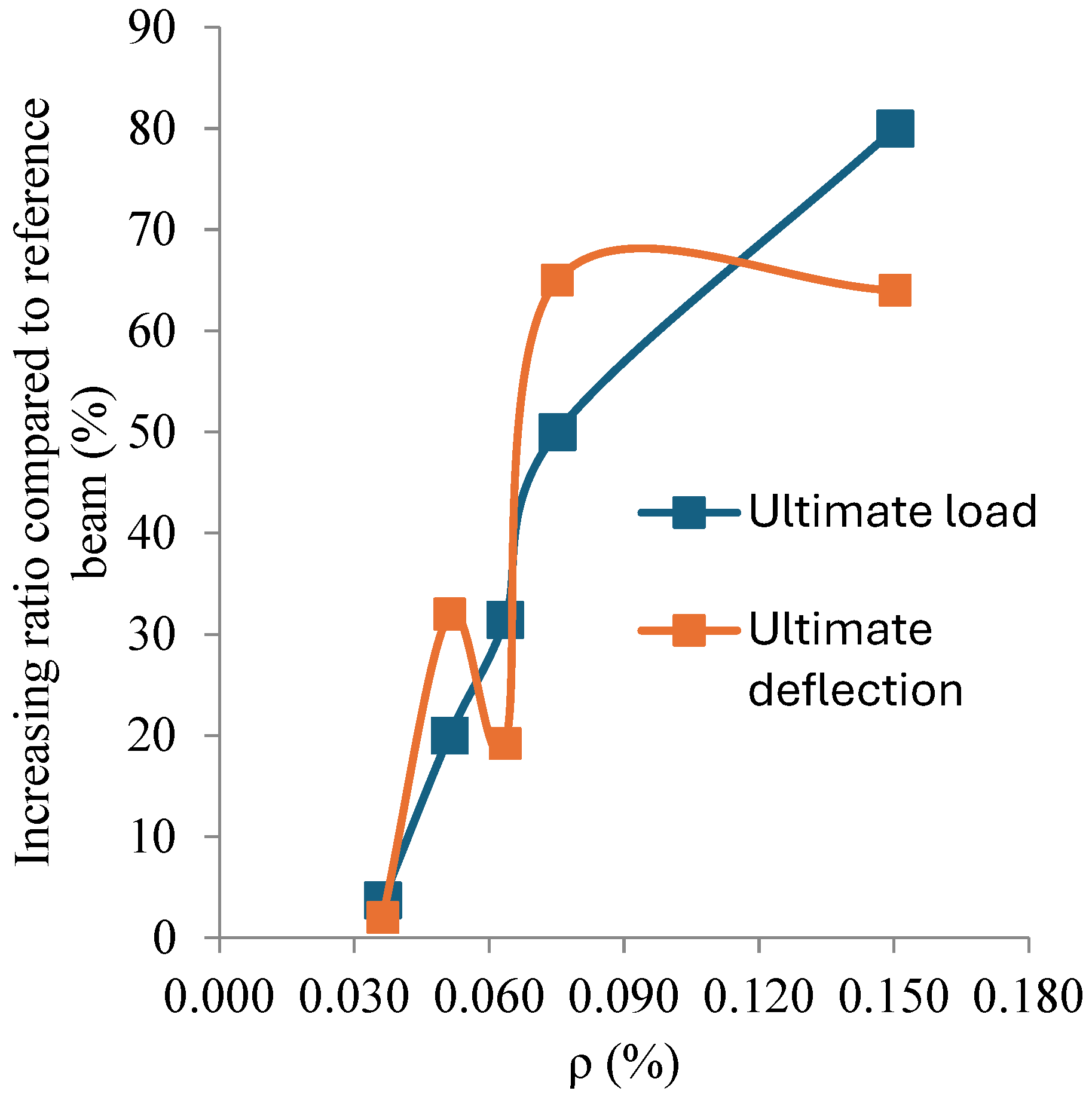
  • When the transverse U-shaped wire reinforcement ratio was 0.036%, 0.051%, 0.064%, 0.075%, and 0.150%, the ultimate load of the beams was improved by 3.7%, 20%, 31.4%, 50%, and 80%, respectively, and the ultimate deflection was enhanced by 2%, 32%, 19%, 67%, and 62.4% compared to the control beam;
  • When compared to a comparable beam without ties, adding end ties to the beam resulted in a minor improvement in the ultimate load (15.8%) and ultimate deflection (8.8%);
  • When compared to a comparable beam with perpendicular U-shaped wires, inclined U-shaped wires improved both the ultimate load (15.7%) and ultimate deflection (29.4%).

Author Contributions

S.F.: conceptualization, data curation, formal analysis, investigation, and writing—original draft. M.G.: methodology, formal analysis, and writing—review and editing. E.A.M.: methodology, validation, formal analysis, and writing—review and editing. R.W.B.: methodology, validation, formal Analysis, and writing—review and editing. E.M.: visualization, supervision, writing—review and editing and formal analysis. Y.O.Ö.: validation, supervision, and formal analysis, writing—review and editing. All authors have read and agreed to the published version of the manuscript.

Funding

This research received no external funding.

Institutional Review Board Statement

These tests were conducted at faculty of engineering, KafrElshiekh University, Egypt.

Data Availability Statement

The experimental data can be obtained through email communication with the corresponding author (Sabry Fayed).

Acknowledgments

The experimental tests were carried out by the reinforced concrete laboratory of the Faculty of Engineering, Kafer Elshiekh University, Egypt.

Conflicts of Interest

The authors declare no conflicts of interest.

References

  1. 408R-03; Bond and Development of Straight Reinforcing Bars in Tension (Reapproved 2012). American Concrete Institute: Farmington Hill, MI, USA, 2012.
  2. FIB. Model Code for Concrete Structures 2010, 1st ed.; Ernst & Sohn GmbH & Co.: Berlin, Germany, 2013. [Google Scholar]
  3. FIB. Bond and Anchorage of Embedded Reinforcement: Background to the FIB Model Code for Concrete Structures 2010; Bulletin No 72; FIB: Lausanne, Switzerland, 2014. [Google Scholar]
  4. Haavisto, J.; Alho, H.; Laaksonen, A. Behavior of lap splices in reinforced concrete beams after bar yielding. Struct. Concr. 2023, 24, 5245. [Google Scholar] [CrossRef]
  5. Ali, H.M.Y.; Sheikh, M.N.; Hadi, M.N.S. Flexural strengthening of RC beams with NSM-GFRP technique incorporating innovative anchoring system. Structures 2022, 38, 251–264. [Google Scholar] [CrossRef]
  6. Michels, J.; Sta’skiewicz, M.; Czaderski, C.; Lasek, K.; Kotynia, R.; Motavalli, M. Anchorage resistance of CFRP strips externally bonded to various cementitious substrates. Compos. Part B Eng. 2014, 63, 50–60. [Google Scholar] [CrossRef]
  7. Dias, S.J.E.; Barros, J.A.O.; Janwaen, W. Behavior of RC beams flexurally strengthened with NSM CFRP laminates. Compos. Struct. 2018, 201, 363–376. [Google Scholar] [CrossRef]
  8. Berardi, U.; Dembsey, N. Thermal and Fire Characteristics of FRP Composites for Architectural Applications. Polymers 2015, 7, 2276–2289. [Google Scholar] [CrossRef]
  9. ACI 440.2R-17; Guide for the Design and Construction of Externally Bonded FRP Systems for Strengthening Concrete Structures. American Concrete Institute: Farmington Hills, MI, USA, 2017.
  10. Zhang, S.S.; Yu, T.; Chen, G.M. Reinforced concrete beams strengthened in flexure with near-surface mounted (NSM) CFRP strips: Current Status and Research needs. Compos. Part B 2017, 131, 30–42. [Google Scholar] [CrossRef]
  11. Al-Saadi, N.T.K.; Mohammed, A.; Al-Mahaidi, R.; Sanjayan, J. A state-of-the-art review: Near surface mounted FRP composites for reinforced concrete structures. Constr. Build. Mater. 2019, 209, 748–769. [Google Scholar] [CrossRef]
  12. Siddika, A.; Al Mamun, M.D.A.; Ferdous, W.; Alyousef, R. Performances, challenges and opportunities in strengthening reinforced concrete structures by using FRPs—A state-of-the-art review. Eng. Fail. Anal. 2020, 111, 104480. [Google Scholar] [CrossRef]
  13. Lorenzis, L.D.; Teng, J.G. Near-surface Mounted FRP Reinforcement: An Emerging Technique for Strengthening Structures. Compos. Part B 2007, 38, 119–143. [Google Scholar] [CrossRef]
  14. Hassan, T.K.; Rizkalla, S.H. Bond mechanism of near surface mounted fiber reinforced polymer bars for flexural strengthening of concrete structures. ACI Struct. J. 2004, 6, 830–839. [Google Scholar]
  15. Fayed, S.; Ghalla, M.; Hu, J.W.; Mlybari, E.A.; Albogami, A.; Yehia, S.A. Shear strengthening of RC beams using prestressed near-surface mounted bars reducing the probability of construction failure risk. Materials 2024, 17, 5701. [Google Scholar] [CrossRef] [PubMed]
  16. Lv, J.B.; Lin, D.J.; Fu, B.; Liu, S.H.; Han, Z.J. Flexural performance of reinforced concrete beams strengthened using near-surface-mounted carbon-fiber-reinforced polymer bars: Effects of bonding patterns. Compos. Struct. 2024, 335, 117985. [Google Scholar] [CrossRef]
  17. Khol, S.; Seo, S.Y.; Van Tran, H.; Hanif, M.U. Shear Strengthening of RC Beams Using Partial-Length Near-Surface Mounted (PLNSM) CFRP Strips. Int. J. Concr. Struct. Mater. 2024, 18, 90. [Google Scholar] [CrossRef]
  18. Aljidda, O.; Alnahhal, W.; El Refai, A. Flexural strengthening of one-way reinforced concrete slabs using near surface-mounted BFRP bars. Eng. Struct. 2024, 303, 117507. [Google Scholar] [CrossRef]
  19. Saadah, M.; Ashteyat, A.; Murad, Y. Shear strengthening of RC beams using side near surface mounted CFRP ropes and strips. Structures 2021, 32, 380–390. [Google Scholar] [CrossRef]
  20. Abdel-Jaber, M.; Abdel-Jaber, M.; Katkhuda, H.; Shatarat, N.; El-Nimri, R. Influence of Compressive Strength of Concrete on Shear Strengthening of Reinforced Concrete Beams with Near Surface Mounted Carbon Fiber-Reinforced Polymer. Buildings 2021, 11, 563. [Google Scholar] [CrossRef]
  21. Allam, S.M. Flexural strengthening of RC beams with lap splices. Int. Rev. Civ. Eng. 2013, 4, 256–273. [Google Scholar]
  22. Garcia, R.; Guadagnini, M.; Pilakoutas, K.; Pech Poot, L.A. FRP strengthening of substandard lap-spliced RC members: A comprehensive survey. Adv. Struct. Eng. 2017, 20, 976–1001. [Google Scholar] [CrossRef]
  23. Mousavi, S.R.; Sohrabi, M.R.; Moodi, Y.; Gholamhosseini, E. Strengthening of Lap-Spliced RC Beams Using Near-Surface Mounting Method. Iran. J. Sci. Technol. Trans. Civ. Eng. 2022, 46, 251–259. [Google Scholar] [CrossRef]
Figure 1. Steel rods utilized. (a) 10 mm lapped spliced rebar in the beams. (b) NSM steel wires.
Buildings 15 00957 g001
Figure 2. Inner reinforcement and details of presented beams, dimensions in mm.
Buildings 15 00957 g002
Figure 3. Details of NSM schemes performed. (a) B1. (b) B2. (c) B3. (d) B2*. (e) B4. (f) B5. (g) B6. (h) B4*. (i) B6*.
Buildings 15 00957 g003aBuildings 15 00957 g003b
Figure 4. Some beams in the NSM method, bottom views. (a) Grooves of B2*. (b) Grooves of B6. (c) Grooves of B4*. (d) Opposite UWs inside grooves of B6*. (e) Filling grooves of B2. (f) Filling grooves of B4. (g) B4*. (h) B5.
Buildings 15 00957 g004
Figure 5. Failures of beams at the splice region, bottom views. (a) B0 with no wires. (b) B1 with one SW and one BW. (c) B2 with two SWs and two BWs. (d) B3 with three SWs and three BWs. (e) B2* with two SWs, two BWs, and three UWs. (f) B4 with four italic UWs. (g) B5 with five italic UWs. (h) B6 with six italic UWs. (i) B4* with four perpendicular UWs. (j) B6* with six opposite italic UWs. (k) Full image of failure mode.
Buildings 15 00957 g005aBuildings 15 00957 g005b
Figure 6. Cracking load of beams at the splice region.
Buildings 15 00957 g006
Figure 7. The load–mid-span deflection relationships for all tested beams. (a) GI. (b) GII. (c) GIII. (d) GVI.
Buildings 15 00957 g007
Figure 8. Results of ultimate load and corresponding deflection. (a) Pu. (b) ∂u.
Buildings 15 00957 g008aBuildings 15 00957 g008b
Figure 9. Effect of transverse wires ratio on ultimate load and deflection of the beams.
Buildings 15 00957 g009
Table 1. Results of ultimate load and corresponding deflection.
GroupParameterBeam IDPu (kN)Increase in Pu (%)∂u (mm)Increase in ∂u (%)
GIAmount of longitudinal wiresB0350.002.50.00
B140.515.712.64.00
B26071.434.8794.80
B371.6104.575.7128.00
GIIAmount of italic cross wiresB0350.002.50.00
B44220.003.332.00
B54631.432.9819.20
B652.550.004.1766.80
B6*6380.004.0662.40
GIIIEnd tieB2600.004.870.00
B2*69.515.835.38.83
GVIDirection of cross wiresB4*36.30.002.550.00
B44215.703.329.41
Table 2. Values of transverse wire reinforcement ratio of the beams.
Beam Aw
(mm2)
L (mm)b
(mm)
Nt βρ (%)
B4*4.94501204N/A10.036
B44.94501204521.410.051
B54.94501205591.40.064
B64.94501206641.380.075
B6*4.945012012641.380.150
Table 3. Cost of the current strengthening procedure (NSM).
Item Wires Epoxy LaborTotal Cost
Amount 5 kg3 kg3 people
Cost 250 EGP1200 EGP900 EGP2350 EGP
Disclaimer/Publisher’s Note: The statements, opinions and data contained in all publications are solely those of the individual author(s) and contributor(s) and not of MDPI and/or the editor(s). MDPI and/or the editor(s) disclaim responsibility for any injury to people or property resulting from any ideas, methods, instructions or products referred to in the content.

