Abstract
As foundation pit engineering is developing towards larger and deeper designs, the requirements for controlling excavation-induced deformation are becoming increasingly stringent, particularly in complex urban environments and soft soil areas. In recent years, numerous foundation pit projects have incorporated Hydraulic Servo Steel Support (HSSS) to actively manage the axial forces of the internal supports, which has achieved significant reductions in the displacement of the retaining structures (δD). An investigation of engineering cases in soft soil areas revealed that the average ratios of the δD to the excavation depth (H) for foundation pits with and without servo control systems were 0.11% and 0.38%, respectively. This study analyzed the monitoring data related to the δD, the deformation of the soil outside the foundation pit, and the changes in the axial force of the internal supports in a deep foundation pit located in Hangzhou City, China. The results indicated that employing the zoned excavation and HSSS effectively controlled the δD. During the excavation stage, the HSSS ensured that the δD remained below the design threshold, although some deformation persisted during the dismantling stage. Additionally, adjustments to the axial force of the internal supports affected the axial force of the adjacent supports, with a common occurrence of reverse pulling force in the first-layer supports due to the action of the HSSS. Therefore, further optimization of the HSSS is necessary to enhance control effectiveness.
1. Introduction
With the ongoing advancement of urbanization, there is an increasing demand for infrastructure, including underground rail transit, commercial complexes, and parking facilities. To maximize spatial efficiency, foundation pit projects are evolving towards larger and deeper designs.
Concurrently, the complexities associated with foundation pit engineering necessitate the continuous development of corresponding construction technologies and methodologies [1]. Conventional techniques have progressed from simple retaining piles and diaphragm walls to more sophisticated approaches that combine retaining structures with prestressed anchor cables and concrete cables, ultimately leading to complex support systems incorporating various prestressed steel supports. Additionally, construction strategies have evolved from basic, one-time dewatering and excavation to more refined management practices, such as stratified dewatering, recharge dewatering, and zoned excavation [2,3,4,5]. While these advancements have successfully managed many foundation pit projects, traditional methods often struggle to address the specific challenges posed by soft soils, which are characterized by high water content, high compressibility, and low strength. These conditions can lead to significant deformation during deep foundation pit excavation, thereby affecting the safety of surrounding buildings and underground facilities, as well as the overall stability of the foundation pit. Consequently, numerous recent projects have integrated Hydraulic Servo Steel Support (HSSS) into deep foundation pit engineering, yielding favorable outcomes. The HSSS is a real-time compensation and monitoring system for steel support axial force. The system continuously monitors the support axial force around the clock and adjusts the support axial force in a timely manner based on the parameters measured using high-precision sensors. It actively controls the deformation of the retaining structure by managing the axial force of the jack. Therefore, selecting appropriate support methods and implementing effective technical measures are crucial for ensuring the safety of foundation pit engineering [6,7,8,9].
After excavation in soft soil areas, the retaining wall exhibits significant creep deformation, making it difficult for concrete supports to meet the deformation requirements of the retaining structure. Traditional prestressed steel supports also experience substantial prestress loss. In recent years, numerous scholars [10,11,12,13,14,15] have conducted research on deep foundation pit engineering using HSSS across various regions. Analyses of field monitoring data confirmed the feasibility and advanced nature of these systems under soft soil conditions [16,17,18,19,20,21,22].
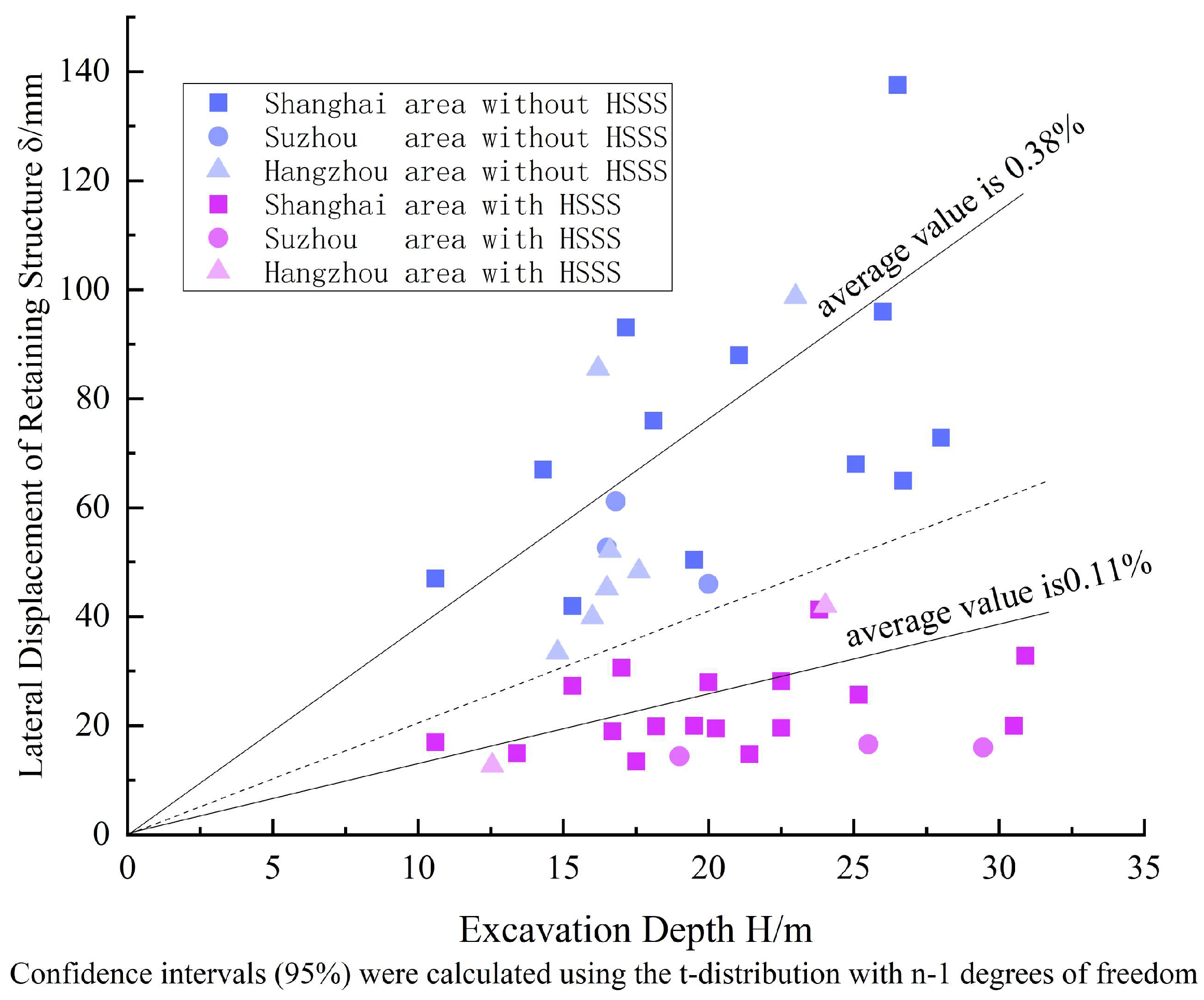
This study performed a statistical analysis of projects utilizing steel support [23] by collecting data from a total of 48 foundation pit projects located in soft soil areas, including Shanghai, Suzhou, and Hangzhou. These projects primarily comprised subway foundation pits and residential construction foundation pits. The research focused on the displacement of the retaining structure (δD) during foundation pit excavation under both prestressed steel support systems and HSSS. Figure 1 illustrates the excavation depth (H) and the corresponding δD for various projects, where the slope of the line represents the ratio of the δD to the H of the foundation pit. For foundation pits without HSSS, horizontal δD ranged from 0.23%H to 0.78%H (mean = 0.38%H, 95% CI = 0.30–0.44%H), demonstrating both elevated deformation rates and substantial data variability. For foundation pits with HSSS, horizontal δD ranged from 0.05 to 0.18%H (mean = 0.11%H, 95% CI = 0.09–0.13%H), demonstrating a 71% deformation reduction versus non-HSSS cases and minimal data dispersion. Notably, the slope of the blue points consistently exceeded that of the red points, indicating effective δD control when employing the HSSS.
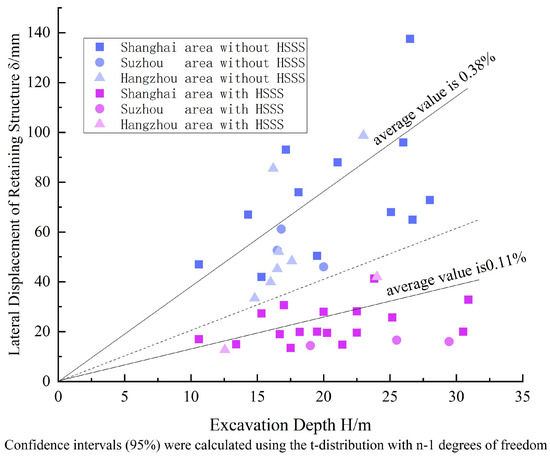
Figure 1.
Retaining structure and maximum deformation. Confidence intervals (95%) were calculated using the t-distribution with n-1 degrees of freedom.
Numerous researchers conducted theoretical analyses of the deformation responses of retaining structures in foundation pits utilizing servo internal support techniques. Huang et al. and Li et al. [24,25,26] investigated the δD using the elastic foundation beam method and a mixed boundary condition that treated the internal servo support as a “concentrated force + spring element”. They re-established the force equilibrium equation for diaphragm walls and performed iterative calculations to validate their approach. However, further investigation is warranted regarding the selection of specific parameters for mixed boundary conditions of the HSSS. Xu et al., Ding et al., and Feng et al. [27,28,29,30] applied the energy method to optimize the deformation calculations for supported foundation pits, based on the principle of minimum potential energy, to predict the impact of foundation pit excavation on surrounding structures.
Additionally, some scholars have employed simulation tests to study foundation pits with servo internal supports. Di et al. [31] explored the adjustment processes of the HSSS through model tests and analyzed the interaction between the axial force of the internal supports and their lengths. Based on model tests, Chen et al. [32] investigated the effects of varying lengths of servo internal support on the mechanical changes and deformation characteristics of the internal supports, retaining structures, and soil. Nonetheless, experimental research often focuses on specific working conditions or variables, which limits the applicability of the findings and makes it challenging to comprehensively address all influencing factors in complex engineering scenarios. Thus, integrating final experimental results with theoretical studies is essential.
Some scholars have also focused on optimizing foundation pit engineering from design and application perspectives. Xu et al., Fan et al., and Lin et al. [33,34,35] achieved more accurate deformation calculations by examining the relationship between the earth pressure and the δD. Chen et al., Huang et al., Tang et al., and Sun et al. [36,37,38,39] optimized the layout of supports, construction processes, and prestress levels for foundation pits incorporating HSSS and verified the efficiency and safety of these systems in reducing the δD. Cao et al. [40] implemented a “dual control” method to conduct an in-depth analysis of the application of the HSSS.
Given the engineering characteristics of soft soils in Hangzhou, traditional support methods often fail to achieve optimal results, making the exploration of novel support technologies particularly significant. Existing literature primarily focuses on technical feasibility, with less attention given to the changes in the support system of foundation pits in soft soil layers throughout their entire life cycle. This paper quantitatively supplements the control effects of using HSSS in foundation pits through statistical analysis of multiple engineering cases. Additionally, it extends the understanding of the variation patterns of HSSS throughout its entire life cycle in soft soil areas by observing and analyzing a deep foundation pit project in Hangzhou. The current study is structured as follows: Section 1 introduces the fundamental principle and application status of the Hydraulic servo steel supports. Section 2 describes the monitoring schemes and methods. Section 3 analyzes the monitored data and evaluates the performance of the HSSS. Section 4 presents design and construction recommendations for deep foundation pits in soft soils in Hangzhou City.
2. Project Background and Monitoring Plan
2.1. Project Background
The project is located in the core area of WangJiang New Town, ShangCheng District, Hangzhou City. The southwestern boundary is adjacent to the operational section tunnel between ChengCheng Station and WuJiang Road Station on Line 1. According to the relevant management regulations of Hangzhou City, the areas within 50 m of the structural profile of the main body of the subway station and tunnel sections, as well as the areas within 20 m of the structural profile of ancillary structures and other facilities, are designated as control protection zones for the subway. Consequently, the deformation requirements for the retaining structures in the foundation pit project are very stringent.
The subway tunnel is located on the west side of the foundation pit, with a vertical distance of 17 m. The tunnel is buried below the nearest excavation surface of the foundation pit. To avoid excessive construction loads, the project department has been set up in the foundation pit and tunnel area, and a large open space has been reserved to prohibit vehicle traffic, ensuring minimal disturbance to the foundation pit and tunnel.
The specific partition numbers, excavation depth, and support structure are shown in Table 1. For Plot 4#, which is generally triangular, the aim is to minimize the impact on the subway tunnel and to the greatest extent control the deformation of the retaining structure. The foundation pit was subdivided into 12 smaller pits using the partition jumping excavation method. Since pit 2A11 is located outside the subway control protection zone, three concrete supports were adopted. Since the other pits are situated within the control protection zone, the first layer of these pits adopted concrete supports, while the second to fourth layers employed HSSS. On the south side of the underground two-layer pits, an 800 mm thick diaphragm wall was used, with a buried depth ranging from 26.0 m to 29.5 m. On the outer side, a 700 mm thick TRD was utilized for groove wall reinforcement and served as a waterproof curtain. On the inner side, triaxial cement mixing piles with a diameter of 850 mm were employed for groove wall reinforcement. Additionally, MJS construction piles were implemented to reinforce the water stop zones at the junction of the diaphragm wall and the drilled piles.

Table 1.
Batch numbers and support structure.
2.2. Geological and Hydrogeological Conditions of the Site
The strata within the excavation depth range can be divided into 10 engineering geological layers and 20 engineering geological sub-layers. From top to bottom, they are: (1) mixed fill, (2) sandy silt, (3) silt, (4) silty clay, (5) silty clay, (6) silty silt clay, (7) boulder, (8) pebble, (9) strongly weathered tuff, and (10) medium-weathered tuff. Detailed soil layer parameters are shown in Table 2.
Table 2.
Parameters of each stratum.
The groundwater in the site is primarily distributed in three layers: the upper layer is pore diving water, the middle layer is confined water, and the lower layer is the original water from the bedrock fissures beneath the foundation pit base, which has little impact on the project.
2.3. Excavation Scheme and Monitoring Plan
2.3.1. Excavation Scheme
The area where the first-layer concrete supports are located was first excavated to the design elevation of the crown beam on the surface of the foundation pit. Once the strength reached the design strength, excavation proceeded sequentially from top to bottom. When excavating to the bottom of each layer of supports, the steel supports were installed and the servo prestress was applied. This alternating process of excavation and support was repeated until the excavation reached the foundation pit bottom slab. After the bottom slab was poured, the construction of the main structure began. If the steel supports were above the middle slab, the middle slab was poured first; otherwise, the steel supports were removed first and then the middle slab was poured.The typical cross-section of the foundation pit is shown in Figure 2.
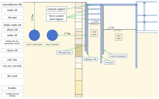
Figure 2.
Typical cross-section of the foundation pit.
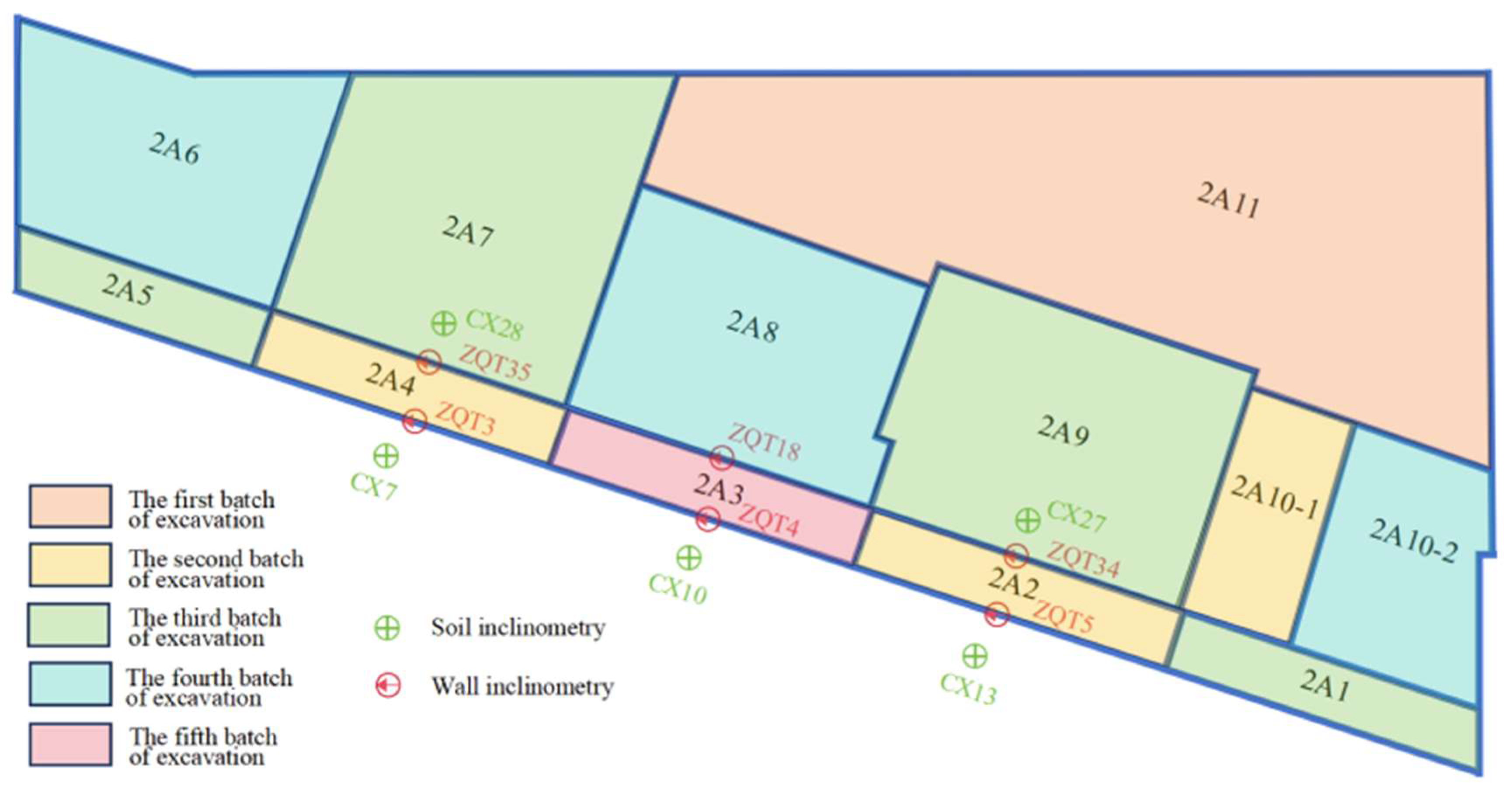
The zoning map of Plot 4# is shown in Figure 3. The foundation pit excavation adhered to the jumping pit method. Excavation began with pit 2A11, followed by pits 2A2, 2A4, and 2A10-1, which are located near the subway. The drainage pits 2A7 and 2A9, as well as the pits 2A1 and 2A5 adjacent to the subway, were also excavated. Subsequently, the remaining pits 2A6, 2A8, and 2A10-2 within the central drainage area were excavated. Finally, pit 2A3 near the subway was excavated. For the 4# Plot, this study focused on a comparative analysis of two different working conditions across three small excavation pits, 2A2, 2A3, and 2A4, all of which are located near the subway. Pits 2A2 and 2A4 were excavated first and surrounded by undisturbed soil, whereas pit 2A3 was the last to be excavated. Since the main structure of the basement had already been constructed on the north and east sides of the foundation pit, only the soil on the south side, near the subway, remained unexcavated.
Figure 3.
Zoning map of Plot 4#.
2.3.2. Monitoring Plan
A large amount of scientific monitoring was conducted during the excavation process of this project’s foundation pit. All monitoring data was sourced from a third-party monitoring unit not involved in the construction. Monitoring was carried out daily in accordance with relevant monitoring standards and using calibrated equipment. This study primarily focused on the retaining structure of small foundation pits 2A2, 2A3, and 2A4, the deep displacement of the soil behind them, and the changes in the axial force of the internal support. Particular emphasis was placed on the horizontal displacement and axial force variations of the retaining structures under different excavation conditions. The distribution of monitoring points is illustrated in Figure 4.
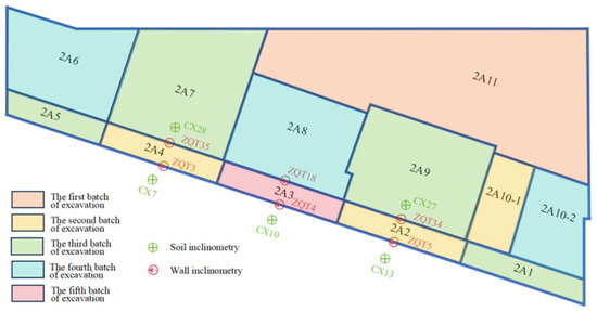
Figure 4.
Layout of monitoring points.
3. Results and Analysis
3.1. Horizontal Displacement of the Retaining Structure
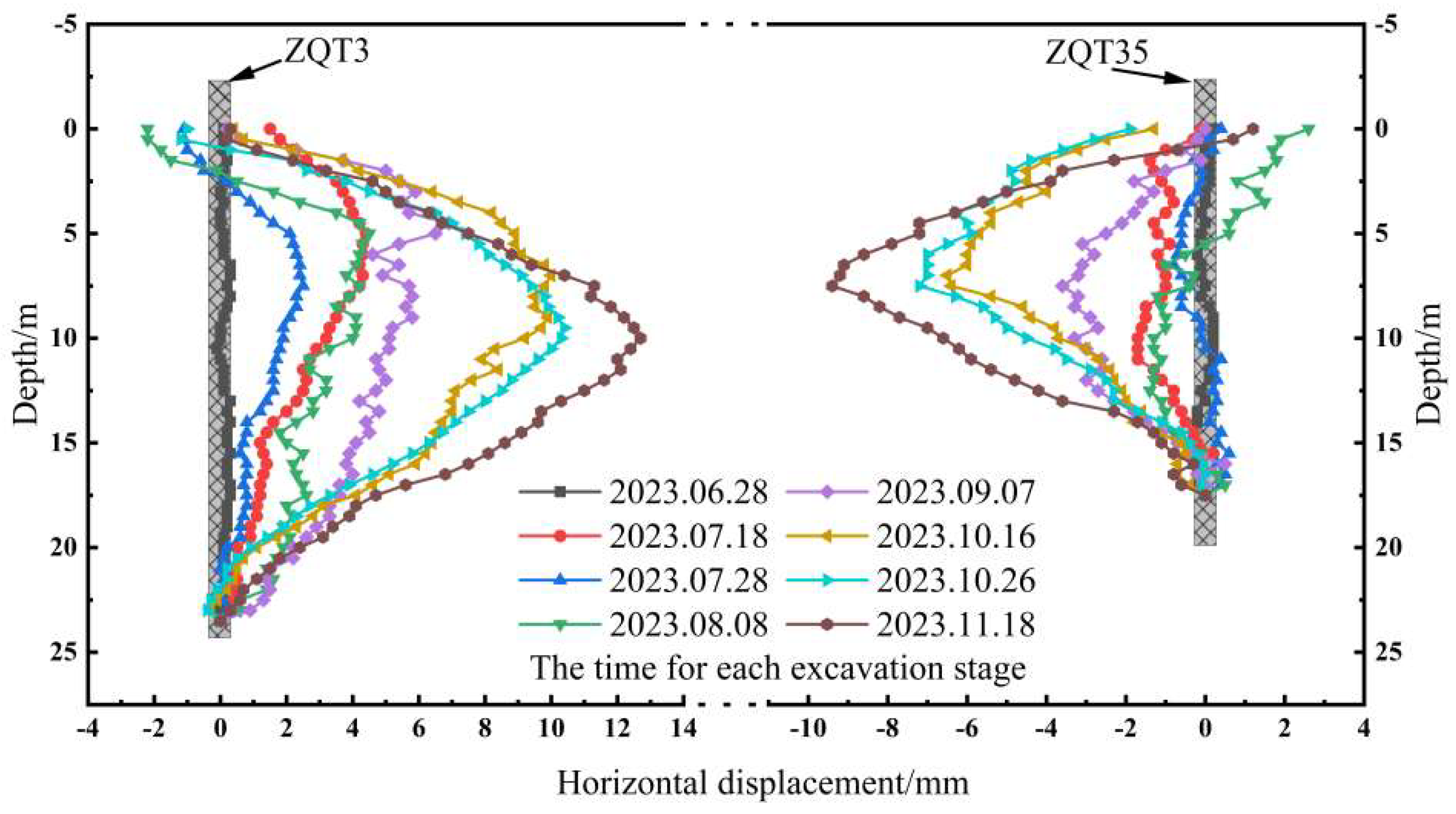
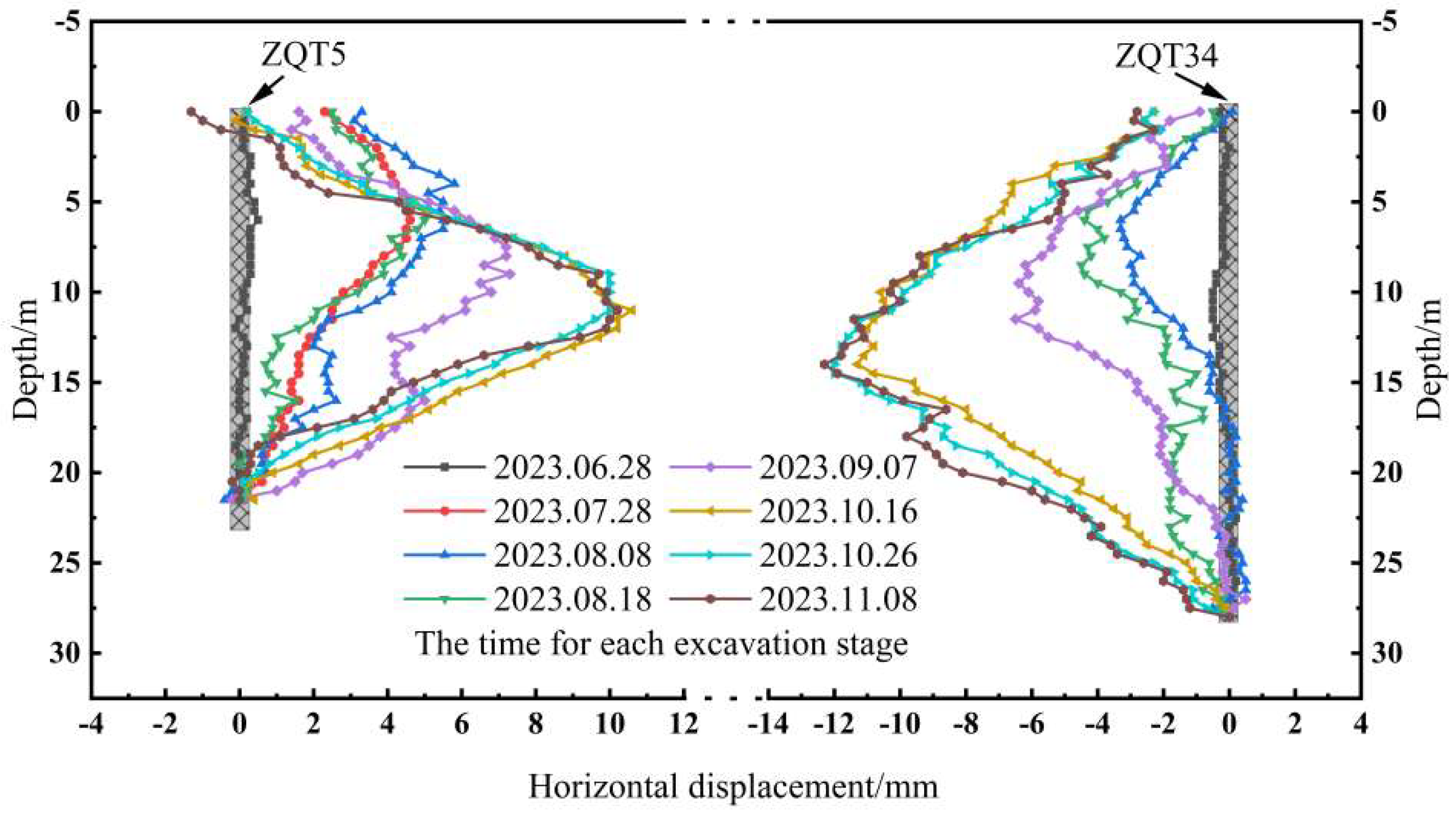
Pits 2A4 and 2A2 exhibited similar working conditions, with soil present on both sides during excavation. Monitoring status of foundation pit in zone 2A2 and 2A4 is shown in Figure 5 and Figure 6. ZQT3 and ZQT35 are the deformation curves of the retaining structure of pit 2A4, where the ZQT3 is near the subway side and the ZQT35 is far from the subway side. ZQT5 and ZQT34 are the deformation curves of the retaining structure of the pit 2A2, where the ZQT5 is near the subway side and the ZQT34 is far from the subway side. The excavation began on 28 June 2023, followed by the pouring of the bottom slab on 5 September 2023. Subsequently, the supports were systematically removed from bottom to top to facilitate the construction of the main structure and the gradual removal of the internal supports.

Figure 5.
Monitoring the status of the foundation pit in zone 2A2.
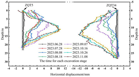
Figure 6.
Monitoring the status of the foundation pit in Zone 2A4.
During the excavation process, the retaining structures on both sides of the foundation pit exhibited a bulging deformation pattern. The maximum δD occurred near the bottom of the foundation pit. As the excavation progressed, the δD increased, with the maximum displacement ranging from 4 mm to 8 mm. This observation demonstrated the effectiveness of the HSSS in controlling the δD. The topmost partition of the retaining structure tended to deform towards the outside of the foundation pit, which was attributed to the active axial force exerted by the HSSS. The outward thrust caused deformation at the top partition, while the internal steel bars were anchored to the crown beam to prevent the first-layer supports from detaching.
After excavating to the bottom of the foundation pit, the building’s slab was constructed, followed by the pouring of the replacement slab. The replacement slab was then constructed and removed layer by layer. Monitoring data indicated that even after the removal of the HSSS, the retaining structure continued to deform, with a maximum deformation increment of 6 mm. This could be attributed to two reasons: ① The position of the support plates generally coincides with the location of the main structure layers, which often have larger intervals compared to the internal supports, resulting in smaller stress equilibrium points for the retaining structure and, thus, greater deformation. ② In the design calculations, the stiffness of the main structure is typically assumed to be infinite. However, during construction, the retaining structure, support plate, and main structure cannot form a symmetric force, leading to deformation in the retaining structure under passive pressure. This also indirectly demonstrates that the active control of axial force can effectively mitigate the δD.
The displacement of the retaining structure continues to increase throughout the entire phase, which is not only related to the excavation conditions but also possibly to the properties of the soft soil. The high sensitivity of the soft soil causes it to be disturbed after the deformation of the excavation retaining system. Additionally, the repeated application of axial force via the HSSS creates continuous disturbance to the soft soil, leading to structural damage, redistribution of internal forces, and an enhanced effect of lateral earth pressure, thereby increasing the stress on the retaining piles.
These observations indicated that: ① the HSSS effectively controlled the δD; and ② the potential δD during dismantling should be thoroughly considered during the design stage.
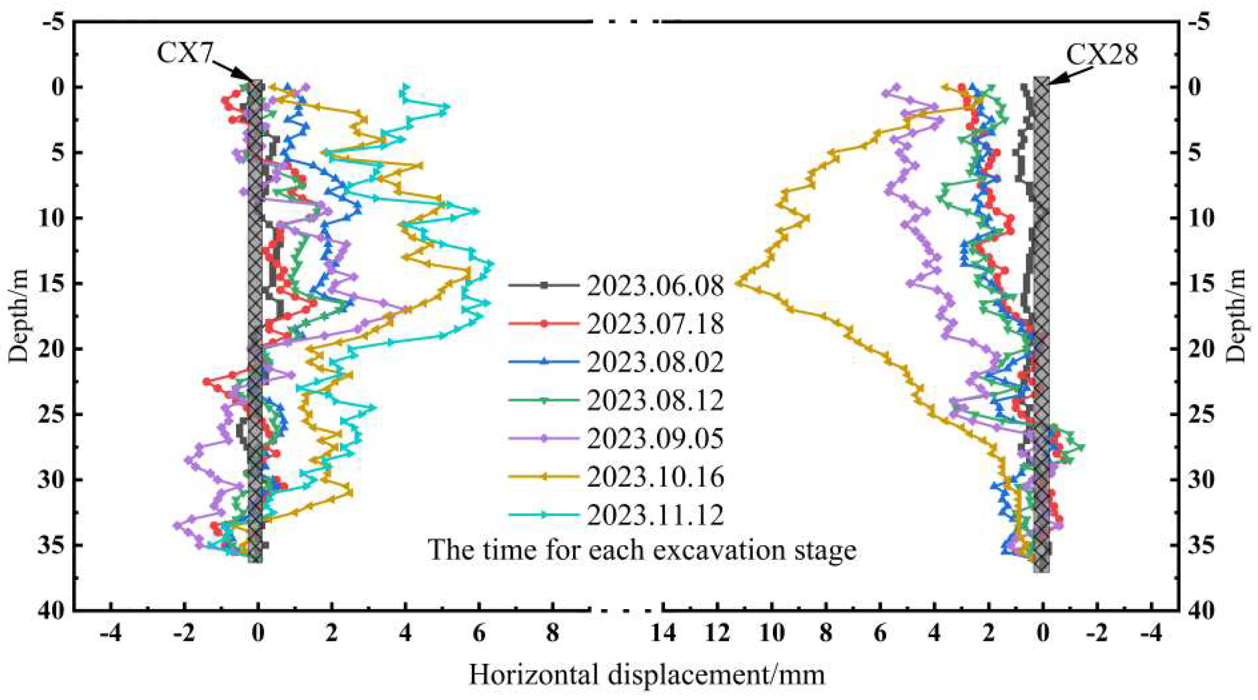
3.2. Horizontal Displacement of Soil
Figure 7 and Figure 8 illustrate the deformation of the soil outside the foundation pit retaining structure, where CX13 is outside ZQT5, while CX27 is outside ZQT34. A comparison revealed that, as the excavation progressed, the soil on both sides of the foundation pit exhibited a tendency to deform inward. The maximum displacements of the soil and retaining structure are listed in Table 3 and Table 4.

Figure 7.
Deformation diagram of soil outside the retaining structure of foundation pit 2A2.
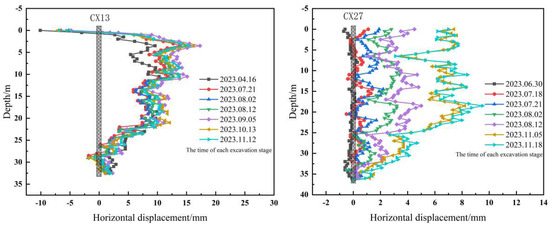
Figure 8.
Deformation diagram of soil outside the retaining structure of foundation pit 2A4.
Table 3.
Maximum displacement of soil and retaining structure in foundation pit 2A2.
Table 4.
Maximum displacement of soil and retaining structure in foundation pit 2A4.
Deformation diagram of soil outside the retaining structure of foundation pit 2A2 and 2A4 are shown in Figure 7 and Figure 8. A comparison of the maximum displacements between the soil behind the retaining wall and the adjacent retaining structures indicated that the displacement of the soil was generally consistent with that of the retaining structure; however, the displacement of the soil demonstrated a degree of variability. This variability may arise from the discrete deformation pattern of the soil outside the retaining structure, which was influenced by the construction roads surrounding the foundation pit and the temporary piling.
Therefore, the monitoring of the foundation pit should primarily focus on the lateral δD, while the settlement of the soil should be the main concern.
The deformation of the soil continues to expand after excavation to the bottom of the foundation pit, which may mainly be due to the disturbance of the soft soil layer and the repeated application of stress caused by changes in the axial force of the support, resulting in significant creep phenomenon in the soil. From this, we can see that the monitoring of the foundation pit should mainly focus on the lateral deformation of the retaining structure, and the soil should be monitored primarily for settlement. Therefore, in soft soil foundation pit areas, soil monitoring in the direction perpendicular to the retaining structure of the foundation pit should be strengthened.
3.3. Axial Force of the Support Structure
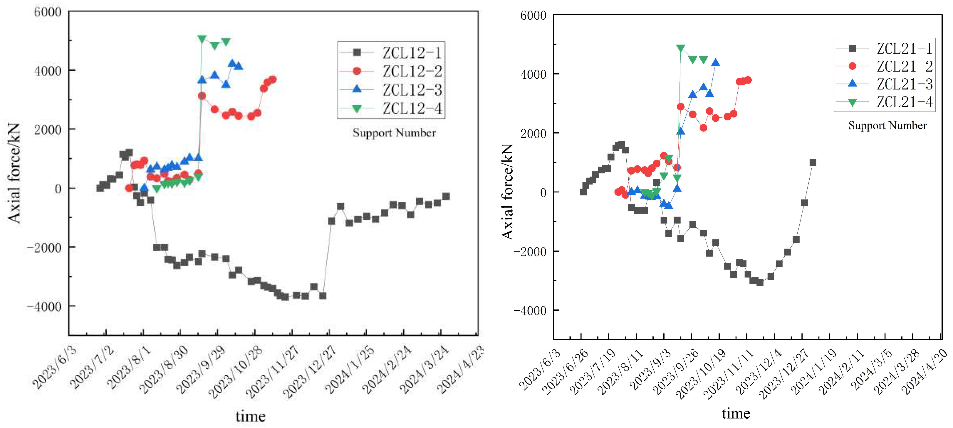
Figure 9 illustrates the variation in the axial force of the concrete supports in pits 2A4 and 2A2, where the ZCL12 denotes the monitoring point at the concrete support No. 12, while “1” to “4” indicate the concrete supports on the first to the fourth layers. It can be observed that after the completion of the first-layer concrete supports, the internal force of the support increased linearly with the depth. Following the installation and pressurization of the second-layer HSSS, the axial force of the first-layer supports significantly decreased, transitioning from a compressive to a tensile state. Due to the riveted connection between the concrete support and the crown beam, the first layer of support did not detach during the tension process. After the pressurization of the second- and third-layer HSSS, the stress in the first-layer supports showed continuous changes. Additionally, it was observed that the axial force of the second-layer supports demonstrated a decreasing trend after the pressurization of the third-layer supports, and the axial force of the third-layer supports similarly decreased after the pressurization of the fourth-layer supports. This indicated that the axial forces of the supports were interdependent, as consistent with the research by Cao Xueshan, Huang Biao, Yu Qinqin, and Huang Yanjun [41,42,43,44]. The retaining pile is assumed to be an elastic foundation beam, and the axial force is equivalently treated as a spring or force. The incremental method is used for research, and the force received by the internal support will change with the variation of the axial force of adjacent supports.
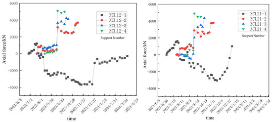
Figure 9.
Curve of variation in the supports’ axial force.
With the removal of the fourth-layer supports, the axial force of the third-layer supports increased and stabilized. Similarly, after the second- and third-layer supports were removed, the axial force of the second- and first-layer supports increased significantly and then stabilized. This phenomenon further confirms that the axial forces of the supports are consistent within the vertical plane, and the phased impact is primarily related to the nearest support layer. Finally, when all the HSSS from the second to the fourth layers were removed, the axial force of the first-layer concrete supports shifted from a tension state to a compression state. This finding resembles that observed in the traditional concrete internal support system.
The HSSS dynamically adjusts the axial force and displacement during the construction process to respond to changes in earth pressure. These controls play an important role in mitigating axial force fluctuations and local overload or unloading. The variation pattern of the axial force indicated in this case was closely related to the adjustment effect of the HSSS. During the excavation stage of the pit bottom, the HSSS could effectively control the δD by adjusting the axial force of the supports. During the stage of bottom-up removal of the supports, the HSSS could effectively maintain the axial force of the internal supports and the displacements to ensure the overall stability of the foundation pit.
4. Discussion
4.1. Effectiveness of the HSSS
During the project design stage, the maximum horizontal δD was expected to be no more than 10 mm based on the geological survey and construction plan. The monitoring data indicated that the maximum δD was 6 mm during the period from excavation to the bottom slab at a depth of 12.55 m, while it was 12 mm during the period from demolition to backfilling. These outcomes demonstrated that the deformation control capability of the HSSS exceeded the design expectations in practical applications.
4.1.1. Prestressing Application Scheme
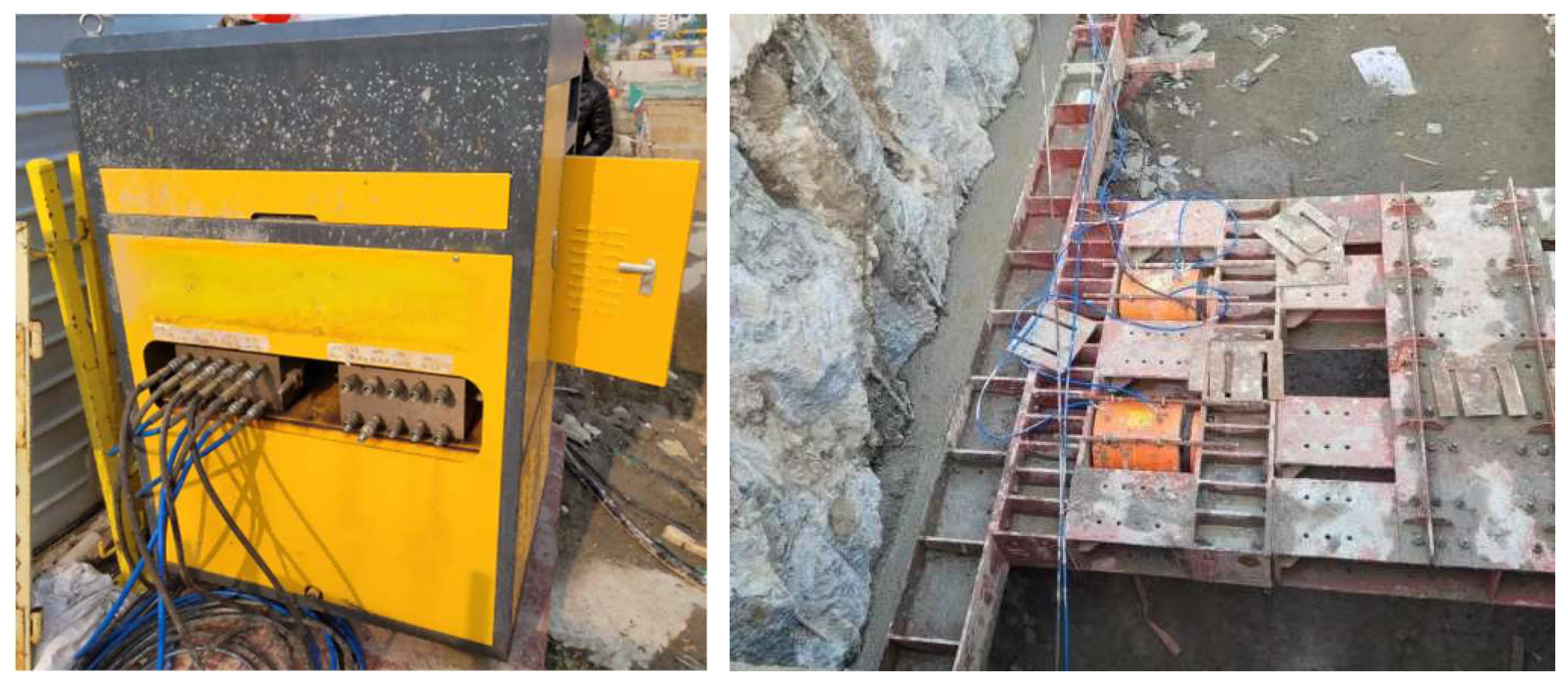
This project employed the HSSS, which consists of an on-site electro-hydraulic servo cylinder and a steel support end jack. The on-site photos are presented in Figure 10. The distribution and loading modes of the HSSS for pits 2A2, 2A4, and 2A3 are summarized in Table 5.

Figure 10.
Field equipment diagram.
Table 5.
Servo system axial force adjustment range.
Taking the 2A2 area as an example, the axial force adjustment range of the specific servo system is calculated by the design unit’s software in accordance with the echnical Code for Building Foundation Excavation Engineering in Zhejiang Province [45] and historical projects in Zhejiang. The alarm axial force values for the second, third, and fourth supports are rounded to 1.2 times the design calculation value Nk. The initial force application is rounded to 0.8 times the calculated axial force value Nk. The lower adjustment limit is a reduction of 100 kN per jack, and the upper adjustment limit is 0.88 times the alarm value.
The adjustment range of the axial force for each support servo system is shown in Table 5. The initial additional force of the steel support represents the application of the initial prestress. When the monitored axial force of the steel support falls below the lower limit of the adjustment range, the axial force of the servo cylinder is increased by extending the pressurized jack cylinder; otherwise, the servo cylinder depressurizes, the jack cylinder retracts, and the axial force is reduced to meet the control upper limit. If the jack cylinder fully retracts, the servo cylinder loses its adjustment function, and the axial force continues to increase to the corresponding alarm axial force, triggering an alarm in the servo system. If the jack cylinder exceeds its maximum stroke, the servo axial force cannot reach the set value, also triggering an alarm in the servo system.
4.1.2. Effectiveness of the Hydraulic Servo Steel Supports
The variation of axial force indicated that the installation of the hydraulic servo steel supports can effectively stabilize the axial force, and no prestress loss was observed in the prestressed steel supports.
After the axial force was applied to the support, the axial force of the adjacent supports would be affected and changed accordingly. The changed axial force values were within the range set by the HSSS, allowing the servo jack cylinder to adjust accordingly rather than being fixed.
As the lower steel supports were dismantled and the HSSS intervened, the axial force of adjacent upper supports and the tensile force in concrete gradually increased, while the deformation of the retaining structure also developed. At this time, the HSSS actively participated in dynamic adjustments, using axial force as the control target and displacement as the adjustment means, thereby ensuring the overall stability of the support system.
It is worth considering that soft soil exhibits significant creep characteristics, and the axial force of the internal support in the foundation pit continues to increase even without excavation. To achieve the goal of controlling displacement, it may be necessary to actively increase the axial force of the servo jacks. Additionally, in areas with thick soft soil, due to the force exerted by the servo jacks, the soil undergoes deformation, leading to a redistribution of loads, which results in a certain deviation between the axial force and the design value.
For overall consideration, the adoption of HSSS effectively ensures the safety of foundation pit excavation and the deformation of the tunnel within the corresponding range; the use of active load adjustment fully utilizes the axial force of steel supports, which can better save costs. The observation results are consistent with the statistical results, and the horizontal displacement of the retaining structure of the foundation pit is δwh = 0.135%H.
4.1.3. Design Adjustment and Optimization Suggestions
Although the use of HSSS can effectively reduce the deformation of the foundation pit, there is still room for adjustment and optimization.
During the excavation process of the foundation pit, due to the setting of servo axial force, the top of the retaining structure deforms outward. The axial force should be gradually increased to reduce the top displacement, and the tensile capacity of the top supports should be calculated.
The installation and pressurization of each layer of the HSSS affected the axial forces of other supports. Additionally, the changes in the axial forces of the supports resulting from the installation operations also led to the deformation of the retaining structure. Therefore, it is necessary to conduct calculations during the design stage to provide clearer guidance for the loading strategy of the HSSS.
Regarding the economic feasibility of adopting HSSS, studying the difference between the axial force of internal bracing in excavations of different depths and the design values can further refine the exerted earth pressure, optimize the redundancy of internal bracing stiffness, and achieve a more economical purpose. This optimization not only reduces costs but also enhances safety by improving structural stability and minimizing risks, which is particularly significant for urban areas or regions with challenging soil conditions.
4.2. Limitations and Prospects
The monitoring data is insufficient, and it is necessary to increase various types of monitoring data for key areas to ensure that the research content covers the influence of the intrinsic properties of the soil on the deformation of the foundation pit.
Furthermore, it is possible to increase the collection of monitoring data for soft soil foundation pits in the Hangzhou area, establish a coupling model between Hangzhou soft soil and HSSS, and, thus, more accurately study the control schemes for foundation pit deformation, achieving both safety and economic goals.
5. Conclusions and Recommendations
- (1)
- Statistical analysis establishes that HSSS implementation achieves dual improvement in both deformation magnitude control and measurement reliability for foundation pit retaining structures. The horizontal displacements (δD) in conventional configurations ranged from 0.23 to 0.78%H (μ = 0.38%H, 95% CI = 0.30–0.44%H), indicating both higher deformation magnitudes and greater data dispersion. In contrast, HSSS-reinforced structures exhibited significantly constrained δD values of 0.05–0.18%H (μ = 0.11%H, 95% CI = 0.09–0.13%H), representing a 71% mean reduction with enhanced measurement precision
- (2)
- When employing a three-layer HSSS for a foundation pit with a depth of 12.55 m, the maximum displacements during the excavation and dismantling stages were controlled within 6 mm and 17 mm, respectively.
- (3)
- The displacement variability of the soil outside the foundation pit was greater than that of the retaining structure.
- (4)
- The application or removal of the internal supports within the foundation pit influenced the axial force, resulting in strain occurring in the first-layer supports.
Based on the monitoring observations and research of soft soil foundation pits in the Hangzhou area, several recommendations are proposed for HSSS.
- (1)
- During the engineering design process, the use of servo jacks is usually calculated based on ordinary prestressed support, and the adjustment of the axial force using the HSSS should also be included in the calculations.
- (2)
- The design should take into account the dynamic adjustment of axial forces during the excavation and HSSS removal stages to improve deformation control.
- (3)
- In the calculations for support removal, the support stiffness should not be assumed to be infinite; instead, it should be calculated based on the specific structure. Additionally, back analysis can be performed on monitoring data and key parameters. A substantial amount of data can also be summarized to provide empirical parameters for future projects.
Author Contributions
Data curation, X.W.; Formal analysis, C.W. and H.Y.; Funding acquisition, G.L. and H.D.; Investigation, G.L. and Z.L.; Resources, G.L.; Supervision, H.Y. and H.D.; Validation, X.T. and Z.L.; Visualization, C.W.; Writing-original draft, C.W.; Writing-review & editing, X.W. All authors have read and agreed to the published version of the manuscript.
Funding
This research was funded by the National Key R&D Program of China, grant number 2023YFC3009400; the National Natural Science Foundation of China, grant number 52168048 and 52238009; Special Funding Program for Graduate Student Innovation in Jiangxi Province: YC2024-B198.
Data Availability Statement
The data presented in this study are available on request from the corresponding author.
Conflicts of Interest
Author Chao Wang was employed by the East China Jiaotong University and Jiangxi Provincial Investigation & Design Research Institute Co., Ltd. Author Gang Lin was employed by the Zhejiang University of Technology and China Zhejiang Province Geological & Mineral Engineering Investigation Institute Co., Ltd. The remaining authors (Hongliang Yao; Haibing Ding; Xiaolin Tang; Zhaorui Lin; Xuepeng Wang) declare that the research was conducted in the absence of any commercial or financial relationships that could be construed as a potential conflict of interest.
References
- Gong, X.N. Construction Design Manual of Deep Excavation; China Architecture & Building Press: Beijing, China, 1998. (In Chinese) [Google Scholar]
- Zeng, C.-F.; Liao, H.; Xue, X.-L.; Long, S.-C.; Luo, G.-J.; Diao, Y.; Li, M.-G. Responses of groundwater and soil to dewatering considering the barrier effect of adjacent metro station on multi-aquifers. J. Hydrol. 2022, 612, 128117. [Google Scholar] [CrossRef]
- Wang, W.D.; Shen, J.; Hu, Y. Design and practice of safety and environmental control for super large area foundation pit group project in soft soil areas. Build. Struct. 2024, 54, 30–40. [Google Scholar]
- Yang, K.F.; Xu, C.J.; Chi, M.L.; Wang, P. Analytical analysis of the groundwater drawdown difference induced by foundation pit dewatering with suspended waterproof curtain. Appl. Sci. 2022, 12, 10301. [Google Scholar] [CrossRef]
- Li, M.-G.; Zhang, Z.-J.; Chen, J.-J.; Wang, J.-H.; Xu, A.-J. Zoned and staged construction of an underground complex in Shanghai soft clay. Tunn. Undergr. Space Technol. 2017, 67, 187–200. [Google Scholar] [CrossRef]
- Zheng, G. Deformation control methods and engineering applications of foundation pit engineering in soft soil areas. Chin. J. Geotech. Eng. 2022, 44, 1–36. [Google Scholar]
- Wang, W.D. Analysis methods and control technologies for deformation and environmental impact of deep foundation pits in soft soil. Chin. J. Geotech. Eng. 2024, 46, 1–25. [Google Scholar]
- Cheng, X.S.; Zhen, J.; Zheng, G.; Wang, Z.Y.; Wang, Z.; Song, X.G. Study on the sliding radius of stability failure at the bottom of foundation pits in soft soil areas. J. Archit. Civ. Eng. 2021, 38, 90–97. [Google Scholar]
- Ou, C.Y.; Teng, F.C.; Wang, I.W. Analysis and design of partial ground improvement in deep excavations. Comput. Geotech. 2008, 35, 576–584. [Google Scholar] [CrossRef]
- Zeng, F.-Y.; Zhang, Z.-J.; Wang, J.-H.; Li, M.-G. Observed performance of two adjacent and concurrently excavated deep foundation pits in soft clay. J. Perform. Constr. Facil. 2018, 32, 1–13. [Google Scholar] [CrossRef]
- Lin, G.; Lin, Z.; Zhao, Y.; Xu, C.; Sun, F.; Duan, Y.; Fang, T. Force and deformation characteristics of large-scale zoning excavation in soft soil: A case study in Hangzhou. Appl. Sci. 2024, 14, 6358. [Google Scholar] [CrossRef]
- Huang, D.M.; Huang, X. Application research of steel support axial force servo system in foundation pit deformation control. Build. Struct. 2020, 50 (Suppl. S1), 1069–1074. [Google Scholar]
- Gu, H.L.; Deng, X.Z.; Xu, B.G.; Di, H.G.; Jin, Y.Y.; Fan, X.Y. Design and effect analysis of staged axial force for servo steel support in foundation pits. Urban Rapid Rail Transit 2023, 26, 31–37. [Google Scholar]
- Zheng, X.; Tang, J.X.; Cheng, Y.C.; Gong, D.K.; Lan, J.Z. Measured analysis of the impact of deep foundation pit construction of metro stations on adjacent buildings in soft soil areas. Build. Struct. 2021, 51, 128–134. [Google Scholar]
- Fang, Y.L.; Lu, Z.R.; Wang, J.; Fu, Q.; Zi, X.Y.; Lian, Z. Research on safety support technology for ultra-deep foundation pits based on servo support combination systems. Tunn. Constr. 2019, 39 (Suppl. S2), 120–128. [Google Scholar]
- Moormann, C. Analysis of wall and ground movements due to deep excavations in soft soil based on a new worldwide database. J. Jpn. Geotech. Soc. 2004, 44, 87–98. [Google Scholar] [CrossRef]
- Hou, X.Y.; Chen, Y.F. Calculation of ground settlement caused by deep excavation. Geotech. Eng. 1989, 1, 13. [Google Scholar]
- Wang, W.D.; Xu, Z.H.; Wang, J.H. Statistical analysis of ground surface deformation characteristics around deep foundation pits in Shanghai. Chin. J. Geotech. Eng. 2011, 33, 8. [Google Scholar]
- Tan, Y.; Kang, Z.J.; Wei, B. Case study of a deep foundation pit for a metro ventilation shaft in Shanghai soft soil area. J. Zhejiang Univ. (Eng. Sci.) 2016, 50, 830. [Google Scholar]
- Wu, C.J.; Sun, Z.H.; Lai, Y.J.; Bao, H. Deformation characteristics of deep and large foundation pits with diaphragm walls in soft soil areas. Rock Soil Mech. 2018, 39 (Suppl. S2), 9. [Google Scholar]
- Zhu, J.C.; Zhu, Y.H.; Wang, X.; Zhou, Q.J. Study on deformation characteristics of ultra-deep foundation pits in Hangzhou soft soil. J. Undergr. Space Eng. 2018, 14 (Suppl. S2), 335–341. [Google Scholar]
- Yang, Y.H.; Wang, J.J.; Wu, J.G.; Li, C.S. Monitoring analysis of informationized construction of deep foundation pits at Qiutao Road Station of Hangzhou Metro. Chin. J. Geotech. Eng. 2008, 30, 1550–1554. [Google Scholar]
- Tang, X.L. Research on Deformation Control of Support by Steel Support Axial Force Servo System in Deep Metro Foundation Pits. Master’s Thesis, East China Jiaotong University, Nanchang, China, 2023. [Google Scholar]
- Huang, B.; Li, M.G.; Hou, Y.M.; Chen, J.J. Study on the influence of axial force self-compensating support on the stress and deformation of retaining structures. Rock Soil Mech. 2018, 39 (Suppl. S2), 359–365. [Google Scholar]
- Li, M.G.; Demeijer, O.; Chen, J.J. Effectiveness of servo struts in controlling excavation-induced wall deflection and ground settlement. Acta Geotech. 2020, 15, 2575–2590. [Google Scholar] [CrossRef]
- Lim, A.; Ou, C.Y.; Hsieh, P.G. Investigation of the integrated retaining system to limit deformations induced by deep excavation. Acta Geotech. 2017, 13, 973–995. [Google Scholar] [CrossRef]
- Xu, C.J.; Yang, K.F.; Fan, X.Z.; Ge, J.J.; Jin, L. Numerical investigation on instability of buildings caused by adjacent deep excavation. J. Perform. Constr. Facil. 2021, 35, 04021040. [Google Scholar] [CrossRef]
- Ding, H.; Wan, Q.; Xu, C.; Fan, X.; Tong, L. Semianalytical method for controlling the deformation of retaining structures subjected to asymmetrical loads. Int. J. Geomech. 2024, 24, 04024031. [Google Scholar] [CrossRef]
- Feng, G.; Xu, C.; Ding, Z.; Liang, L.; Li, Y.; Fan, X. Improved analytical solution for forecasting overlying excavation-induced tunnel response. Transp. Geotech. 2023, 43, 101142. [Google Scholar] [CrossRef]
- Feng, G.; Xu, C.; Ding, Z.; Tey, M.; Cao, Z.; Liang, L.; Fan, X.; Yang, K. Enhanced theoretical approach for predicting the tunnel response due to deep excavation above. Transp. Geotech. 2024, 48, 101309. [Google Scholar] [CrossRef]
- Di, H.; Jin, Y.; Zhou, S.; Zhang, X.; Wu, D.; Guo, H. Experimental study on the adjustments of servo steel struts in deep excavations. Acta Geotech. 2023, 18, 6615–6629. [Google Scholar] [CrossRef]
- Chen, B.; Yan, T.; Song, D.; Luo, R.; Zhang, G. Experimental investigations on a deep excavation support system with adjustable strut length. Tunn. Undergr. Space Technol. 2021, 115, 104046. [Google Scholar] [CrossRef]
- Xu, C.J.; Chen, Q.; Wang, Y.; Hu, W.; Fang, T. Dynamic deformation control of retaining structures of a deep excavation. J. Perform. Constr. Facil. 2016, 30, 04015071. [Google Scholar] [CrossRef]
- Fan, X.Z.; Xu, C.J.; Liang, L.J.; Yang, K.F.; Chen, Q.Z.; Feng, G.H.; Zhang, J.Z. Experimental and numerical study of braced retaining piles with asymmetrical excavation. Int. J. Civ. Eng. 2024, 22, 1339–1356. [Google Scholar] [CrossRef]
- Lin, Z.; Jiang, Y.; Xiong, Y.; Xu, C.; Guo, Y.; Wang, C.; Fang, T. Analytical solution for displacement-dependent active earth pressure considering the stiffness of cantilever retaining structure in cohesionless soil. Comput. Geotech. 2024, 170, 106258. [Google Scholar] [CrossRef]
- Chen, J.M.; Di, H.G.; Wu, Q.; Chen, J.; Lin, D.; Zhou, X.; Lin, R. Optimization analysis of layout and construction sequence of servo steel supports in deep foundation pits in soft soil. Urban Rapid Rail Transit 2022, 25, 156–161. [Google Scholar]
- Huang, Z.J.; Tang, X.L.; Hou, S.L.; He, X.; Xu, C.; Ding, H. Application and optimization research of standard section servo steel supports in deep foundation pits. Build. Struct. 2023, 53 (Suppl. S2), 2536–2542. [Google Scholar]
- Huang, Z.J.; Tang, X.L.; Peng, J.R.; Ding, H.B.; Chen, Y.G.; Yu, Y.T.; Chen, C.J. Application and optimization research of steel support servo systems in deep foundation pits. Highway 2024, 69, 406–415. [Google Scholar]
- Sun, J.C.; Bai, T.H. Research on the setting method of steel support axial force servo systems in metro foundation pits. J. Undergr. Space Eng. 2019, 15 (Suppl. S1), 195–204. [Google Scholar]
- Cao, H.; Sun, J.C. Research on the determination method of axial force for steel support servo systems in soft soil foundation pits. Build. Constr. 2019, 41, 754–758. [Google Scholar]
- Cao, X.S.; Lu, X.Y.; Gu, Y.M. Study on the variation law of axial pressure of internal steel supports in deep foundation pits. Chin. J. Geotech. Eng. 2022, 44, 1988–1997. [Google Scholar]
- Huang, B.; Li, M.G.; Chen, J.J.; Hou, Y.M.; Wang, J.H. An improved beam-spring model for excavation support. In Proceedings of the China-Europe Conference on Geotechnical Engineering; Springer Nature: Cham, Switzerland, 2018; pp. 336–339. [Google Scholar]
- Yu, Q.Q.; Wang, L.F.; Yang, K.F.; Chen, Q.H.; Feng, L.P. Calculation and analysis of axial force in foundation pit supports. Bull. Sci. Technol. 2019, 35, 181–186. [Google Scholar] [CrossRef]
- Huang, Y.J.; Yuan, S.; Wang, C.; Chen, B.G.; Zhang, Y.L. Theoretical analysis of displacement and axial force of retaining structures under dynamic adjustment of internal support systems. Tunn. Constr. 2023, 43, 761–769. [Google Scholar]
- Zhejiang Provincial Department of Housing and Urban-Rural Development. Technical Code for Foundation Pit Engineering in Zhejiang Province (DB33/T 1096-2014); Zhejiang Provincial Construction Press: Hangzhou, China, 2014. [Google Scholar]


Disclaimer/Publisher’s Note: The statements, opinions and data contained in all publications are solely those of the individual author(s) and contributor(s) and not of MDPI and/or the editor(s). MDPI and/or the editor(s) disclaim responsibility for any injury to people or property resulting from any ideas, methods, instructions or products referred to in the content. |
© 2025 by the authors. Licensee MDPI, Basel, Switzerland. This article is an open access article distributed under the terms and conditions of the Creative Commons Attribution (CC BY) license (https://creativecommons.org/licenses/by/4.0/).