Article

Assessing Train-Induced Building Vibrations in a Subway Transfer Station and Potential Control Strategies

1
College of Transportation and Vehicle Engineering, Wuxi University, Wuxi 214105, China
2
Wuxi Metro Operation Co., Ltd., Wuxi 214105, China
*
Author to whom correspondence should be addressed.
Buildings 2025, 15(7), 1024; https://doi.org/10.3390/buildings15071024
Submission received: 16 January 2025 / Revised: 17 March 2025 / Accepted: 22 March 2025 / Published: 23 March 2025
(This article belongs to the Section Building Structures)

Abstract

:
Transit-oriented development (TOD) and over-track buildings have been rapidly expanding in Chinese subways since their development. This new method is highly convenient for people while the influence of indoor vibration and noise in buildings is not yet clear. A case study is conducted on over-track buildings on a subway transfer station in Chengdu, China. This paper first proposes a numerical prediction model based on a three-step approach to assess vibration impact. Then, a top-down comprehensive design of vibration mitigation based on the transmission path is developed to propose a practical control method. Furthermore, field measurements of vibrations on the ground and in nearby buildings are conducted. The results show that the over-track buildings are significantly affected by train operations, resulting in vertical vibrations with low frequencies ranging from 4 to 20 Hz. The vibration attenuation is different on different building floors, and the response frequency depends on the building’s natural frequency. The natural frequency of the main structures should differ from the main frequency of the vibration source to prevent high building vibration levels. Good comprehensive control strategies significantly reduce train-induced indoor secondary vibrations. Wider isolation trenches can significantly diminish the transfer of vibration transmission from the ground into the structure. These results can provide a guideline for developing transit-oriented buildings.

1. Introduction

Transit-oriented development (TOD) and over-track buildings have been growing rapidly in Chinese subway systems since their inception. An increasing number of densely populated metropolises, such as Beijing, Shanghai, and Shenzhen, have successfully incorporated the design into their metropolitan structures. The new development model integrates rail transit projects with other large structures, making full use of above-ground space and underground space, thereby increasing land utilization. The Chengdu Metro has to date constructed 15 TOD demonstration projects and has planned the urban design integration of 181 TODs (75 vehicle bases and 106 railway stations). However, the vibration and noise caused by the operation of urban railways have become an unavoidable problem, having a lasting detrimental effect on the living conditions, operational status of precise devices and critical machinery, as well as the integrity of various structures, thus posing enormous challenges to the implementation of green rail transits. Therefore, it is vital to accurately predict and evaluate the effects of vibration caused by subway operations, propose reasonable and effective control methods, and ensure that the indoor vibration of over-track buildings on the subway meets the environmental standards during this boom in over-track building development.
Numerical simulation is a crucial method for predicting ground vibration. This can consider the model as more detailed and complete, and then provide more detailed guidance for environmental vibration control. Analytical or semi-analytical methods can be used to study ground vibration responses under stationary dynamic or various moving loads. Takemiya and Goda [1] used Fourier transform in space and time to solve wave propagation in soil. Yang et al. [2] adopted the 2.5 D finite/infinite element approach to consider the load-moving effect of trains. Cao et al. [3] simplified the complex analytical problem of soil/ground vibration based on the Betti–Rayleigh dynamic reciprocal theorem. These important studies provide a good understanding of the relevant problems but are not applicable to more complicated problems. Gupta et al. [4] established a coupled periodic FE-BE model to examine the problem of subway-induced vibrations on line 4 of the Beijing Metro. These important studies provide a good understanding of the relevant problems but are not applicable to more complicated problems.
Numerous studies have been conducted on numerical 2D and 3D models based on different methods, including hybrid modeling and a numerical approach, to investigate the source strength and vibration of surrounding buildings during subway train operations. A two-dimensional soil-structure finite element model is studied to analyze effects induced by subway trains on surrounding building vibration [5,6]. This method can simply deal with more complex problems depending on the rationality of the simplified model and parameters [6]. And then, a three-dimensional tunnel–soil–building interaction FEM model is established to further understand the building vibrations induced by nearby subways [7,8]. Moreover, a 2.5 D finite/infinite element approach is adopted to evaluate the effect of soil parameters on the ground response induced by moving trains [9,10]. And the load-moving effect of the train in the normal direction can be considered [11]. The thin-layer method is suggested to simulate vibrations from underground railways in arbitrarily layered half-spaces, where the effect of soil inhomogeneity is focused on [12]. In these studies, the vehicle as a multi-rigid body system was not carefully considered, and the load from the vehicles was frequently evaluated through either theoretical investigations or empirical data concerning the external forces applied to the tunnel structure. In addition, the source of vibration generated by train operation, along with the way these vibrations propagate, creates a considerably couple system. The model of the train, track, and tunnel typically simplifies the complexity of the tunnel structure and does not adequately reflect the partial system interactions. The interaction between the wheels and the rails generates the dynamic forces that affect the ground response. Consequently, it is essential to take into account the influences of the train’s response, the rail system, and the tunnel structure.
In addition, many researchers analyzed ground-borne and building vibrations using field experiments. Xia et al. [13] carried out field experiments to study the impact of train speed and distances from the track on the floor vibrations of a masonry building near the railway. Kouroussis et al. [14] measured free-field ground vibrations during the passing of trains. Zou et al. [15,16] conducted field measurements of vibration and ground noise inside a nearby building that was affected by moving subway trains due to its proximity to the China metro depot. The results showed that vibration amplification around the natural frequency in the vertical direction of over-track buildings increased the peak values of indoor floor vibration by about 16 dB compared to outdoor platform vibration.
Earlier investigations predominantly examined the effects of rail transit operations on ground vibrations in proximity, as well as their resultant impact on far-field buildings. However, the secondary vibration propagation of over-track buildings on the subway is different from that of normal buildings near rail transits. A monolithic track bed is usually utilized between stations. A significant portion of its vibration energy travels directly to the buildings situated above the track bed, as well as to columns and other nearby structures, without diminishing as it moves through the ground. This leads to the vibration of various structures and components. The impact of vibration on buildings is significant. Furthermore, subway over-track buildings have a relatively short history, insufficient engineering implementation, and a lack of relevant research; in addition, these buildings exhibit considerable differences.
Therefore, to explore transit-oriented building vibrations, the existing methods and conclusions are not sufficient to reflect the complicated system. This paper thus first presents a numerical prediction methodology that is decomposed into three steps based on rigid/flexible coupling dynamics and the finite element theory, and is verified by field test results. Then, the Chengdu over-track building vibrations on the subway transfer station are assessed as a case study. Comprehensive control strategies from the top-down in the route of the vibration transmission are proposed to provide a basis for engineering applications. Moreover, the in-site measurements of train-induced vibrations at a subway station are analyzed in the full propagation path, including the vibration source, the ground vibration, and the building indoor secondary vibration. Finally, some conclusions and a discussion on the vibration prediction, control strategies, and building design are presented to provide a guideline transit-oriented development.

2. Indoor Vibration Evaluation

2.1. Domestic Standard

We referred to China’s standards for the indoor vibration of buildings and discuss the applicable evaluation standards. GB 10071-1988 [17] is applicable to and is widely used for evaluating the impact of environmental vibrations under different source strengths, such as steady-state vibration and railway vibration. GB/T 50355-2018 [18] is used to assess the effect of the vibration source inside buildings on indoor occupants but cannot be used to evaluate and measure the impact of rail transit vibrations on building vibration. TB/T 3152-2007 [19] clearly defines the scope of application as areas affected by the vibration of the railway environment but is not applicable to the evaluation of the impact of vibrations on building structures and equipment. JGJ/T 170-2009 [20] outlines comprehensive guidelines and specifications regarding the limitations and assessment techniques related to vibrations affecting nearby buildings, resulting from train operations in urban rail systems. The maximum vibration level (VALmax) is regarded as the evaluation indicator, and the recommended values is adopted by the weighted curve of ISO2631/1-1997 [21]. The frequency range is from 4 Hz to 200 Hz, providing a reference for evaluating the vibration impact of the urban rail transit.
As indicated by the comparative analysis of the domestic evaluation standards for vibration, JGJ/T 170-2009 is suitable for evaluating the vibration of over-track buildings at ≤70 dB (daytime)/67 dB (nighttime).

2.2. Evaluation Indicator

The highest amplitude of the acceleration signal recorded within a given period is referred to as the peak time-domain acceleration (PPA, unit: m/s2). The calculation formula is shown in Equation (1).
P P A = max a t
The vibration acceleration level (VAL, unit: dB) is a vibration evaluation indicator, aiding in the monitoring, handling, and comparison of acceleration values, as defined in Equation (2).
V A L = 20 lg a a 0
where a0 refers to the reference acceleration, which is usually 10−6 m/s2; a refers to the mean square root of the weighted acceleration.
The maximum Z-weighted vibration level (VLzmax, unit: dB) and maximum vibration level in the frequency division (VALmax, unit: dB) are important indices to evaluate the train-induced environmental vibrations in different standards. VLzmax is used to evaluate the vibration source and ground vibration in GB 10071-88, and VALmax is used to evaluate the indoor vibration in JGJ/T 170-2009; thus, these indices are adopted for the vibration prediction of over-track buildings in this paper.

3. Prediction Methods for Over-Track Building Vibrations

A numerical modeling approach was developed and validated to examine how typical rail corrugation affects ground vibrations caused by subway operations in the previous publication [22]. The present paper develops a three-step approach on the basis of the previous study to investigate over-track building vibration from subways. The vibration and its transmission are segmented into two distinct subsystems: one (“vibration generation”) that involves the rigid–flexible coupling between the vehicle, track, and tunnel, and another (“vibration propagation”) that encompasses the three-dimensional finite element (3D FEM) analysis of the track, tunnel, and surrounding soil. In addition, a subway transfer station and over-track building 3D FEM subsystem (“vibration reception”) is established in this paper. Figure 1 illustrates a conceptual diagram of the numerical simulation methodology. Firstly, the interactions between the wheel and rail are evaluated using subsystem 1, with the results then utilized as the input for subsystem 2 to determine the response of the ground vibrations. Subsequently, the vibration response of subsystem 2 is transferred to the base of the station’s columns in subsystem 3, where it serves as an input to determine the vibration response of buildings. A co-simulation is performed among these three subsystems, utilizing the forces between the wheels and the rail along with the acceleration of the station’s column base. Each subsystem has a high accuracy.
The proposed prediction methodology discusses the details for the theory of train-induced vibrations and numerical analysis that has the following characteristics: the influence of track irregularity and roughness on the wheel/rail surfaces, such as corrugation on the vibration source, can be fully considered under a flexible vehicle/track system; the nonlinear characteristics of the vehicle and the components of the track and substructure as important parts are expressed; and station–building 3D FEM subsystem modeling can adequately describe adequate the wave propagation in a complex structure.

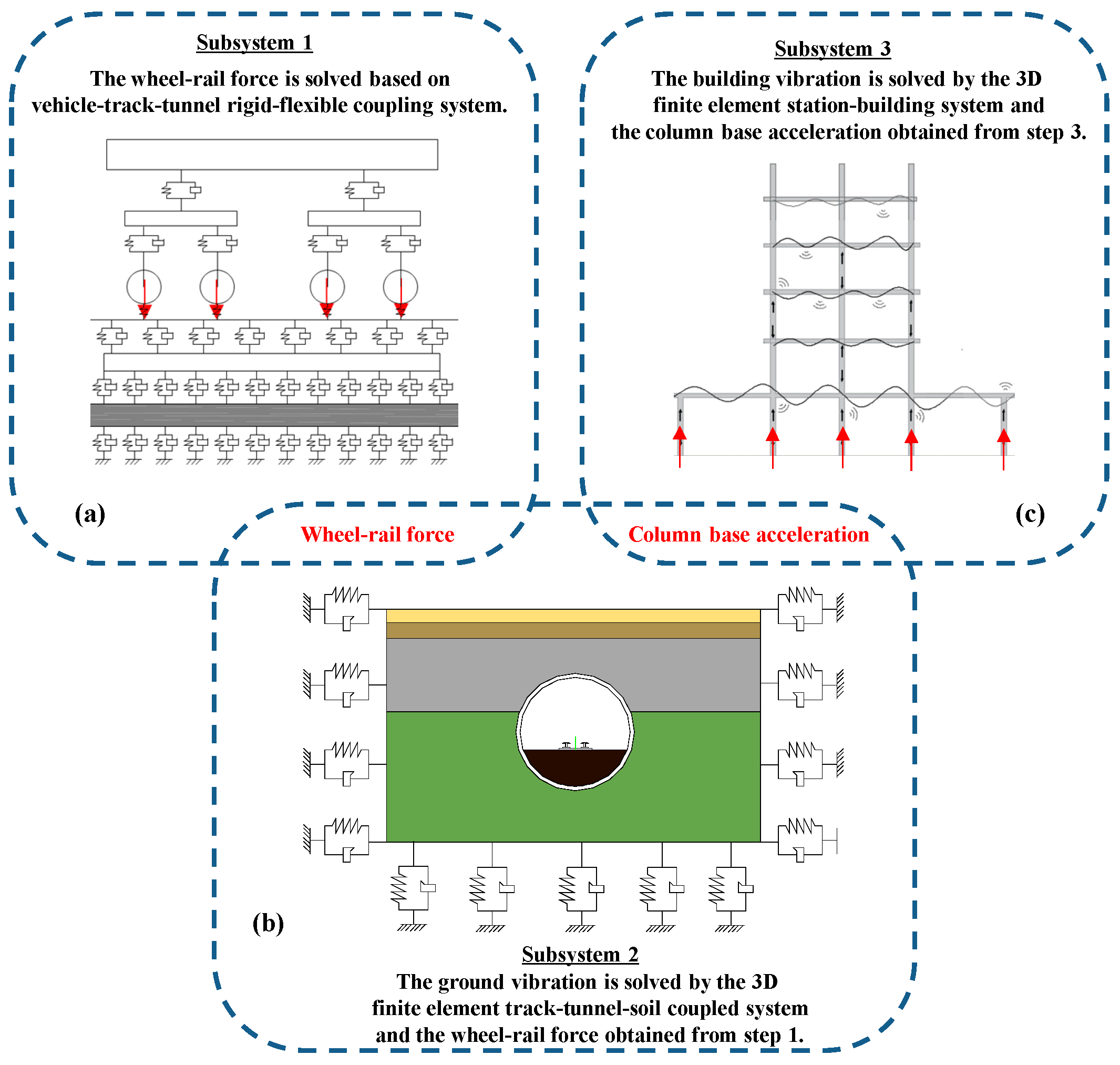
3.1. Simulation of Vibration Generation and Propagation

The numerical prediction model for train-induced ground vibrations was previously described by Xing et al. [22]. As such, only a brief description of the model is summarized here:
  • Utilizing the principles of the finite element analysis and dynamics of multi-body systems, a coupling model comprising the vehicle, track, and tunnel is developed. The vehicle model is represented as a rigid multi-body system consisting of 42 degrees of freedom, including a car body, two bogie frames, and four wheelsets, amounting to seven rigid body components in total. An analysis of the fixed track is conducted, resulting in the development of a flexible track–tunnel model that accounts for the elasticity of the rail, the resilience of fasteners, and the deformation of the track slab, along with the tunnel and its elastic supports. The Timoshenko beam model serves as the standard for the rail, maintaining an interval of 0.6 m. The slabs of the track and the tunnel structure are represented as solid components, the fasteners are depicted as linear spring–damper systems, and the elastic support provided by the soil is modeled as a uniformly distributed viscoelastic element with a stiffness of 60 MPa/m.
  • A 3D finite element subsystem is created for the track–tunnel–soil system; this model comprises the rail, fasteners, track slabs, tunnel, and soil. It stretches vertically for 80 m along the line, with a width of 100 m oriented perpendicular to the central line, and features a soil layer depth of 60 m. The mesh size for the rail beam elements is set at 0.1 m, while the grid for the solid elements of both the track slab and tunnel is configured at 0.5 m. The solid element mesh for the soil is categorized into three distinct regions; the central section features a grid size of 0.5 m, oriented perpendicular to both sides along the 0.8 m line, while the lower section has a grid size of 1.0 m. This finite element model is composed of 1260560 elements and has a total of 1341516 nodes.
  • The validation of the vehicle–track–tunnel–soil coupled numerical model is achieved through the analysis of ground vibration measurements. The simulation results align closely with the gathered experimental findings regarding both temporal and spectral characteristics.

3.2. Simulation of Vibration Reception

The station–building 3D FEM vibration reception model is established and illustrated in Figure 2. In the model, the geometrical dimensions of the beams, columns, doors, windows, and other components, as well as the spatial arrangement of the structures, are established depending on the existing conditions. The beam, structural column, and pile foundation of the structures, such as the metro stations and the over-track buildings, consist of three-dimensional elastic beams (unit beam 4), which can withstand tension, compression, bending, and torsion. The influence of shear deformation is not considered. It is assumed that the centerline is a straight normal line perpendicular to the mid-surface after deformation, thus facilitating stress hardening and a large deformation calculation. The walls, floors, and rafter foundation of the structure are a four-node elastic shell unit (shell63). Each node has 6 degrees of mobility in this unit. Due to stress stiffening and large deformability, each node can be analyzed for bending of the shell and the mechanical behavior of the thin film and is suitable for the analysis of shell structures of medium thickness.

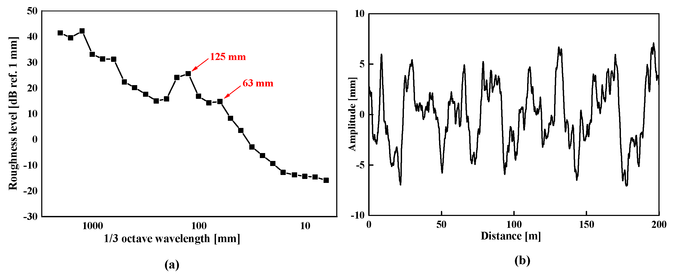
3.3. Track Irregularity

In this study, the irregularities of the track are viewed as a superimposition of typical rail corrugation alongside the initial track’s geometric imperfections, as shown in Figure 3. The irregularities in the track geometry are derived from the fifth-grade power spectral density formula proposed by U.S. railways; the range of wavelengths measures 0.5–200 m. For the rail corrugation, the wavelengths and the wave depths, respectively, measure 0.02–0.5 m and 0.05–0.10 mm. Among them, the significant wavelength and secondary significant wavelength are, respectively, 125 mm and 63 mm.

3.4. Column Base Dynamic Load

After the ground acceleration has been obtained by the numerical simulation as the input excitation, the uniform input method is adopted to calculate the dynamic response of the building structure under a train load; the interaction between the soil and structure is not considered. The motion of a structural system under uniform excitation is expressed as Equation (3).
m u ¨ + c u ˙ + k u = m u ¨ g t
where m, c, and k are the mass matrix, damping matrix, and stiffness matrix, respectively; u , u ˙ , and u ¨ are the displacement response, velocity response, and acceleration response, respectively; and u ¨ g t is the acceleration vector of the ground motion.

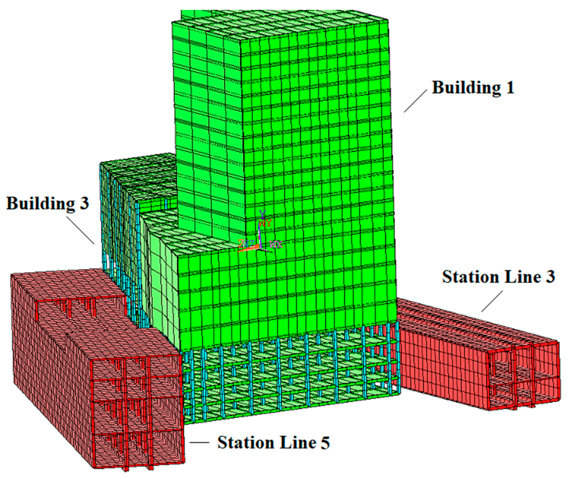
4. Case Study of Over-Track Buildings in a Subway Transfer Station

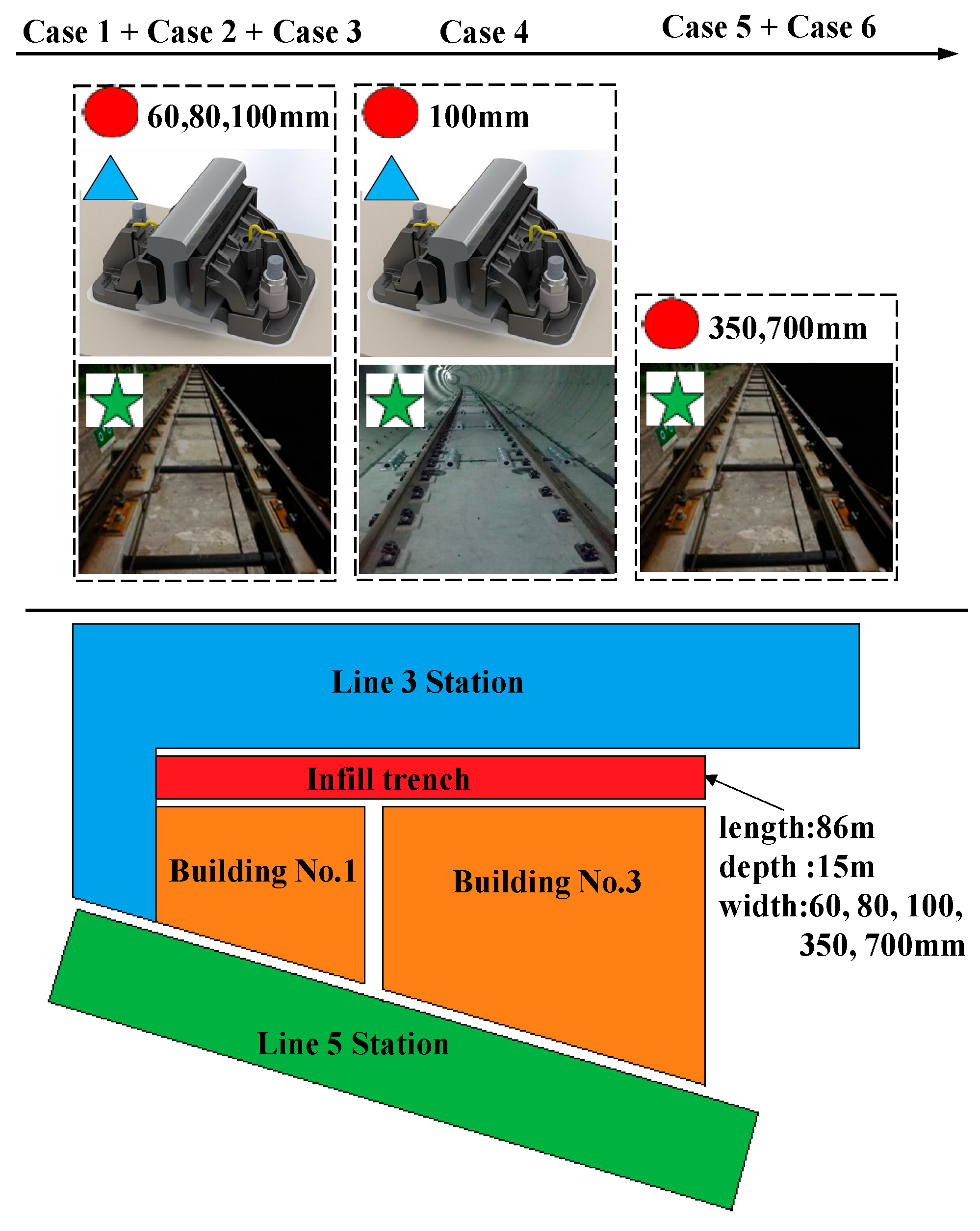
4.1. General Description

“Station” refers to the transfer station of Metro Line 3 and Line 5. The station of Line 3 is a 12 m island platform located on the second-floor basement; the station is roughly oriented in an east–west direction. Located in the block of over-track buildings, the station of Line 5 is a 13 m island platform located on the third-floor basement; this station is oriented in a southeast–northwest direction. The relative position of the station and the buildings is shown in Figure 4. The plan is to construct buildings above the transfer subway station. The over-track buildings include Building No. 1 (20th floor, 74.8 m high, frame structure), Building No. 2 (5th floor, 24.0 m high, frame–shear structure), and Building No. 3 (5th floor, 23.8 m high, frame–shear structure). Building No. 2 is more than 40 m from the station of Line 5 and Building No. 1 and Building No. 3 are surrounded by the stations of Line 3 and Line 5. Building No. 1 is considerably higher than the surrounding buildings and is considerably affected by train-induced ground vibrations. Building No. 3 is the closest to the two metro stations, and part of the building foundation is directly over the stations. Thus, we predicted the vibrations of Building No. 1 and Building No. 3 and constructed a 3D finite element model of the transfer station and over-track buildings to conduct a numerical analysis.

4.2. Dynamic Parameters

In Metro Line 3 and Line 5, the train consists of 6 “B-type” vehicles and operates at a speed of 60 km/h. The track structure consists of a 60 kg/m rail, a DZIII fastening system, and a fixed track slab. The station of Line 3 is 140 m long, and the station of Line 5 is 110 m long. For the convenience of the calculation, the length of the stations of both Line 3 and Line 5 is set at 250 m. Table 1 provides details of the model parameters.

4.3. Analysis of Numerical Results

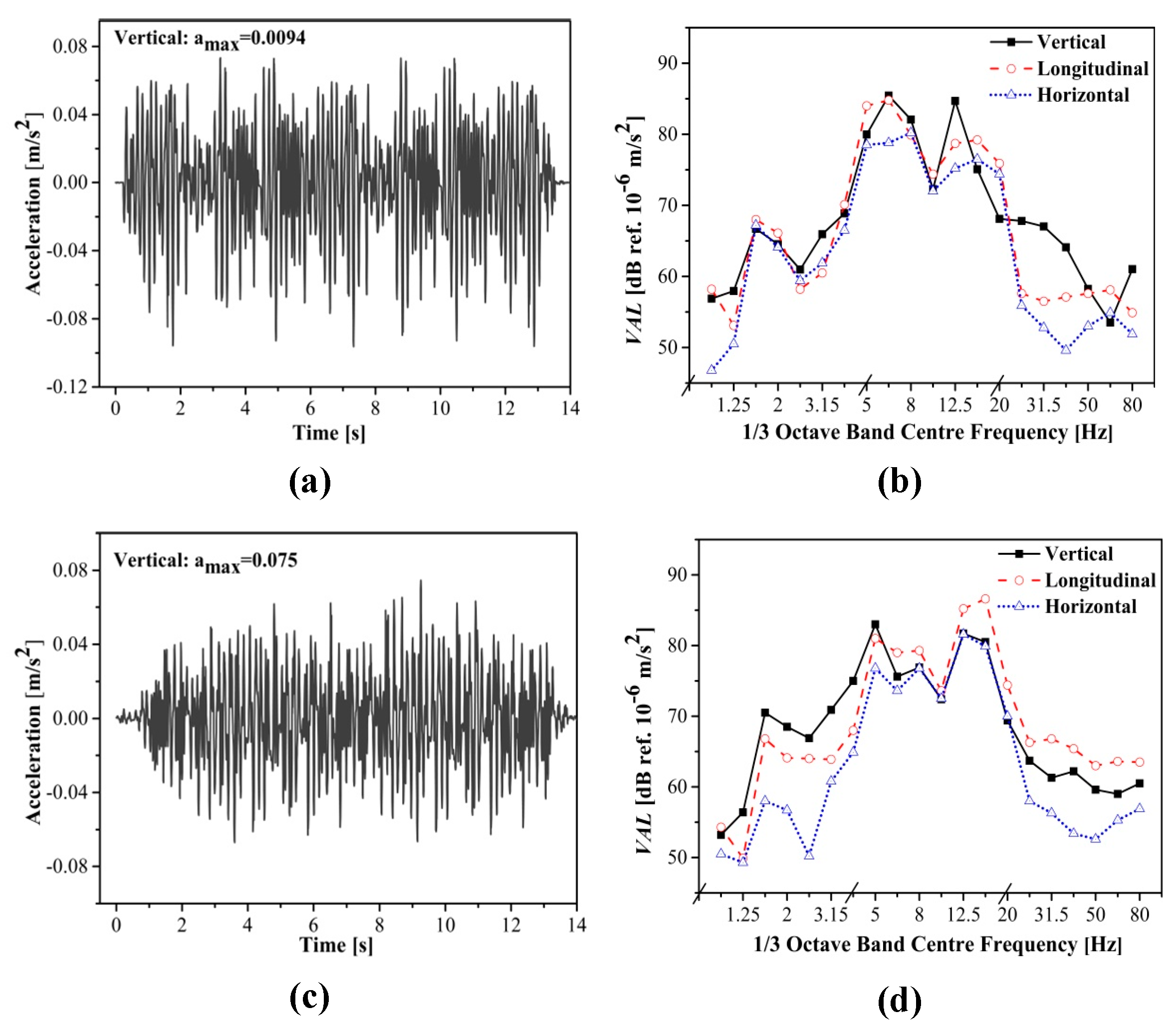
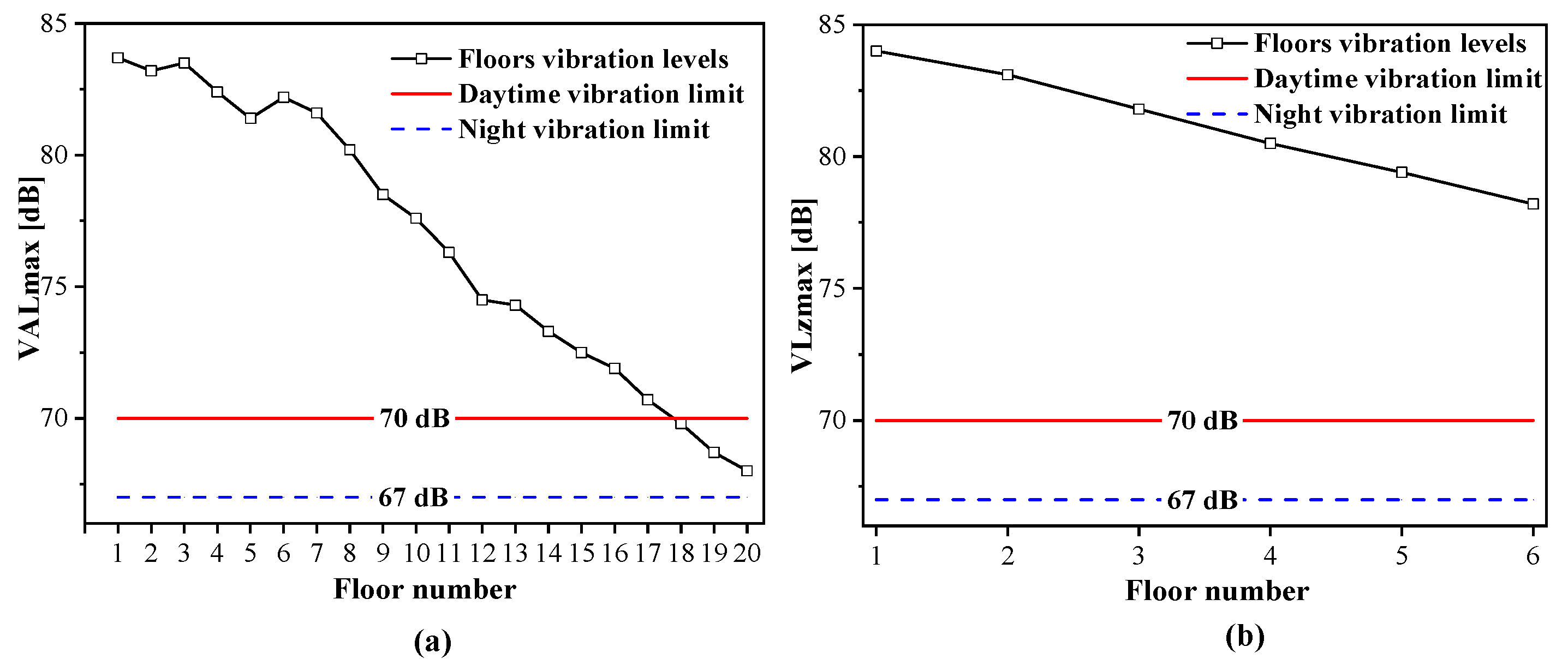
4.3.1. Building Foundation Response

Utilizing a model for predicting indoor secondary vibrations in over-track buildings situated above metro stations, the calculations are made regarding the building foundation’s vibration response in three different directions when metro trains enter the station at a constant speed (specifically, the vertical direction means perpendicular; the longitudinal direction is along the direction of the line; and the horizontal direction refers to the plane of the section of the track, i.e., perpendicular to the direction of the line). Because Building No. 3 is closest to the two metro stations and is located directly above the station, the column bases of the first row of columns adjacent to Building No. 3 are chosen to assess the vibration response of the building’s foundation.
Figure 5a,b show the vibration response of the building foundation when the train on Line 3 enters the station. The measured values of vibration acceleration in the vertical, longitudinal, and horizontal directions indicate peak levels of 0.0094 g, 0.0090 g, and 0.0057 g, respectively. The vibration level in the longitudinal direction is similar to that observed in the vertical direction. The lateral vibration observed is approximately 0.6 times that of the vertical direction, suggesting that the irregularities in the tracks produce a lateral force when the train enters the station. The vibration responses of the building foundation are low in the ranges of 1–5 Hz and 20–80 Hz and are relatively high and close in the frequency range of 5 Hz to 20 Hz. Specifically, the vibration has two peaks in the vertical direction near 6.3 Hz and 12.5 Hz, and the amplitudes are 85.4 dB and 84.7 dB, respectively. The vibration in the longitudinal direction peaks at 6.3 Hz, and the amplitude is 84.8 dB; the vibration in the horizontal direction peaks at 8 Hz, and the amplitude is 80.2 dB, indicating that the ground vibration has a low frequency.
Figure 5c,d show the induced vibration responses of the building foundation when the train on Line 5 enters the station. The measured values of vibration acceleration in the vertical, longitudinal, and horizontal directions indicate peak levels of 0.0075 g, 0.0081 g, and 0.0058 g, respectively. The main frequency of the vibration of the building foundation caused by Line 5 is between 4 Hz and 20 Hz, and most components have a low frequency. The maximum vibration acceleration level in the frequency ranges of 1–4 Hz and 20–80 Hz is 70.9 dB, and the peak appears at 3.15 Hz; the maximum vibration amplitude between 4 Hz and 20 Hz is 86.6 dB, and the peak is at 16 Hz.
As indicated by the comparison, when the trains on Line 3 and Line 5 enter the station, their effects on the building foundation’s vibration are comparably equivalent. The longitudinal and vertical vibration accelerations of Line 5 are marginally less than those of Line 3, yet the values for horizontal vibration acceleration appear to be similar.

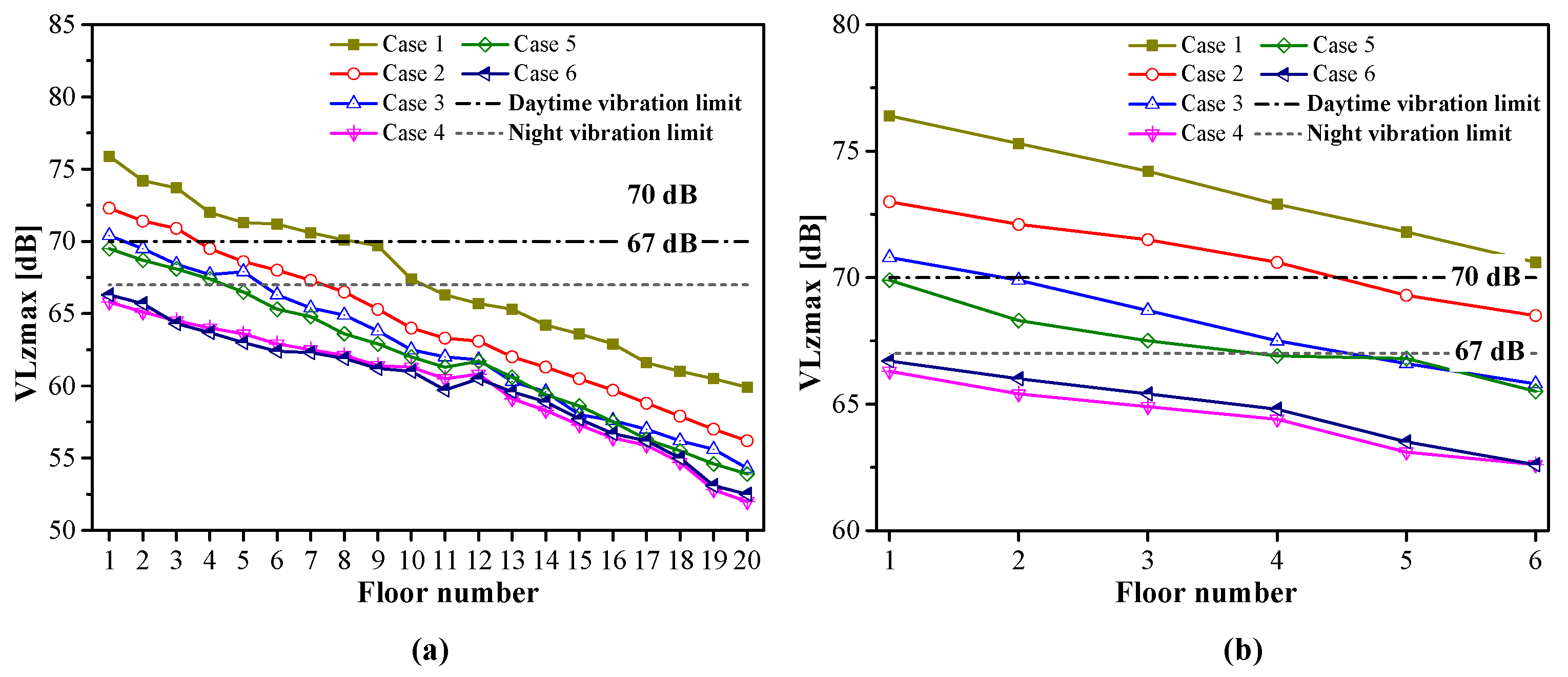
4.3.2. Indoor Vibration Assessment

Based on the response of the building foundation, this paper calculated the dynamic response of the over-track buildings under a train load. The vibration response of the floorboards was assessed by selecting the midpoint of the floorboards in the largest room located on each floor of Building No. 1 and Building No. 3. As the number of levels increases, the vibration levels in Building No. 1 diminish, while the peak vibrations are observed on floors 3, 6, and 7, as shown in Figure 6a.
The main reason is likely that the natural frequency of the main building structure approaches the dominant frequency of the vibration source. The VALmax of the first floor of Building No. 1 is 83.7 dB, exceeding the daytime standard by 13.7 dB and the nighttime standard by 16.7 dB. The VALmax on the 20th floor is 68.0 dB. Although the value does not exceed the daytime standard, the nighttime standard is exceeded by 1.0 dB. As seen in Figure 6b, the vibration intensity of Building No. 3 decreases with an increase in the number of floors. The VALmax of the first floor of Building No. 3 is 84.0 dB, exceeding the daytime standard by 14.0 dB and the nighttime standard by 17.0 dB. On the sixth floor, the VALmax is 78.2 dB, exceeding the daytime standard by 8.2 dB and the nighttime standard by 11.2 dB.
The results demonstrate that the indoor secondary vibrations in both buildings are considerably above the acceptable thresholds. The higher vibration levels are probably due to the inadequate energy dissipation capabilities of the top head platform. Effective control measures must be proposed for Line 3 and Line 5 to prevent adverse effects on the life and work of the building’s residents. In addition, the vibration attenuation differs for different floors due to the effects of the natural frequency. The natural frequency of the main structure should be different from the main frequency of the vibration source to prevent high vibration levels of the floors.

5. Vibration Mitigation by Comprehensive Control Strategies

If no vibration mitigation measures are implemented, the indoor vibration of Building No. 1 and Building No. 3 significantly exceeds the standard by up to 17.0 dB when the trains of Line 3 and Line 5 enter the station. The trains of Line 3 and Line 5 have a similar effect on the vibration of the building’s foundation. Therefore, vibration mitigation measures are implemented simultaneously for Line 3 and Line 5.
The secondary vibrations indoors caused by trains in buildings situated over tracks form a complex interrelated network that includes the vehicle, track, and foundation. Due to the conditions of the subway line, the damping fasteners could be replaced when the construction of Line 3 will be completed, and various vibration mitigation measures could be adopted for the track structure in Line 5. We focus on top-down comprehensive control strategies and combine the use of track damping structures and soil vibration isolation. Six types of vibration mitigation approaches (Case 1 to Case 6) are implemented (Table 2); the layout of the cases is shown in Figure 7. Specifically, the vertical stiffness of the Vanguard fastener is 30 kN/mm. Infill trenches with coarse sand of different widths are located around the cushion caps under the columns of the stations. The trenches have a density of 1979 kg/m3, an elastic modulus of 202.2 MPa, a Poisson’s ratio of 0.38, and a damping ratio of 0.034. The ladder-type track and the steel-spring floating slab track are two different vibration damping systems, which are typically used as vibration damping measures in certain areas. The details of the track structure components and calculation parameters are shown in Table 3.
Figure 8 illustrates the vibration response of each floor of the over-track buildings for the different cases of vibration mitigation. As shown in Figure 8a, the VALmax of Building No. 1 decreases after the six different vibration mitigation measures are implemented, but the effects are different for each case. Specifically, the vibration response is the highest for Case 1 on each floor and the lowest for Case 4 or Case 6. After control measures are taken in Case 4, the VALmax of the first floor of Building No. 1 is 65.8 dB. The values decrease with an increase in the floor number until reaching 52.0 dB (20th floor), indicating that Case 4 provides the best results for vibration mitigation in Building No. 1. After control measures are taken in Case 6, the response peak of Building No. 1 does not exceed 66.3dB, which also meets the requirements.
As shown in Figure 8b, the six different vibration mitigation measures have a certain control effect on the indoor secondary vibration of Building No. 3, but the effects are different, among which Case 4 and Case 6 are the best. For Case 4, the VALmax of the first floor of Building No. 3 is 66.3 dB and that of the sixth floor is 62.6 dB. For Case 6, the VALmax of the first floor of Building No. 3 is 66.7 dB and that of the 6th floor is 62.6 dB, both of which meet the requirements of Building No. 3 for vibration mitigation.
Therefore, the conditions of Case 4 and Case 6 are applied to Line 3 and Line 5 to mitigate the vibration. In other words, the vibration-damping fasteners of Line 3 are replaced with the less rigid Vanguard fasteners. A 100 mm wide isolation trench is installed between Line 3 and the over-track buildings, and steel-spring floating slabs are adopted for Metro Line 5. Alternatively, a 700 mm wide isolation trench is installed between Line 3 and the over-track buildings, and steel-spring floating slabs are used for Line 5. This approach significantly reduces the indoor secondary vibration of the buildings.

6. In-Site Test Measurement
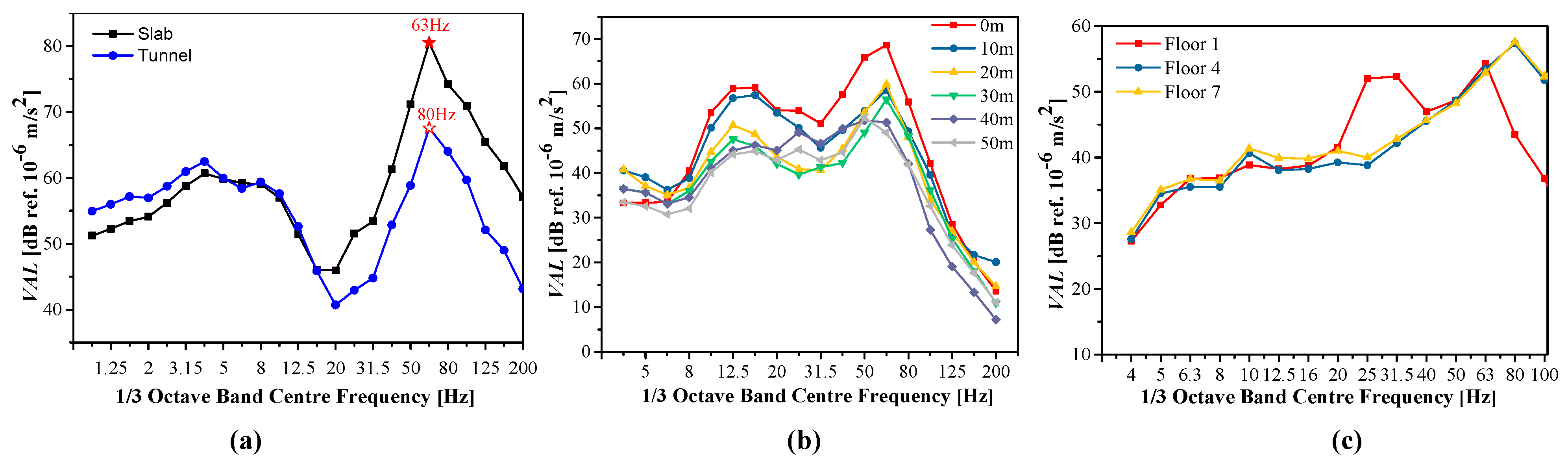
6.1. Test Scheme

These measurements were implemented in the subway transfer station of Chengdu Metro Line 3. The control measures outlined in Case 6 were used. A 700 mm wide isolation trench was installed near Line 3, along with fixed track sections and DZIII fasteners. The purpose of the testing setup was to analyze vibration source, ground vibration, and building indoor vibration of Line 3. The results provide a reference for train-induced indoor secondary vibrations of over-track buildings after Line 5 will be opened.
The measurement locations included (1) setup A for the vibration source, (2) setup B for the ground vibration, and (3) setup C for the building indoor secondary vibration. The measurement location for setup A was located in the middle of the track slab. Two sensors for measuring vertical acceleration were positioned on the track slab and the tunnel wall 1.25 m from the rail surface, illustrated in Figure 9a. At setup B, a series of ground observation points were established, consisting of six locations for measuring ground vibrations, positioned at 0 m, 10 m, 20 m, 30 m, 40 m, and 50 m from the central line along a trajectory that was perpendicular to the train’s running direction. At setup C, a residential building with a masonry structure near the station and 21.6 m from the center of the track was selected. Measurements were obtained on the 12th floor of the building, and no measures were taken to reduce vibrations. The acceleration sensors were located on the first, fourth, and seventh floors, as shown in Figure 9c.

6.2. Analysis of Test Results

The vibration responses of setup A, setup B, and setup C are shown in Table 4. The PPA at setup A is 1.29 m/s2 for the slab and 0.106 m/s2 for the tunnel. The VLzmax of the slab is 98.4 dB and that of the tunnel is 79.5 dB. At setup B, the ground vibration attenuates with the distance; the maximum value of PPA is 0.081 m/s2 and the VLzmax at 0 m is 71.64 dB. At setup C, the VALmax values on floor 1, floor 4, and floor 7 are 58.2 dB, 55.0 dB, and 54.6 dB, respectively. The measurements were conducted in the morning; thus, the daytime vibration limit of 70 dB applies. The building vibration was below the limit. The wheels and rail were in good condition when Line 3 was running. The top-down integrated vibration reduction design for the transmission path proves to be an effective control method.
Figure 10a illustrates the response characteristics related to the vibration source in the slab and the tunnel. It has been noted that the dominant frequency of vibration for the slab is approximately 63 Hz at its peak of 80.5 dB; in the tunnel, it is around 80 Hz with 64.0 dB. The vibration attenuates vertically along the track.
Figure 10b illustrates the changes in the 1/3 octave spectra of vertical vibrations with increasing the distance from the center of the track. It has been noted that the ground vibration at 0 m is approximately 14.8 dB, greater than that at 50 m. The ground vibration in the far-field is significantly lower. The dominant frequency of the ground vibration is in the range of 50–80 Hz. Figure 10c shows the building vibration on different floors. It is observed that the dominant frequency of the indoor secondary vibration in the building is 12.5–80 Hz, and the amplitude of the indoor vibration gradually decreases as the floor number increases. The lower floors of the buildings were significantly affected by the train-induced vibration. The main vibration frequency was slightly different for the different floors due to the test conditions and the building structure.

7. Conclusions and Discussion

A numerical model based on a three-step approach, consisting of rigid–flexible coupling dynamics models to simulate vibration generation and propagation, and a finite element model to simulate vibration reception, was created to study the train-induced building vibrations in a subway transfer station. Different vibration mitigation measures derived from comprehensive control strategies were assessed. An in-site test as an important part of prediction and evaluation was conducted in the full propagation path of metro vibrations. The following conclusions are drawn:
(1) Track irregularity and roughness on the wheel/rail surfaces, such as corrugation, can increase railway environmental vibration impacts. Therefore, a flexible method based on the rigid–flexible coupled dynamic of a vehicle–track system is proposed under a more complicated external excitation. Combined with a three-step approach, the details of the train-induced vibration and numerical analysis method in this paper can be adopted for estimating over-track building vibration responses before and during construction.
(2) Over-track buildings on a subway transfer station have relatively high indoor vibration levels due to the low damping energy dissipation of the top platform; there are mainly low frequencies between 4 Hz and 20 Hz. The vibration attenuation was different on different floors of the building, which was attributed to the natural frequency of the building. The natural frequency of the main structure should be different from the main frequency of the vibration source to prevent high vibration levels of the floors.
(3) A top-down comprehensive design of vibration mitigation based on the transmission path is efficient to propose a practical control method since the goal is engineering application. the Vanguard fasteners or an isolation trench in Metro Line 3 and a steel-spring floating slab track in Metro Line 5 significantly reduce train-induced indoor secondary vibrations. Through field testing along the full propagation path, the metro vibration effects on nearby station buildings meet the standard criteria. A wider infill trench can effectively block the transmission of vibrations from the ground into the building.
In summary, the proposed numerical model accurately predicted train-induced building indoor vibrations, and the top-down vibration reduction design based on the transmission path provided a practical control method. The findings from this research could serve as valuable references and guidance for engineering applications. Future research will involve comprehensive examinations of the vibrations and noise resulting from trains, and the validation of the numerical method will be accomplished using more field-measured data. This study did not consider the building vibration response under more complex excitation situations, such as when trains on both routes entered the respective stations nearly simultaneously. Therefore, future studies should consider trains operating under more complex conditions and braking at different speeds near over-track buildings for prediction vibrations. In addition, new control measures should be investigated to eliminate low-frequency vibrations in over-track buildings to promote TOD.

Author Contributions

Conceptualization, M.X. and J.Z.; methodology, M.X.; software, M.X.; validation, M.X., J.Z. and D.C.; formal analysis, J.Z.; investigation, M.X.; resources, D.C.; data curation, D.C.; writing—original draft preparation, M.X.; writing—review and editing, D.C.; visualization, J.Z.; supervision, J.Z.; funding acquisition, M.X. All authors have read and agreed to the published version of the manuscript.

Funding

This research was funded by [Basic Research Foundation of TaihuLight of China; Natural Science Foundation of the Higher Education Institutions of Jiangsu Province; Wuxi University Research Start-up Fund for Introduced Talents] grant number [No. K20221050; No. 24KJB580015; No. 2022r026]; And the APC was funded by [No. K20221050].

Data Availability Statement

The data presented in this study are available on request from the corresponding author due to privacy.

Conflicts of Interest

Author Dingqing Chen was employed by the company Wuxi Metro Operation Co., Ltd. The remaining authors declare that the research was conducted in the absence of any commercial or financial relationships that could be construed as a potential conflict of interest.

References

  1. Takemiya, H.; Goda, K. Prediction of ground vibration induced by high-speed train operation. In Proceedings of the 5th International Conference on Sound and Vibration, University of Adelaide South Australia, Adelaide, Australia, 15–18 December 1997; Volume 5, pp. 2681–2688. [Google Scholar]
  2. François, S.; Schevenels, M.; Galvín, P.; Lombaert, G.; Degrande, G. A 2.5D coupled FE-BE methodology for the dynamic interaction between longitudinally invariant structures and a layered halfspace. Comput. Methods Appl. Mech. Eng. 2010, 199, 1536–1548. [Google Scholar]
  3. Cao, Y.; Xia, H.; Lombaert, G. Solution of moving-load-induced soil vibrations based on the Betti–Rayleigh Dynamic Reciprocal Theorem. Soil Dyn. Earthq. Eng. 2010, 30, 470–480. [Google Scholar] [CrossRef]
  4. Gupta, S.; Liu, W.; Degrande, G.; Lombaer, G.; Liu, W. Prediction of vibrations induced by underground railway traffic in Beijing. J. Sound Vib. 2006, 310, 608–630. [Google Scholar]
  5. Fiala, P.; Degrande, G.; Augusztinovicz, F. Numerical modelling of ground-borne noise and vibration in buildings due to surface rail traffic. J. Sound Vib. 2007, 301, 718–738. [Google Scholar] [CrossRef]
  6. Thompson, D.; Kouroussis, G.; Ntotsios, E. Modelling, simulation and evaluation of ground vibration caused by rail vehicles. Veh. Syst. Dyn. 2019, 57, 936–983. [Google Scholar] [CrossRef]
  7. Celebi, E. Three-dimensional modelling of train-track and sub-soil analysis for surface vibrations due to moving loads. Appl. Math. Comput. 2006, 179, 209–230. [Google Scholar] [CrossRef]
  8. Wang, L.; Wang, P.; Wei, K.; Dollevoet, R.; Li, Z. Ground vibration induced by high speed trains on an embankment with pile-board foundation: Modelling and validation with in situ tests. Transp. Geotech. 2022, 34, 100734. [Google Scholar] [CrossRef]
  9. Yang, Y.B.; Liang, X.; Hung, H.H.; Wu, Y.l. Comparative study of 2D and 2.5D responses of long underground tunnels to moving train loads. Soil Dyn. Earthq. Eng. 2017, 97, 86–100. [Google Scholar]
  10. Yang, Y.B.; Liu, S.J.; Chen, W.; Tan, Q.; Wu, Y.T. Half-space response to trains moving along curved paths by 2.5D finite/infinite element approach. Soil Dyn. Earthq. Eng. 2021, 145, 106740. [Google Scholar]
  11. Yang, Y.; Hung, H.; Chang, D. Train-induced wave propagation in layered soils using finite/infinite element simulation. Dyn. Earthq. Eng. 2003, 23, 263–278. [Google Scholar] [CrossRef]
  12. Jones, S.; Hunt, H. Predicting surface vibration from underground railways through inhomogeneous soil. J. Sound Vib. 2012, 331, 2055–2069. [Google Scholar] [CrossRef]
  13. Xia, H.; Chen, J.; Wei, P.; Xia, C.; De Roeck, G.; Degrande, G. Experimental investigation of railway train-induced vibrations of surrounding ground and a nearby multi-story building. Earthq. Eng. Eng. Vib. 2009, 8, 137–148. [Google Scholar] [CrossRef]
  14. Kouroussis, G.; Conti, C.; Verlinden, O. Experimental study of ground vibrations induced by Brussels IC/IR trains in their neighbourhood. Mech. Ind. 2013, 14, 99–105. [Google Scholar]
  15. Zou, C.; Wang, Y.; Wang, P.; Guo, J. Measurement of ground and nearby building vibration and noise induced by trains in a metro depot. Sci. Total Environ. 2015, 536, 761–773. [Google Scholar] [CrossRef] [PubMed]
  16. Zou, C.; Wang, Y.; Moore, J.; Sanayei, M. Train-induced field vibration measurements of ground and over-track buildings. Sci. Total Environ. 2017, 575, 1339–1351. [Google Scholar] [CrossRef] [PubMed]
  17. GB10071; Measurement Method of Environmental Vibration of Urban Area. Ministry of Ecology and Environment: Beijing, China, 1988.
  18. GB/T 50355; Standard of Limit and Measurement Method of Vibration in the Room of Residential Buildings. Ministry of construction: Beijing, China, 2018.
  19. TB/T 3152; Measurement of Railway Environmental Vibration. China Academy of Railway Sciences Corporation Limited: Beijing, China, 2007.
  20. JGJ/T 170; Standard for Limit and Measuring Method of Building Vibration and Secondary Noise Caused by Urban Rail Transit. Ministry of Housing and Urban-Rural Development: Beijing, China, 2009.
  21. ISO2631/1; Mechanical vibration and shock: Evaluation of human exposure to whole-body vibration—Part 1: General requirements. International Organization for Standardization: Geneva, Switzerland, 1997.
  22. Xing, M.; Zhao, C.; Wang, P.; Lu, J.; Yi, Q. A Numerical Analysis of Ground Vibration Induced by Typical Rail Corrugation of Underground Subway. Shock. Vib. 2019, 2019, 8406813. [Google Scholar]
Figure 1. Schematic representation of the numerical simulation procedure: (a) subsystem 1 represents “vibration generation”; (b) subsystem 2 represents “vibration propagation”; and (c) subsystem 3 represents “vibration reception”.
Buildings 15 01024 g001
Figure 2. Subway transfer station–building 3D FEM subsystem model.
Buildings 15 01024 g002
Figure 3. Track irregularity in simulation: (a) roughness level spectra based on the measurement in a typical underground subway and (b) superimposed wheel–rail excitation.
Buildings 15 01024 g003
Figure 4. Schematic representation of the over-track buildings and transfer station.
Buildings 15 01024 g004
Figure 5. Building No. 3’s response when the Line 3 train enters the station in the (a) time domain and (b) frequency domain; Building No. 3’s response when the Line 5 train enters the station in the (c) time domain and (d) frequency domain.
Buildings 15 01024 g005
Figure 6. Maximum Z-weighted vibration level of each floor of (a) Building No. 1 and (b) Building No. 3.
Buildings 15 01024 g006
Figure 7. Layout of the vibration mitigations.
Buildings 15 01024 g007
Figure 8. Vibration response of each floor for the different cases of vibration mitigation: (a) Building No. 1 and (b) Building No. 3.
Buildings 15 01024 g008
Figure 9. Measurement setup at the Line 3 transfer station: (a) vibration source, (b) ground vibration and (c) building indoor secondary vibration.
Buildings 15 01024 g009
Figure 10. The 1/3 octave spectra of vibration acceleration at different setups: (a) vibration source at setup A; (b) ground vibration at setup B; and (c) building vibration at setup C.
Buildings 15 01024 g010
Table 1. Main calculation parameters.
ElementParameterUnitValue
VehicleMass of car bodykg39,000
Mass of bogiekg3600
Mass of wheel setkg1600
Mass moment of inertia of car bodykg·m21,400,000
Mass moment of inertia of car bogiekg·m21760
Vertical stiffness of primary suspensionkN/mm1.7
Vertical damping of primary suspensionkN·s/m60
Vertical stiffness of primary suspensionkN/mm0.45
Vertical damping of primary suspensionkN·s/m60
TrackFastener support spacingm0.625
Fastener stiffnesskN/mm35
Fastener dampingkN·s/m20
Slab length × width × thicknessM × m × m5.6 × 2.5 × 0.4
Slab densitykg/m32500
Slab Young’s modulusGPa35
BuildingDensitykg/m32500
Young’s modulusGPa32.5
Poisson’s ratio-0.4
Damping ratio-0.05
Table 2. Design of vibration mitigation approaches.
MetroCase 1Case 2Case 3Case 4Case 5Case 6
Line 3Vanguard fasteners
+
Isolation trench
60mm wide
Vanguard fasteners
+
Isolation trench 80mm wide
Vanguard fasteners
+
Isolation trench 100mm wide
Vanguard
fasteners
+
Isolation trench 100mm wide
Infill trench 350 mm wideInfill trench 700 mm wide
Line 5Ladder trackLadder trackLadder trackSteel springLadder trackLadder track
Table 3. Main parameters of the track.
Steel-Spring Floating Slab Track Ladder-Type Track
Structure PartsParametersValueStructure Parts ParametersValue
Floating slabYoung’s modulus (GPa)3.50 Ladder sleeperYoung’s modulus (GPa)3.50
Length (m)0.25 Length (m)6.15
Width (m)3.0 Width (m)0.46
Height (m) 0.35 Height (m) 0.175
Density (kg/m)2500 Density (kg/m)2500
Steel spring Vertical stiffness (N/m)6 × 106Filled steel stubPoisson’s ratio0.3
Vertical damping (N·s/m)17,000 Young’s modulus (GPa)21
Shear hingeShear stiffness (N/m)5 × 109 Density (kg/m)2808
Fastener Vertical stiffness (N/m)4 × 107Damping material under sleeper Vertical stiffness (N/m)1.5 × 107
Vertical damping (N·s/m)9.8 × 104 Vertical damping (N·s/m)10,000
Table 4. Vibration levels at setup A, setup B, and setup C (“—” in the table indicates missing data).
SetupSitePointPPA (m/s2)VLzmax (dB)VALmax (dB)
Setup ASlabO11.2998.4
TunnelO20.10679.5
Setup B0 mP10.08171.64
10 mP20.05064.27
20 mP30.03761.98
30 mP40.02458.91
40 mP50.01958.19
50 mP60.01656.80
Setup AFloor 1Q10.01256.0
Floor 4Q20.00653.9
Floor 7Q30.00253.6
Disclaimer/Publisher’s Note: The statements, opinions and data contained in all publications are solely those of the individual author(s) and contributor(s) and not of MDPI and/or the editor(s). MDPI and/or the editor(s) disclaim responsibility for any injury to people or property resulting from any ideas, methods, instructions or products referred to in the content.

