Abstract
To investigate the mechanical behavior of precast columns with openings in the beam–column joint core area under axial loads, a systematic study was conducted to examine the effects of the opening parameters on the axial mechanical performance of precast columns. Two sets of six precast concrete column specimens, with opening ratios of 14% and 22%, respectively, were designed and subjected to axial compression tests. The failure patterns, opening ratios in the core area, and other relevant parameters of the specimens were thoroughly analyzed. Additionally, a finite element model incorporating material non-linearities was developed using ABAQUS (2022) software, and parametric numerical simulations were conducted to further explore the structural response. The results indicated that the variations in the opening ratio had no significant effect on the cracking load of the specimens. However, as the opening ratio increased, the peak load of the compressed columns increased by 8.6%, and the ductility factor increased by 12.9%. The study also reveals that opening ratios below 30%, the casing thickness, and the bolt preload have minimal impact on the bearing capacity of precast columns. These findings provide theoretical support for optimizing hole sizes in dry bolted connections for precast concrete structures.
1. Introduction
Prefabricated buildings offer numerous advantages, including reduced construction durations, superior project quality, and lower labor costs, thereby streamlining construction and management processes [1,2,3,4,5,6,7,8]. A critical aspect of prefabricated buildings is the beam–column connection method, which significantly influences the structural performance [9,10,11]. The joints are often considered as the weakest component and are frequently the primary cause of severe structural damage. In extreme cases, such weaknesses may lead to progressive collapse [12,13,14,15,16,17,18,19,20].
Connection techniques for prefabricated buildings can be broadly categorized into wet connections and dry connections. Wet connections involve the on-site assembly of precast components using cast-in-place methods or grouting [21,22,23,24,25], which fail to fully leverage the advantages of precast concrete structures. In contrast, dry connections are typically achieved through bolting or welding, with bolted connections demonstrating significant potential and playing a pivotal role in advancing dry connection technologies [26].
Aninthaneni et al. [27] developed angle steel connections for dry-connected prefabricated frame structures. Gardner et al. [28] designed five sets of prefabricated beams with T-shaped cross-sections and conducted quasi-static experiments and finite element analyses to investigate the bolt energy dissipation, ductility, and bending capacity at the joints. The new joints exhibited superior mechanical properties, including enhanced bending resistance, energy dissipation capacity, deformation ability, and ductility, compared to joints without bolted connections. Ertas et al. [29] designed four types of joints, i.e., bolted connection joints, corbel welded joints, post-poured concrete connection joints, and cast-in-place concrete joints, and conducted quasi-static experiments on all four joints. Except for the corbel welded joint, all other joints exhibited sound seismic performance. Notably, the bolted connection joint demonstrated exceptional ductility, load-bearing capacity, and construction advantages. Ma et al. [30] investigated the mechanical properties of a new dry-type high-strength bolted connection joint for prefabricated buildings. The failure mode of the new dry-type beam–column connection joint was plastic failure, characterized by a full hysteretic curve and excellent energy dissipation performance. Liu et al. [31] proposed an insert-type beam–column joint with a steel–concrete composite system, connecting prefabricated beams and columns using bolts and embedded steel components. Static tests were conducted on seven insert-type composite joints and one cast-in-place joint. The new joint had lower initial stiffness and energy dissipation capacity but higher ultimate load-bearing capacity, which was significantly influenced by the beam cross-section. Ding et al. [32] proposed a new semi-dry composite beam–column joint and studied its mechanical performance under cyclic loading. Finite element simulations and seismic performance tests revealed that the joint exhibited good plastic deformation ability and energy dissipation capacity. Zhang et al. [33] tested prefabricated beam–column joints connected with ordinary long bolts. The specimens exhibited excellent overall load-bearing performance, significant joint deformation, and good ductility. Additionally, a stiffness calculation formula for semi-rigid joints was also proposed.
Furthermore, as a critical load-bearing component, precast columns require detailed force analyses. Liu et al. [34] conducted tests on seven prefabricated cruciform section thin-concrete-encased steel (PCS-TCES) short columns. The PCS-TCES short columns exhibited excellent axial compressive strength and crack resistance. Tao et al. [35] investigated a new type of cruciform steel–concrete column. Its axial compressive capacity was higher than that of conventional steel–concrete columns, with effective collaborative working performance observed among the steel pipes. Han et al. [36] studied the seismic performance of nine L-shaped steel–concrete columns, exhibiting good seismic performance. An increase in seismic performance was observed when the cross-sectional dimensions of the columns and the length of the column legs were increased. Despite significant progress in optimizing connection joints and composite column systems, the critical relationship between the design of openings in the core area of precast columns and axial force transmission mechanisms has not yet been fully revealed, in particular the weakening effects on the concrete cross-section induced by bolted connection joints.
Based on the experimental research of Ma et al. [30] on a novel concrete beam–column bolted connection joint, this study addressed the need for openings in the core area of precast columns to facilitate bolted connections between beams and columns. These openings lead to a reduction in the concrete cross-section of the column core. Since columns primarily bear vertical loads in the building, column failure can cause significant structural damage, potentially leading to the collapse of the entire building [37]. Therefore, the current work analyzed, through experiments, theoretical approaches, and finite element simulations, the impact of the opening ratio in the joint core area on the mechanical properties of precast columns. This study aimed to refine the research content and provide theoretical support for the in-depth investigation of dry bolted connection joints.
2. Experimental Program
2.1. Experimental Specimen
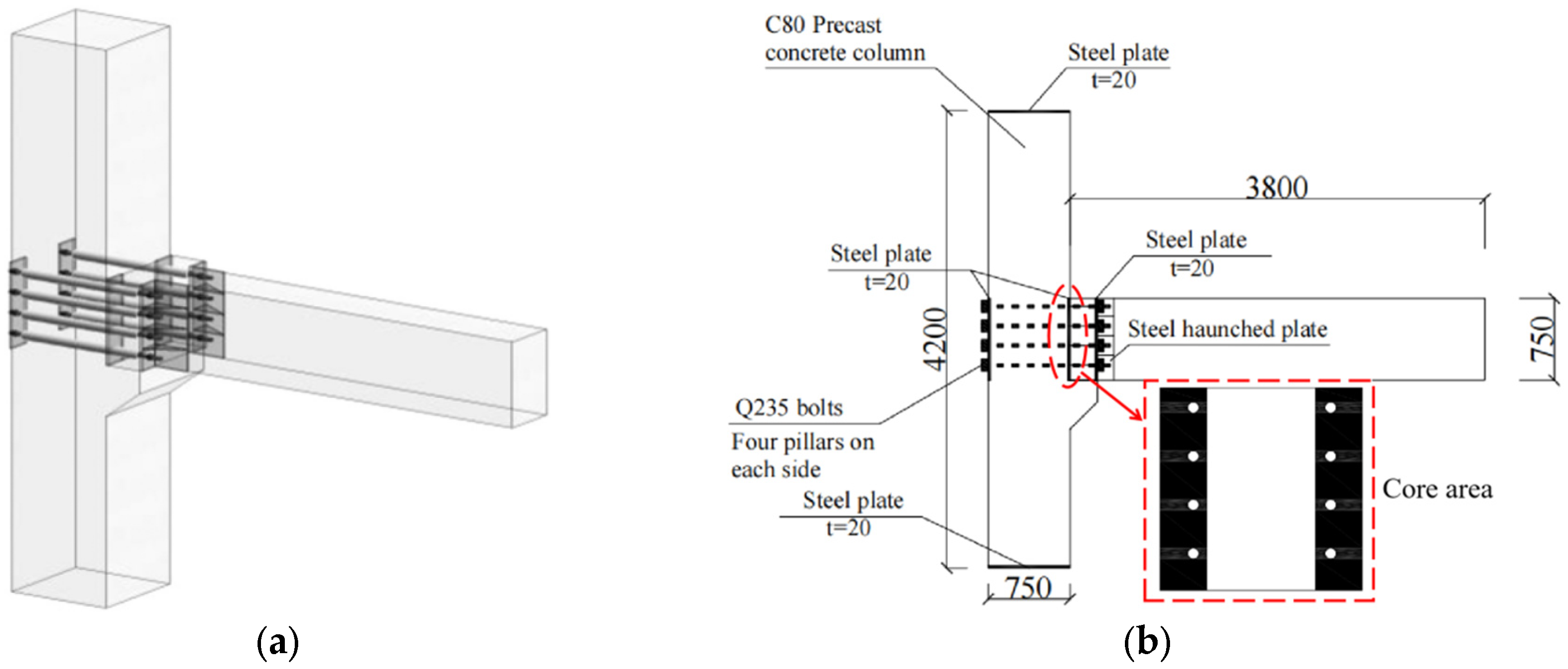
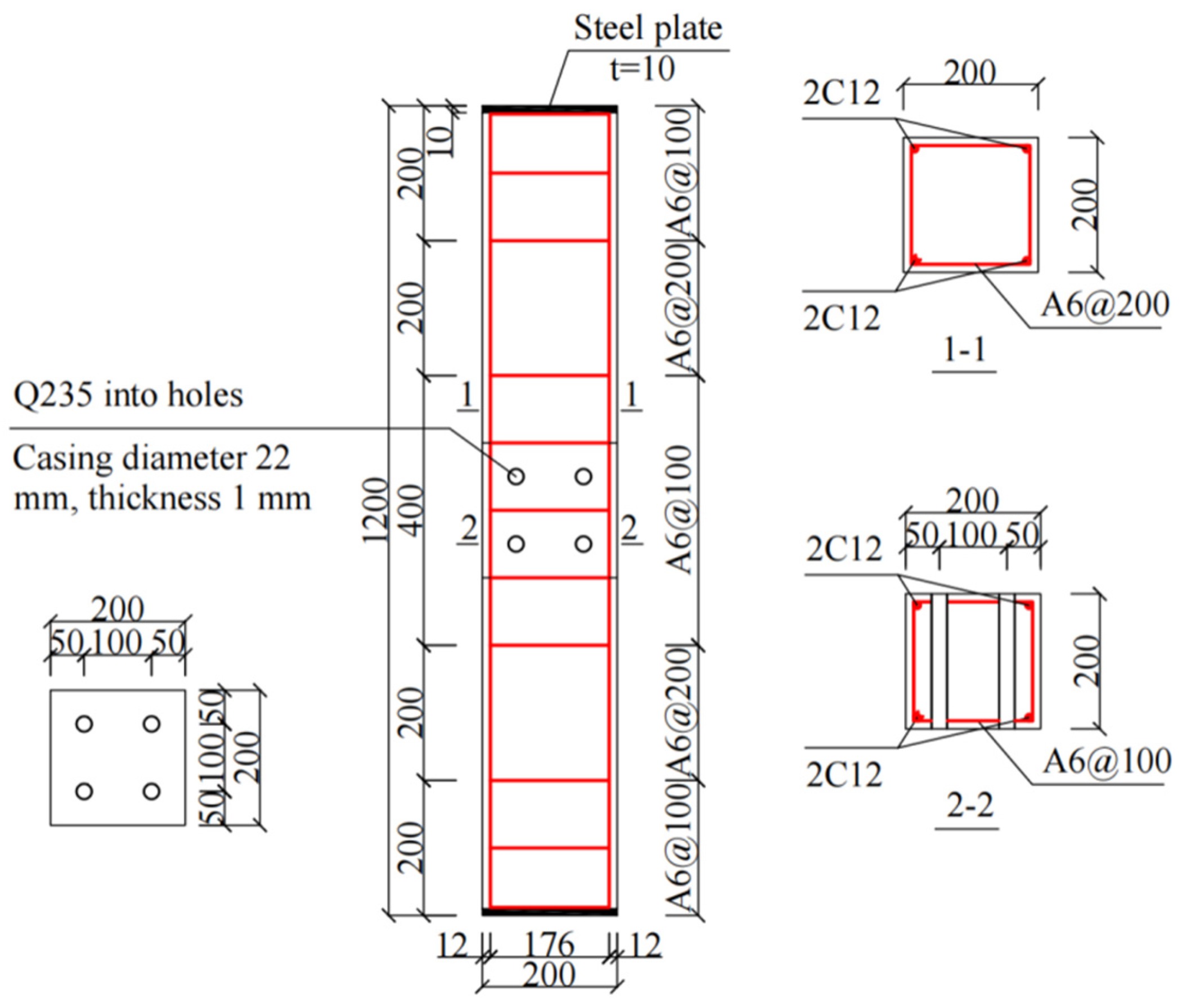
An experimental investigation of bolted beam–column joints (specimens depicted in Figure 1) was conducted in the study by Ma et al. [30], wherein the cross-sectional dimensions of the precast columns were 750 mm × 750 mm. The existing literature suggests that the scaling of specimens does not significantly influence the accuracy of the outcomes [38]. Therefore, two groups of six scaled precast concrete column specimens with varying opening ratios were utilized for experimental investigations, as detailed in Table 1. The cross-sectional dimensions of the specimen columns were 200 mm × 200 mm, with a height of 1200 mm. The design parameters and reinforcement specifications are presented in Table 2 and Figure 2.

Figure 1.
Test joint in the literature [30]: (a) perspective view; (b) specimen diagram.

Table 1.
Specimen parameters and main reinforcement.
Table 2.
Design parameters of precast columns.
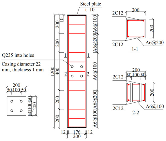
Figure 2.
Dimensions and cross-sectional details of test specimens.
Considering the impact of cross-section weakening on the mechanical performance of columns, this study focused on investigating the mechanical behavior of concrete columns with an opening ratio below 25%. Consequently, the experimental plan included a comparative analysis of concrete columns with opening ratios of 15% and 25%. Due to size limitations of the holes in the casings, holes were created using steel pipes with diameters of 14 mm and 22 mm. The corresponding cross-sectional opening ratios of the specimens were measured as 14% and 22%, approaching 15% and 25%, respectively.
2.2. Material Properties
Table 3 presents the material properties utilized in the study. The precast columns were reinforced with HRB400 for longitudinal reinforcement, demonstrating a yield strength of 416.7 MPa and a tensile strength of 619.2 MPa. For transverse reinforcement, HPB300 was employed, exhibiting a yield strength of 335 MPa and a tensile strength of 488.3 MPa. The casing was fabricated from Q235 steel with a yield strength of 238.6 MPa and a tensile strength of 411.2 MPa. The grade of concrete was C20, with the test cubes achieving a compressive strength of 23.10 MPa.
Table 3.
Material properties.
2.3. Test Setup and Instruments
The on-site test setup and its schematic diagram are presented in Figure 3. To accurately simulate the real-world structural conditions, a hinged support system was implemented at the base of the concrete column. This support system, measuring 250 mm × 250 mm in cross-section, was engineered with a substantial load-bearing capacity of 1200 kN to accommodate the anticipated structural loads. The support was specifically designed to allow the rebound point to occur at the mid-height of the concrete column during the testing procedure. To ensure the experimental precision and specimen’s stability, the hinged support was securely anchored to the testing apparatus by four high-strength bolts, guaranteeing the exact positioning and alignment of the test specimen. To prevent the sudden collapse of the precast column at the end of the test, safety measures, including protective barriers, were implemented around the specimen.
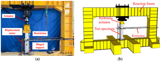
Figure 3.
Test setup: (a) on-site test setup; (b) schematic diagram.
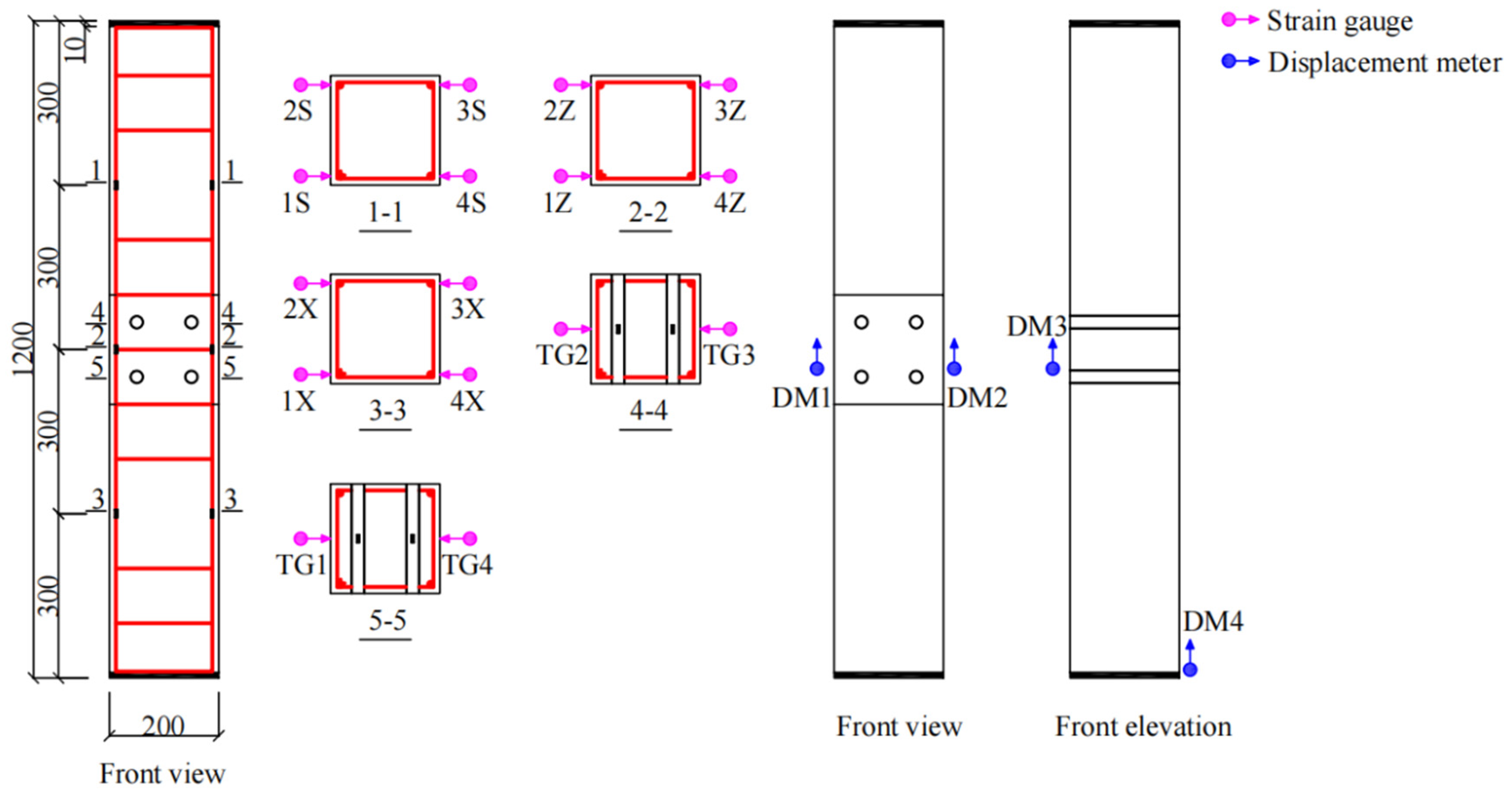
To accurately measure the internal forces and deformations of the structure during the loading process, appropriate measuring instruments were installed prior to the test. Figure 4 illustrates the configuration of displacement meters and strain gauges. The strain gauges for reinforcements were positioned along the longitudinal axis of the column reinforcements, while the strain gauges for casings (TG1–TG4) were arranged at the mid-height of the column. Displacement meters (DM1–DM3) were placed in the core area of the precast column. In addition, a displacement meter DM4 was installed at the base of the column on its front side to calibrate the displacement data.
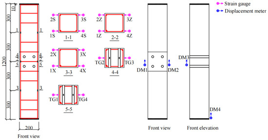
Figure 4.
Layout of measurement points. Note: 1S–4S, 1Z–4Z, and 1X–4X represent strain gauges positioned on various column reinforcements; TG1–TG4 signify strain gauges located on distinct casings; DM1–DM3 indicate displacement meters for diverse locations.
2.4. Loading Scheme
The specimen was subjected to a vertical static load using a force–displacement controlled loading method. Before the formal loading process, the loading apparatus was calibrated. The initial load capacity was set to 10% of the anticipated maximum load, and both the loading device and the compressed specimen were inspected and unloaded to ensure proper alignment and functionality. The first stage of loading was set to 150 kN, with subsequent load increments of 50 kN until cracks began to appear. After cracks appeared, displacement-controlled loading was applied at a rate of 0.5 mm/min, with each loading increment set to 1 mm, until the specimen was damaged.
3. Analysis of Experimental Results
3.1. Failure Mode
- ZY14 Series (Opening Ratios of 14%)
- (1)
- ZY14-1
When the displacement at the top of the column reached 0.58 mm under a load of 300 kN, fine cracks appeared in the upper one-third of the column. With a displacement of 0.86 mm at the top of the column and a load of 350 kN, a new crack formed at the front of the column, while the crack on the left side extended toward the edge. As the load increased, the crack propagation intensified. At a load of 600 kN and a top displacement of 1.27 mm, the upper concrete exhibited a fish scale pattern, and fine cracks occurred in the lower concrete, with the crack width on the left side reaching 1.25 mm. When the load reached 675 kN and the top displacement was 2.12 mm, numerous cracks emerged in the non-encrypted concrete area at the top of the column, accompanied by concrete failure, as depicted in Figure 5a.

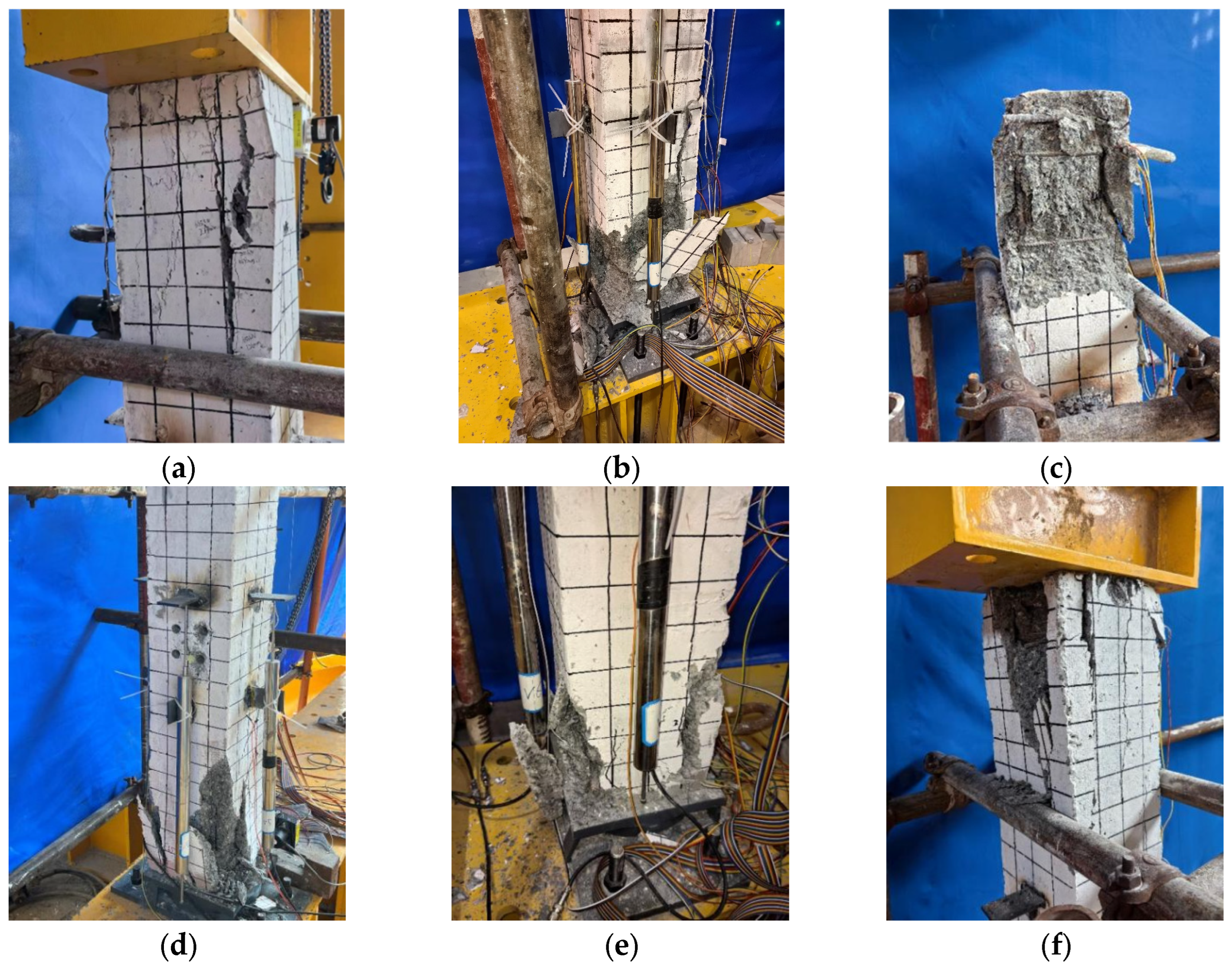
Figure 5.
Damage patterns of specimens: (a) ZY14-1; (b) ZY14-2; (c) ZY14-3; (d) ZY22-1; (e) ZY22-2; (f) ZY22-3.
- (2)
- ZY14-2
With a displacement of 0.66 mm at the top of the column and a load of 300 kN, a fine crack appeared at the front bottom of the column. Under a load of 342 kN, vertical cracks developed downward and the crack widths expanded. At a load of 400 kN and a top displacement of 1.04 mm, the crack width at the bottom left side increased to 0.49 mm. When the top displacement reached 1.65 mm under a load of 655 kN, the first crack at the bottom widened to 1.25 mm, and concrete spalling occurred at the bottom edges. At a load of 677 kN and a top displacement of 2.01 mm, extensive cracks appeared in the non-encrypted concrete area at the top, accompanied by slight bulging cracks and large-scale concrete spalling, as illustrated in Figure 5b.
- (3)
- ZY14-3
When the displacement at the top of the column reached 0.65 mm under a load of 300 kN, fine cracks appeared at the bottom of the column. At a load of 450 kN and a top displacement of 1.32 mm, cracks formed at the top, and a transverse through-crack appeared, leading to concrete spalling. With a load of 627 kN and a top displacement of 2.18 mm, multiple fine cracks developed near the main crack in the non-encrypted concrete area at the top, resulting in concrete spalling, as described in Figure 5c.
- ZY22 Series (Opening Ratios of 22%)
- (1)
- ZY22-1
At a displacement of 0.66 mm and a load of 300 kN, cracks appeared at both the top and bottom of the column. Under a load of 396 kN and a top displacement of 0.87 mm, new cracks with a width of 0.31 mm formed at the bottom. As the load increased, the cracks expanded toward the center. At a load of 629 kN and a top displacement of 1.53 mm, slight concrete spalling emerged in the lower part. At a load of 708 kN and a top displacement of 1.81 mm, slight bulging and concrete spalling occurred at the bottom, as shown in Figure 5d.
- (2)
- ZY22-2
At a displacement of 0.65 mm and a load of 300 kN, cracks appeared at the bottom left and right sides, with widths of 0.15 mm and 0.12 mm, respectively. Under a load of 450 kN and a top displacement of 1.55 mm, a crack with a width of 0.11 mm formed at the front, and the crack on the right side expanded to 0.38 mm. At a load of 712 kN and a top displacement of 2.08 mm, the cracks near the main crack in the non-encrypted concrete area at the bottom extended toward the edge, leading to concrete spalling, as illustrated in Figure 5e.
- (3)
- ZY22-3
At a displacement of 0.62 mm and a load of 300 kN, a crack with a width of 0.11 mm appeared at the front and top of the column. Under a load of 450 kN and a top displacement of 1.2 mm, the crack extended toward the center, widening to 0.43 mm, and a new crack formed at the top left. At a load of 500 kN and a top displacement of 1.35 mm, the crack at the front and top of the column expanded to 0.5 mm, and slight concrete spalling occurred. At a load of 730 kN and a top displacement of 2.12 mm, multiple fine cracks appeared in the non-densified concrete at the top, leading to concrete collapse, as described in Figure 5f.
In summary, the failure of the concrete columns was primarily due to the cracking and crack development on the concrete in the non-encrypted area, ultimately leading to the collapse of the entire column, The main experimental phenomena are shown in Table 4. Notably, the core area of the joint with openings showed no signs of failure.
Table 4.
Main test phenomena of specimens.
3.2. Load Displacement Curve
Figure 6 illustrates the load–displacement curves derived from the average of two sets of test data. The curves for both sets of axially compressed specimens can be divided into elastic and elastoplastic phases. During the elastic phase, the curve behavior is primarily influenced by the elastic modulus of the material. Both the ZY14 and ZY22 specimens exhibited a cracking load of 300 kN. At this load, the ZY14 specimen experienced a displacement of 0.63 mm, while the ZY22 specimen was displaced by 0.61 mm, representing a 3.2% reduction in displacement compared to the ZY14 specimen. As the displacement increased, the bearing capacity of the ZY22 specimen rose slightly faster than that of the ZY14 specimen.
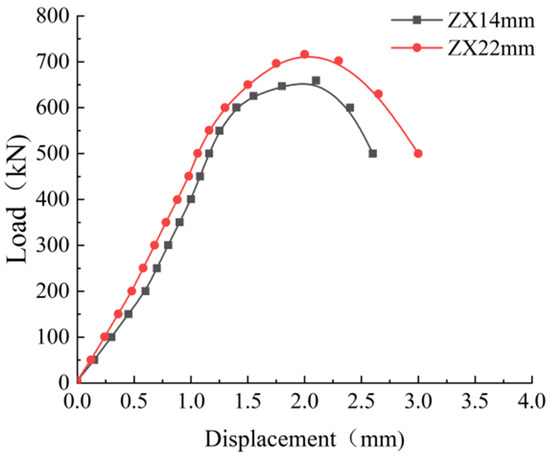
Figure 6.
Load–displacement relationship.
The maximum loading capacities for the ZY14 and ZY22 specimens were 659.66 kN and 716.66 kN, with corresponding axial displacements of 2.1 mm and 2.0 mm, respectively. The ZY22 specimen demonstrated an 8.6% increase in peak loading capacity compared to the ZY14 specimen, while its axial displacement was 4.8% lower. The absence of damage in the core area of the joint with openings in both specimen groups indicates that the failure in the non-encrypted concrete area of the column significantly influenced the load-bearing capacity of the specimen.
3.3. Strain of Reinforcement
Figure 7 presents the load–strain curves at position 1Z for both the ZY14 and ZY22 specimens, highlighting distinct mechanical behaviors between the two groups. At the cracking point, the ZY14 specimen exhibited a strain of −250.6 με, while the ZY22 specimen showed a significantly higher strain of −445.8 με, representing a 78% increase in reinforcement strain for the latter. A similar trend is reflected in the maximum load, where the reinforcement strains reached −1269.5 με for ZY14 and −1428.4 με for ZY22, indicating a 12.5% higher strain in the ZY22 specimen. The observed differences in strain behavior can be attributed to the greater cross-sectional weakening in the core area of the ZY22 specimen, which results in elevated cross-sectional stress concentrations and consequently leads to increased reinforcement strain development throughout the loading process.
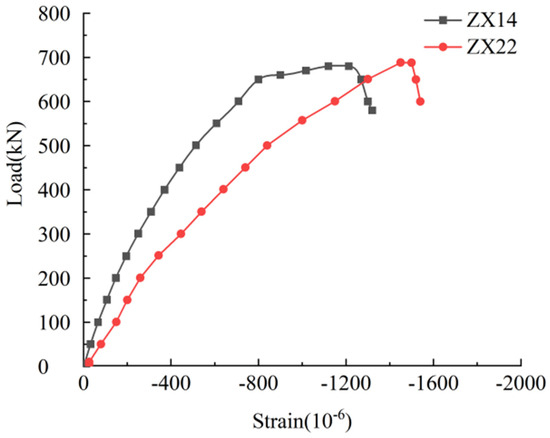
Figure 7.
Load–reinforcement strain relationship.
3.4. Ductility Coefficient
The displacement ductility (μ) of reinforced concrete columns is a critical parameter for evaluating their seismic performance. It represents the specimen’s ability to undergo plastic deformation and can be calculated using Equation (1).
where represents the displacement when the vertical load is reduced to 80% of its maximum value and is the yield displacement determined using the method proposed by Park [39].
The ductility coefficients obtained from the two sets of test specimens are summarized in Table 5. The ductility coefficient (μ) of the compression specimen is directly proportional to the opening ratio in the core area. For the specimen with an opening ratio of 14%, the ductility coefficient was 1.25, while for the specimen with an opening ratio of 22%, it increased to approximately 1.4. The ductility coefficient of the ZY22 specimen was 12.9% higher than that of the ZY14 specimen. This indicates that the ductility coefficient increases with the opening ratio in the core area. The creation of openings in the core area reduces the cross-sectional area of the concrete, leading to higher strain in the core area and consequently an increase in the ductility coefficient. However, the difference in ductility coefficients between the specimens is not significant.
Table 5.
Ductility coefficients of test specimens.
4. Finite Element Analysis
4.1. Material Models
The uniaxial stress–strain relationship of concrete specified in the Code for the Design of Concrete Structures [40] was used to simulate the constitutive relationship of the concrete components, with the compressive strength of concrete taken according to the compressive performance test, and an elastic modulus of 3 × 10⁴ N/mm2, Poisson’s ratio of 0.2, and density of 2.4 × 10³ kg/m3 were adopted. The CDP (concrete damaged plasticity) was selected, which utilizes the orthotropic elastic damage theory with the tensile and compressive plasticity theory to characterize the non-linear behavior of concrete, accounting for non-linearity, stiffness degradation, and strain rate effects on the material’s properties [35,41]. The primary parameters considered in our analysis, including the dilation angle, eccentricity, compressive strength ratio (), biaxial ultimate compressive strength-to-uniaxial ultimate compressive strength ratio (), and viscosity coefficient, along with their respective values, are listed in Table 6. The reinforcements were described by the bilinear isotropic hardening model [42]. The reinforcements would break during the test; therefore, the ductile damage model available in ABAQUS was used, necessitating the definition of a cumulative damage model to simulate the fracture of the metal. The tensile strength of the reinforcements was determined based on empirical testing. Poisson’s ratio was taken as 0.3.
Table 6.
Concrete plasticity parameters.
4.2. Element Types
The load transfer mechanism was analyzed using an ABAQUS finite element analysis (FEA). Figure 8 illustrates the FEA model of the precast column. An eight-node solid element with reduced integration (C3D8R) was employed to simulate the non-linear behavior of the concrete column, while a two-node truss element (T3D2) was used to model the reinforcement. The casing was affixed to the concrete surface using a tie-binding connection, which established the interaction relationship through the ‘surface-to-surface’ contact method. Considering the stress distribution of the specimen, the mesh was coarsely subdivided. The mesh sizes were set to 20 mm for the precast column, 25 mm for the reinforcement, and 5 mm for the casing.
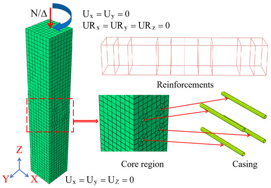
Figure 8.
Grid division of model specimens.
4.3. Boundary Conditions
To accurately replicate the internal force distribution observed in the actual structure, a reference point was established at the top of the column and rigidly coupled to its top surface. The column’s base was modeled as a hinged support, allowing rotational freedom while restricting translational displacement. For precise numerical simulations, the loading protocol was defined using the Smooth Amplitude function in ABAQUS, which generates a continuous and stable amplitude curve to ensure controlled load application. This approach, combined with displacement-based loading, enabled accurate simulations of the experimental loading process. A vertical load was subsequently applied to the reference point at the top of the column, effectively representing the loading conditions of the physical test while maintaining computational efficiency and numerical stability.
4.4. Finite Element Analysis Results
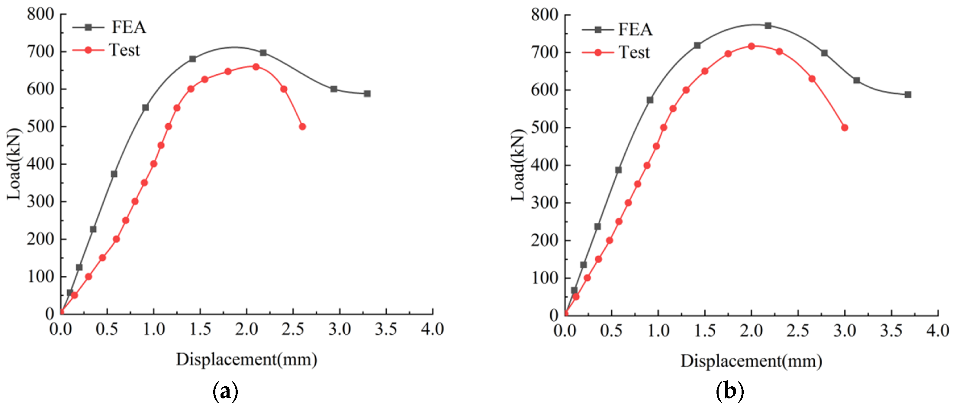
Figure 9 compares the load–displacement curves obtained from the experimental results and finite element predictions. For specimen ZY14, the peak load from the experimental results is 8% lower than that of the analytical model, with a 5% difference in the corresponding axial displacement at peak load, as plotted in Figure 9a. Similarly, for specimen ZY22, the experimental peak load is 7% lower than the analytical model, with a 10% difference in the corresponding axial displacement, as depicted in Figure 9b. Discrepancies between the experimental and simulation results may arise from variations in the uniformity of the concrete distribution among specimens or differences in reinforcement positioning during construction. Additionally, the curve from finite element analysis exhibits a relatively flat descending segment, while the experimental curves show a steeper load drop during this phase. This difference is likely due to stress concentration during testing, leading to localized damage. The simulated specimens assume idealized boundary conditions, load application, and material distribution, which are difficult to replicate in actual construction. As a result, the overall performance of the experimental specimens was slightly lower than the simulation results but remained consistent with real-world conditions.

Figure 9.
Load–displacement curves comparison between experimental and simulation results: (a) ZY14; (b) ZY22.
4.5. Finite Element Specimen Damage Morphology Analysis
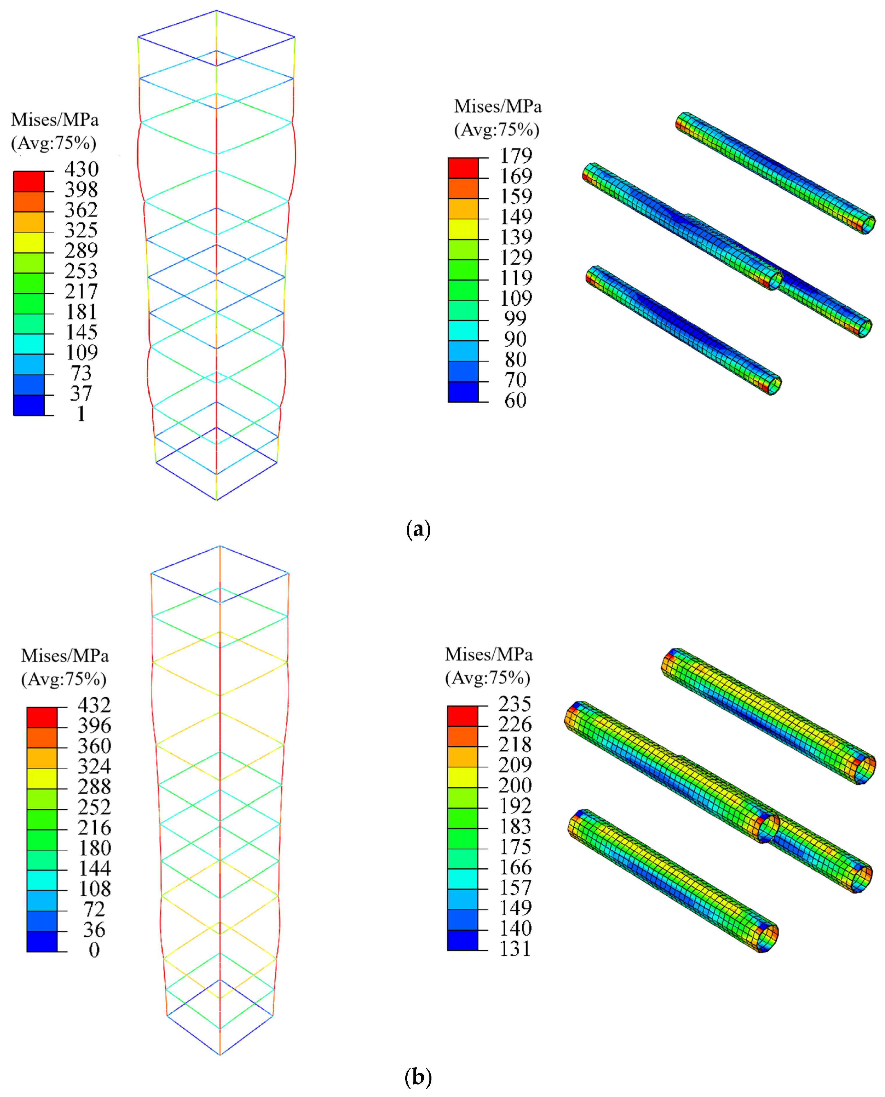
Figure 10 illustrates the strain distribution of the specimens during the failure phase. At failure, the non-encrypted concrete area exhibits more significant deformation. Additionally, the strain values in the core area of the opening increase with the size of the opening. Figure 11 depicts the stress distribution in the reinforcement and casing during specimen failure. At failure, the casing in the core area of specimen ZY22 experienced higher stress levels due to the smaller concrete cross-section. Consequently, both the reinforcement and casing in specimen ZY22 were subjected to greater stress compared to specimen ZY14.
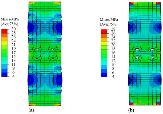
Figure 10.
Simulation of destructive strain in specimen: (a) ZY14; (b) ZY22.
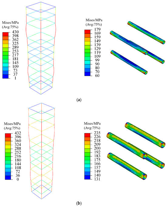
Figure 11.
Simulation of specimen reinforcements and casing stresses: (a) ZY14; (b) ZY22.
5. Parametric Study
The influence of the opening ratio in the core area on the strength of the concrete columns was comprehensively investigated using ABAQUS simulation software. Seven types of specimens, labeled PO-0 to PO-6, were modeled with varying opening ratios. These specimens were designed based on the parameters outlined in Section 4 and shared the same cross-sectional dimensions as the ZY14 specimens. The design parameters are summarized in Table 7.
Table 7.
Design parameters of specimens with different opening ratios.
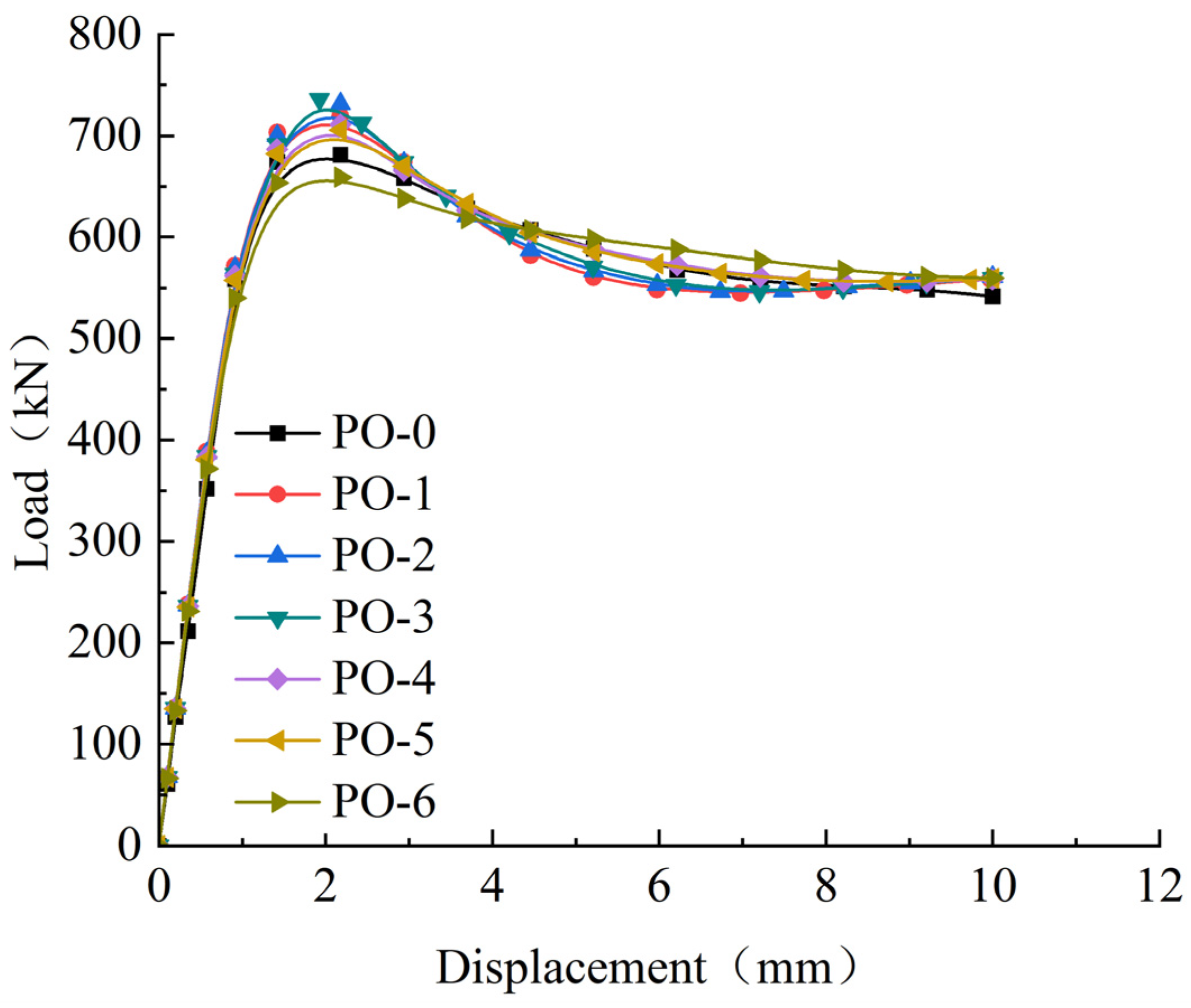
Figure 12 illustrates the load–displacement curves of specimens with different opening ratios. Within the elastic stage (0–1 mm displacement), the growth trends of the curves are nearly identical. Upon entering the elastoplastic stage, the load–displacement curves of the six specimen groups exhibit varying degrees of change. The peak load of the specimens varies with the opening ratio. The PO-3 specimen achieves a load capacity of 739 kN, while the load capacities of the other specimens (PO-0 to PO-2 and PO-4 to PO-6) decrease by 9.3%, 3.7%, 0.6%, 3.1%, 5.1%, and 10.8%, respectively, compared to PO-3. The data indicate that when the opening ratio is between 14% and 30%, the overall compressive load capacity of the specimens remains relatively stable. However, when the opening ratio reaches 34%, a significant reduction in load capacity can be observed. At an opening ratio of 22%, the strengthening effect of the casing in the core area is offset by the weakening effect of the opening ratio. Beyond this point, the strengthening effect of the casing diminishes, the weakening effect of the opening ratio becomes more pronounced, and the axial compressive load capacity decreases significantly at an opening ratio of 30%.
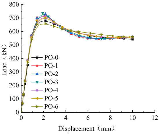
Figure 12.
Load−displacement curves corresponding to different opening ratios.
The ductility coefficients (μ) of specimens PO-0 to PO-6 are summarized in Table 8. The opening ratio in the core area of the compression specimens is positively correlated with the ductility coefficient. For instance, the PO-1 specimen, with an opening ratio of 14%, has a ductility coefficient of 2.35, while the PO-6 specimen, with an opening ratio of 38%, exhibits a ductility coefficient of 3.3. The ductility coefficient of the PO-6 specimen is 38% higher than that of the PO-1 specimen, further confirming the positive correlation between the ductility coefficient and the opening ratio.
Table 8.
Ductility coefficients of specimens with different opening ratios.
5.1. Casing Thickness
The influence of the casing thickness in the core area on the compressive behavior of the concrete columns was investigated through finite element modeling using ABAQUS software. Based on the validated modeling parameters from Section 4, five specimen groups (CT-1 to CT-5) with varying casing thicknesses were designed, maintaining the same cross-sectional dimensions as the ZY14 and ZY22 prototype columns. The key design parameters are summarized in Table 9.
Table 9.
Design parameters of specimens with different casing thicknesses.
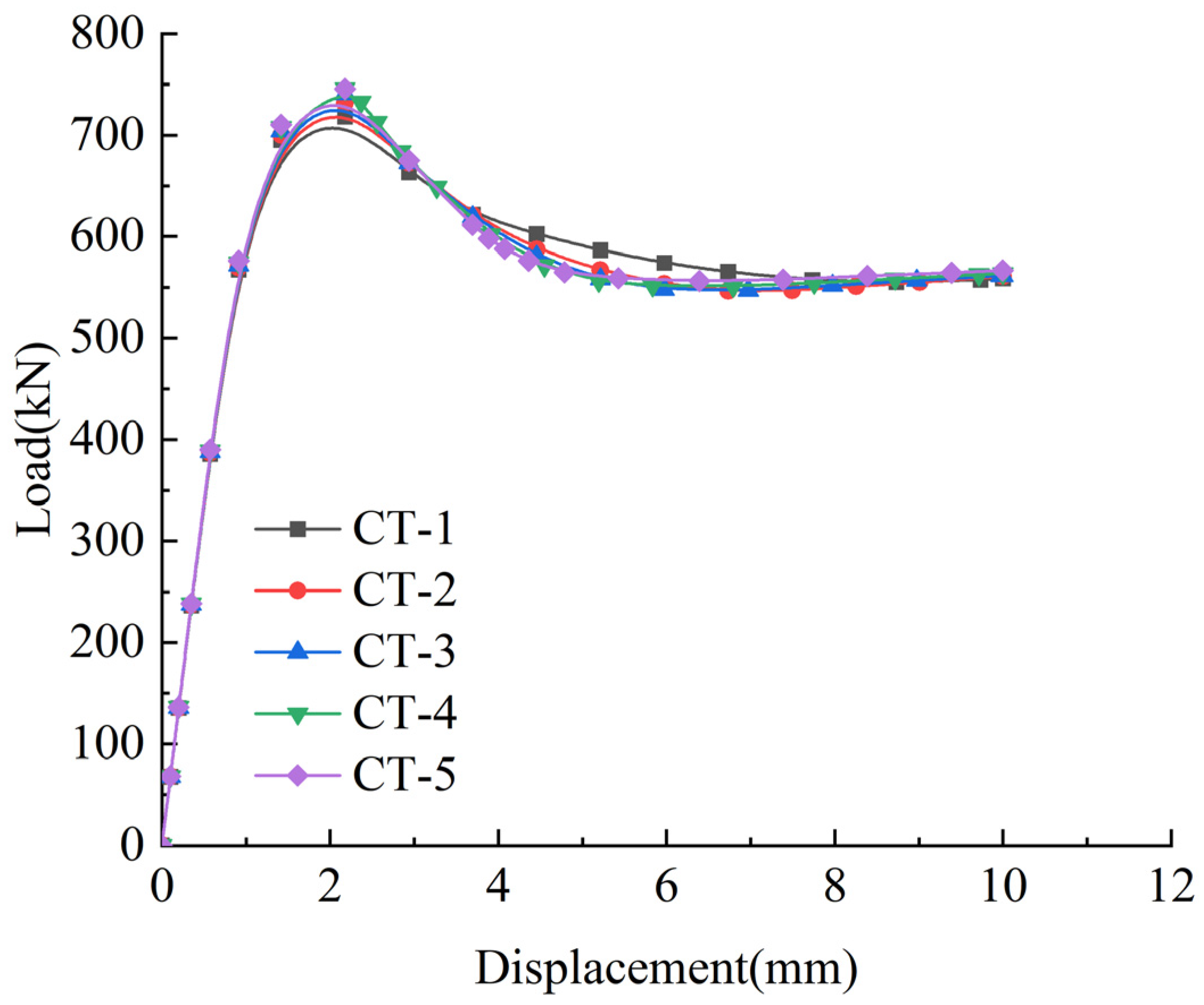
Figure 13 illustrates the load–displacement curves of specimens with varying casing thicknesses. For specimens CT-1 to CT-5, under a constant opening ratio, the load–displacement curves exhibited similar growth rates during the elastic stage, showing no sensitivity to changes in casing thickness. However, upon entering the elastoplastic stage, the curves diverged significantly. Specimen CT-1 achieved a peak load of 718.3 kN, while specimens CT-2 to CT-5 demonstrated progressive increases in peak load by 1.9%, 3.1%, 3.8%, and 3.77%, respectively, compared to CT-1. The experimental results confirmed a proportional relationship between the casing thickness and ultimate load capacity. However, when the casing thickness exceeded 2 mm (CT-4) and 2.5 mm (CT-5), the improvements in load-bearing capacity became statistically insignificant, with incremental gains of less than 0.5%.
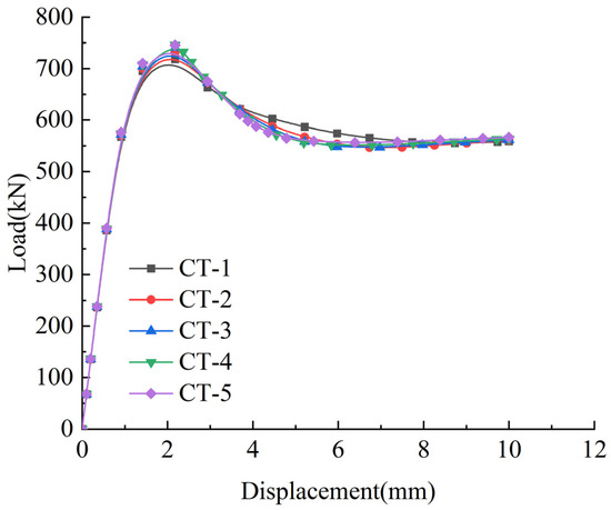
Figure 13.
Load–displacement curves corresponding to different casing thicknesses.
Table 10 presents the ductility coefficients (μ) of specimens with varying casing thicknesses. The ductility coefficients exhibit an inverse correlation with the casing thickness. Specimen CT-1 achieved the highest ductility coefficient of 2.39, while CT-5 showed a 25.5% reduction, with a ductility coefficient of 1.78. Under axial compression, increased casing thickness in the core area enhances the global load-bearing capacity but simultaneously reduces the ductility coefficients, accompanied by a decrease in overall deformation capacity (ranging from 18% to 26% across specimens).
Table 10.
Ductility coefficients of specimens with different casing thicknesses.
5.2. Bolt Preload
The influence of bolt preloading in the core area on the compressive behavior of concrete columns was investigated through finite element modeling using ABAQUS software. Based on the validated modeling parameters from Section 4, four specimen groups (PL-1 to PL-4) with varying bolt preloads were designed, maintaining the same cross-sectional dimensions as the ZY14 and ZY22 prototype columns. The key design parameters are detailed in Table 11.
Table 11.
Design parameters for specimens with different bolt preloads.
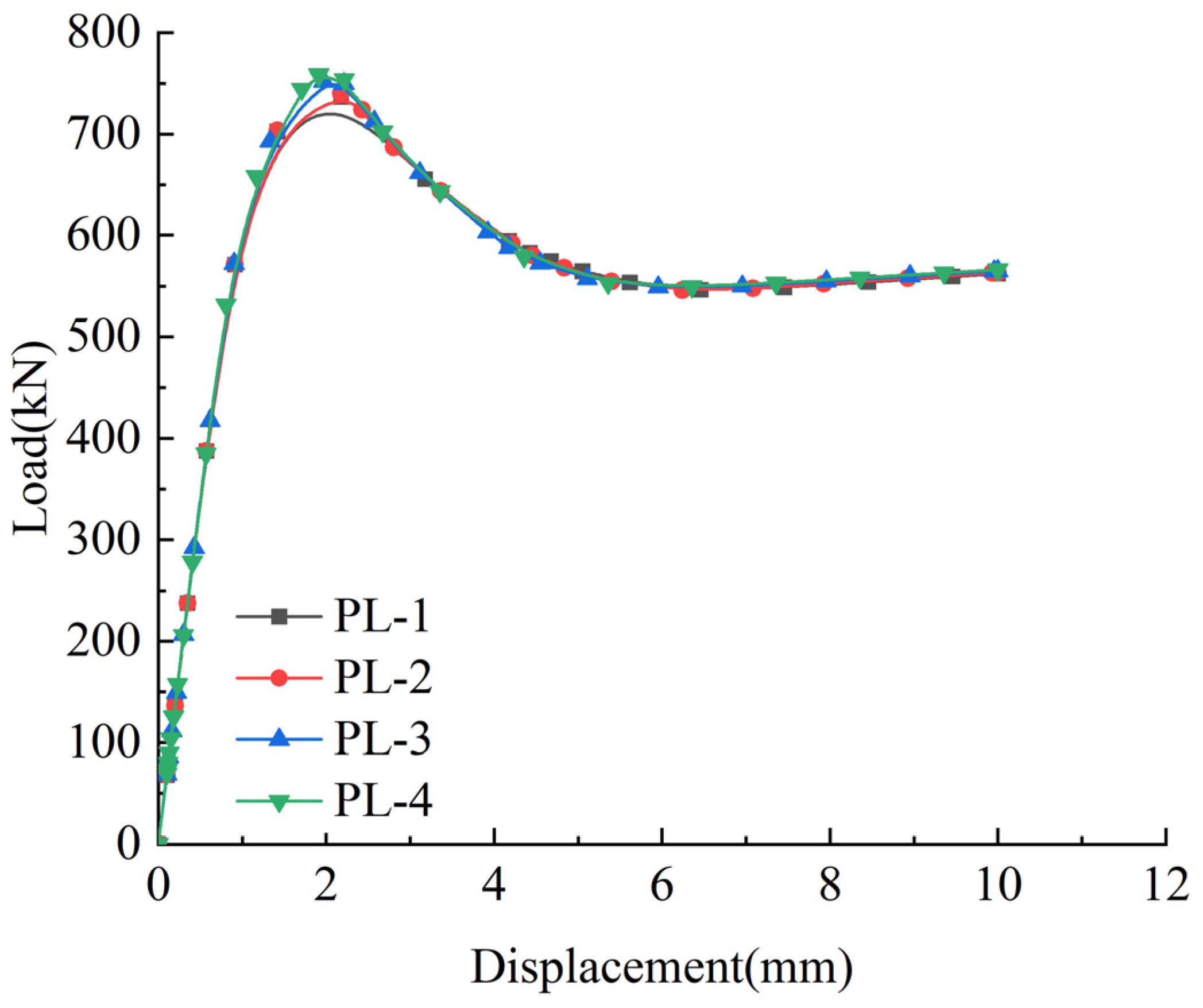
Figure 14 illustrates the load–displacement curves of specimens with varying bolt preloads. The load–displacement curves of specimens PL-1 to PL-4 exhibit similar trends during both the elastic and elastoplastic stages. Specimen PL-1 achieves a peak load of 736.9 kN, while specimens PL-2 to PL-4 demonstrate gradual increases in peak load capacity by 0.46%, 1.74%, and 2.96%, respectively, compared to PL-1. Although the load–displacement curves of the four specimens are nearly identical in shape, the peak load shows a gradual increase with higher bolt preloads.
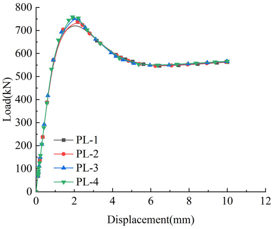
Figure 14.
Load–displacement curves corresponding to different bolt preloads.
Table 12 presents the ductility coefficients (μ) of specimens with varying bolt preloads. The application of bolt preloads in the core region significantly influences the ductility coefficients of specimens PL-1 to PL-4. Specimen PL-1 exhibits the highest ductility coefficient of 2.32, while PL-4 shows the lowest value of 1.76, representing a 24.1% reduction compared to PL-1. Under axial compression, increasing the bolt preloads in the core region enhances the overall load-bearing capacity of the specimens. However, it also reduces the ductility coefficients, leading to smaller overall deformations.
Table 12.
Ductility coefficients of specimens with different bolt preloads.
6. Calculation of Load Capacity
A comparison between the experimental results and finite element simulations for the specimens with opening ratios of 14%, 22%, and 26% revealed that the discrepancies in bearing capacity between the experimental and simulation outcomes were relatively small for opening ratios of 14% and 22%. Additionally, the specimen with an opening ratio of 26% exhibited the highest strength. Based on these findings, it is reasonable to use both the experimental data and finite element analysis results to derive a formula for the bearing capacity of precast concrete columns with openings, specifically for opening ratios under 25%. The formulas for calculating the bearing capacity are presented in Equations (2)–(4).
where represents the theoretically calculated bearing capacity, is the concrete correction factor of the precast column, refers to the compressive strength of the concrete cube according to the experimental result, denotes the effective area of the cross-section, represents the yield strength of the reinforcement, is the cross-sectional area of the reinforcement, is the cross-sectional area of the column, represents the opening ratio, and and indicate the stresses at the center and edge positions of the cross-section, respectively.
To evaluate the accuracy of the newly proposed formula, Table 13 compares the experimental bearing capacity with the theoretical bearing capacity for each specimen, including the ZY14 and ZY22 specimens. For instance, the ZY14 specimen exhibited an experimental bearing capacity of 659.67 kN and a theoretical bearing capacity of 701 kN, yielding a ratio of 0.94. Similarly, the ZY22 specimen showed an experimental bearing capacity of 716.67 kN and a theoretical bearing capacity of 734 kN, resulting in a ratio of 0.98.
Table 13.
Bearing capacity comparison of experimental and theoretical outcomes.
The average ratio of experimental to theoretical bearing capacity across all specimens was 0.96, with a variation coefficient of only 0.03%. The proposed formula was observed to provide highly accurate predictions of the bearing capacity for precast concrete columns with openings, confirming its applicability and reliability for engineering applications. The low variation and high accuracy indicate that the formula can be confidently applied to the design and evaluation of precast concrete columns with openings, particularly for opening ratios below 25%.
7. Conclusions
The failure mechanism of axially loaded precast columns with openings in the core area of the joints was investigated through static load tests and a finite element analysis. The main conclusions are as follows:
- (1)
- The load–displacement curves of specimens ZY14 and ZY22 exhibited distinct elastic and elastoplastic phases. As the axial loading increased, cracks initiated and propagated in the concrete within the upper or lower non-encrypted zones of the column, ultimately leading to the failure of the entire precast column.
- (2)
- The opening ratio significantly influenced both the peak load and ductility coefficient of the specimens. Specimen ZY22 exhibited an 8.6% higher peak load and a 4.8% lower axial displacement compared to specimen ZY14, with its ductility coefficient exceeding that of specimen ZY14 by 12.9%. Additionally, the presence of casings and transverse reinforcement in the core area indicated that the load-bearing capacity of the axially compressed precast concrete columns was primarily determined by the concrete in the non-encrypted zones.
- (3)
- A finite element model of the precast columns was developed using ABAQUS software, demonstrating excellent agreement between the simulation results and experimental data. For specimens ZY14 and ZY22, the discrepancies between the experimental and simulated peak loads were below 10%, with the corresponding axial displacement errors also being under 10%, confirming the accuracy of the finite element model.
- (4)
- Non-linear data fitting was performed on both the experimental data and parametric simulation results. Correction coefficients were introduced to derive axial compressive load capacity equations applicable to precast concrete columns with opening ratios below 25%.
Funding
This research was funded by Anhui Housing and Urban-Rural Construction Science and Technology Project grant number 2023-YF127, National Key Research & Development Program of China grant number 2016YFC0701500 and The Natural Science Major Research Program Project of Anhui Universities grant number 2024AH040037.
Conflicts of Interest
Authors Yaya Zhou and Junlong Ren were employed by the company Anhui Construction Engineering SanJian Group Co., Ltd. The remaining authors declare that the research was conducted in the absence of any commercial or financial relationships that could be construed as a potential conflict of interest.
References
- Minunno, R.; O’Grady, T.; Morrison, G.; Gruner, R.L.; Colling, M. Strategies for Applying the Circular Economy to Prefabricated Buildings. Buildings 2018, 8, 125. [Google Scholar] [CrossRef]
- Navaratnam, S.; Ngo, T.; Gunawardena, T.; Henderson, D. Performance review of prefabricated building systems and future research in Australia. Buildings 2019, 9, 38. [Google Scholar] [CrossRef]
- Lawson, R.M.; Ogden, R.G. Sustainability and Process Benefits of Modular Constructio. In Proceedings of the 18th CIB World Build Congress, Salford, UK, 10–13 May 2010; pp. 38–51. [Google Scholar]
- Lawson, R.M.; Ogden, R.; Bergin, R. Application of Modular Construction in High-Rise Buildings. J. Archit. Eng. 2012, 18, 148–154. [Google Scholar]
- Lu, N. The Current Use of Offsite Construction Techniques in the United States Construction Industry. In Proceedings of the Construction Research Congress, Seattle, WA, USA, 5–7 April 2009. [Google Scholar]
- Li, X.X.; Li, G.L. Exploration of modular build of architectural space. Appl. Mech. Mater. 2013, 357, 338–344. [Google Scholar]
- Yuan, Z.H.; Sun, C.; Wang, Y.W. Design for Manufacture and Assembly-oriented parametric design of prefabricated buildings. Autom. Constr. 2018, 88, 13–22. [Google Scholar]
- Chang, Y.; Li, X.D.; Masanet, E.; Zhang, L.; Huang, Z.; Ries, R. Unlocking the green opportunity for prefabricated buildings and construction in China. Resour. Conserv. Recycl. 2018, 139, 259–261. [Google Scholar]
- Nzabonimpa, J.D.; Hong, W.H.; Park, S.C. Experimental investigation of dry mechanical beam-column joints for precast concrete based frames. Struct. Des. Tall Spec. Build. 2017, 26, 1302. [Google Scholar]
- Liu, X.C.; He, X.N.; Zhang, A.L.; Tian, C.; Zhang, X.; Tan, Y. Design and specification compilation of a modular-prefabricated high-rise steel frame structure with diagonal braces part II: Elastic-plastic time-history analysis and joint design. Struct. Des. Tall Spec. Build. 2018, 27, 1414. [Google Scholar] [CrossRef]
- Choi, H.; Choi, Y.; Choi, C.S. Development and testing of precast concrete beam-to-column connections. Eng. Struct. 2013, 56, 1820–1835. [Google Scholar] [CrossRef]
- Sezen, H.; Whittaker, A.S. Seismic Performance of Industrial Facilities Affected by the 1999 Turkey Earthquake. J. Perform. Constr. Facil. 2006, 20, 28–36. [Google Scholar]
- Elsanadedy, H.M.; Al-Salloum, Y.A.; Alrubaidi, M.A.; Almusallam, T.H.; Siddiqui, N.A.; Abbas, H. Upgrading of precast RC beam-column joints using innovative FRP/steel hybrid technique for progressive collapse prevention. Constr. Build. Mater. 2021, 268, 121130. [Google Scholar]
- Wang, L.K.; Zhou, Y.; Shi, W.X. Seismic Response Control of a Nonlinear Tall Building Under Mainshock–Aftershock Sequences Using Semi-Active Tuned Mass Damper. Int. J. Struct. Stab. Dyn. 2023, 16, 2350018. [Google Scholar] [CrossRef]
- Xu, C.X.; Guo, C.; Xu, Q.Q.; Yang, Z. The global collapse resistance capacity of a seismic-damaged SRC frame strengthened with an enveloped steel jacket. Structures 2021, 33, 3433–3442. [Google Scholar]
- Belleri, A.; Brunesi, E.; Nascimbene, R.; Pagani, M.; Riva, P. Seismic Performance of Precast Industrial Facilities Following Major Earthquakes in the Italian Territory. J. Perform. Constr. Facil. 2015, 29, 04014135. [Google Scholar] [CrossRef]
- Brunesi, E.; Nascimbene, R.; Peloso, S. Evaluation of the Seismic Response of Precast Wall Connections: Experimental Observations and Numerical Modeling. J. Earthq. Eng. 2018, 24, 1057–1082. [Google Scholar] [CrossRef]
- Brunesi, E.; Peloso, S.; Pinho, R.; Nascimbene, R. Shake-Table Testing of a Full-Scale Two-Story Precast Wall-Slab-Wall Structure. Earthq. Spectra 2019, 35, 1583–1609. [Google Scholar] [CrossRef]
- Brunesi, E.; Peloso, S.; Pinho, R.; Nascimbene, R. Cyclic tensile testing of a three-way panel connection for precast wall-slab-wall structures. Struct. Concr. 2019, 20, 1307–1315. [Google Scholar] [CrossRef]
- Ravasini, S.; Bellett, B.; Brunes, E.; Nascimbene, R.; Parisi, F. Robustness-oriented conceptual design of precast concrete frame structures. In Proceedings of the International Fib Symposium on the Conceptual Design of Structures, Solothurn, Switzerland, 16–18 September 2021. [Google Scholar]
- Qiao, M.X.; Ma, Y.X.; Fung, T.C.; Tan, K.H. Seismic performance of PC beam-to-CECFST column joints with novel wet connections. Eng. Struct. 2025, 322, 119024. [Google Scholar]
- Balinen, H.; Jagarapu, D.C.K.; Eluru, A. Analysis of dry and wet connections in precast beam-column joint using ABAQUS software. Mater. Today Proc. 2020, 33, 287–295. [Google Scholar] [CrossRef]
- Bao, Y.T.; Tan, K.H. Performance of precast concrete beam-column joint with a hidden corbel under progressive collapse scenarios. Eng. Struct. 2022, 267, 114679. [Google Scholar] [CrossRef]
- Guan, D.Z.; Jiang, C.; Guo, Z.X.; Ge, H.B. Development and Seismic Behavior of Precast Concrete Beam-to-Column Connections. J. Earthq. Eng. 2016, 22, 234–256. [Google Scholar]
- Breccolotti, M.; Gentile, S.; Tommasini, M.; Materazzi, A.L.; Bonfigli, M.F.; Pasqualini, B.; Colone, V.; Gianesini, M. Beam-column joints in continuous RC frames: Comparison between cast-in-situ and precast solutions. Eng. Struct. 2016, 127, 129–144. [Google Scholar]
- ISO 20887; Sustainability in Buildings and Civil Engineering Works—Design for Disassembly and Adaptability-Principles, Requirements and Guidance. International Organization for Standardization: Geneva, Switzerland, 2020.
- Aninthaneni, P.K.; Dhakal, R.P.; Marshall, J. Experimental investigation of “dry” jointed precast concrete frame sub-assemblies with steel angle and tube connections. Bull. Earthq. Eng. 2020, 18, 3659–3681. [Google Scholar]
- Gardner, A.P.; Goldsworthy, H.M. Experimental investigation of the stiffness of critical components in a moment-resisting composite connection. J. Constr. Steel Res. 2018, 61, 709–726. [Google Scholar]
- Ertas, O.; Ozden, S.; Ozturan, T. Ductile Connections in Precast Concrete Moment Resisting Frames. PCI J. 2006, 3, 66–76. [Google Scholar] [CrossRef]
- Ma, W.; Li, Y.; Ding, K.W.; Cheng, B.; Liu, J.; Hao, J.; Tam, V.W.Y. Mechanical Properties of New Dry-Type Beam-Column Bolt Connection Joint. Sustainbility 2019, 11, 3348. [Google Scholar]
- Liu, Y.B.; Guo, Z.; Ding, J.H.; Wang, X.; Liu, Y. Experimental study on seismic behaviour of plug-in assembly concrete beam-column connections. Eng. Struct. 2020, 221, 111049. [Google Scholar] [CrossRef]
- Ding, K.W.; Ye, Y.; Ma, W. Seismic performance of precast concrete beam-column joint based on the bolt connection. Eng. Struct. 2021, 232, 111884. [Google Scholar]
- Zhang, Y.; Ma, W.; Li, X.; Li, K. Experimental Research on Seismic Behavior of Haunched Concrete Beam-Column Joint Based on the Bolt Connection. Sustainability 2022, 14, 15644. [Google Scholar] [CrossRef]
- Liu, X.C.; Liu, Y.K.; Chen, X.S. Axial compression behavior of prefabricated cruciform-section thin-concrete-encased steel short column. J. Constr. Steel Res. 2024, 217, 108640. [Google Scholar]
- Tao, Z.; Hasan, M.M.; Han, D.J.; Qin, Q.D. Study of the Axial Compressive Behaviour of Cross-Shaped CFST and ST Columns with Inner Changes. Buildings 2023, 13, 423. [Google Scholar] [CrossRef]
- Han, D.J.; Tao, Z.; Ghafar, W.A.; Hasan, M.M. Experimental Study on the Seismic Performance of L-Shaped CFST Columns in Different Combinations. Buildings 2023, 13, 2320. [Google Scholar] [CrossRef]
- Zhou, Y.J.; Wang, X.T.; Sun, H.R.; Chen, X.; Wang, T. Residual seismic performance for damaged RC frame based on beam-to-column joint subassemblies. Structures 2025, 71, 107980. [Google Scholar]
- Abrams, D. Scale relations for reinforced concrete beam–column joints. ACI Struct. J. 1987, 84, 502–512. [Google Scholar]
- Park, R. Evaluation of ductility of structures and structural assemblages from laboratory testing. Bull. N. Z. Soc. Earthq. Eng. 1989, 22, 155–166. [Google Scholar]
- GB50010-2010; Code for Design of Concrete Structures. Architecture and Construction Press: Beijing, China, 2010.
- Wriggers, P. Computational Contact Mechanics. Comput. Mech. 2003, 32, 141. [Google Scholar] [CrossRef]
- Zhou, Y.; Chen, T.P.; Pei, Y.L.; Hwang, H.J. Static load test on progressive collapse resistance of fully assembled precast concrete frame structure. Eng. Struct. 2019, 200, 109719. [Google Scholar]


Disclaimer/Publisher’s Note: The statements, opinions and data contained in all publications are solely those of the individual author(s) and contributor(s) and not of MDPI and/or the editor(s). MDPI and/or the editor(s) disclaim responsibility for any injury to people or property resulting from any ideas, methods, instructions or products referred to in the content. |
© 2025 by the authors. Licensee MDPI, Basel, Switzerland. This article is an open access article distributed under the terms and conditions of the Creative Commons Attribution (CC BY) license (https://creativecommons.org/licenses/by/4.0/).