Abstract
The primary objective of this study is to establish an innovative theoretical framework for analyzing the behavior of an end-bearing pile-supported embankment. This proposed methodology extensively investigates various aspects, including the characteristics of relative slip at the interface between the pile and soil, the distinctive non-uniform deformation patterns typically observed in soft soils, and the substantial influence of pile–soil interaction on the evolution of soil arching phenomena. To precisely capture the frictional relationship and relative displacement within the pile–soil system, we introduce an enhanced ideal elastic-plastic model. Additionally, a deformation function is incorporated to simulate the non-uniform deformation of soft soils, and an improved soil arching model is developed to assess its impact on the overall behavior. The analytical solution is derived through the implementation of a stress and volume deformation continuity condition, and its validity is effectively demonstrated through numerical simulations. The results indicate that under the load of the embankment, relative slip at the pile–soil contact surface is a significant phenomenon and should not be neglected in theoretical calculations. The relative displacement between the pile and soil initially exhibits a linear relationship with depth, and later follows a quadratic function as depth increases.
1. Introduction
Piles are extensively utilized to provide support to embankments constructed on soft soils, aiming to enhance bearing capacity and mitigate total and differential settlement [1,2,3,4]. In comparison to alternative methods for treating soft soils (e.g., lightweight materials, excavation and replacement, preloading, and vertical drainage) [5,6,7,8,9,10,11], pile-supported embankments offer notable advantages, including shorter construction times (eliminating the need for the consolidation stage) and cost-effectiveness. Pile-supported embankment systems comprise embankments, piles, and soft soils. Under the load of the embankment, differential settlement arises between the pile and the surrounding soils due to their differing stiffness. Specifically, the soil between the piles settles downward relative to the piles. The relative displacement results in shear stress along the potential slip plane, thereby increasing the load transferred from the embankment to the pile. Further analysis shows that the change in the load transfer path, caused by relative displacement, leads to principal stress rotation and fabric anisotropy [12,13,14]. This phenomenon, known as the soil arching effect [15,16], is one of the main load—transfer mechanisms in pile-supported embankments. This phenomenon is known as the soil arching effect [15,16], which represents one of the key load-transfer mechanisms in pile-supported embankments. Considerable efforts have been devoted to developing a suitable model that captures the transfer mechanisms of the soil arching effect [15]. Terzaghi (1943) [17] initially proposed a soil column model, assuming that friction occurs in the vertical planes along the edge of the pile. Guido et al. (1987) [18] proposed a regular pyramid soil arching model based on tests performed on a multi-layered geogrid-reinforced granular mattress. Building upon this, Collin (2004) [19] further improved the regular pyramid model by assuming a dip angle of 45 degrees on the side of a regular pyramid and requiring the geo-reinforced material to have at least three layers. Hewlett and Randolph (1988) [20] proposed a hemispherical soil arching model assuming that the arch crown or arch feet are in an ultimate stress state. Kempfert et al. (1997) [21] put forth a multi-shell arching theory, and Van Eekelen et al. (2013) [22] proposed a concentric arches model based on numerous model tests. Chen (2008) [23] adopted a cylindrical unit cell model to analyze the soil arching effect, assuming that the embankment is composed of an inner cylinder and an outer hollow cylinder. However, various soil arching models rely on diverse assumptions and formulas. Additionally, several studies have demonstrated significant inconsistencies in the results obtained from these models [24,25,26]. This discrepancy arises because existing models lack deep insight into the evolving process of the soil arching structure in pile-supported embankments. Each soil arching model merely represents a specific point or a limited segment of the complete ground reaction curve, depicting the gradual development of soil arching with relative displacement [27], while disregarding the effect of relative displacement [28].
The pile–soil interaction is another significant load-transfer mechanism in pile-supported embankments. However, little research has addressed this interaction in relation to soil arching issues, primarily due to the problem’s complexity. Alamgir (1996) [29] proposed an analytical model considering the non-uniform settlement of soft soils, assuming that the vertical stress was equal at the pile-top plane and neglecting the relative slip on the pile–soil interface. Nonetheless, these assumptions were unrealistic for pile-supported embankments and underestimated the role of the pile. Chen (2008) [23] presented a theoretical solution by assuming uniform ambient soils and a specific distribution pattern of side friction. Zhuang (2014) [5] considered the pile–soil interaction based on a simplified equation of one-dimensional compression of the subsoil. Zhao and Zhou (2017) [30] incorporated the soil arching effect based on Alamgir’s model, but they did not consider the relative slip between piles and soils at the interface. Since the load-transfer mechanism in pile-supported embankments combines the soil arching effect and the pile–soil interaction, it is not reasonable to separately analyze the relative sliding at the pile–soil interface and the non-uniform settlement of the soft soil. However, most studies did not consider both the soil arching effect and the pile–soil interaction, as indicated in Table 1.

Table 1.
Summary of the literature related to pile supported-embankment.
In light of these limitations, the authors propose a theoretical method that accounts for the non-uniform deformation of soft soil, the pile–soil interaction, and the soil arching effect. Building on Alamgir’s (1996) [29] vertical displacement function, the method considers the relative slip between the pile and the soil at the interface using an improved ideal elastic-plastic model with shear stiffness that varies with normal stress. Additionally, an improved unit cell model incorporating a friction calibration coefficient is utilized to quantify the impact of relative displacement on the development of soil arching. The solution of the proposed method is achieved by integrating the deformation equation of the embankment with that of the composite foundation, ensuring the continuity of stress and volume. Moreover, the proposed method underwent verification through a numerical simulation conducted using FLAC3D 3.0.
2. Improved Ideal Elastic-Plastic Model
The composite foundation is an engineering solution developed to address the insufficient load-bearing capacity of natural foundations. The load transmission in a composite foundation is primarily governed by pile-side friction and pile-tip resistance. Friction is determined by the relative movement between the pile and the soil, whereas resistance is dictated by the strength of the underlying substratum. The mathematical relationship between friction and the relative displacement of the pile and soil is known as the load transfer function, which plays a crucial role in calculating the load transfer between piles and soils. Currently, two main methods have been proposed for determining the load transfer function: the analytical method, which simplifies the function into a specific equation, and the displacement coordination method, which derives the function through field measurements or laboratory tests [38]. Due to the time-consuming and expensive nature of in situ studies, extensive efforts have been devoted to laboratory model testing to investigate the soil-structure interaction, resulting in the establishment of various load transfer models. Kezdi (1957) [39] introduced the exponential curve model for the load transfer function. Richard (1975) [40] developed a stress–strain relation similar to the three-parameter model based on the Ramberg-Osgood model. Kraft (1981) [41] proposed the hyperbola model. Heydinger (1987) [42] took into account the settlement, consolidation, and loading effects of the pile, establishing a nonlinear relationship between friction and relative displacement using Richard’s model (1975) [40]. These aforementioned studies provided valuable insights into the load transfer mechanism; nevertheless, the mathematical expressions are complex, and obtaining the required parameters is challenging, limiting the wider adoption of these models in engineering practice. In contrast, the ideal elastic-plastic model is widely employed by researchers and engineers due to its simple mathematical expression, high usability, and conciseness [43,44,45,46,47,48,49].
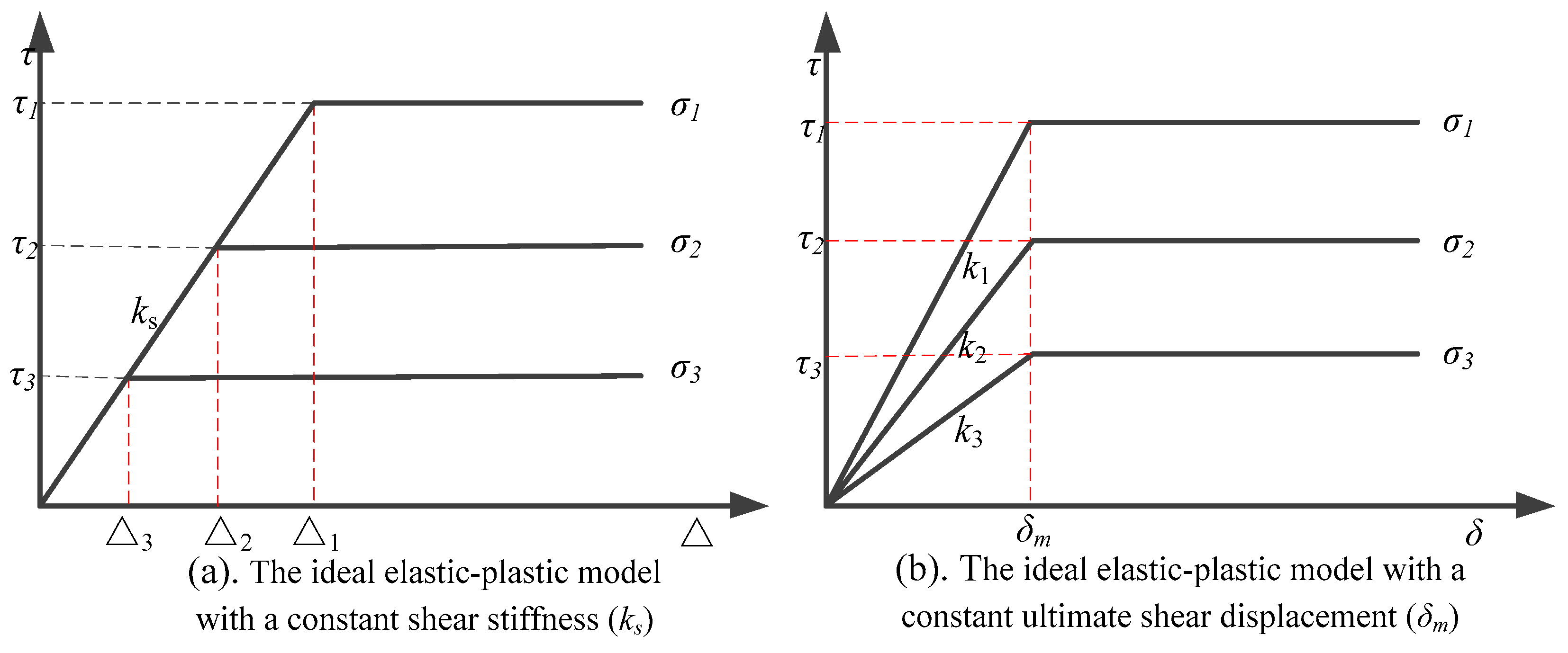
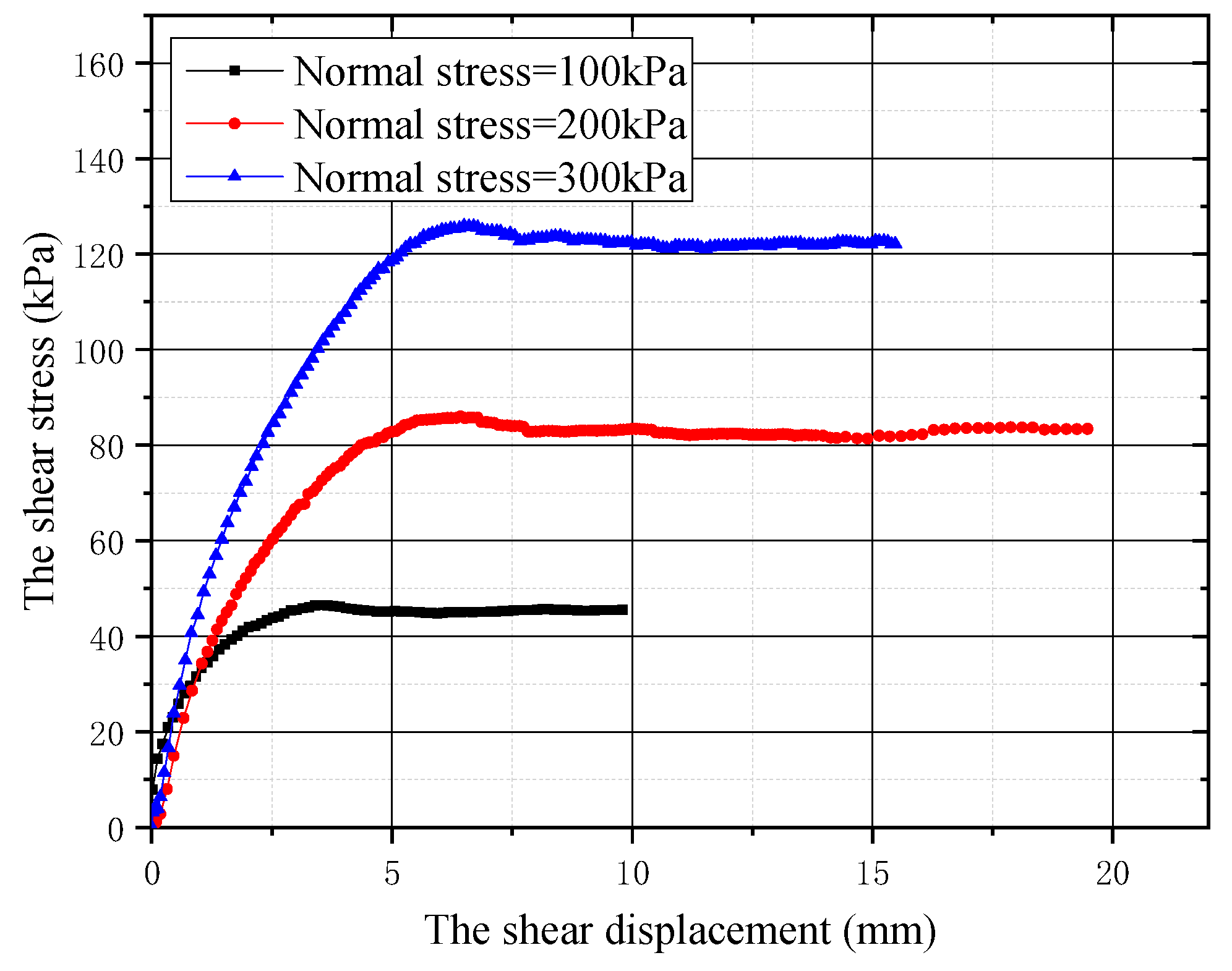
The ideal elastic-plastic model assumes a constant shear stiffness while the ultimate shear displacement varies with normal stress, as illustrated in Figure 1. Randolph and Wroth (1978) [50] proposed an empirical method for estimating shear stiffness. However, test results indicate that under identical material and contact surface conditions, the influence of normal stress on the ultimate shear displacement is significantly less pronounced compared to its impact on the shear yield stress. For instance, Reddy (2000) [51] performed shear tests on rigid piles and sandy soil, revealing that when the normal stress is 100 kPa and 150 kPa, the shear yield stress increases by 1.01 times and 2.01 times, respectively, in comparison to the shear yield stress at 50 kPa. However, the ultimate shear displacement only increases by 0.34 times and 0.10 times, respectively. Another study by Jesus (2007) [52] conducted a large-scale direct shear test on the interface between concrete and sand. The results indicated that at normal stress levels of 33 kPa, 102 kPa, and 274 kPa, the shear stress increased by 1.14 times, 5.07 times, and 15.79 times, respectively, in comparison to the shear stress at 15 kPa. However, the ultimate shear displacement only increased by 0.46 times, 0.84 times, and 1.46 times. In order to validate the aforementioned conclusion, the researcher conducted a direct shear test on the sand-concrete interface (Figure 2), yielding consistent results.
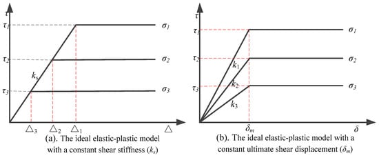
Figure 1.
The load transfer model on the pile–soil interface.

Figure 2.
The direct shear test between the sand and concrete.
The experimental results indicate that the modified ideal elastoplastic model, which assumes a constant ultimate shear displacement and variable shear stiffness, better reflects engineering reality than the ideal elastoplastic model which assumes constant shear stiffness and variable ultimate shear displacement. To account for the size effect and facilitate literature comparisons, the normalized ultimate shear displacement, δm, is introduced to explore the relationship between relative displacement and shear stress. Figure 1 illustrates the shear stiffness of the improved ideal elastic-plastic model, incorporating a constant ultimate shear displacement, expressed as ki = τui/δm. Here, τui represents the ultimate shear stress at a normal stress of σi, and δm denotes the normalized ultimate shear displacement.
3. Mathematical Model
3.1. Analytical Model
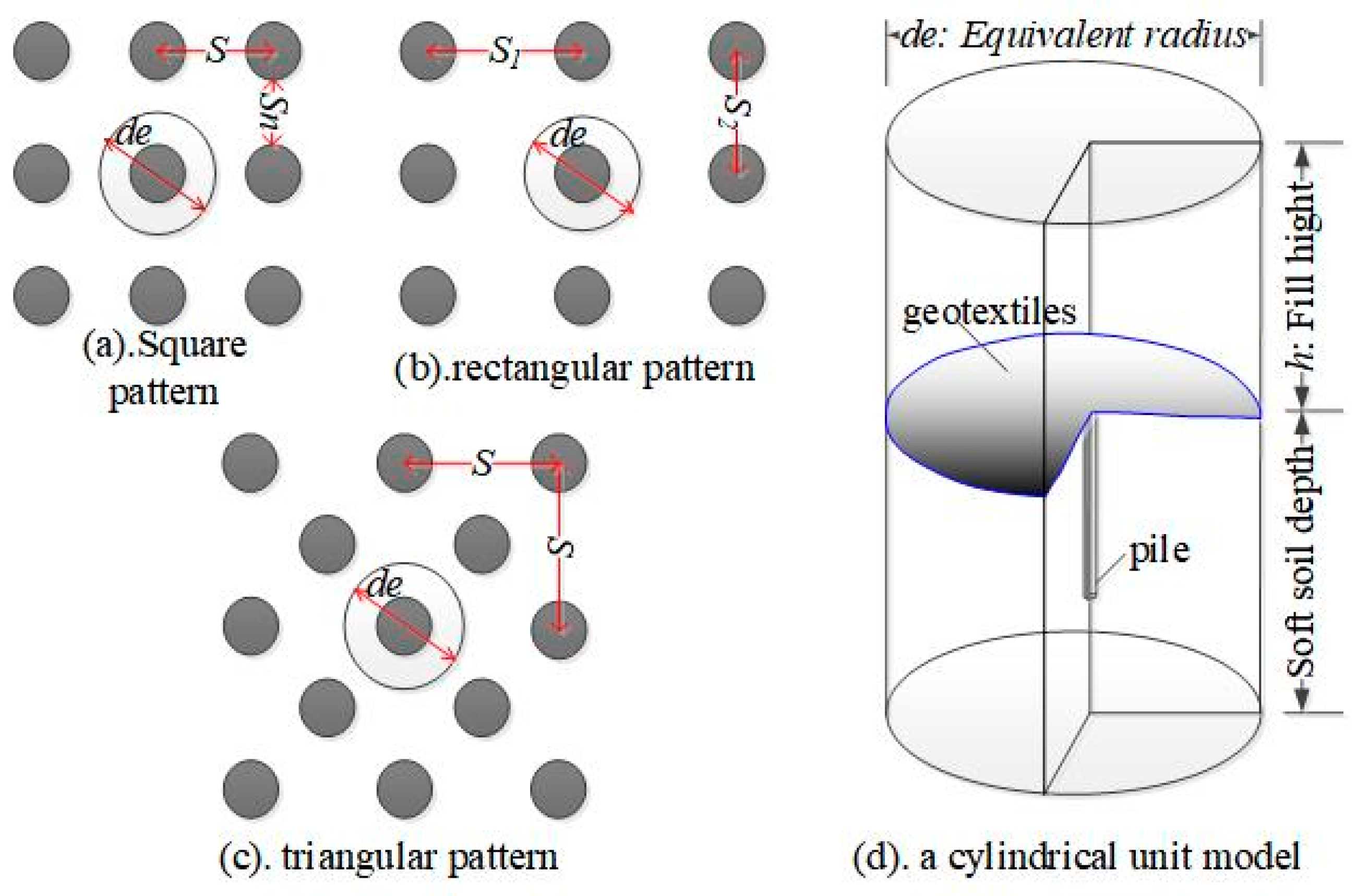
The unit cell model is a widely adopted and simplified approach to analyzing composite foundations, offering valuable insights into the stress and deformation properties of piles [53]. As depicted in Figure 3 [23], the basic model configuration comprises the pile, ambient soil, geotextiles, and embankment. This current study aims to develop a more practical theoretical model for analyzing the behavior of pile-supported embankments. To address the load distribution in terminating pile-supported embankments, the model is divided into two distinct zones: the embankment zone and the reinforcement zone, each governed by specific load transfer mechanisms of pile-supported embankments.
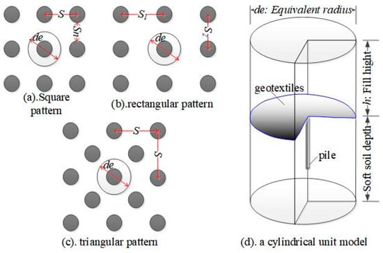
Figure 3.
The universal simplified model for composite foundation calculation.
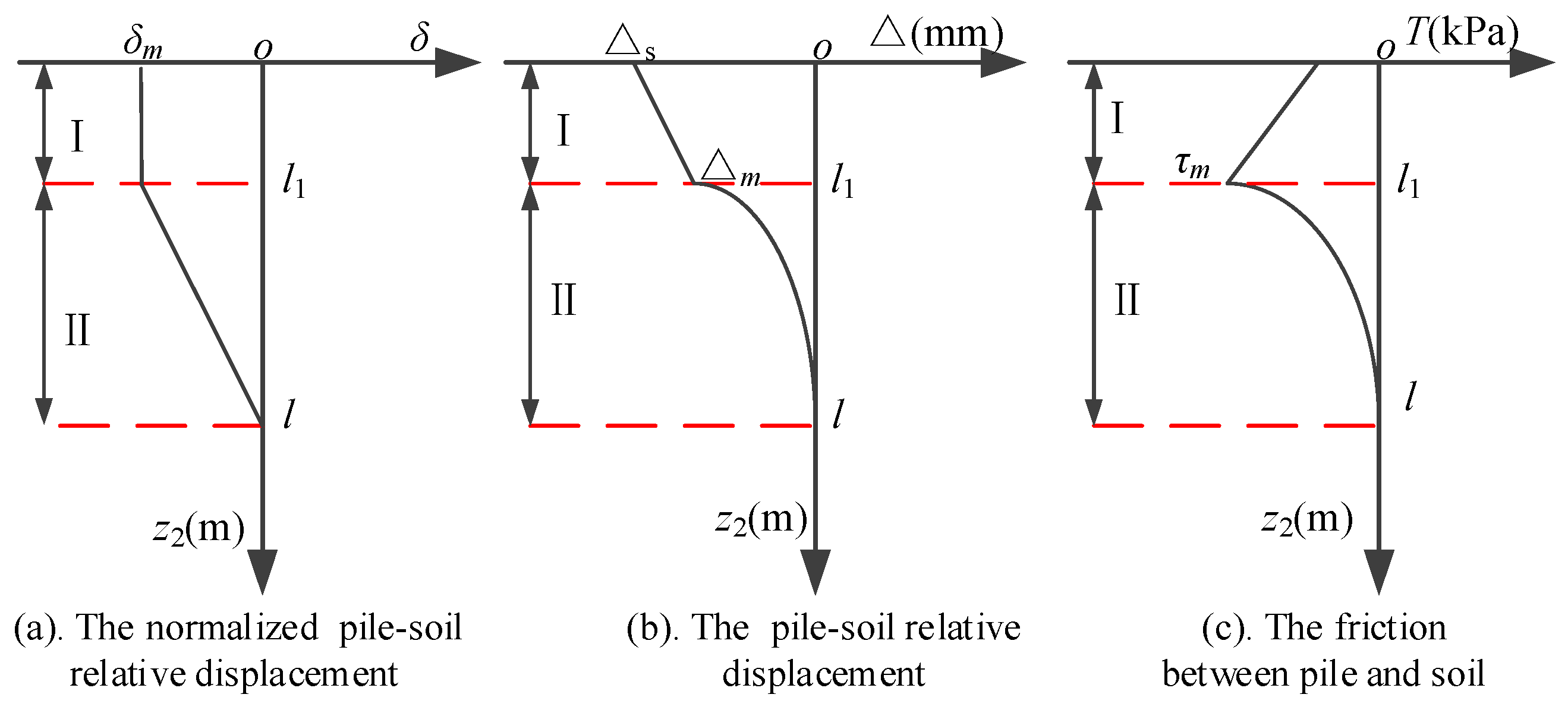
Furthermore, the embankment itself is subdivided into two segments: the inner cylinder, characterized by a diameter of dc (corresponding to the diameter of the pile or pile cap), and the outer hollow cylinder, defined by outer diameter de and inner diameter of dc. Notably, the load in a composite foundation of terminating pile-supported embankments is shared between the pile and the surrounding soil. Hence, the model’s reinforcement zone is further partitioned into the plastic deformation zone (labeled as Zone I in Figure 4) and the elastic deformation zone (labeled as Zone II in Figure 4). This division is based on the specific deformation characteristics observed at the pile–soil interface, and it aids in accurately analyzing the termination behavior of pile-supported embankments.
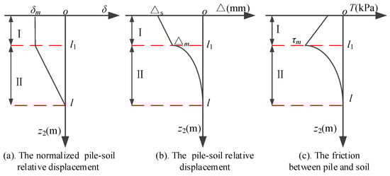
Figure 4.
Transfer model of pile–soil interface.
3.2. Load Transfer in the Embankment
The stiffness disparity between piles and soils generally leads to greater settlement of ambient soils compared to the piles themselves. Consequently, the fill in the outer hollow cylinder tends to slide downward relative to the fill in the inner cylinder section, resulting in friction at the interface between the two cylinders. Notably, this relative slippage is most prominent near the bottom of the embankment and gradually diminishes with decreasing embankment depth until it eventually comes to a halt at the level settlement plane.
The trend of friction fluctuation closely follows that of the relative movement between the outer and inner cylinders. Specifically, at the level settlement plane, where the relative movement reaches zero, there is no friction at the interface between the two cylinders. However, it has been observed that Chen and Zhao’s prior study [23,30] did not meet the frictionless criterion at the level settlement plane. To address this and to accurately account for the effect of relative displacement, an additional term denoted as β is introduced in the subsequent research. This term β varies linearly from 0 (representing the condition at the level settlement plane) to 1 (presumably at the top of the pile), thereby providing a comprehensive understanding of the friction behavior along the interface between the outer and inner cylinders.
A local coordinate system, as shown in Figure 5, is established for the analysis. To simplify the calculations and ensure clarity for readers to reproduce the model and obtain similar results, the following assumptions are made and explained in detail:
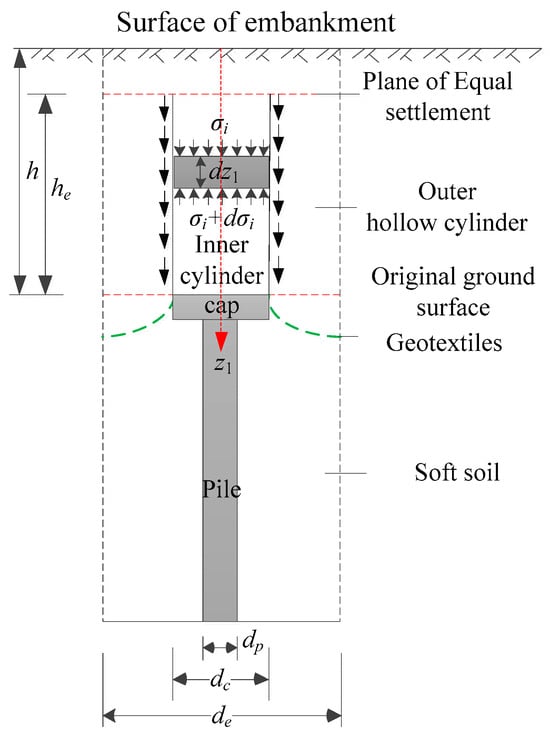
Figure 5.
Analytical model of the pile-supported embankment.
- The fill material is assumed to be homogeneous, isotropic, and non-cohesive. This means that the material properties are uniform throughout the volume and do not vary with direction. The material is characterized by the internal friction angle φe, the unit weight γe, and Young’s modulus Ee.
- It is assumed that the pile, soil, and embankment fill experience vertical compression only, with any lateral deformations being neglected. This assumption is made to focus on the primary load transfer mechanism in the system, which is vertical compression due to the weight of the embankment and applied loads.
The friction on the contact surface between the inner cylinder and the outer hollow cylinder can be expressed as:
where f is the friction between the inner cylinder and the outer hollow cylinder, β is the calibrating coefficient of the friction, z1 is the vertical distance from the calculation point to the surface of the embankment, σi(z1) is the vertical stress of the inner cylinder, k0 is the coefficient of static earth pressure, and φe is the internal friction angle of fill.
Considering the influence of relative displacement, the lateral pressure coefficient can be further expressed as:
where h stands for the height of the embankment, and he is the height of the equal settlement plane.
Figure 5 illustrates the analytical model of the pile-supported embankment. In the inner cylinder, we consider a unit element with a thickness of dz1 for analysis, while ignoring lateral displacements in line with assumption 2. The equilibrium of the unit element in the vertical direction can be expressed as follows:
where Ai is the cross-sectional area of the inner cylinder, γe is the unit weight of the fill, dc is the pile diameter or the pile cap.
When z1 = h − he, σi(z1) = γe (h − he). The integration of Equation (3) from h − he to z1 can be expressed as:
where T is the intermediate variables, T = 4 tan(φe)·k0/(dc·he). Erf is the error function.
The equilibrium of vertical stress in embankment requires that [23]:
where m represents the area ratio of the inner cylinder to the whole cylinder (m = dc2/de2), de is the effective reinforcement diameter of the pile, and σo(z1) stands for the vertical stress of the outer hollow cylinder.
According to the stress–strain relationship, the differential settlement at the bottom of the embankment can be formulated as follows:
3.3. Load Transfer Within Tensile Reinforcement
The tensioned membrane effect in the geosynthetic-reinforced pile-supported embankment occurs as a result of the tension induced by the load from the embankment, which mobilizes the tensile strength of the geosynthetic material. This effect plays a crucial role in shaping the development of soil arching and improving the transmission of load from the superstructure to the pile. To facilitate computational simplicity, the assumption is made that the force acting on the geosynthetic is distributed uniformly, and the deformation of the geosynthetic material follows a parabolic pattern [5].
The horizontal components of the tensile stress and the vertical stress acting on the geosynthetic satisfy the following equation.
where T is the horizontal component of the tensile stress, σr is the vertical stress acting on the geosynthetic, and δr is the maximum deflection of the geosynthetic.
The average strain of the geosynthetic can be expressed as:
The stress–strain relationship of geosynthetics can be expressed as:
where kg is the tensile stiffness of the geosynthetic.
Substituting Equations (7) and (8) into Equation (9):
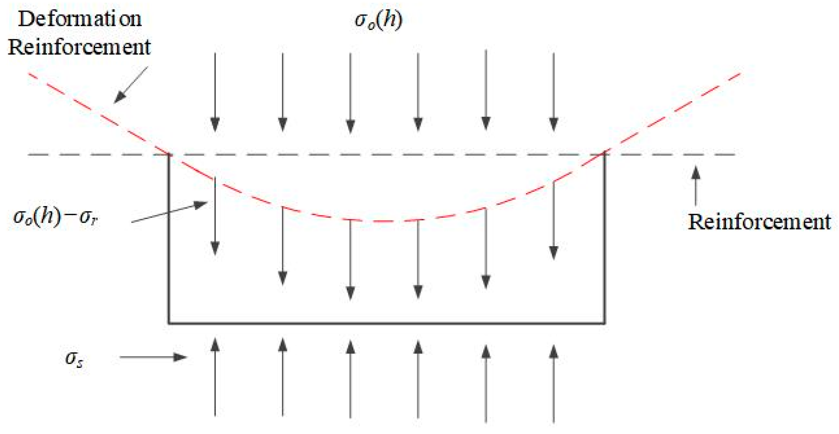
As shown in Figure 6 [5], the vertical stress carried by the soft soil can be determined.
where σs is the vertical stress carried by the subsoil, and σo(h) is the vertical stress of soil on the upper surface of geosynthetic.
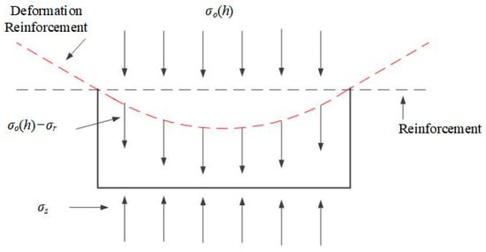
Figure 6.
Stress analysis of the element at the centerline between piles.
The proportion of the load carried by the pile is defined as the load-sharing ratio (n1), and the stress of the inner cylinder against the stress of the outer hollow cylinder at the bottom of the embankment is defined as the pile–soil stress ratio (n).
where Ao is the cross-sectional area of the outer hollow cylinder.
3.4. Load Transfer Within Reinforced Areas
In the context of flexible foundation situations, the load of the composite foundation is distributed between the pile and the surrounding soil. The distinct stiffness of the pile and the soil leads to differential settlement, causing uneven deformation of the soil between the piles [15,23]. To analyze this non-uniform soil deformation, Alamgir (1996) [29] developed a vertical displacement model, assuming no relative displacement at the pile–soil contact surface. However, the numerical analysis by Zhao et al. [30] revealed an obvious relative slide between the pile and the soil at the contact surfaces. To address this observed discrepancy, the author incorporated the relative slip between the pile and soil at the contact surface, resulting in an improved and more accurate model that better aids engineering practices for composite foundations under flexible foundation conditions.
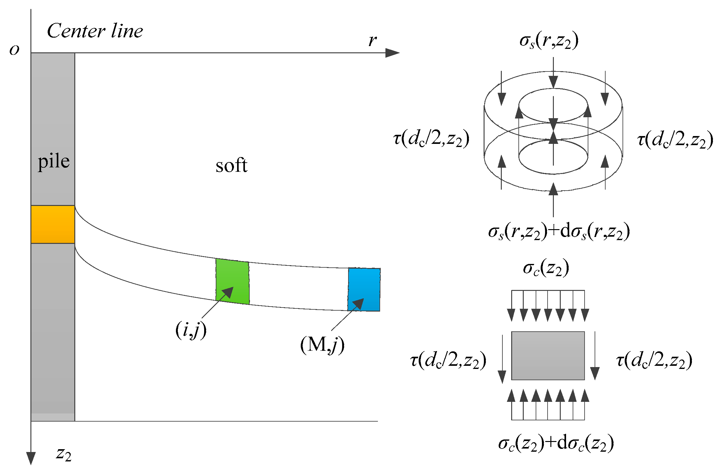
For computational convenience, a local coordinate system is established, as depicted in Figure 7 [29]. The improved model can be expressed as follows:
where r is the horizontal distance from the pile center to a point in the soil, w(r, z2) is the vertical deformation function of soft soil, wc(z2) is the vertical deformation of the pile at a depth of z2, αc(z2) and ατ(z2) are the function of z2, βc is the undetermined coefficients dependent on the boundary conditions.
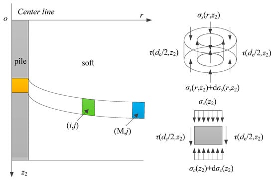
Figure 7.
Analytical model of soil between piles.
According to the shear deformation formula of elastic mechanics, the shear stress can be expressed as:
When r = de/2, τ(de/2, z2) = 0, βc can be express as:
When r = dc/2, τ(dc/2, z2) = 0, the friction between the pile and soil can be expressed as:
Equation (17) shows that the friction between the pile and the soil exhibits a linear relationship with αc(z2), where αc(z2) serves as the distribution function of friction on the contact surface.
In Figure 4a, it is evident that the relative displacement of the pile and soil in the plastic region exceeds the limiting shear displacement, while the relative displacement in the elastic region remains below the limiting shear displacement. To model this behavior, the study assumes that the normalized relative displacement (δ) varies linearly along the depth in the elastic region, whereas it remains constant (δm) in the plastic region. Consequently, the distribution function of the normalized relative displacement can be expressed as follows:
By integrating Equation (18) along the z2 direction, the distribution pattern of pile–soil relative displacement in the z2 direction can be obtained, which is depicted in Figure 4b. In-plane of the pile top, the relative displacement between the pile and soil can be expressed as:
It is known that the pile would be subject to downward friction due to the downward relative movement, as shown in Figure 4c. The βτ method [54] is introduced to calculate the limiting shear stress, and the distribution of friction along the depth can be expressed as:
where hd is the equivalent height of soil stress between piles, hd = σo/γe, γs is the unit weight of the soft soil.
Substituting Equation (17) into Equation (20), the distribution function of friction, αc(z2), can be expressed as:
Substituting r = dc/2 into Equation (14):
ατ(z2) can be regarded as the slip function of pile–soil interface.
As shown in Figure 7, taking a unit element with thickness of dz2 as the research object. The vertical stress equilibrium of a pile element at any depth can be expressed as:
Similarly, the vertical stress equilibrium of soil between piles at any position (r, z2) can be expressed as:
Substituting Equation (15) into Equation (25):
Substituting Equation (17) into Equation (26):
where R(r) is the intermediate variables, .
Substituting Equation (20) into Equations (24) and (27) and then integrating these equations.
where C1, C2, C3 and C4 are the integral constant, the value of C1, C2, C3 and C4 are obtained through the stress continuity condition.
Substituting Equations (21) and (23) into Equation (14), the displacement equation can be expressed as:
3.5. Solution
According to the volume continuity condition, the subsidence of the embankment at the plane of the pile top should be equal to the subsidence of the soil between piles at the same plane. The volumetric deformation of soft soil at the top plane of the pile can be expressed as:
where w(r, 0) is the settlement of soil between piles at (r, 0).
The sinking volume of the embankment can be calculated by the following formula.
In Equations (31) and (32), he represents the only unknown factor. Due to the highly nonlinear nature of these equations, it is not possible to directly express the unknown factors using simple formulas. To address this, an iterative method is employed to solve these equations. The process begins with an initial value assigned to he, which is then substituted into Equations (31) and (32), respectively. The calculations are iteratively repeated until Equation (31) equals Equation (32). Once this condition is met, the values of the other unknown factors can be obtained accordingly. This iterative approach allows for an approximate solution to the system of equations involving the unknown factor he.
4. Determining the Calculation Parameters
Before proceeding with the settlement calculation of pile-supported embankments using the proposed method, it is essential to determine the values of three critical parameters: the normalized limiting shear displacement (δm), the depth of the plastic deformation zone (l1), and the effective reinforcement depth (l0). The parameter δm is directly related to the properties of the soil, whereas l0 and l1 are associated with the geometric characteristics of the embankment. Given the limited existing literature on these parameters, numerical simulation methods are employed to explore and ascertain their appropriate values.
For this numerical analysis, the finite difference element (FDM) method is selected, recognized for its efficiency and widespread use in geotechnical engineering [55,56,57]. As shown in Figure 8, an axisymmetric model is created using FLAC3D 5.0, based on the concept of the cylindrical unit cell as utilized in the theoretical method. The piles are arranged in a square pattern (as depicted in Figure 3a) with a pile spacing of 1.8 m, and the length of the pile is equal to the depth of the soft soil, considering depths of 3 m, 4 m, 6 m, and 8 m. The embankment heights are set at 4 m and 5 m, respectively. In the axisymmetric model, vertical displacement is allowed at the vertical boundary while the bottom boundary is fixed in all directions. A tetrahedral mesh was used due to its adaptability to complex geometries. A total of 15,000 meshes were generated for the model.
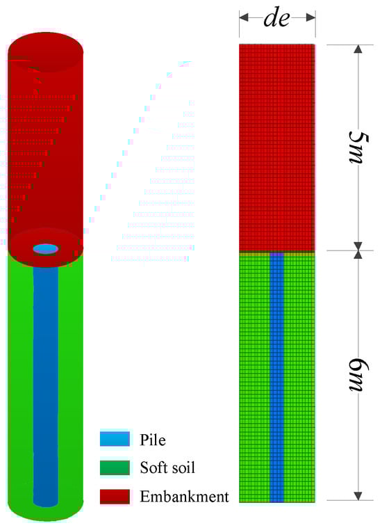
Figure 8.
The general view of the numerical model.
To simulate the behavior of the embankment fill and soft soil, the linearly elastic-perfectly plastic model and the Mohr-Coulomb yield criterion are employed. The pile is treated as a linear elastic material. Table 2 presents a summary of the material properties and geometric parameters utilized in this numerical analysis.
Table 2.
Geometry and material properties of the case study.
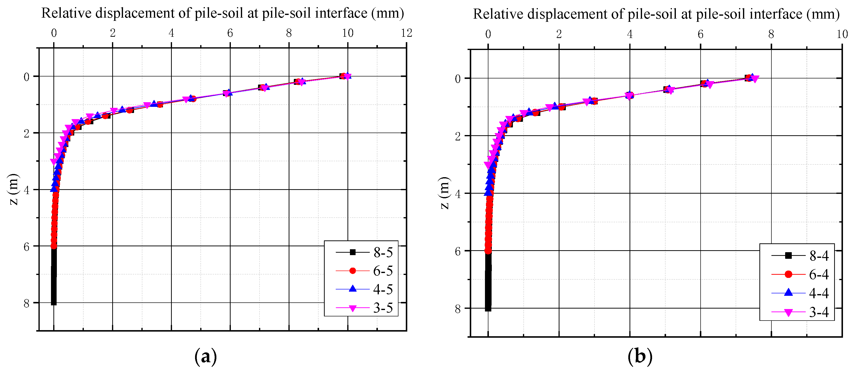
Figure 9 illustrates the variation in pile and soil relative displacement along the vertical direction. Remarkably, the relative displacement demonstrates a consistent trend along the depth, regardless of different pile lengths and embankment heights. The curve initially follows a linear relationship with the increase of z2 and subsequently takes the form of a quadratic function, aligning precisely with the hypothesis of the proposed method and providing validation for the accuracy of the theoretical approach.
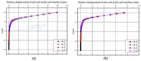
Figure 9.
The variation trend of pile–soil relative displacement with varying z. (a) the height of the embankment is 5 m. (b) the height of the embankment is 4 m.
Within Figure 9, a linear section is evident, and the differences between adjacent points are minimal. This linear portion corresponds to the plastic zone of pile–soil slip, as hypothesized in the theoretical method. As z2 increases, the differences between adjacent points progressively decrease. To streamline the calculation process points with a relative displacement difference of less than 0.1 mm between adjacent points are considered to have zero relative displacement between the pile and soil at that position. The numerical results support this assumption, and the cumulative settlement error remains below 0.5 mm.
Based on the numerical calculation results, the normalized limiting shear displacement (δm) is determined to be 0.006 in the theoretical calculation, representing the average value obtained from the numerical simulations (as shown in Table 3).
Table 3.
The summary of the δm.
5. Validation
Comparison with the Finite Difference Element (FDE) Model
In this section, we conduct two cases with different embankment heights to validate the reliability of the proposed method. In the first case, we consider a pile length (l) of 6 and an embankment height (h) of 4, with the depth of the plastic deformation zone (l1) set to 0.6 and the effective reinforcement depth (l0) to 1.6. For the second case, we use the same pile length (l) of 6 but with a higher embankment height (h) of 5, and adopt l1 = 1 and l0 = 2.
The geometric parameters and material properties utilized in both cases are presented in Table 2, and the results of the calculations are displayed in Figure 10 and Figure 11.

Figure 10.
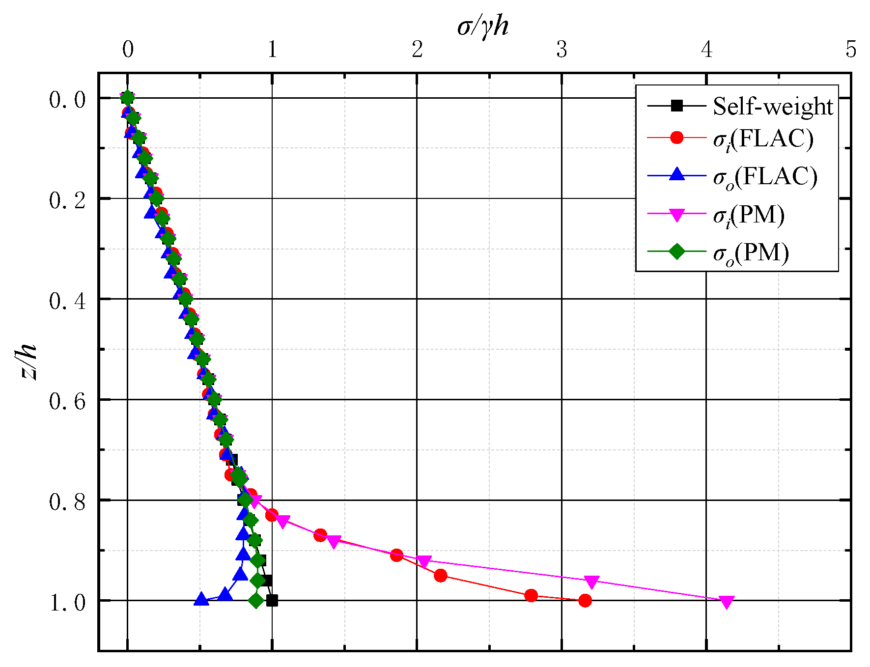
The vertical stress distributions in embankment.
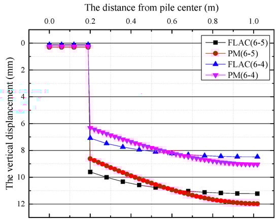
Figure 11.
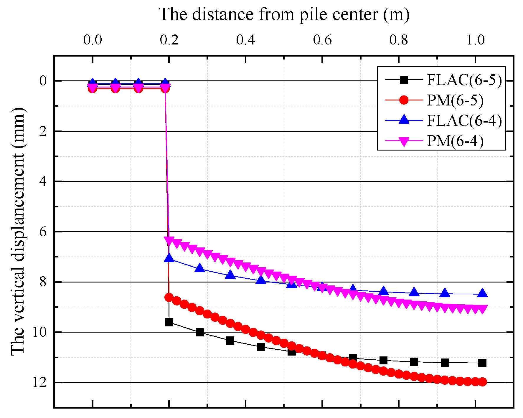
Settlement of the pile and the soft soil at the plane of the pile top.
The study focuses on the case of l = 6 and h = 5 due to the similarity in stress distribution between the two cases, as shown in Figure 10. Within the depth range of z/h < 0.756, the stress curves of the inner and outer hollow cylinders align closely with the self-weight stress curve. However, as z/h exceeds 0.756, the stress of the inner and outer hollow cylinders gradually deviates from the self-weight stress curve. This observation leads to the inference that the plane with z/h = 0.756 represents the equal settlement plane.
Table 4 presents a comparison between the proposed method and the numerical method for these two cases. For the case of l = 6 and h = 4, the heights of the equal settlement plane calculated by the proposed method and the numerical method are 1.192 m and 1.36 m, respectively. The corresponding pile–soil stress ratios obtained from the numerical method and the proposed method are 5.525 and 5.602, respectively. Likewise, for the other case of l = 6 and h = 5, the heights of the equal settlement plane are 1.22 m and 1.4 m, respectively, while the pile–soil stress ratios are 5.947 and 6.024, respectively. The relative errors of the pile–soil stress ratios compared to the numerical results are 1.39% and 1.29% for these two cases, respectively.
Table 4.
The summary of calculated values by the proposed method and numerical method.
Based on these findings, it is evident that the author’s improved soil arch model effectively simulates the soil arch effect in the embankment, and the proposed method demonstrates good agreement with the numerical results.
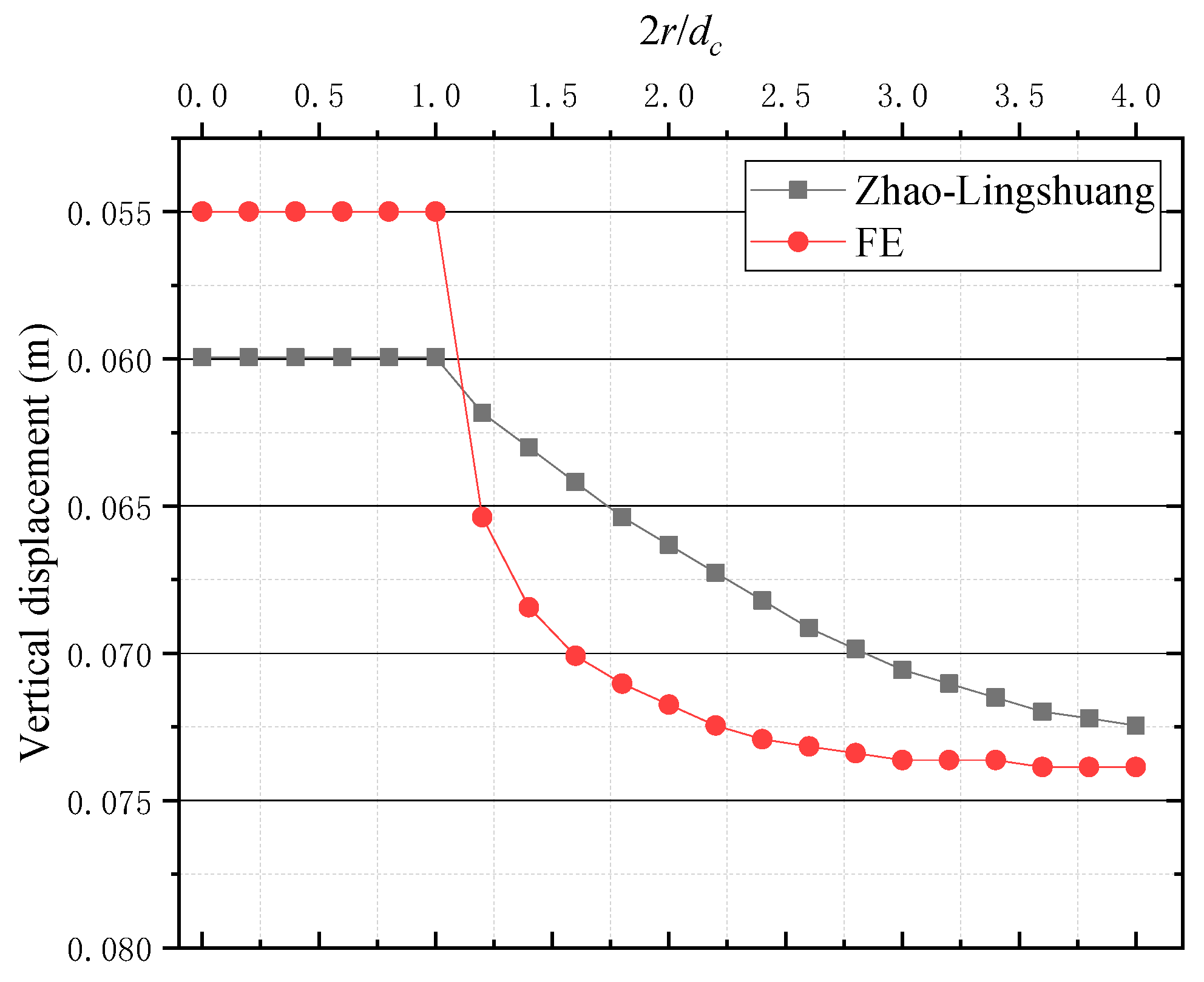
Figure 11 shows the settlement curves of the soft soil and pile top at the bottom of the embankment, observing distinct relative slips at the pile–soil interface. Figure 12 presents the results of scholar Zhao L.-S. [30], with the red curve clearly indicating significant relative slip at the pile–soil interface. However, the theoretical method of Zhao L.-S. assumes no relative displacement between the pile and soil at the interface, which contradicts the findings from the present investigation and other theoretical studies [29,30]. It is worth noting that many theoretical studies often overlook the significant relative slip at the pile–soil interface.

Figure 12.
Settlement of the pile and the soft soil at the plane of the pile top (Zhao, 2017 [30]).
In contrast, the proposed theory takes into account the relative slip between the pile and soil at the interface, which correlates well with the numerical simulations. The agreement between the proposed method and the numerical simulations provides strong evidence for the reliability of the proposed approach.
6. Conclusions
This paper presents a novel theoretical calculation approach for analyzing end-bearing pile-supported embankments. Through introducing an enhanced ideal elastoplastic model to simulate the friction at the pile–soil interface and considering factors such as relative slippage at the pile–soil interface, non-uniform deformation of soft soil, and the influence of ambient soil deformation on soil arching, the proposed method provides a more comprehensive understanding of the load transfer mechanism in pile-supported embankments, reflecting real-world engineering conditions more accurately. Several key conclusions can be drawn from this study:
- According to experimental data and numerical results, relative slippage at the pile–soil contact surface is a significant phenomenon under the load of the embankment and should not be overlooked in theoretical calculations.
- The relative displacement between the pile and soil initially exhibits a linear relationship with depth and later follows a quadratic function as the depth increases.
- When determining the ultimate shear stress between the soil and structure, the improved ideal elastic-plastic model, assuming a constant ultimate shear displacement regardless of normal stress, proves to be more appropriate compared to the ideal elastic-plastic model assuming a constant shear stiffness regardless of normal stress, as supported by experimental findings.
However, the current study still has the following limitations: the calculation method is only applicable to the analysis of end-bearing pile-supported embankments where the soil layer at the pile tip is relatively hard.
Overall, the proposed method provides valuable insights and practical applications for the analysis of end-bearing pile-supported embankments, contributing to the advancement of geotechnical engineering practices.
Author Contributions
Conceptualization, C.Z.; Methodology, C.Z.; Software, Y.L.; Validation, Y.L. and S.Y.; Formal analysis, Y.T.; Investigation, Y.T.; Resources, S.Y.; Data curation, S.Y.; Writing—original draft, C.Z. and G.W.; Supervision, C.H.; Project administration, G.W.; Funding acquisition, C.H., Y.L. and G.W. All authors have read and agreed to the published version of the manuscript.
Funding
The authors acknowledge the financial support of the National Natural Science Foundation of China (No. 52208352), the Open Fund of the National Engineering Research Center of Highway Maintenance Technology (No. KFJ230210), and the Shuimu Tsinghua Scholar Program of Tsinghua University (No. 2021SM007).
Data Availability Statement
All data, models, or codes that support the findings of this study are available from the corresponding author upon reasonable request.
Conflicts of Interest
Author Yufei Liu was employed by Hunan Chajiang Expressway Construction and Development Co., Ltd. The remaining authors declare that the research was conducted in the absence of any commercial or financial relationships that could be construed as a potential conflict of interest.
References
- Abusharar, S.W.; Zheng, J.-J.; Chen, B.-G.; Yin, J.-H. A simplified method for analysis of a piled embankment reinforced with geosynthetics. Geotext. Geomembr. 2009, 27, 39–52. [Google Scholar] [CrossRef]
- Ikbarieh, A.; Izadifar, M.; Abu-Farsakh, M.Y.; Voyiadjis, G.Z. A parametric study of embankment supported by geosynthetic reinforced load transfer platform and timber piles tip on sand. Transp. Geotech. 2023, 38, 100901. [Google Scholar] [CrossRef]
- Zhou, J.; Zhang, L.; Zhou, S.; Lin, W.; Chen, Y.H.; Zhao, M.H. Numerical multi-span segmented trapdoor test with viscoelastic boundary for soil arching within pile-supported embankment under cyclic loading. Int. J. Numer. Anal. Methods Geomech. 2023, 48, 28–54. [Google Scholar]
- Wu, G.; Zhao, M.; Zhang, C. Experimental Investigation on the Evolution of Soil Arching in Cohesive Soils Using a DIC Technique. Int. J. Geomech. 2024, 24, 04023270. [Google Scholar]
- Zhuang, Y.; Wang, K.Y.; Liu, H.L. A simplified model to analyze the reinforced piled embankments. Geotext. Geomembr. 2014, 42, 154–165. [Google Scholar] [CrossRef]
- Diao, Y.; Guo, Y.; Jia, Z.; Zheng, G.; Pan, W.; Shang, D.; Zhang, Y. A simplified method for investigating the bending behavior of piles supporting embankments on soft ground. Front. Struct. Civ. Eng. 2023, 17, 1021–1032. [Google Scholar]
- Ma, L.; Shen, S.; Luo, C.; Xu, Y. Field Evaluation on the Strength Increase of Marine Clay under Staged Construction of Embankment. Mar. Georesources Geotechnol. 2011, 29, 317–332. [Google Scholar]
- Zhang, C.; Zhao, M.; Zhao, H.; Zhou, S. Simplified Model of Column-Supported Embankment to Account for Nonuniform Deformations of Soils. J. Eng. Mech. 2020, 146, 04020060. [Google Scholar]
- Zhang, N.; Shen, S.L.; Wu, H.N.; Chai, J.C.; Xu, Y.S.; Yin, Z.Y. Evaluation of effect of basal geotextile reinforcement under embankment loading on soft marine deposits. Geotext. Geomembr. 2015, 43, 506–514. [Google Scholar] [CrossRef]
- Indraratna, B. Recent Advances in Vertical Drains and Vacuum Preloading for Soft Ground Stabilisation. In Proceedings of the 19th International Conference on Soil Mechanics and Geotechnical Engineering, Seoul, Republic of Korea, 17–21 September 2017; International Society for Soil Mechanics and Geotechnical Engineering: London, UK, 2017; pp. 141–166. [Google Scholar]
- Le, G.L.; Bergado, D.T.; Nguyen, T.N.T. Soft Ground Improved by Prefabricated Vertical Drains with Vacuum and Thermal Preloading. In Proceedings of the 20th International Conference on Soil Mechanics and Geotechnical Engineering (ICSMGE), Paris, France, 19–20 February 2018. [Google Scholar]
- Georgiannou, N.V.; Konstadinou, M.; Triantafyllos, P. Sand Behavior under Stress States Involving Principal Stress Rotation. J. Geotech. Geoenviron. Eng. 2018, 144, 04018028. [Google Scholar] [CrossRef]
- Wang, T.; Wang, P.; Yin, Z.-Y.; Zhang, F.; Xu, C. DEM-DFM Modeling Suffusion of Granular Soils under Triaxial Compression. Int. J. Geomech. 2025, 25, 2. [Google Scholar]
- Song, S.; Wang, P.; Yin, Z. Micromechanical modeling of hollow cylinder torsional shear test on sand using discrete element method. J. Rock Mech. Geotech. Eng. 2024, 16, 5193–5208. [Google Scholar] [CrossRef]
- Lai, H.J.; Zheng, J.J.; Zhang, R.J.; Cui, M.J. Classification and characteristics of soil arching structures in pile-supported embankments. Comput. Geotech. 2018, 98, 153–171. [Google Scholar] [CrossRef]
- Lu, W.; Miao, L. A simplified 2-D evaluation method of the arching effect for geosynthetic-reinforced and pile-supported embankments. Comput. Geotech. 2015, 65, 97–103. [Google Scholar] [CrossRef]
- Terzaghi, B.K. Theoretical Soil Mechanics; John Wiley & Sons, Inc.: New York, NY, USA, 1943. [Google Scholar]
- Guido, V.A.; Kneuppel, J.D.; Sweeney, M.A. Plate loading test on geogrid reinforced earth slabs. In Proceedings of the Geosynthetics ‘87, New Orleans, LA, USA, 24–25 February 1987; IFAI: Roseville, MN, USA, 1987; pp. 216–225. [Google Scholar]
- Collin, J.G. Column supported embankment design considerations. In Proceedings of the 52th Annual Geotechnical Engineering Conference, Falcon Heights, MN, USA, 27 February 2004; pp. 51–78. [Google Scholar]
- Hewlett, W.J.; Randolph, M.F. Analysis of piled embankments. Ground Eng. 1988, 21, 12–18. [Google Scholar]
- Kempfert, H.G.; Stadel, M.; Zaeske, D. Design of geosynthetic-reinforced bearing layers over piles. Bautechnik 1997, 74, 818–825. [Google Scholar]
- Van Eekelen, S.J.M.; Bezuijen, A.; van Tol, A.F. An analytical model for arching in piled embankments. Geotext. Geomembr. 2013, 39, 78–102. [Google Scholar] [CrossRef]
- Chen, R.P.; Chen, Y.M.; Han, J.; Xu, Z.Z. A theoretical solution for pile-supported embankments on soft soils under one-dimensional compression. Can. Geotech. J. 2008, 45, 611–623. [Google Scholar] [CrossRef]
- Stewart, M.E.; Filz, G.M. Influence of clay compressibility on geosynthetic loads in bridging layers for column-supported embankments. In Proceedings of the GeoFrontiers 2005, Austin, TX, USA, 24–26 January 2005; pp. 1–14. [Google Scholar]
- Naughton, P.J.; Kempton, G.T. Comparison of analytical and numerical analysis design methods for piled embankments. In Proceedings of the GeoFrontiers 2005, Austin, TX, USA, 24–26 January 2005; pp. 1–10. [Google Scholar]
- Ellis, E.; Aslam, R. Arching in piled embankments: Comparison of centrifuge tests and predictive methods—Part 2 of 2. Ground Eng. 2009, 42, 28–31. [Google Scholar]
- Han, J.; Wang, F.; Al-Naddaf, M.; Xu, C. Progressive Development of Two-Dimensional Soil Arching with Displacement. Int. J. Geomech. 2017, 17, 04017112. [Google Scholar] [CrossRef]
- Rui, R.; Han, J.; van Eekelen SJ, M.; Wan, Y. Experimental Investigation of Soil-Arching Development in Unreinforced and Geosynthetic-Reinforced Pile-Supported Embankments. J. Geotech. Geoenviron. Eng. 2019, 145, 04018103. [Google Scholar] [CrossRef]
- Alamgir, M.; Miura, N.; Poorooshasbh, H.B.; Madhav, M.R. Deformation analysis of soft ground reinforced by columnar inclusions. Comput. Geotech. 1996, 18, 267–290. [Google Scholar]
- Zhao, L.-S.; Zhou, W.-H.; Yuen, K.-V. A simplified axisymmetric model for column supported embankment systems. Comput. Geotech. 2017, 92, 96–107. [Google Scholar] [CrossRef]
- Low, B.K.; Tang, S.K.; Choa, V. Arching in Piled Embankments. J. Geotech. Eng. 1992, 120, 1917–1938. [Google Scholar]
- Deb, K. A mathematical model to study the soil arching effect in stone column-supported embankment resting on soft foundation soil. Appl. Math. Model. 2010, 34, 3871–3883. [Google Scholar]
- BS 8006:2010; British Standard Code of Practice for Strengthened, Reinforced Soils and Other Fills. British Standards Institution: London, UK, 2010.
- GGS (German Geotechnical Society). Recommendation for Design and Analysis of Earth Structures Using Geosynthetic Reinforcements, EBGEO; Wiley: Hoboken, NJ, USA, 2010. [Google Scholar]
- Indraratna, B.; Basack, S.; Rujikiatkamjorn, C. Numerical solution of stone column–improved soft soil considering arching. J. Geotech. Geoenviron. Eng. 2013, 139, 377–394. [Google Scholar] [CrossRef]
- Zhang, L.; Zhao, M.; Hu, Y.; Zhao, H.; Chen, B. Semi-analytical solutions for geosynthetic-reinforced and pile-supported embankment. Comput. Geotech. 2012, 44, 167–175. [Google Scholar] [CrossRef]
- Deb, K.; Mohapatra, S.R. Analysis of stone column-supported geosynthetic-reinforced embankments. Appl. Math. Model. 2013, 37, 2943–2960. [Google Scholar] [CrossRef]
- Shi, P. Pile Foundation Engineering Manual; China Communications Press: Beijing, China, 2008; pp. 178–194. [Google Scholar]
- Kezdi, A. Bearing capacity of piles and pile groups. In Proceedings of the IV ICSMFE, London, UK, 12–24 August 1957; pp. 46–51. [Google Scholar]
- Richard, R.M.; Abbott, B.J. Versatile Elastic-Plastic Stress-Strain Formula. J. Eng. Mech. Div. 1975, 101, 511–515. [Google Scholar]
- Kraft, L.M.; Richard, P.R.; Takaaki, K. Theoretical t-z Curves. J. Geotech. Eng. Div. 1981, 107, 1543–1561. [Google Scholar]
- Heydinger, A.G. Recommendations: Load-Transfer Criteria for Piles in Clay; Dept of Civil Engineering, University of Toledo: Toledo, OH, USA, 1987. [Google Scholar]
- Coombs, W.M.; Crouch, R.S.; Heaney, C.E. Observations on Mohr-Coulomb plasticity under plane strain. J. Eng. Mech. 2013, 139, 1218–1228. [Google Scholar] [CrossRef]
- Xu, X.; Dai, Z. Numerical implementation of a modified Mohr–Coulomb model and its application in slope stability analysis. J. Mod. Transp. 2017, 25, 40–51. [Google Scholar]
- Zvi, G.; Gellert, M.; Eitan, R. Analysis of arching pressures in ideal elastic soil. J. Soil Mech. Found. Div. 1970, 96, 1357–1372. [Google Scholar]
- Wu, G.; Zhao, M.; Zhao, H.; Xiao, Y. Effect of eccentric load on the undrained bearing capacity of strip footings above voids. Int. J. Geomech. 2020, 20, 04020078. [Google Scholar] [CrossRef]
- Wu, G.; Zhao, H.; Zhao, M.; Zhu, Z. Stochastic analysis of dual tunnels in spatially random soil. Comput. Geotech. 2021, 129, 103861. [Google Scholar] [CrossRef]
- Wu, G.; Zhang, R.; Zhao, M.; Zhou, S. Undrained stability analysis of eccentrically loaded strip footing lying on layered slope by finite element limit analysis. Comput. Geotech. 2020, 123, 103600. [Google Scholar] [CrossRef]
- Zeng, Y.; Wu, G. Seismic Stability of Dual Tunnels in Cohesive–Frictional Soil Subjected to Surcharge Loading. Appl. Sci. 2022, 12, 2779. [Google Scholar] [CrossRef]
- Randolph, M.F.; Wroth, C.P. Analysis of deformation of vertically loaded piles. J. Geotech. Eng. Div. 1978, 104, 1465–1488. [Google Scholar] [CrossRef]
- Reddy, E.S.; Chapman, D.N.; Sastry, V.V.R.N. Direct Shear Interface Test for Shaft Capacity of Piles in Sand. Geotech. Test. J. 2000, 23, 199–205. [Google Scholar] [CrossRef]
- Gómez, J.E.; Filz, G.M.; Ebeling, R.M.; Dove, J.E. Sand-to-Concrete Interface Response to Complex Load Paths in a Large Displacement Shear Box. Geotech. Test. J. 2008, 31, 358–369. [Google Scholar] [CrossRef]
- Borges, J.L.; Marques, D.O. Geosynthetic-reinforced and jet grout column-supported embankments on soft soils: Numerical analysis and parametric study. Comput. Geotech. 2011, 38, 883–896. [Google Scholar] [CrossRef]
- Wong, K.S.; Teh, C.I. Negative Skin Friction on Piles in Layered Soil Deposits. J. Geotech. Eng. 1995, 121, 457–465. [Google Scholar]
- Zhang, J.; Cui, X.; Huang, D.; Jin, Q.; Lou, J.; Tang, W. Numerical Simulation of Consolidation Settlement of Pervious Concrete Pile Composite Foundation under Road Embankment. Int. J. Geomech. 2016, 16, 1. [Google Scholar] [CrossRef]
- Wang, F.; Han, J.; Miao, L.-C.; Bhandari, A. Numerical Analysis of Embankments Supported by Geosynthetics over Drilled Shafts in Karst Terrains. Geosynth. Int. 2009, 16, 408–419. [Google Scholar] [CrossRef]
- Han, J.; Gabr, M.A. Numerical Analysis of Geosynthetic-Reinforced and Pile-Supported Earth Platforms over Soft Soil. J. Geotech. Geoenviron. Eng. 2002, 128, 44–53. [Google Scholar] [CrossRef]


Disclaimer/Publisher’s Note: The statements, opinions and data contained in all publications are solely those of the individual author(s) and contributor(s) and not of MDPI and/or the editor(s). MDPI and/or the editor(s) disclaim responsibility for any injury to people or property resulting from any ideas, methods, instructions or products referred to in the content. |
© 2025 by the authors. Licensee MDPI, Basel, Switzerland. This article is an open access article distributed under the terms and conditions of the Creative Commons Attribution (CC BY) license (https://creativecommons.org/licenses/by/4.0/).