Article

Thermal Evaluation of a Water-to-Air Heat Exchanger Combined with Different Roof Configurations for Passive Cooling

by
José-Manuel Almodóvar-Melendo
1,* and
Pablo La Roche
2
1
School of Architecture, University of Seville, Reina Mercedes 2, 41012 Sevilla, Spain
2
Department of Architecture, Cal Poly Pomona University, Pomona, CA 91768, USA
*
Author to whom correspondence should be addressed.
Buildings 2025, 15(7), 1098; https://doi.org/10.3390/buildings15071098
Submission received: 10 February 2025 / Revised: 23 March 2025 / Accepted: 24 March 2025 / Published: 27 March 2025
(This article belongs to the Special Issue Climate-Responsive Architectural and Urban Design)

Abstract

:
Traditional conservation strategies often prioritize minimizing water use; nevertheless, water can also enhance thermal comfort by incorporating a water-to-air heat exchanger (WAHE) alongside non-direct evaporative and radiant cooling techniques. A WAHE can be installed in features such as ponds, water tanks, or rainwater cisterns. This article assesses the cooling potential of two prototypes of roof ponds and a green roof connected to a WAHE, and the results are compared to a baseline unit featuring a roof that meets California’s energy code standards. Several testing units, measuring 1.35 × 1.35 × 1.35 m, with identical heat characteristics, excluding the roof, were constructed and tested. In the first system, the heat that the green roof could not absorb was transferred to a water reservoir and then dissipated to the outside. The first roof pond prototype features a 0.35 m deep water pond topped with a 0.03 m thick insulating panel and a spray system. The second roof pond variant has an aluminum sheet with a 0.10 m air gap above a 0.25 m deep water pond. The results suggest that combining a WAHE with different roof configurations offers promising benefits while keeping water consumption limited. Notably, when the WAHE is operating, the green roof increase its performance by 47%, the insulated roof pond by 22%, and the roof pond with an aluminum sheet by 13%.

1. Introduction

The construction industry contributes about 35% of global carbon emissions [1]. Accordingly, significant efforts and resources have been expended to achieve low-energy consumption buildings [2]. Roofs play a critical role in this issue as they can contribute substantially to heat gains during hot periods because of direct solar radiation. Studies indicate that in hot climates, roofs alone account for around 50% of the thermal loads in one-story buildings [3]. Nevertheless, roofs have significant potential to dissipate heat through mechanisms like conduction, longwave radiation, and evaporative cooling [4].
Traditional methods for reducing solar heat gain through roofs typically involve increasing thermal insulation and heat storage capacity. However, green roofs offer an alternative solution as they reduce the incidence of solar radiation by shading the roof’s surface, which is especially useful in hot climates [5,6,7]. Factors such as plant species, evaporative cooling rate, and the evapotranspiration ratio have also been identified as key contributors to the cooling effectiveness of indoor thermal environments [8,9,10,11]. Todeschini et al. created a dataset to identify archetypal green roof plants based on the local climate conditions [12].
Research on green roofs has demonstrated that green roofs can lower cooling energy demand by 2–48% [13,14,15]. Moreover, green roofs not only contribute to the reduction in energy consumption in buildings but also to other benefits, both climatic and non-climatic, that have generated interest in urban sustainability and decarbonization strategies [16]. In this regard, Tan et al. examined the current factors and strategies for reducing carbon dioxide through green roofs [17].
Furthermore, green roofs play a significant role in enhancing urban resilience by helping regulate temperatures in urban micro-climates and mitigating the urban heat island effect (UHI) [18]. Many studies have explored the impact of green roofs on local microclimate regulation across various climates and urban morphologies [5,19]. Santamouris has examined technologies designed to enhance the albedo of cities and has highlighted that green roofs have significant potential for reducing UHI [20]. Jamei et al. conducted a review of existing studies on the effect of green roofs on UHI mitigation in different climates, showing that the highest cooling benefits are observed in dry climates [21]. Other studies have focused on creating models to simulate the thermal performance of green roofs and UHI at the urban scale [22,23]. In addition, Sommese et al. have studied the environmental benefits of implementing green roofs in the renovation of existing areas [24].
Green roofs also contribute to alleviating urban flooding by capturing and storing rainwater. Cascone et al. examined the performance of three different green roof technologies, focusing on their effects on thermal regulation and water retention [25]. In addition, green roofs enhance the quality of the urban ecosystem and, as urban green spaces, help to reduce air and noise pollution. These benefits have a positive impact on the well-being of urban residents [11].
On the other hand, roof ponds also offer several advantages for cooling purposes because the water’s high thermal inertia helps to reduce peak temperatures. The concept of the roof pond was likely first explored by Jeffrey Cook [26]. In the 1970s, the “skytherm” system, which utilizes nocturnal radiation for cooling, was introduced [27]. Later, in 1994, Givoni [28] assessed the performance of roof ponds with fixed shading and insulation. Additionally, groundbreaking thermally active construction systems that leverage rainwater cisterns have been implemented [29]. Research on roof ponds has significantly increased in recent years. In 2008, a mechanically ventilated roof pond was evaluated, reporting promising outcomes in terms of passive cooling [30]. Moreover, other researchers have reviewed the advancements and variations in roof pond technologies [31,32].
Recent studies have explored hybrid passive cooling systems that combine conventional passive methods with other passive strategies, aiming to assess their cooling performance and suitability under various conditions. Among these, earth-to-air heat exchangers (EAHE) have been widely investigated as systems that utilize the ground’s thermal properties for heat storage and dissipation in conjunction with other passive techniques [33,34]. Due to the soil’s high thermal mass, temperature fluctuations below the surface are much smaller compared to those at ground level; as a result, temperatures tend to be higher than the outside air in winter and lower in summer. This property is utilized in EAHE systems to decrease the energy demand for both cooling and heating.
Other works have been published recently that review and discuss the existing literature on the design strategies and operating conditions of EAHEs [35]. A variety of models have been created to assess the energy efficiency of EAHE systems and examine the factors that affect their performance, such as the length of the EAHE in relation to the coefficient of performance (COP) [36]. In this regard, Alidrissi et al. have created a dataset for modeling and evaluating the performance of EAHE via on-site measurements [37]. Benkert et al. created a mathematical model validated through experiments [38]. Moreover, the EAHE system efficiency was also assessed, taking into account the influence of key boundary conditions [39].
Other studies have focused on examining the effectiveness of EAHE in various climatic conditions [40,41], as well as its application in different building types, such as residential, industrial, cultural, or educational [42].
Furthermore, research on enhancing the energy efficiency of EAHE through the use of hybrid systems is ongoing [43]. Huang et al. developed an innovative vertical EAHE system that incorporates baffles to divide the vertical duct into two ventilation channels, improving air circulation [44]. A thermal model has also been created to assess the indoor thermal conditions of a greenhouse with a semi-transparent PV roof integrated with an EAHE system [45]. Ren et al. proposed a multi-tubular PCM-filled EAHE using a finite difference method and validated the results with experimental data [46].
While EAHE systems are gaining popularity, there has been comparatively less research into WAHE systems. However, WAHEs have some advantages over EAHEs because water dissipates heat more effectively than earth due to its higher thermal capacity and conductivity [47,48]. The WAHE system was patented by Richard Bourne and David Springer in 1992.
This review of existing studies suggests that ad hoc strategies should be developed to optimize the cooling potential of green roofs and roof ponds. Specifically, research on smart green roofs highlights the need to design green roofs with enhanced capacity to dissipate thermal loads during the summer period [49]. However, a comparative study of hybrid systems that combine different roof variants to a WAHE has not been thoroughly conducted. This study aims to experimentally evaluate the passive cooling potential of a green roof and two roof pond variants conductively coupled with the indoor space. To achieve this, testing units with identical thermal envelopes, differing only in their roof designs, were constructed and evaluated in Southern California. This study also assessed the impact of a WAHE on the cooling efficiency of all roof configurations. The results were compared to a baseline unit featuring an insulated roof that meets the energy code standards of California.

2. Configuration of the Test Systems

To assess the advantages of using different roof prototypes along with a WAHE system, testing units were constructed at the Lyle Center for Regenerative Studies at Cal Poly Pomona University, which is situated near Los Angeles (California), in a climate characterized by hot dry summers and moderate winters. Analysis of the climatic parameters and design recommendations from the nearby Chino airport weather station are presented in the following chart (Figure 1).
The dimensions of all the testing units were 1.35 × 1.35 × 1.35 m, and they were oriented south, with a slight 10-degree rotation toward the west. All testing units were constructed using identical dimensions and materials for the walls, windows, and floor. However, the roofs differed based on the different configurations (Table 1). The thermal transmittance of the floor was 0.299 W/m2K, while the wall’s thermal transmittance was 0.308 W/m2K. To minimize heat gain, the walls were painted white. A 610 mm by 610 mm (2′ by 2′) double-glazed window was placed on the wall facing south. The window was evaluated with shading. For night ventilation, a 4-inch air extractor and an intake vent were placed on opposite walls. Furthermore, 89 mm wheels were installed beneath the test units to allow for adjustments to orientation and location. We have built and compared two roof pond variants and a green roof connected to a WAHE with a baseline unit that has an insulated roof that meets California’s energy code standards (Figure 2).
Data loggers were used to record thermal parameters, such as dry bulb temperature and mean radiant temperature, as well as relative humidity in 5-minute intervals. We have used HOBO-type devices (U12-012, UX 120-006 M, TMC6-HD) with a measurement spectrum of 0 to +100 °C and precision of ±0.5 °C. Calibration was performed prior to measurements to ensure the proper functionality of the system. These sensors were installed in accordance with DIN EN 60751 at multiple positions inside and outside the testing units to monitor the thermal environment and gather data from the series of tests conducted. Wire-type sensors with metal tips were used to measure the mean radiant temperature and outdoor temperature, which were connected to HOBO data loggers. The sensor measuring outdoor dry-bulb temperature was placed inside a sunshield made by onset computers and designed to block solar radiation, with the tip of the wire sensor located in the center of the sunshield. The sunshield had multiple vents to provide maximum airflow. The ventilation of the testing units was controlled by timers that regulated the operation of fans either simultaneously or independently, depending on the requirements. Figure 3 and Figure 4 display the sensor locations in the testing units.
The table below shows the layers and thermal characteristics of the testing unit along with all roof configurations, including the baseline unit (Table 1).

2.1. Configuration of the Green Roof

We have tested a green roof due to its growing popularity and superior cooling potential compared to traditional roofs [50]. Succulents with a leaf area index (LAI) of 4 were planted on the green roof. The roof measured 1.35 × 1.35 m and had a soil depth of 130 mm placed over 20 mm of gravel, a waterproof membrane, and a metal plate reinforced by 2” × 4” joists. The roof was gently sloped to ensure proper drainage, and a drainage conduit was installed at the end of the metal plate to capture and recycle excess irrigation water (Figure 5).

2.2. Configuration of the Roof Pond with Insulation and Nighttime Spraying

A pond, 0.35 m in depth, was located on the roof. It was sheltered by a 3 cm thick floating polystyrene insulation layer. Previous studies have shown that increasing thickness beyond this value does not significantly enhance performance [51]. A spray system is positioned above the pond to flow water across the insulation at night, cooling the water through radiation and evaporation [50]. The external face of the insulation is painted white to reflect direct solar radiation during the day while promoting long-wave radiation at night. The spraying system is located 0.5 m over the insulation layer, which is the lowest height needed for effective evaporative cooling [52]. The roof’s supporting structure consists of a metal plate that provides efficient heat transfer to the interior space. This thermal-insulated roof pond system was designed by Givoni and experimentally assessed with La Roche [53].
During the day, the insulation layer helps reduce water overheating. At night, however, the water cools naturally via evaporation and long-wave radiation towards the sky. Previous studies have indicated that this system provides a stronger cooling effect than an uncovered pond with spraying and performs nearly the same as a shaded and ventilated pond [54]. Moreover, when the external wet bulb temperature exceeds the water temperature, the spray system can heat the water. Therefore, the spray operates only at night (between 7:00 p.m. and 7:00 a.m.) to enhance the system’s efficiency and minimize water loss through evaporation (Figure 6). It is worth noting that fossil fuel plants require a significant amount of water to operate. The consumption of raw water in various plant components, such as the cooling tower or condenser, ranges from 300 to 600 gallons per MWh, or 1.15 to 2.3 L per kWh. As a result, the overall water usage of the system described above is negligible.

2.3. Configuration of the Roof Pond Sealed by an Aluminum Sheet

This prototype is an evaporeflective roof featuring a 25 cm deep water pond, covered by a flat aluminum sheet separated from the water by a 10 cm air gap. The roof pond is securely sealed to avoid water loss through evaporation. The exterior surface of the aluminum sheet is coated in white paint to improve its reflective capabilities (Figure 7). During the nighttime, the aluminum sheet’s temperature drops beneath water temperature, causing condensation of water vapor. Heat is thus dissipated to the outside. An adaptive numerical model for a similar aluminum-covered pond roof was previously designed by Ben Cheikh and Bouchair [55]. This model was later discussed and compared with other pond roof variants [31]. The pond roof is upheld by a metal plate that ensures effective heat transfer to the indoor air of the testing unit.

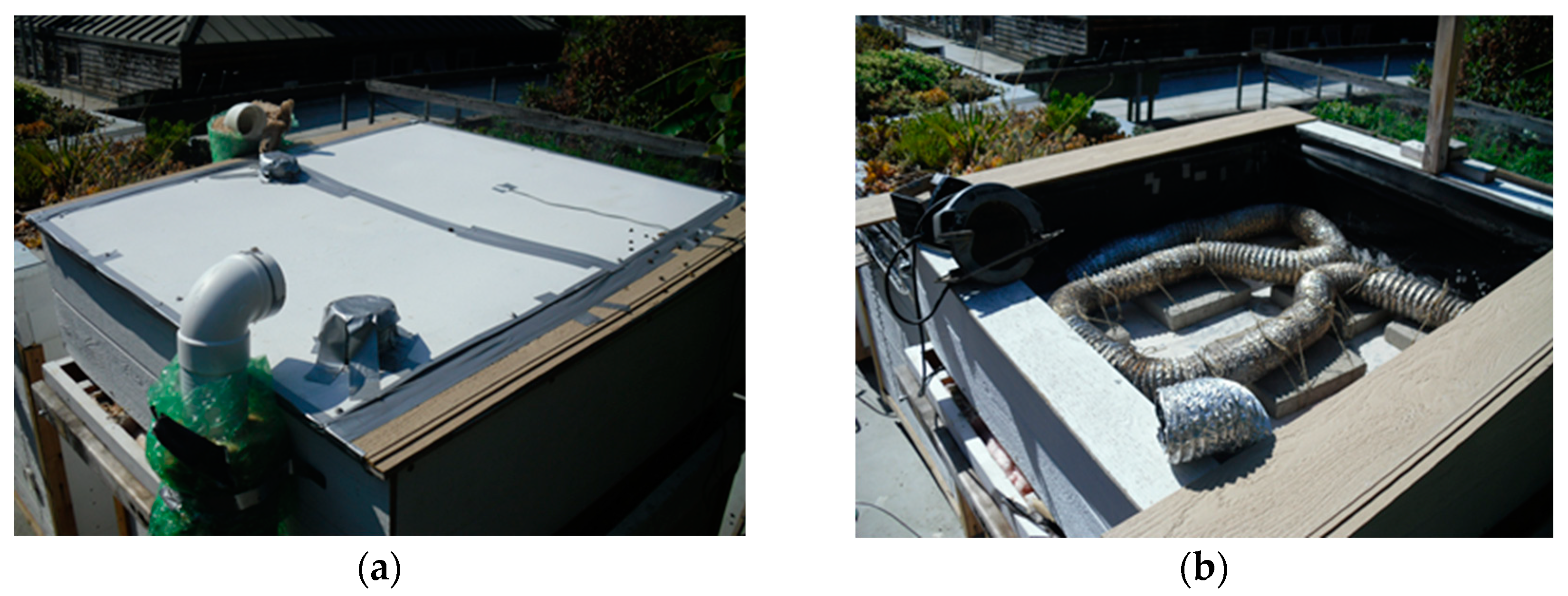
2.4. Configuration of the WAHE

A pipe links the interior of the testing units to all roof ponds and a water pond that matches the floor dimensions of the testing units (1.35 × 1.35 m) and is 0.35 m deep in the case of the green roof. The pond’s water is utilized to lower the temperature inside the testing units via a WAHE. A ventilator circulates air from the testing units to the ponds through a WAHE placed within the pond’s water. The air conveys heat to the submerged pipeline through convection, which subsequently transfers the heat to the water by conduction but in the liquid. Finally, the pre-cooled air is reintroduced into the testing unit to decrease the indoor temperature.
A PVC conduit encased in batt insulation, waterproof liner, and aluminum foil channels air from the interior of the testing units to the pond. Conversely, a flexible uninsulated aluminum pipe placed underwater enhances the pipe’s thermal conductivity to enhance the WAHE system efficiency. The underwater aluminum pipe has a diameter of 10.16 cm (4 inches) and a length of 3.5 m (Figure 5, Figure 6 and Figure 7). The fan operates continuously, both day and night, with a flow speed of 1.5 m/s to consistently lower the interior temperature.

3. Analysis of Findings

The authors have selected various test series conducted between June and August 2022 in order to compare the performances of all roof variants with a baseline unit that meets California’s energy regulations. To assess the impact of the WAHE on all roof configurations, we have conducted multiple series with the WAHE system both active and inactive. The parameters used to assess the system’s efficiency include the cooling performance of the pond water and the influence of all roof designs on cooling the space beneath through conductive energy transfer. Additionally, the heat transfer efficiency of the WAHE and its effect on improving the cooling performance of all roof variants have been evaluated.

3.1. Green Roof

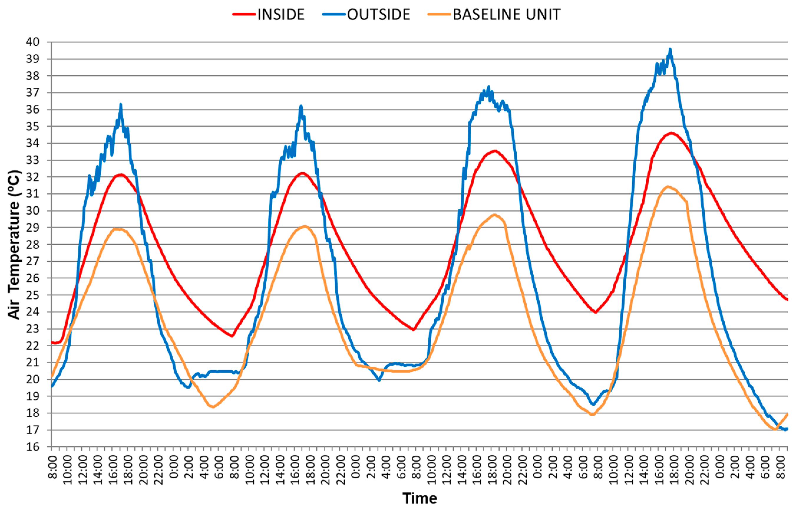
3.1.1. Green Roof When the WAHE Is Inactive

This series, which began on 12 June, assesses the cooling impact of the green roof. Maximum temperatures serve as a reliable measure of the system’s cooling efficiency. Better performance is achieved when the difference between the maximum indoor and outdoor temperatures is higher, with the indoor temperature being lower. The findings indicate that when outdoor temperatures peak at approximately 35 °C, the testing unit’s interior temperature is about 3 °C cooler, whereas the baseline unit’s maximum temperature is approximately 5 °C lower than the outside temperature (Figure 8).

3.1.2. Green Roof When the WAHE Is Active

This series, starting on 19 June, analyzes the green roof’s cooling performance when the WAHE system is operating. The findings indicate that the WAHE significantly enhances the green roof’s cooling potential. When outdoor dry temperatures exceed 35 °C, the inside temperature is lowered by 9–10 °C, which is 6 °C more than when the WAHE system is not in operation.
The pond water temperature cools rapidly at night to align closely with the ambient temperature, typically dropping under 20 °C. In the daytime, the water temperature warms by only about 2 °C compared to its nighttime temperature, while the ambient temperature rises by approximately 15 °C. Therefore, the pond’s water has a significant cooling potential, remaining over 10 °C cooler than the outside temperature.
At night, the testing unit temperature closely matches the water temperature, helping to reduce the maximum temperature in the daytime. The thermal difference between the water and the air precooled by the WAHE system was under 2 °C, confirming the efficient performance of the WAHE (Figure 9).

3.2. Roof Pond with Insulation and Nighttime Spraying

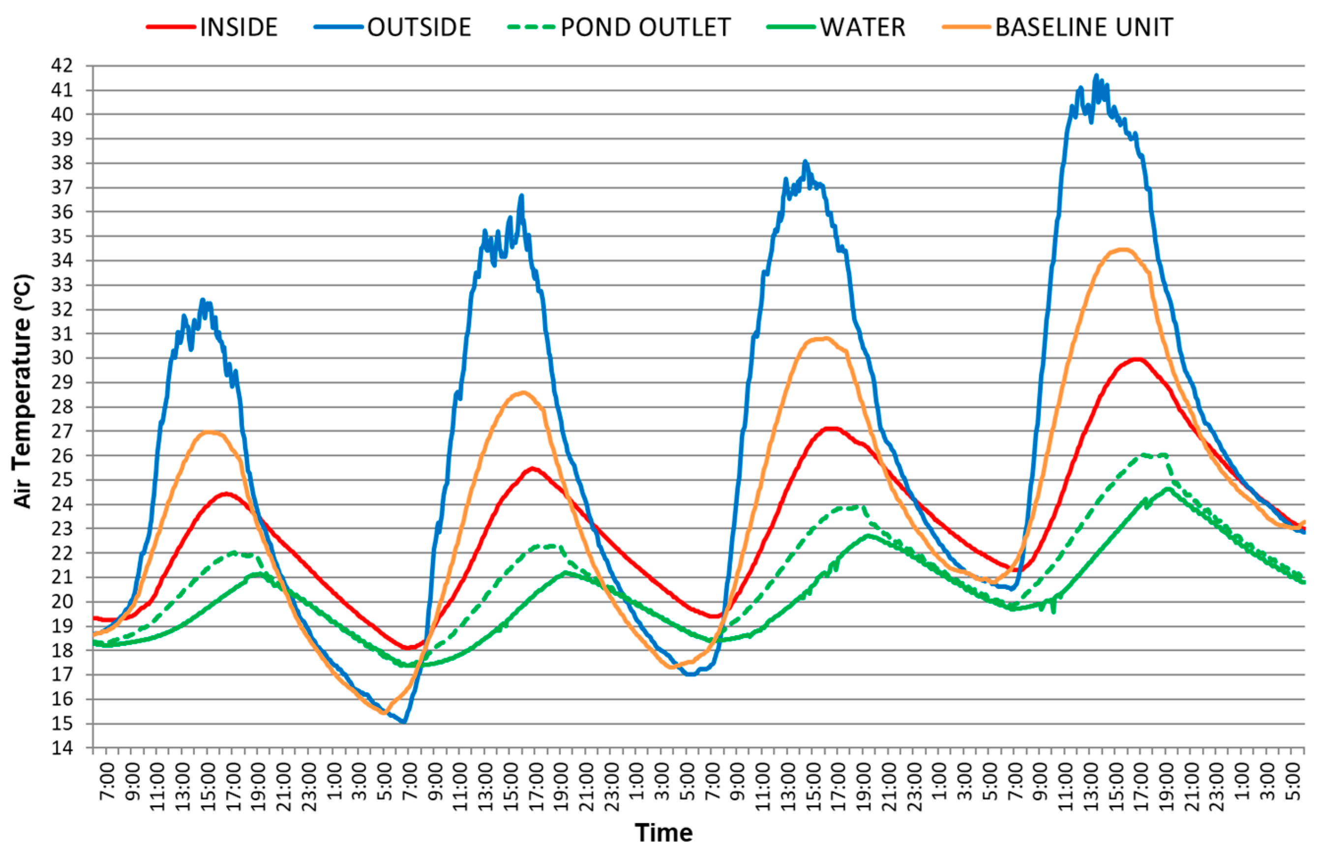
3.2.1. Roof Pond with Insulation and Nighttime Spraying When the WAHE Is Inactive

This series, initiated on 3 July, evaluates the cooling efficiency of a roof pond protected by floating insulation and nighttime spraying. The WAHE does not operate in this series. The findings demonstrate the effective cooling potential of this roof pond configuration (Figure 10). When the outdoor temperature exceeds 35 °C, the inside temperature of the testing unit remains below 27 °C, around 8 °C less. In contrast, the maximum temperature in the baseline unit is approximately 29 °C, 2 °C above the testing unit. Therefore, the testing unit provides superior cooling performance compared to the baseline unit that complies with California’s energy regulations.

3.2.2. Roof Pond with Insulation and Nighttime Spraying When the WAHE Is Active

This series, starting on 17 July, assesses the same roof setup as in the previous series but with the WAHE operating continuously, day and night. The findings show a significant improvement in system performance. When the ambient temperature is approximately 35 °C, the maximum interior temperature remains under 25 °C, approximately 3 °C lower than when the WAHE is inactive. The maximum thermal difference between the pond water and the precooled air at the WAHE outlet is just about 1 °C, indicating highly efficient heat transfer between the air flowing through the WAHE and the water.
The evaporation rate is 3.5 mm per day (approximately 6.3 L). Additionally, the data reveal that the air temperatures at the testing unit outlet and pond inlet, as well as those at the pond outlet and testing unit inlet, are nearly identical. Thus, there is a negligible heat loss during air circulation through the pipes connecting the testing unit interior and the pond water (Figure 11). The evaporation rate is 3.5 mm per day, roughly corresponding to a daily water consumption of just 6.3 L. Additionally, the data reveal that air temperatures at both the testing unit outlet and water pond inlet, as well as those at the water pond outlet and testing unit inlet, are almost identical. Thus, there is negligible heat loss in the pipes linking the interior of the test units and the ponds (Figure 11).

3.3. Roof Pond Sealed by an Aluminum Sheet

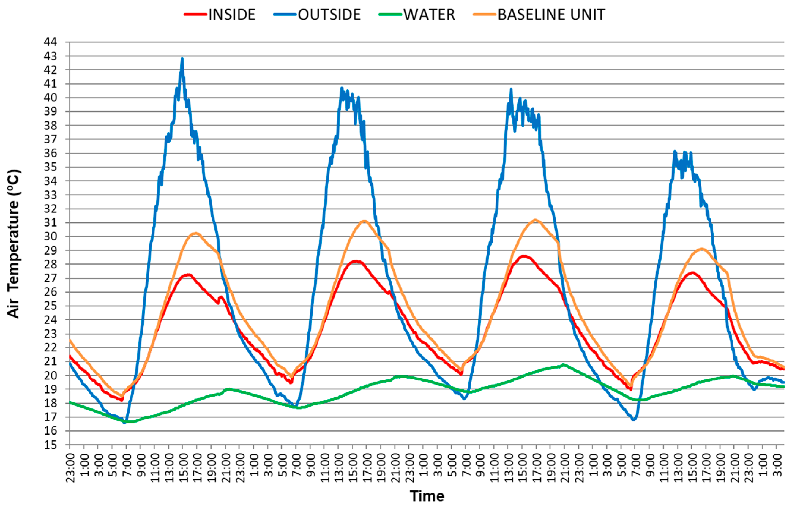
3.3.1. Roof Pond Sealed by an Aluminum Sheet When the WAHE Is Inactive

This series, conducted on 2 August, assesses the cooling potential of the roof pond sealed by an aluminum sheet when the WAHE is not working. The results indicate that the maximum temperature reached by the water is only somewhat higher than in the case of a roof pond protected by floating insulation and nighttime spraying when the WAVE is not in operation. Nevertheless, the thermal difference between indoor and outdoor remains significant, i.e., around 7 °C when the outdoor temperature is above 35 °C. The baseline unit performance is slightly lower than the testing unit, reaching a maximum indoor temperature 1 °C higher than the testing unit (Figure 12).

3.3.2. Roof Pond Sealed by an Aluminum Sheet When the WAHE Is Active

This series, starting on 8 August, evaluates the same configuration as the previous one but with the WAHE in operation. The maximum indoor temperature of the testing unit is over 2 °C lower than the maximum indoor temperature of the baseline unit, and the maximum temperature difference between inside and outside exceeds 8 °C when ambient temperatures are above 35 °C. These findings confirm that the WAHE system significantly enhances the roof pond’s cooling performance (Figure 13).

4. Comparison of Test Outcomes

We have used the temperature difference ratio (TDR) concept developed by Baruch Givoni [56] to compare series registered at different times and weather conditions. The TDR shows the potential to reduce the maximum indoor temperature in relation to the outdoor temperature swing, allowing for comparisons between different series taken in different periods. The TDR value is obtained by dividing the maximum outdoor temperature reduction in the indoor space by the daily thermal swing, as shown below.
TDR = (Tmaxi_out–Tmaxi_ins)/(Tmaxi_out–Tmini_out)
where Tmaxi_out = higher outside temperature (°C); Tmaxi_ins = higher inside temperature (°C); and Tmini_out = lower outside temperature (°C).
The numerator signifies the thermal difference between the indoor and outdoor temperature, whereas the denominator represents the difference between the maximum and minimum outside temperature. A negative value signifies that the peak indoor temperature exceeds the outdoor temperature. A greater TDR suggests more efficient cooling, since the difference between the inside and outside temperatures is higher. Therefore, the closer the value is to 1, the better the performance. To make the results easier to understand, the TDR values are presented as a percentage, with 100% representing the optimal performance.
TDR shows the potential to reduce the maximum indoor temperature based on the outdoor temperature swing, allowing for comparisons between different series taken in different periods. We have used the TDR concept to compare measured data in different roof configurations, both with the WAHE system on and off, as well as the baseline unit (Figure 14, Figure 15, Figure 16 and Figure 17). As TDR is computed on a daily basis, in each of the points in Figure 14, Figure 15, Figure 16 and Figure 17, a trend line has been drawn for each series, represented by equations whereby y denotes the TDR (%) and x represents the outdoor temperature swing (°C). Additionally, the determination coefficient (R2) for each series is provided.
Figure 14 compares all roof configurations with the WAHE in operation and the baseline unit, while additional comparisons of performance are made with the WAHE on and off for the green roof (Figure 15), insulated roof (Figure 16), and roof pond with an aluminum sheet (Figure 17).
Figure 10 illustrates that all roof configurations with WAHE outperform the energy code compliant baseline unit. The insulated roof has the best performance, showing an improvement of 44% over the baseline unit. The following best performing roof configurations are the green roof and the aluminum roof, which are 38% and 31% better, respectively, when the daily outdoor temperature swing is 20 °C.
Additionally, the findings indicate that when the WAHE is in operation, all roof configurations significantly increase their performance. Notably, during the time in which the WAHE is inactive, the green roof decreases its efficiency by 47%, shifting from 18% worse than the baseline unit to 22% better (Figure 15). Similarly, the insulated roof’s performance decreases by 22% (Figure 16), and the roof pond with an aluminum sheet drops by 13% (Figure 17). In both roof pond variants, the performance exceeds the baseline unit, even if the WAHE is inactive, i.e., around 29% and 21%, respectively, when the daily thermal amplitude is 20 °C.

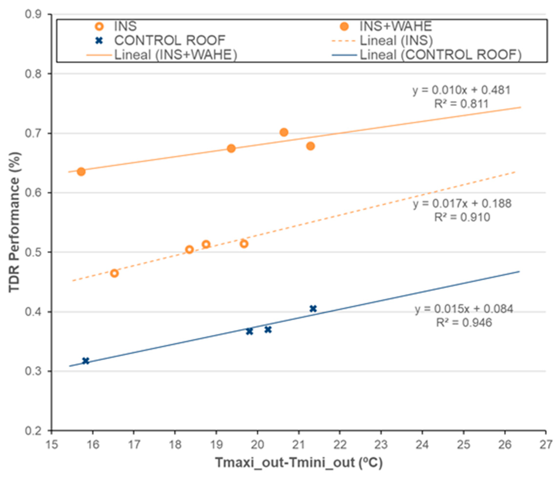
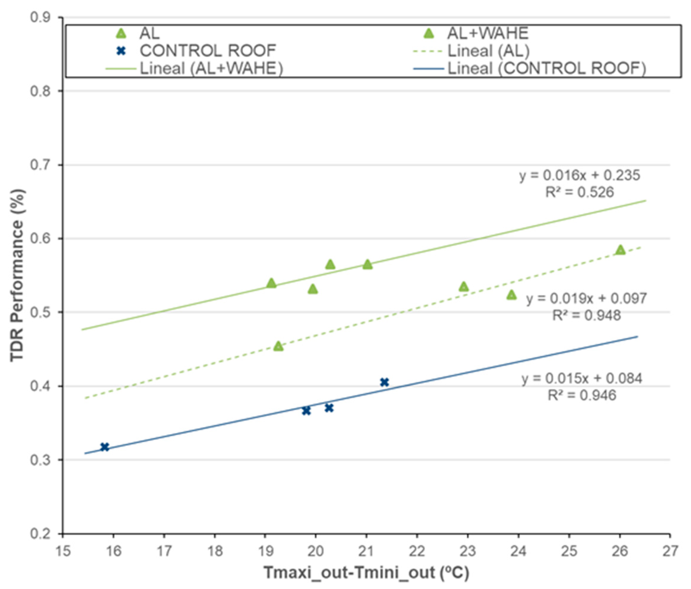
5. Temperature Difference Ratio (TDR) Estimation

TDR can be applied to obtain predictive equations from monitoring data. The equations below represent the TDR for each system configuration. They are obtained by replacing y with TDR (%) and x with the outdoor temperature swing in the equations from Figure 14, Figure 15, Figure 16 and Figure 17.
Green roof (GR):
TDR = 0.019 ∗ (Tmaxi_out–Tmini_out) − 0.094; R2 = 0.68.
Green roof + WAHE (GR + WAHE):
TDR = 0.013 ∗ (Tmaxi_out–Tmini_out) + 0.340; R2 = 0.55.
Roof pond with floating insulation (INS):
TDR = 0.017 ∗ (Tmaxi_out–Tmini_out) + 0.188; R2 = 0.91.
Roof pond covered with floating insulation + WAHE (INS + WAHE):
TDR = 0.010 ∗ (Tmaxi_out–Tmini_out) + 0.481; R2 = 0.81.
Roof pond sealed by an aluminum sheet (AL):
TDR = 0.019 ∗ (Tmaxi_out–Tmini_out) + 0.097; R2 = 0.94.
Roof pond sealed by an aluminum sheet + WAHE (AL + WAHE):
TDR = 0.016 ∗ (Tmaxi_out–Tmini_out) + 0.235; R2 = 0.52.
After calculating the TDR by applying Equations (2)–(7), the maximum indoor temperature in each case can be estimated by utilizing Equation (1) and solving the following:
Tmaxi_ins = Tmaxi_out − [TDR ∗ (Tmaxi_out − Tmini_out)]
where the daily thermal amplitude needs to be acknowledged. The equations stated above, based on the results of on-site measurements, enable the maximum indoor temperature to be determined as a function of the maximum outdoor temperature and the daily thermal amplitude. They can be applied in real scenarios for south-facing buildings with shaded windows, low-mass walls, and selected roof configurations to estimate the maximum inside temperature.

6. Conclusions

This study has experimentally assessed a green roof and two roof pond variants, along with the improvement of their cooling potential by incorporating an innovative water-to-air heat exchanger that moves air between the interior space of the testing units and a water pond.
The results obtained are promising and show that the thermal behavior appears to improve in all roof configurations when the WAHE system is operating. The best performance is achieved in the roof pond covered by a floating insulation roof with nighttime spraying combined with a WAHE. This configuration maintains indoor temperatures below 25 °C when ambient temperatures exceed 35 °C, representing a reduction of around 10 °C. This insulated roof pond outperforms the baseline unit by 44%, followed by the green roof and the roof pond sealed by an aluminum sheet, which show improvements of 38% and 31%, respectively, when the daily thermal amplitude is over 20 °C. In the case of the green roof, although the water pond is not connected to the interior space, it can offer substantial cooling, which is better than that of the roof pond sealed by an aluminum sheet.
Additionally, the results indicate that all roof configurations significantly improve efficiency when the WAHE is not operating. Notably, the green roof decreases its performance by 47%, shifting from 22% better than the baseline unit to 18% worse (Figure 15). Similarly, the insulated roof’s performance decreases by 22% (Figure 16), and the roof pond with an aluminum sheet drops by 13% (Figure 17). In both roof pond variants, the performance is better than the baseline unit, even if the WAHE is off, i.e., around 29% and 21%, respectively, whilst the daily temperature swing is over 20 °C.
A green roof with a water-based radiant evaporative cooling system has previously been assessed at the Lyle Center for Regenerative Studies [57]. The green roof featured pipes embedded in the soil connected to a radiator inside the test cell through which water circulated. The radiator absorbed heat from the interior of the cells and then dissipated it through the green roof using a sprinkler system that reduced the ground temperatures through evaporative radiant cooling. Different operation rules and schedules were tested. In the most optimized configuration, the interior temperature was reduced by 2 °C when the system was running. The results from the current study using a WAHE system demonstrate a significantly greater cooling potential compared to previous research. In more detail, the on-site measurements show that the green roof can lower the maximum indoor temperature by about 6–7 °C when the WAHE system is active.
Green roofs can also be designed in combination with roof ponds, allowing them to mutually benefit from the joint use of WAHE systems. This approach can significantly enhance their thermal performance while also creating attractive spaces. These hybrid designs should also be integrated into community spaces alongside other green technologies such as solar panels. Thus, new innovations and more effective approaches can be developed and implemented on a large scale through urban planning policies, encouraging integrated sustainability practices in buildings to move towards more resilient cities with enhanced environmental comfort.
The findings of this study demonstrate that the WAHE is an efficient passive substitute to traditional active cooling systems. It provides substantial cooling in buildings by utilizing water reservoirs as thermal sinks. The water reservoir employed in this research is comparatively small in relation to the dimension of the testing units. This suggests that the evaluated systems would perform especially well with a larger water body.
Additional series should be conducted to enhance the accuracy of the results. Similarly, further studies should be carried out to assess the performance improvements in other green roof and roof pond configurations, where the combined effect of thermal mass, variable insulation, and ventilation is optimized. On this basis, previous research at the Lyle Center for Regenerative Studies compared the thermal performance of an insulated green roof with other roof configurations to assess the combined impact of thermal mass and insulation [1]. Specifically, a non-insulated green roof and a green roof with a variable insulation system were studied. The variable insulation system consists of a plenum beneath the green roof, through which air inside the cell is recirculated on different schedules. This approach creates a system with adjustable insulation. The findings indicate that this system provides the benefits of an insulated green roof in winter and the absence of insulation in summer, optimizing its thermal performance in both cases.
Future research should include further experiments to assess the efficiency of a similar variable insulation system applied to different green roof and roof pond configurations in combination with a WAHE. Furthermore, the operating rules established by La Roche and Milne could be applied to control the ventilation of the variable insulation, while a fan sensor could be used to enable natural ventilation or recirculate indoor air through the WAHE according to seasonal requirements. Testing the system under more extreme conditions would help determine its operational limits. Moreover, developing numerical models and predictive equations is essential for adapting the system to different building types and climatic conditions.

Author Contributions

Conceptualization, J.-M.A.-M.; methodology, J.-M.A.-M. and P.L.R.; validation, J.-M.A.-M. and P.L.R.; formal analysis, J.-M.A.-M.; investigation, J.-M.A.-M. and P.L.R.; resources, P.L.R.; data curation, J.-M.A.-M. and P.L.R.; writing—original draft preparation, J.-M.A.-M.; writing—review and editing, J.-M.A.-M.; visualization, J.-M.A.-M.; supervision, J.-M.A.-M. and P.L.R.; project administration, J.-M.A.-M. and P.L.R.; funding acquisition, J.-M.A.-M. All authors have read and agreed to the published version of the manuscript.

Funding

This project was supported by a grant of the University of Seville (call 2023/2024) for exchange mobility at the University of California.

Data Availability Statement

Data are contained within the article or referenced material.

Acknowledgments

J.M. Almodóvar express his gratitude to Alan Locke for his generous assistance during his research at UCLA.

Conflicts of Interest

The authors declare no conflicts of interest.

References

  1. La Roche, P.; Berardi, U. Comfort and energy savings with active green roofs. Energy Build. 2014, 82, 492–504. [Google Scholar] [CrossRef]
  2. Ruiz-Valero, L.; Flores-Sasso, V.; Prieto-Vicioso, E.; Fernández-Flores, G. Assessment of Vernacular Housing in the Dominican Republic Using Simulations. Buildings 2024, 14, 3365. [Google Scholar] [CrossRef]
  3. Nahar, N.M.; Sharma, P.; Purohit, M.M. Studies on solar passive cooling techniques for arid areas. Energy Convers. Manag. 1999, 40, 89–95. [Google Scholar] [CrossRef]
  4. Wang, Y.; Wang, Z.; Rahmatollahi, N.; Hou, H. The impact of roof systems on cooling and building energy efficiency. Appl. Energy 2024, 376, 124339. [Google Scholar] [CrossRef]
  5. Joshi, M.Y.; Rodler, A.; Musy, M.; Guernouti, S.; Teller, J. Influence of urban morphology on potential of green roofs in regulating local microclimate: A case study of Liège, Belgium. Urban Clim. 2024, 58, 102144. [Google Scholar] [CrossRef]
  6. Ouldboukhitine, S.E.; Belarbi, R.; Jaffal, I.; Trabelsi, A. Assessment of green roof thermal behavior: A coupled heat and mass transfer model. Build. Environ. 2011, 46, 2624–2631. [Google Scholar] [CrossRef]
  7. Joshi, M.Y.; Teller, J. Assessing urban heat island mitigation potential of realistic roof greening across local climate zones: A highly-resolved weather research and forecasting model study. Sci. Total Environ. 2024, 944, 173728. [Google Scholar] [CrossRef]
  8. Xu, H.; Chen, H.; Qian, C.; Li, J. The Evapotranspiration Characteristics and Evaporative Cooling Effects of Different Vegetation Types on an Intensive Green Roof: Dynamic Performance Under Different Weather Conditions. Sustainability 2024, 16, 10812. [Google Scholar] [CrossRef]
  9. Olivieri, F.; Di Perna, C.; D’Orazio, M.; Olivieri, L.; Neila, J. Experimental measurements and numerical model for the summer performance assessment of extensive green roofs in a Mediterranean coastal climate. Energy Build. 2013, 63, 1–14. [Google Scholar] [CrossRef]
  10. Liu, K.K.Y.; Minor, J. Performance Evaluation of an Extensive Green Roof, Green. In Proceedings of the Rooftops Sustainable Communities Conference, Washington, DC, USA, 5–6 May 2015; pp. 1–11. [Google Scholar]
  11. Saqib, A.; Khan, M.S.U.; Rana, I.A. Bridging nature and urbanity through green roof resilience framework (GRF): A thematic review. Nat. Based Solut. 2024, 6, 100182. [Google Scholar] [CrossRef]
  12. Todeschini, C.C.; Fett-Neto, A.G. Life at the Top: Extensive Green Roof Plant Species and Their Traits for Urban Use. Plants 2025, 14, 735. [Google Scholar] [CrossRef]
  13. Dhahri, M.; Yüksel, A.; Aouinet, H.; Wang, D.; Arıcı, M.; Sammouda, H. Efficiency Assessment on Roof Geometry and Trombe Wall Shape for Improving Buildings’ Heating Performance. Buildings 2024, 14, 1297. [Google Scholar] [CrossRef]
  14. Wollschläger, N.; Schlink, U.; Trabitzsch, R.; Moeller, L. Weather dynamics affect the long-term thermal and hydrological performance of different green roof designs. Sci. Total Environ. 2024, 957, 177376. [Google Scholar] [CrossRef] [PubMed]
  15. Qin, X.; Wu, X.; Chiew, Y.M.; Li, Y. A green roof test bed for storm water management and reduction of urban heat island effect in Singapore. Br. J. Environ. Clim. Change 2012, 2, 410–420. [Google Scholar] [CrossRef]
  16. Jelena Aleksejeva, J.; Gerasimos Voulgaris, G.; Alexandros Gasparatos, A. Systematic review of the climatic and non-climatic benefits of green roofs in urban areas. Urban Clim. 2024, 58, 102133. [Google Scholar] [CrossRef]
  17. Tan, T.; Kong, F.; Yin, H.; Cook, L.M.; Middel, A.; Yang, S. Carbon dioxide reduction from green roofs: A comprehensive review of processes, factors, and quantitative methods. Renew. Sustain. Energy Rev. 2023, 182, 113412. [Google Scholar] [CrossRef]
  18. Iaria, J.; Susca, T. Analytic Hierarchy Processes (AHP) evaluation of green roof- and green wall- based UHI mitigation strategies via ENVI-met simulations. Urban Clim. 2022, 46, 101293. [Google Scholar] [CrossRef]
  19. Li, Q.; Taubenböck, H.; Zhu, X.X. Identification of the potential for roof greening using remote sensing and deep learning. Cities 2025, 159, 105782. [Google Scholar] [CrossRef]
  20. Santamouris, M. Cooling the cities—A review of reflective and green roof mitigation technologies to fight heat island and improve comfort in urban environments. Sol. Energy 2014, 103, 682–703. [Google Scholar] [CrossRef]
  21. Jamei, E.; Chau, H.W.; Seyedmahmoudian, M.; Stojcevski, A. Review on the cooling potential of green roofs in different climates. Sci. Total Environ. 2021, 791, 148407. [Google Scholar] [CrossRef]
  22. Palomo Del Barrio, E. Analysis of the green roofs cooling potential in buildings. Energy Build. 1998, 27, 179–193. [Google Scholar] [CrossRef]
  23. Li, D.; Bou-Zeid, E.; Oppenheimer, M. The effectiveness of cool and green roofs as urban heat island mitigation strategies. Environ. Res. Lett. 2014, 9, 055002. [Google Scholar] [CrossRef]
  24. Sommese, F.; Diana, L. A holistic framework for the implementation of green roofs on existing buildings: A case study in the Mediterranean climate of Naples. Build. Environ. 2025, 274, 112811. [Google Scholar] [CrossRef]
  25. Cascone, S.; Vitaliano, S. Innovative green roof technologies in Mediterranean climate: Implications for sustainable design of the built environment. Build. Environ. 2025, 273, 112715. [Google Scholar] [CrossRef]
  26. Cook, J. Passive Cooling; MIT Press: London, UK, 1985. [Google Scholar]
  27. Hay, H.R.; Yellot, J. Natural air conditioning with roof pools and movable insulation. ASHRAE Transact. 1978, 75, 165–172. [Google Scholar]
  28. Givoni, B. Passive and Low Energy Cooling; Van Nostrand Reinhold: London, UK, 1994. [Google Scholar]
  29. Kalz, D.E.; Wienold, J.; Fischer, M.; Cali, D. Novel heating and cooling concept employing rainwater cisterns and thermos-active building systems for a residential building. Appl. Energy 2010, 87, 650–660. [Google Scholar] [CrossRef]
  30. Kharrufa, S.N.; Adil, Y. Roof pond cooling of buildings in hot arid climates. Build. Environ. 2008, 43, 82–89. [Google Scholar] [CrossRef]
  31. Sharifi, A.; Yamagata, Y. Roof ponds as passive heating and cooling systems: A systematic review. Appl. Energy 2015, 160, 336–357. [Google Scholar] [CrossRef]
  32. Spanaki, A.; Tsoutsos, T.; Kolokotsa, D. On the selection and design of the proper roof pond variant for passive cooling purposes. Renew. Sustain. Energy Rev. 2011, 15, 3523–3533. [Google Scholar] [CrossRef]
  33. Ascione, F.; Bellia, L.; Minichiello, F. Earth-to-air heat exchangers for Italian climates. Renew. Energy 2011, 36, 2177–2188. [Google Scholar] [CrossRef]
  34. Peretti, C.; Zarrella, A.; De Carli, M.; Zecchin, R. The design and environmental evaluation of earth-to-air heat exchangers (EAHE): A literature review. Renew. Sustain. Energy Rev. 2013, 28, 107–116. [Google Scholar] [CrossRef]
  35. Noman, S.; Tirumalachetty, H.; Athikesavan, M.M. A comprehensive review on experimental, numerical and optimization analysis of EAHE and GSHP systems. Envrion. Sci. Pollut. Res. 2022, 29, 67559–67603. [Google Scholar] [CrossRef]
  36. Alikhani, A.; Maerefat, M.; Sobhani, S.M.J. Analytical investigation on the optimal tube length of Earth-to-Air Heat Exchanger (EAHE). Geothermics 2025, 127, 103250. [Google Scholar] [CrossRef]
  37. Alidrissi, Y.; Wakil, M.; Najib, M.; Kaitouni, S.I.; Mghazli, M.O.; Bakhouya, M. EAHE-D: A dataset for modeling and performance evaluation of earth to air heat exchangers. Data Brief. 2024, 57, 111110. [Google Scholar] [CrossRef]
  38. Benkert, S.; Heidt, F.D.; Scholer, D. Calculation tool for earth heat exchangers GAEA. In Proceedings of the Fifth International IBPSA (International Building Performance Simulation Association) Conference, Prague, Czech Republic, 8–10 September 1997; Volume 2. [Google Scholar]
  39. Zhao, J.; Huang, B.; Li, Y.; Zhao, Y. Comprehensive review on climatic feasibility and economic benefits of Earth-to-Air Heat Exchanger (EAHE) systems. Sustain. Energy Technol. Assess. 2024, 68, 103862. [Google Scholar] [CrossRef]
  40. Jilani, M.N.H.; Yadav, S.; Panda, S.K.; Mohapatra, P.K.; Tiwari, G.N.; Hachem-Vermette, C. Assessment of annual performance of quonset GiPVT system combined with an earth-air heat exchanger (EAHE) for hot and dry climatic conditions. Renew. Energy 2024, 223, 119990. [Google Scholar] [CrossRef]
  41. Zhang, D.; Zhang, J.; Liu, C.; Yan, C.; Ji, J.; An, Z. Performance measurement and configuration optimization based on orthogonal simulation method of earth-to-air heat exchange system in cold-arid climate. Energy Build. 2024, 308, 114001. [Google Scholar] [CrossRef]
  42. Cao, S.; Li, F.; Li, X.; Yang, B. Feasibility analysis of Earth-Air Heat Exchanger (EAHE) in a sports and culture center in Tianjin, China. Case Stud. Therm. Eng. 2021, 26, 101054. [Google Scholar] [CrossRef]
  43. Esen, H.; Tuna, O. Investigation of Photovoltaic Assisted Misting System. Int. J. Photoenergy 2015, 2015, 748219. [Google Scholar] [CrossRef]
  44. Huang, K.; Sun, Q.; Feng, G.; Zhang, L.; Li, A.; Wei, J.; Zhang, X.; Meng, X. Experimental and numerical research on the thermal performance of a vertical earth-to-air heat exchanger system. Geothermics 2025, 125, 103182. [Google Scholar] [CrossRef]
  45. Yadav, S.; Panda, S.K.; Hachem-Vermette, C. Assessment of year-round performance of SPVT greenhouse system with EAHE employing periodic thermal model. Sol. Energy 2024, 282, 112941. [Google Scholar] [CrossRef]
  46. Ren, Z.; Ren, Y.; Zhou, T.; Xiao, Y.; Zeng, Z. The effect of operation modes on the thermal performance of a novel multi-tubular phase change material-filled earth-air heat exchanger. Renew. Energy 2024, 237 Pt D, 121887. [Google Scholar] [CrossRef]
  47. Soares, N.; Rosa, N.; Monteiro, H.; Costa, J.J. Advances in standalone and hybrid earth-air heat exchanger (EAHE) systems for buildings: A review. Energy Build. 2021, 253, 111532. [Google Scholar] [CrossRef]
  48. Wong, N.H.; Cheong, D.K.W.; Yan, H.; Soh, J.; Ong, C.L.; Sia, A. The effects of rooftop garden on energy consumption of a commercial building in Singapore. Energy Build. 2003, 35, 353–364. [Google Scholar] [CrossRef]
  49. Mousavi, S.; Gheibi, M.; Wacławek, S.; Behzadian, K. A novel smart framework for optimal design of green roofs in buildings conforming with energy conservation and thermal comfort. Energy Build. 2023, 291, 113111. [Google Scholar] [CrossRef]
  50. La Roche, P. Carbon-Neutral Architectural Design; CRC Press: Boca Raton, FL, USA, 2012. [Google Scholar]
  51. Tavana, M.; Kammerud, R.; Akbari, H.; Borgers, T. A Simulation Model for the Performance Analysis of Roof Pond Systems for Heating and Cooling; Lawrence Berkeley National Laboratory: Berkeley, CA, USA, 1980. Available online: https://escholarship.org/uc/item/698610bd (accessed on 23 March 2025).
  52. Yannas, S.; Erell, E.; Molina, J.L. Roof Cooling Techniques: A Design Handbook; Earthscan: London, UK, 2000. [Google Scholar]
  53. La Roche, P.; Givoni, B. Indirect Evaporative Cooling with an Outdoor Pond. In Proceedings of the Passive and Low Energy in Architecture Conference, Cambridge, UK, 11–13 July 2000; pp. 310–311. [Google Scholar]
  54. Krüger, E.; Gonzalez, E.; Givoni, B. Effectiveness of indirect evaporative cooling and thermal mass in a hot arid climate. Build. Environ. 2010, 46, 1422–1433. [Google Scholar] [CrossRef]
  55. Ben Cheikh, H.; Bouchair, A. Passive cooling by evapo-reflective roof for hot dry climates. Renew. Energy 2004, 29, 1877–1881. [Google Scholar] [CrossRef]
  56. Givoni, B. Indoor temperature reduction by passive cooling systems. Sol. Energy 2011, 85, 1692–1726. [Google Scholar] [CrossRef]
  57. Yeom, D.; La Roche, P. Investigation on the cooling performance of a green roof with a radiant cooling system. Energy Build. 2017, 149, 26–37. [Google Scholar] [CrossRef]
Figure 1. Chino airport’s psychrometric chart generated by Andrew Marsh’s software tool.
Buildings 15 01098 g001
Figure 2. Baseline unit with an insulated roof that meets the energy code of California.
Buildings 15 01098 g002
Figure 3. Location of data loggers in the testing unit with a green roof connected to a water-to-air heat exchanger.
Buildings 15 01098 g003
Figure 4. Location of data loggers in the testing unit with an insulated roof pond and nighttime spraying (left); a roof pond sealed by an aluminum sheet with a WAHE (right).
Buildings 15 01098 g004
Figure 5. Green roof connected to a WAHE (a). Detail of the WAHE (b).
Buildings 15 01098 g005
Figure 6. Photo of the testing unit with an insulated roof pond and nighttime spraying (a). Scheme showing the system operation (b).
Buildings 15 01098 g006
Figure 7. Experimental testing unit with a roof pond sealed by an aluminum sheet (a). Detail of the WAHE (b).
Buildings 15 01098 g007
Figure 8. Temperature recorded over a period of four days in a green roof without WAHE.
Buildings 15 01098 g008
Figure 9. Temperature recorded over a period of four days in a green roof with WAHE.
Buildings 15 01098 g009
Figure 10. Temperature recorded over a period of four days in a roof pond covered with insulation and nighttime spraying without WAHE.
Buildings 15 01098 g010
Figure 11. Temperature recorded over a period of four days in a roof pond covered with insulation and nighttime spraying with a water-to-air heat exchanger.
Buildings 15 01098 g011
Figure 12. Temperature recorded over a period of four days in a roof pond sealed by an aluminum sheet without WAHE.
Buildings 15 01098 g012
Figure 13. Temperature recorded over a period of four days in a roof pond sealed by an aluminum sheet with WAHE.
Buildings 15 01098 g013
Figure 14. Comparison between the daily TDR performance and the daily swing of ambient temperature in the baseline unit and all roof variants. The WAHE is operating.
Buildings 15 01098 g014
Figure 15. Comparison between the daily TDR performance and the daily thermal swing in the green roof (GR) and the baseline unit when the WAHE is on and off.
Buildings 15 01098 g015
Figure 16. Comparison between the daily TDR performance and the daily thermal swing in the insulated roof pond (INS) and the baseline unit when the WAHE is on and off.
Buildings 15 01098 g016
Figure 17. Comparison between the daily TDR performance and the daily thermal swing in the roof pond sealed with an aluminum sheet (AL) and the baseline unit when the WAHE is on and off.
Buildings 15 01098 g017
Table 1. Layers of the experimental testing unit and their thermal properties.
MaterialThickness
mm
Conductivity
W/mK
U-Value
W/m2K
Green roofSoil1300.610
Gravel202.000
Waterproofing10.2100.282
Metal plate244.00
OSB110.130
Fiberglass210.044
XPS1270.043
Gypsum board110.180
Insulated roof pondPolystyrene300.033
Water3000.591
Waterproofing membrane10.2100.272
Metal plate244.00
Aluminum roof pondAluminum sheet10.610
Air gap1000.233
Water2000.5911311
Waterproofing membrane10.210
Metal plate244.00
Baseline unit roofMetal plate144.00
Waterproofing membrane10.21
OSB110.130
Air gap380.2330.306
XPS1400.043
Gypsum board110.180
Wall sectionGypsum board100.180
Fiberglass890.044
OSB110.130
Vapor barrier1-0.308
XPS510.043
Air gap130.079
Laminated wood50.130
Disclaimer/Publisher’s Note: The statements, opinions and data contained in all publications are solely those of the individual author(s) and contributor(s) and not of MDPI and/or the editor(s). MDPI and/or the editor(s) disclaim responsibility for any injury to people or property resulting from any ideas, methods, instructions or products referred to in the content.

