Article

Research on the Support-Free Replacement Method of Suspenders for Long-Span Self-Anchored Rail Special Suspension Bridges

1
School of Civil and Hydraulic Engineering, Chongqing University of Science and Technology, Chongqing 401331, China
2
T.Y.Lin International Engineering Consulting (China) Co., Ltd., Chongqing 401121, China
3
Chongqing Operation Regional Head Quarters, China First Highway Engineering Co., Ltd., Chongqing 400050, China
*
Author to whom correspondence should be addressed.
Buildings 2025, 15(9), 1406; https://doi.org/10.3390/buildings15091406
Submission received: 12 March 2025 / Revised: 10 April 2025 / Accepted: 21 April 2025 / Published: 22 April 2025

Abstract

:
To meet the demand of not interrupting traffic during the replacement of suspenders in long-span railway suspension bridges, this research proposes for the first time the application of the unsupported replacement method to the suspender replacement of self-anchored railway suspension bridges. Based on the basic principle of suspension bridge, the safety control index in the process of boom replacement is proposed. Midas Civil 2024 software is used to analyze the structural response of the boom after removal under static force and train load, including the change of cable force of adjacent boom, the displacement of main cable and stiffening beam. The real bridge test was carried out based on the special bridge of Chongqing Egongyan Track. The results show that after the removal of the boom, the cable force of the adjacent boom increases by 42–55%, the main cable is partially twisted but the adjacent joints change little, and the displacement of the stiffened beam meets the specification requirements. When the train is fully loaded, the maximum increase of the cable force of the adjacent boom is 150 kN, the stress increment of the operating boom is far less than the design strength, the increase of the downtorsion of the main cable is only 2.22%, and the displacement of the stiffening beam is within the allowable range. The safety control index and real bridge test results show that the unsupported replacement method is feasible and safe in the replacement of the suspenders of long-span rail suspension bridges, which provides an important reference for related projects.

1. Introduction

With the rapid development of rail transit, the construction of long-span rail bridges is in full swing. The suspension bridge has become an important choice of rail bridge because of its beautiful structural form, excellent crossing ability, and excellent adaptability. The suspender is the core component to ensure that the suspension bridge alignment is beautiful, the force is reasonable and the structure is in a safe state. Under the joint action of environment, train, and temperature for a long time, the suspender is prone to fatigue damage of different degrees, which leads to the weakening of the bearing capacity of the suspender, thus affecting the stability of the whole bridge and threatening the safe operation of the train. Therefore, once the suspender exceeds the normal use state, it needs to be replaced in time to ensure that the bridge is in the normal state.
Common suspender replacement methods are mainly replaced in the following three ways: temporary support method [1], temporary suspender method [2], and bridge floor steel truss method [3]. The temporary support method needs to build a large area of temporary support under the bridge, which requires high construction space, high construction cost, and a long construction period. Temporary suspender method needs to erect a temporary suspender is high cost and a long construction period. Meanwhile, the installation and anchorage of the temporary suspender need to carry out the local transformation of the original structure, which is easy to damage the original structure. The bridge floor steel truss method’s installation and removal process is complicated, the construction is difficult, the cost is high, and the construction of steel truss and track operation is difficult to coordinate and synchronize. The traditional replacement methods of suspender have some disadvantages such as limited scope, low efficiency, and insufficient applicability under certain conditions.
Scholars at home and abroad have carried out many useful explorations on the method of suspender replacement. Zou Lanlin et al. took a steel-box tied arch bridge with a wide spatial mesh suspender as the research background, analyzed the influence of the spatial mesh suspender arch bridge on the mechanical properties of the structure under the stable state after the fracture of the suspender [2]. Yuan et al. further designed a temporary support device based on the steel truss of the bridge floor, effectively avoiding the cumbersome process of installing and disassembling the temporary suspender, and further improving the replacement efficiency [3]. Zhao Lei et al. designed a simulation method based on stochastic traffic theory to predict the remaining life of a short suspension bridge boom after corrosion [4]. Wang Shaoqin et al. calculated the vibration response of bridge, vehicle and passenger, respectively by using the bridle-vehicle-person coupling model, and analyzed the variation rule of each response extreme value and the smoothness of train operation, so as to ensure the smoothness and comfort of train operation [5]. Zhou Qinyue et al. used the idea of dynamic flexibility to establish an analytical model to study the influence of single or consecutive fastener failures on the dynamic response of a ballastless track-bridge system [6]. Wang Xu et al. proposed a bridge deformation prediction method based on bidirectional gated cycle unit (BiGRU) neural network and error correction, which can ensure the safety and prolong the service life of bridges [7]. Sun et al. used the five-point method of the temporary suspender on Jiangyin Bridge to effectively improve the replacement efficiency of the suspender [8]. Wang Jianghong et al. aiming at the problem of suspender replacement on Shantou Bridge, proposed the use of steel truss method on bridge floor to complete suspender replacement on suspension bridges without reserved replacement holes [9]. Li et al. summarized the impact of different replacement methods on the bearing capacity of suspension bridges that have been affected by factors such as environment and corrosion for a long time, and put forward suggestions to improve or optimize the existing replacement methods in order to reduce construction risks and ensure structural safety [10]. Radojevic et al. artificially improved the construction efficiency of boom replacement and completed the world’s first full-bridge suspension replacement without interrupting traffic on Lions Gate Bridge in Vancouver, Canada [11]. Adanur, S. et al. replaced the diagonal suspender on the Bosphorus suspension bridge with a vertical suspender so as not to reduce the damage caused by the storm [12]. Wang Tao et al. developed a non-linear implicit dynamic time-history algorithm for flexible structural cable breaks, and analyzed the dynamic response of long-span public-rail dual-purpose suspension bridges under the condition of cable break under the coupling dynamic action of train-bridge [13]. To sum up, because of their traffic importance, rail bridges cannot interrupt traffic or erect temporary supports or suspenders like highway bridges, nor can they be centrally scheduled at specific times to free up a longer window period for large-scale repairs like railway Bridges. The rail bridge is at the key node of the urban transportation network, carrying the high-density and high-frequency rail transit operation tasks. Once the traffic is interrupted, the entire urban rail transit system will be paralyzed, causing incalculable economic losses and social chaos. Therefore, the rail suspension bridge must explore a more efficient, safe, and does not affect the normal operation of the suspender replacement method, to ensure smooth traffic at the same time ensure the safety and comfort of the train running process.
In view of this, this research proposes for the first time that the method of unsupported replacement method is used to replace the suspender of a self-anchored track suspension bridge, providing a more efficient, safe, and economical replacement method for the suspender of self-anchored rail suspension bridge. Firstly, based on the structural characteristics of suspension bridges and catenary principle, energy method, weak coherence principle of main cable displacement, and track suspension bridge specifications, the safety change indexes of the main cable, suspender, and stiffening beam are established. Secondly, 15 suspenders in the middle and lower reaches of the mid-span span were taken as test objects, and each removal of one suspender was set as one working condition, and a total of 15 working conditions were set. Midas Civil 2024 was used to analyze the static and operational responses of the stiffened beams, suspenders, and main beams of the bridge under 15 working conditions, to verify the feasibility and effectiveness of the unsupported replacement method. Finally, the replacement test of 15 suspenders in the middle and lower reaches of the middle span was carried out based on the special bridge of Chongqing Egongyan Rail-transit Bridge, which further verified the feasibility and effectiveness of the unsupported replacement method and provided scientific and technical support for the healthy management of the bridge.

2. Theoretical Analysis

According to the Technical Specification for Operation Monitoring of Urban Rail Transit Facilities Part 2: The regulations of “Bridge” [14], “Highway Bridge Carrying Capacity Testing and Evaluation Regulations” [15], “Highway Suspension Bridge Design Code” [16], “Highway Suspension Bridge Suspension Cables” [17] and “Urban Rail Transit Bridge Design Code” [18], and references [19,20,21]: The main cable of the suspension bridge and its synergistic effect with the suspender constitute the core elements to ensure the safety of the whole structure. Meanwhile, the deformation of the stiffened beam should be controlled within a specific reasonable interval, to maintain the stability of the structure and the safety of driving. When the suspender is removed, the stress state of the main cable at its corresponding position will be twisted up, and the cable force of the adjacent suspender will rise sharply in an instant, forming an unbalanced distribution of cable force. And with it, the stiffening beam will inevitably produce downward deformation due to the change in the stress system, and if this deformation exceeds a certain limit, it will pose a serious threat to the stability and safety of the driving. Therefore, during the replacement of the suspender, whether it is the removal link or the replacement link, it is necessary to control the deformation and cable force of the three within the appropriate range.
Based on this, this paper studies the three control indicators of main cable, cable force of the suspenders and stiffening beam, comprehensively and deeply analyzes the behavioral changes of the three control indicators in the process of suspender replacement, and formulate relevant safety indicators in combination with norms, thus providing a solid and reliable guarantee for the driving safety and comfort of rail transit suspension bridges in the process of derrick replacement.

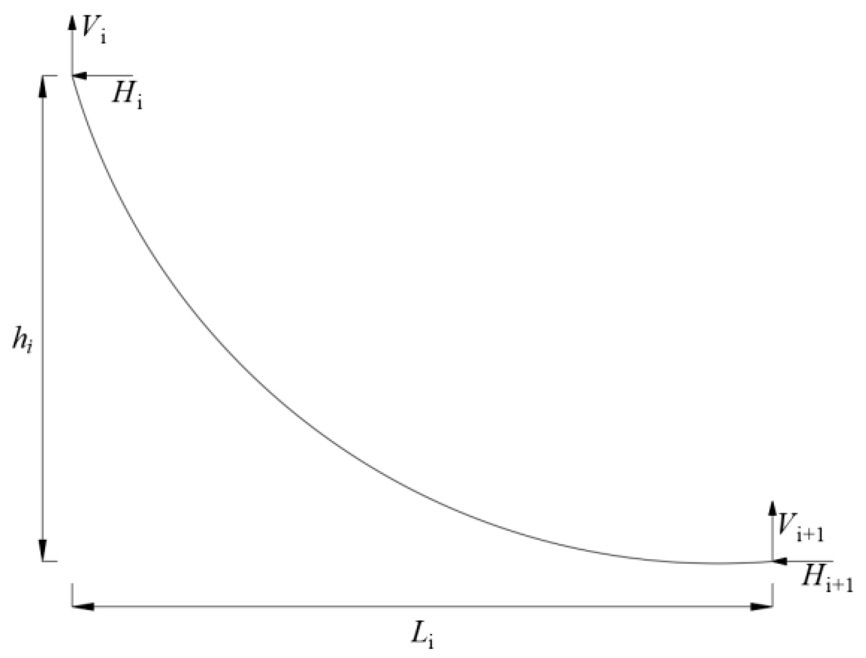
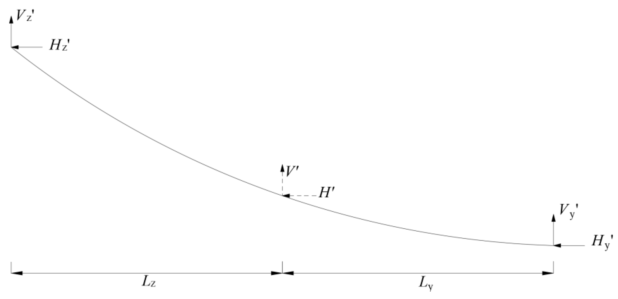
2.1. The Catenary Principle

Based on the catenary principle, this paper carries out an in-depth analysis of the deformation changes of the main cable after the removal of the suspender. A section of suspension cable between the main cable sling is taken, and the unit cable length weight is, as shown in Figure 1.
The variation of main cable length of self-anchored suspension bridge is very small, which is negligible compared with the total length. Any cable section between slings should conform to the actual situation [22,23]:
L i 1 = H q s h 1 V i 1 H s h 1 V i q s i 1 H
The distance between the suspenders is usually equal, so the vertical component of the vertical rod can be obtained:
V i = V i 1 T i q s i 1
According to Equation (1), by setting e q L H = a , the vertical component forces on the left and right sides of the catenary micro-segment can be solved.
V i 1 l = q s i 1 2 + H ( s i 1 L ) 2 1 ,   Left   side   high ,   right   side   low V i 1 r = q s i 1 2 H s i 1 L 2 1 ,   Right   side   high ,   left   side   low
According to the segmented catenary theory, when the suspender exits the work, the adjacent two ends will merge into a section due to the role of the bridge’s weight, as shown in Figure 2.
After a single section is taken out, the boundary condition on both sides is consolidation, and the force component of the main cable of the rail suspension bridge can be approximated. Due to the linear relationship between the component force and the length of the unstressed cable, the cable force at this point can be redistributed according to the length. The displacement method is used to solve the new vertical and horizontal component force after the removal of the suspender:
V Z = q s z + V + s y s z + s y · T
H z = q s z + 2 V + 2 s y s z + s y T 2 s z 2 L 2 · L

2.2. Main Cable Deformation Safety Index

Based on the above analysis, after the removal of the suspender, the main cable will have a phenomenon of upward torsion due to the loss of support points. The vertical component of the adjacent main cable nodes before and after the removal of the suspender can be obtained by Formula (4), namely:
Δ V = q s z + V + s y s z + s y · T q s i 1 2 H ( s i 1 L ) 2 1
After the suspender is removed, the length of the newly stress-free cable segment will change, and the change in cable length can be obtained:
Δ s = Δ V · s E · A
where: s stress-free length of the main cable; E is the elastic modulus of the main cable material; A Cross-sectional area of the main cable.
The displacement of the main cable can be solved from a macroscopic point of view through the vector span ratio and cable length change:
Δ y = Δ V · s E · A · f L
where: f Sag of the main cable; L is the distance between suspender points.
Because the displacement of the main cable at the removal of the lifting point is not easy to control, according to the Technical Regulations for the Removal of Highway Concrete Bridges’ 4.4.15 [24] and Article 6.2.10a of the Technical Specifications for the Operation and Monitoring of Urban Rail Transit Facilities Part 2: Bridges [S] [14]: The deformation monitoring value should be less than or equal to the theoretical calculation value corresponding to the deformation, and the safety index of adjacent main cable nodes is proposed:
Y s Y x 10   ( mm ) ,   Static   load f s f M 0 ,   Train   load
where: Y s is the displacement of adjacent nodes of the upstream main cable; Y x is the displacement of adjacent nodes of the downstream; f s is the current monitoring value; f M is the maximum theoretical value.

2.3. Cable Force Safety Index

According to the weak coherence principle of the main cable displacement, when the cable force T changes, the left and right lifting points will get a new horizontal component force H z , and a new cable force T i can be calculated by H z , namely:
T i = T j + Δ T j
where: T j is the initial cable face value; Δ T j is the change value due to the removal of the suspender.
Based on the continuous setting of the main cable, the newly distributed cable force Δ j on the left and right sides is analyzed using the energy method according to the principle of the influence of adjacent lifts. According to the law of conservation of energy, it can be obtained:
T i · Δ L j = Δ L j 1 · Δ T j 1 + Δ L j + 1 · Δ T j + 1
Δ L j = T j · L 1 A · E
where: Δ L j is the displacement amount after absorbing energy; Δ T j is the component of cable force; L 1 is the length of the suspender; A is the cross-sectional area of the displacement node; E is the elastic modulus of section.
According to the force-displacement relationship is linear:
Δ T j 1 = K j 1 · Δ L j 1 Δ T j + 1 = K j + 1 · Δ L j + 1
where: K refers to the stiffness of the suspender.
The distance between the suspender rods of the suspension bridge is usually equal, and the expression of the displacement of the left and right nodes can be obtained:
Δ L j 1 = s y s z + s y · Δ L j Δ L j + 1 = s z s z + s y · Δ L j
By bringing the above information about Δ L j 1 and Δ L j + 1 into the energy conservation equation, the Δ L j can be obtained:
T i = ( K j 1 · s y s z + s y · Δ L j + K j + 1 · s z s z + s y · Δ L j ) · Δ L j
Δ L j = T i K j 1 · s y s z + s y · Δ L j + K j + 1 · s z s z + s y · Δ L j
Therefore, the distribution of sling force on either side (left) is, and the same is true for the right side:
Δ T j 1 = K j 1 · s y s z + s y · T i K j 1 · s y s z + s y · Δ L j + K j + 1 · s z s z + s y · Δ L j
The approximate value of adjacent cable force change of the track suspension bridge can be solved by Formula (17), and the rate of change can be solved by combining the initial cable force of the bridge (taking the left side as an example), as shown in Equation (18):
R v = Δ T j 1 T j · 100 %
Further, according to Article 10.1.1 of Code for Design of Highway Suspension Bridges [16] and Article 6.2.10a of Technical Code for Operation Monitoring of Urban Rail Transit Facilities Part 2: Bridges [S] [14]: The monitoring value of cable force should be less than or equal to the product of the reduction coefficient of the corresponding theoretical calculation value of cable force and the theoretical calculation value of cable force, and the safety index of cable force replacement under the unsupported replacement method is proposed:
T G T i K S = 2 ,   Static   load P σ γ · M σ ,   Train   load
where: K S is the safety factor; T G is the ultimate cable force; T i is the current cable force; P σ is the upper limit of adjacent cable force monitoring; M σ is the theoretical calculation value of the current cable force; γ is the reduction coefficient of cable force, the range is [0.95~1.00], 0.95 is taken in this research.

2.4. Theoretical Analysis of Deformation of Stiffening Beam

2.4.1. Calculation Assumption

Under the condition that the anchor point of the main cable of the self-anchored rail suspension bridge is ensured to be continuous with the stiffened beam, the main cable is concentrated on the stiffened beam, so that the stiffened beam will generate huge axial force [25]. Secondly, more prestress is applied based on the ordinary stiffened beam, so that the flexure stiffness of the stiffened beam can be amplified again so that there is enough redundancy to resist the uneven instantaneous load. Meanwhile, the bending deformation of the stiffened beam is verified by increasing the dead load and variable load [26], and the overall stability coefficient is 4.3, which proves that the stiffened beam will not appear local buckling even if the overall instability occurs [25]. In the calculation process, the stiffened beam of the rail suspension bridge is assumed to be a small deformation, that is, the deformation of the stiffened beam will not affect the structural safety.

2.4.2. Safety Index of Displacement of the Stiffened Beam

When the suspender is removed without support, the stiffened beam will produce displacement under the action of the structure’s weight. Therefore, according to Hooke’s law, the simplified model is used to calculate the displacement of the bridge deck with dismantled nodes, namely:
Δ H = T j · L 1 E 1 · A 1 + K l + α · E x · A x L x
When the suspender is cut for the first time, the section area is reduced by Δ A 1 . In the process of the bridge floor system lowering, the stiffness of the adjacent suspender and the stiffened beam will participate in the force together, so α is introduced to represent the constraint of the adjacent suspender on the displacement. At this time, the bridge floor system is reduced by Δ H 1 , and there are:
Δ H 1 = T j · L 1 E 1 · A 1 Δ A 1 + K l + α · E x · A x L x T j · L 1 E 1 · A 1 + K l + α · E x · A x L x
For the second cutting, the section area is reduced by Δ A 1 + Δ A 2 , and the bridge deck system is reduced by Δ H 2 , then:
Δ H 2 = T j · L 1 E 1 · A 1 Δ A 1 + Δ A 2 + K l + α · E x · A x L x T j · L 1 E 1 · A 1 Δ A 1 + K l + α · E x · A x L x
In this way, when the suspender is cut n times, the remaining area of the suspender is A 1 Δ A 1 Δ A n 1 , and the displacement of the stiffening beam is:
Δ H n = T j · L 1 E 1 · A 1 i = 1 n Δ A i + K l + α · E x · A x L x T j · L 1 E 1 · A 1 i = 1 n 1 Δ A i + K l + α · E x · A x L x
In total, the cumulative displacement generated by the stiffened beam after the first cut to the n cut is:
Δ H a l l = Δ H 1 + Δ H 2 + + Δ H n
where: L 1 is the length of the suspender; A 1 is the cross-sectional area; Δ A 1 is the first cutting area; E 1 is the elastic modulus; K l is the extra stiffness of the stiffened beam; α is the displacement coefficient of the stiffening beam controlled by the suspender; E x , L x , A x indicate the parameters of adjacent suspenders.
According to sections 6.2.10b and 7.3.2 of Technical Specifications for Operation Monitoring of Urban Rail Transit Facilities [14] and reference [27], safety indexes of stiffened beams for short rod replacement under unsupported replacement method are proposed:
B σ B 0 ,   Static   load Δ H L 600 = 1.0   m ,   Train   load
where: Δ H is the elevation of the stiffened beam after the removal of the suspender; L is the span, the main span of the bridge is 600 m; B σ is the monitoring displacement and deformation value; B is the theoretical maximum deformation value.

3. Project Background

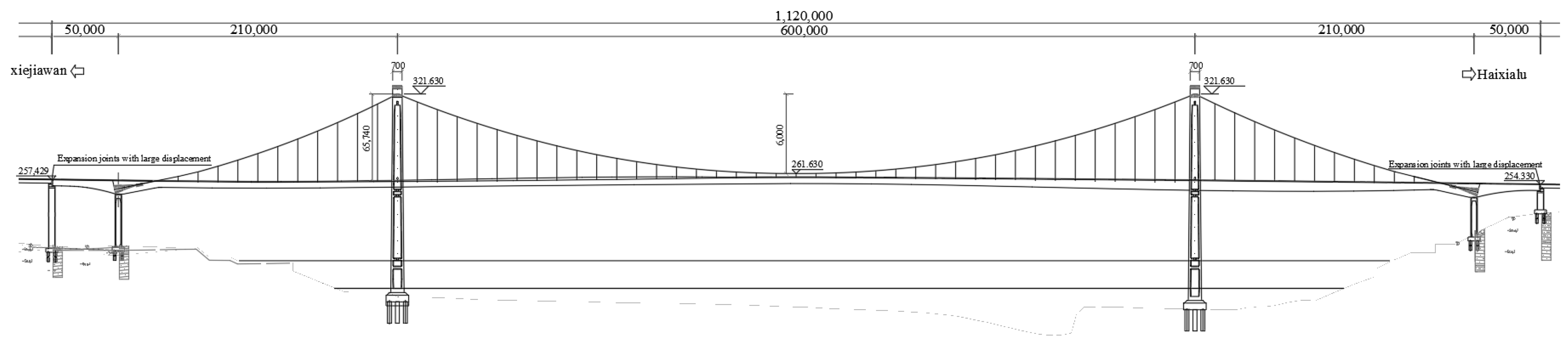
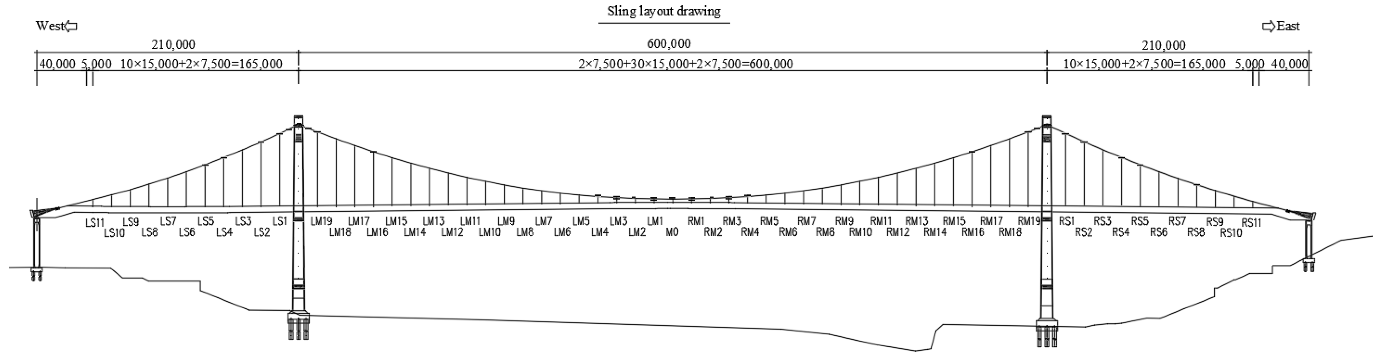
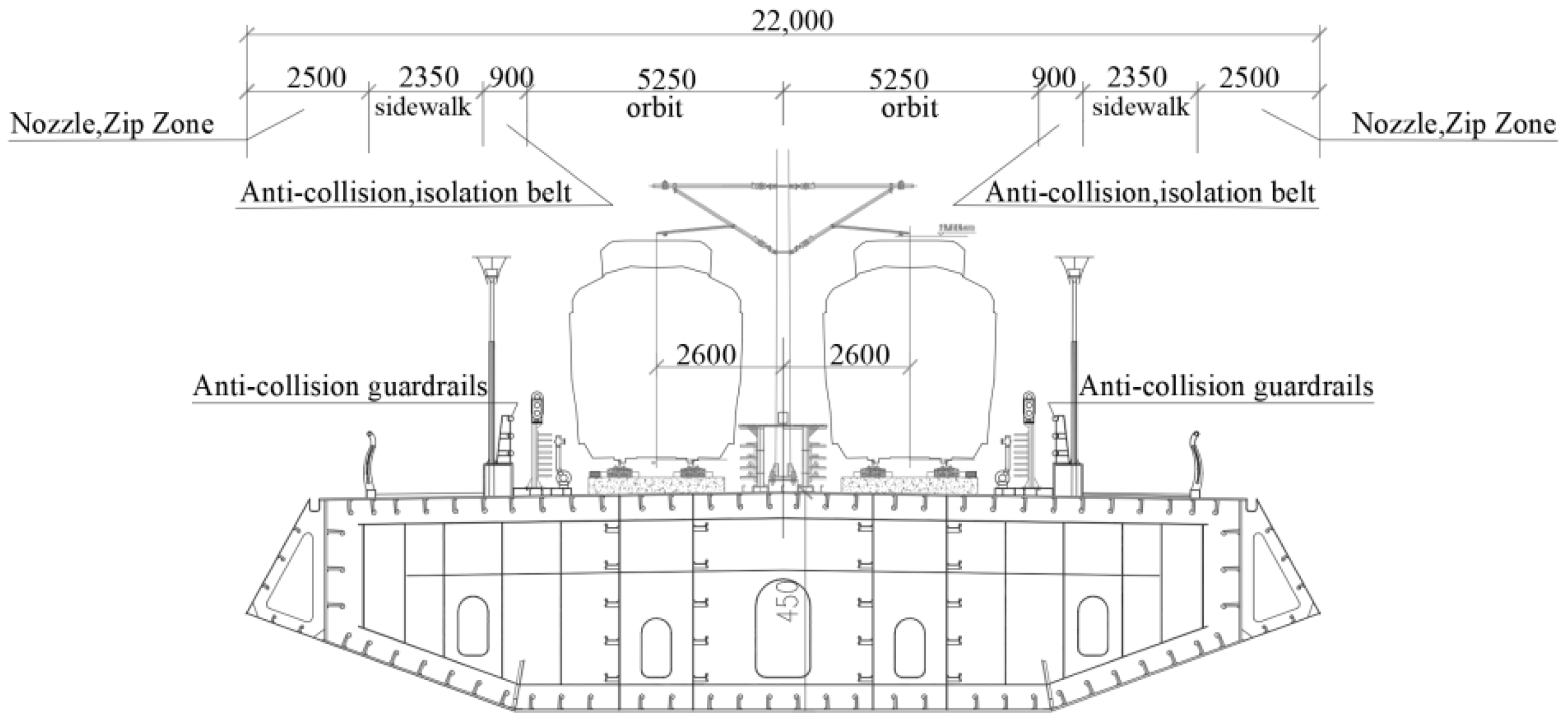
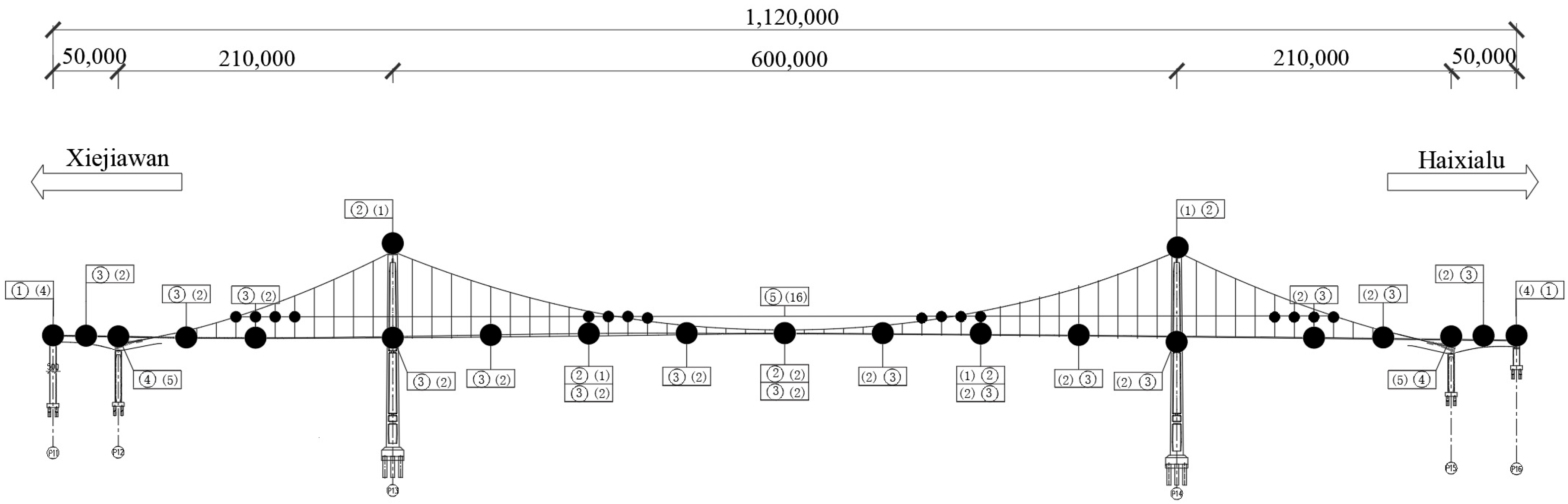
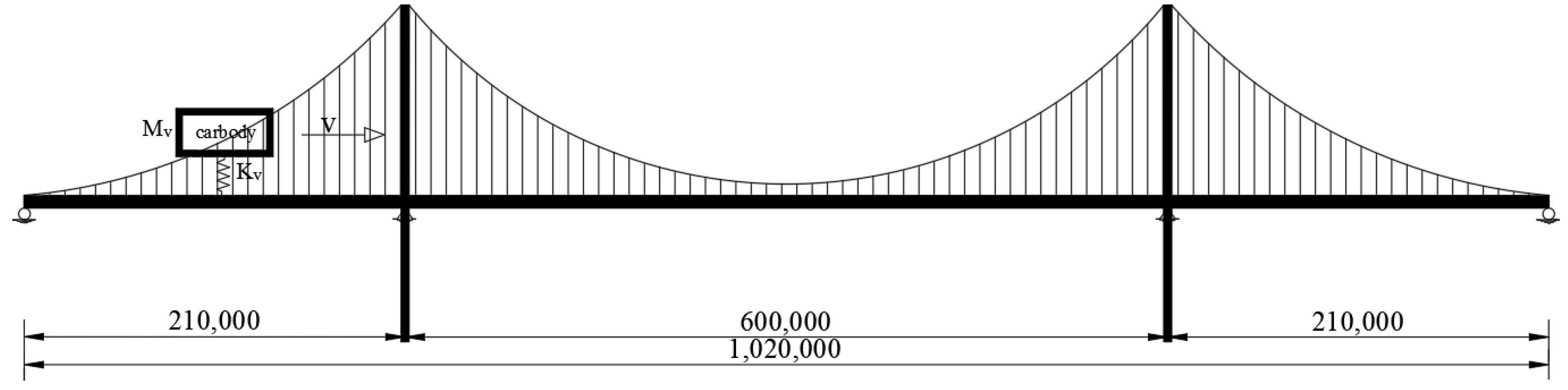
3.1. Project Overview

Chongqing Egongyan Rail-transit Bridge is the world’s largest self-anchored railway special suspension bridge. Its main bridge adopts a unique 5-span self-anchored suspension bridge structure with a span combination of (50 + 210 + 600 + 210 + 50) m. The main cable is composed of 2 cables, each of which contains 92 strands, and each strand is composed of 127ϕ5.2 mm zinc-aluminum alloy coated high-strength steel wire. The hot-cast anchor has a total of 11,557 wires, the tensile strength of steel wire is σ b 1860   M P a , the yield strength is σ 0.2 1660   M P a , and the anchor is anchored at the end of the stiffened beam of the main bridge, and the overall safety factor is K S > 2.5 . The suspenders is made of ϕ7 mm galvanized high-strength and low-relaxation parallel steel wire with PE material. There are 122 lifting points in the whole bridge, and the tensile strength of the steel wire is σ b 1770   M P a , and the yield strength is σ 0.2 1580   M P a . The upper end is connected with the main cable clip by pin hinge, and the lower end is connected with the main beam using anchor box pressure. Overall safety factor K S > 3.0 ; The stiffened beam adopts the composite structure of steel beam and concrete beam, specifically the single-box three-compartment prestressed reinforced concrete continuous beam box beam style, and its bridge floor width is distributed as follows: B = 2.25 (cable area, air nozzles) + 0.25 (railing) + 2.35 (sidewalk) + 0.9 (anti-collision, isolation belt) + 10.5 (rail boundary) + 0.9 (anti-collision, isolation belt) + 2.35 (sidewalk) + 0.25 (railing) + 2.25 (cable area, air nozzles) = 22.0 m. The bridge layout, main beam section, main tower section, main cable, and suspender section are shown in Figure 3, Figure 4, Figure 5, Figure 6, Figure 7, Figure 8 and Figure 9.

3.2. Structural Deformation and Cable Force Monitoring System

The monitoring system for structural deformation and cable force of the Chongqing Egongyan Rail-transit Bridge is mainly composed of the following five parts: (1) moving load monitoring, (2) spatial deformation of the main bridge, (3) vertical deformation of the stiffening beam, (4) main cable force, (5) suspender cable force. The long-term health monitoring system is mainly composed of five major systems, namely, the sensor subsystem, data acquisition and transmission subsystem, data processing and analysis subsystem, data storage and management subsystem, early warning subsystem, and sensor system. The structural response data are collected through the field sensor and uploaded to the system platform through the transmission system. Data processing, analysis, and storage are carried out on the platform, and timely warnings are issued once the limits are exceeded. The general arrangement of the structural deformation and cable force monitoring system for the Chongqing Egongyan Rail-transit Bridge is shown in Figure 10. The information on the monitoring equipment is shown in Table 1.

3.3. Finite Element Analysis

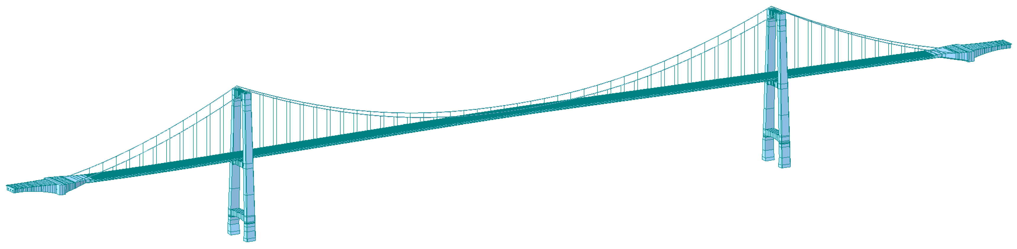
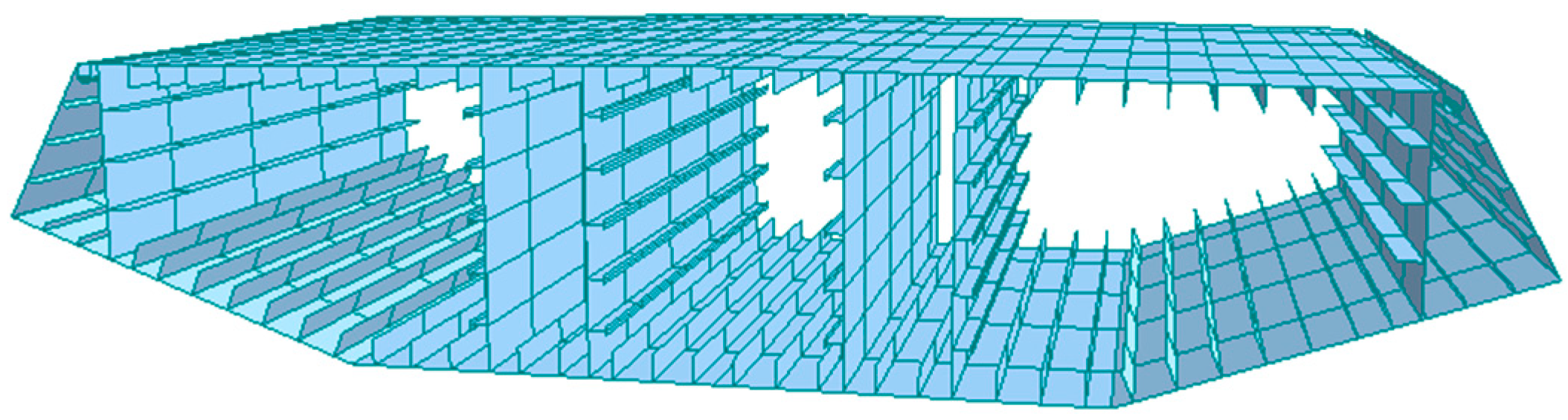
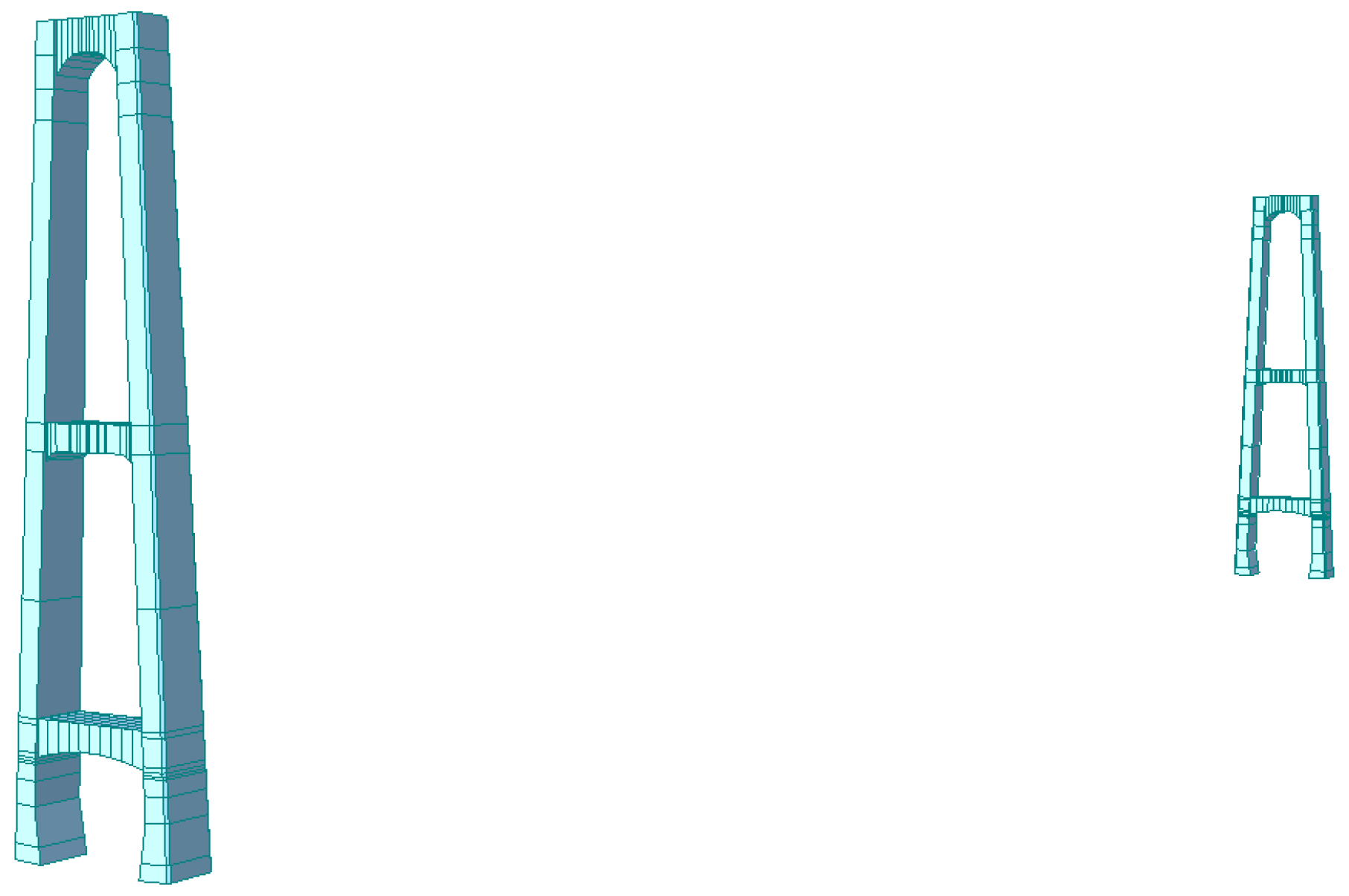
3.3.1. Finite Element Model
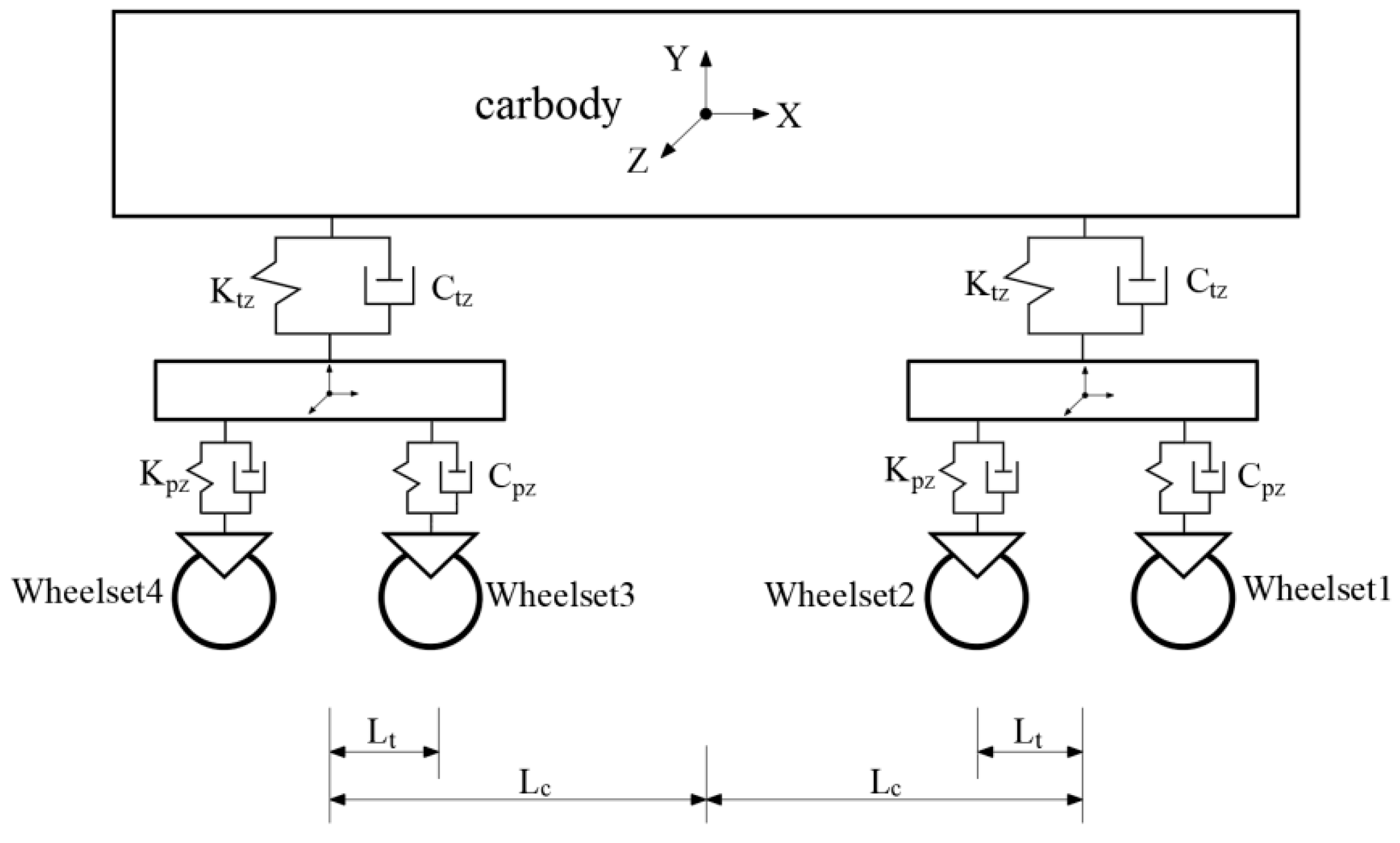
Midas Civil 2024 was used to establish a numerical analysis model for the Chongqing Egongyan Rail-transit Bridge. The model was divided into 937 nodes and 924 units (674 beam units and 250 tension units only). The main beam and bridge tower are simulated by the beam element, and the main cable and suspender are simulated by the tension truss element only. According to the actual situation of the bridge structure, the boundary and constraint conditions of the finite element model are set as follows: fixed supports are set at the bottom of the bridge tower; The main beam and the main cable anchor point, the main beam and the lower edge of the suspender, the main cable, and the main tower are rigidly connected. The elastic connection between the main beam and the support of the bridge tower is simulated, and the longitudinal direction of the bridge is not constrained. The main beam at the auxiliary pier and junction pier adopts general support to release longitudinal constraints. The model is shown in Figure 11, Figure 12, Figure 13 and Figure 14, and the main component characteristic parameters are shown in Table 2.

3.3.2. Train Model

The design of the Chongqing Egongyan Rail-transit Bridge adopts As train, which considers a 6-section formation in the near term and an 8-section formation in the long term, with an axle weight of 150 kN. This research takes the recently operated 6-section formation train as the model and analyzes the load condition considering full load. The train length is 19.3 m, the train width is 3 m, the train distance is 13.4 m and the axle weight is 150 kN. When fully loaded, the weight of the train is 360 t. According to the general code for the design of highway Bridges and culverts [28], the load of the 6-car train is placed in the middle span of the bridge structure for analysis. The diagram of train loading, single train, and train crossing the bridge are shown in Figure 15, Figure 16 and Figure 17.

3.3.3. Model Verification

In order to verify the accuracy of the established Midas Civil model, the cable force data collected by the side span LS6 and RS6 booms and the mid-span LM7 and RM7 booms over a 7-day period with a large passenger flow were selected and compared with the simulation results of the finite element model (FE) to verify the accuracy of the model, as shown in Table 3 and Table 4. The scientificity and feasibility of this verification method have been widely used in bridge health monitoring systems.
According to the comparison of Table 3 and Table 4, the match degree between the measured values of LS6 and RS7 and the theoretical values is the highest 97%, the match degree between LM7 and RM7 is the highest 99%, and the average fit degree between the measured values and the theoretical values of the four suspender cable forces is 96%. According to the monitoring value of cable force/theoretical calculation value of cable force mentioned in the specification [14], it can be considered reasonable if it is kept between [0.95 and 1.00]; otherwise, the model should be revised.

4. Experiment and Discussion

4.1. Structural Response Analysis Under Static State

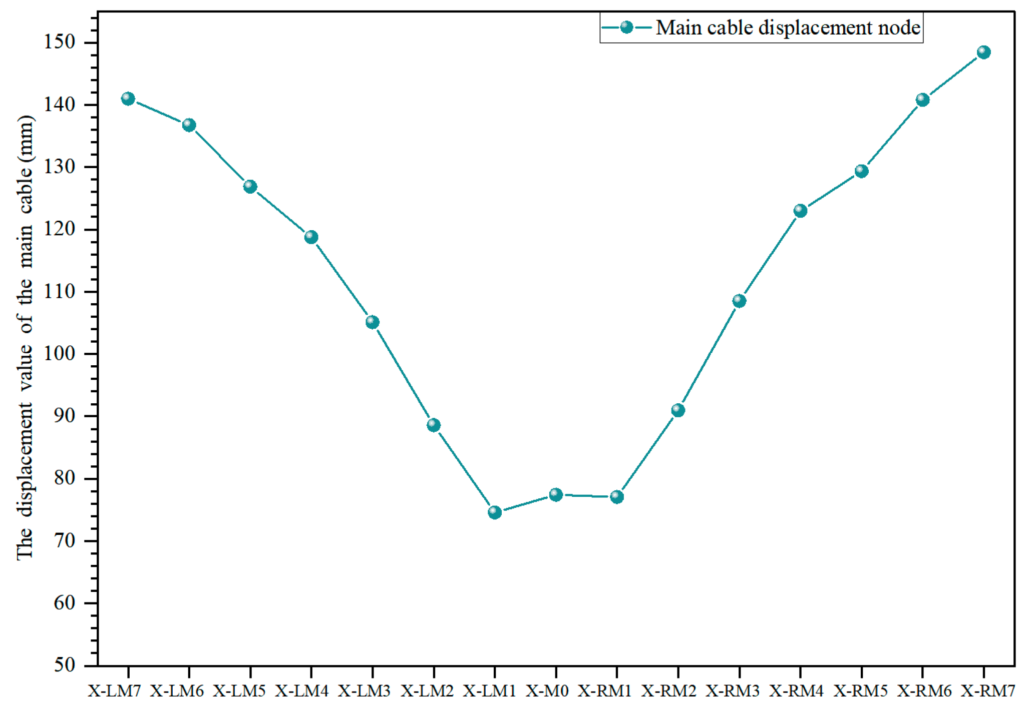
4.1.1. Main Cable Deformation Analysis

The replacement method proposed in this paper has been studied for the first time in the track suspension bridge, in order to clarify the influence of this method on the different side in service boom and related beam and cable joints during construction. According to the relevant literature, the order of derrick replacement is short rod first, then long rod, and middle span first in side span. Therefore, the numerical simulation analysis is carried out with 15 short rods in the middle and lower reaches of the mid-span span as the removal objects, and one derrick is removed as one working condition, with a total of 15 working conditions, as shown in Table 5. To further explore the structural response characteristics after the removal of the suspender, the deformation of the main cable nodes and adjacent nodes under the removal of the suspender in working conditions 1 to 15 was accurately calculated, as shown in Figure 18 and Table 6. Because of the integrity and correlation of the structural system, the potential impact of the removal of the downstream suspender on the displacement of the upstream main cable was fully considered, and special calculations were carried out, as shown in Figure 19.
As shown in Figure 18, at the point where the short suspender is removed, the main cable presents different degrees of upward torsion, and its displacement ranges from 100.69 mm to 152.09 mm. After the removal of the suspender, the corresponding position lacks the restraint effect exerted by the original suspender, and under the continuous action of the inertial force, the original stress balance state of the main cable system is broken, resulting in the torsion deformation of the main cable.
As can be seen from Table 6, under different working conditions, the suspender and its adjacent nodes present specific deformation rules. Under working conditions 5~8, for the adjacent suspender on the east side (R side) of the replacement node, there is a down torsion phenomenon, and its down torsion displacement is between −0.10 mm and −0.01 mm. Under working conditions 8~11, the adjacent suspender on the west side (L side) of the replacement node also has a down torsion condition, and the deflection range is from −0.11 mm to −0.01 mm. In addition, in other working conditions, the corresponding adjacent nodes are shown as warping, and the warping displacement is in the range from 0.3 mm to 4.72 mm. It can be seen that the whole process of suspender replacement does not lead to the deformation of the adjacent nodes of the corresponding nodes on the non-replacement side.
As can be seen from Figure 19, after the removal of the downstream suspender, the upstream test node has an average down torsion of −6.79 mm, which proves that the replacement of the side suspender will cause down torsion of the corresponding node on the other side, and its down torsion displacement is in the range of −8.26 mm to −4.91 mm, and there are certain differences in the degree of down torsion of each node. At the same time, according to the initial height difference of 5.72 mm between LM7 and RM7 in the completed bridge state, it is further found that the down torsion of the east (R) west (L) side is only 0.1 mm different. It can be seen that the down-warping amplitude of the main cable is not affected by the initial height difference of the completed bridge, and factors such as the redistribution of force caused by the removal of the suspender play a leading role in the down-warping of the main cable, while the existing condition of the height difference of the completed bridge is relatively secondary.

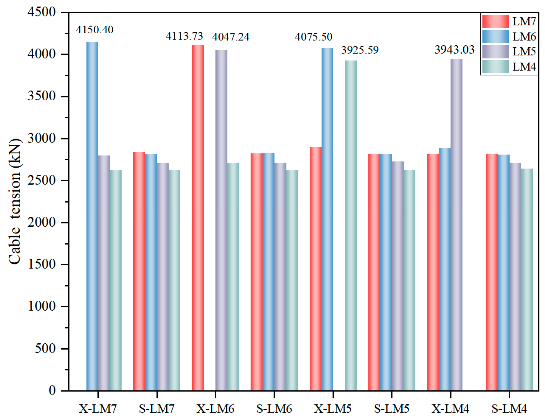
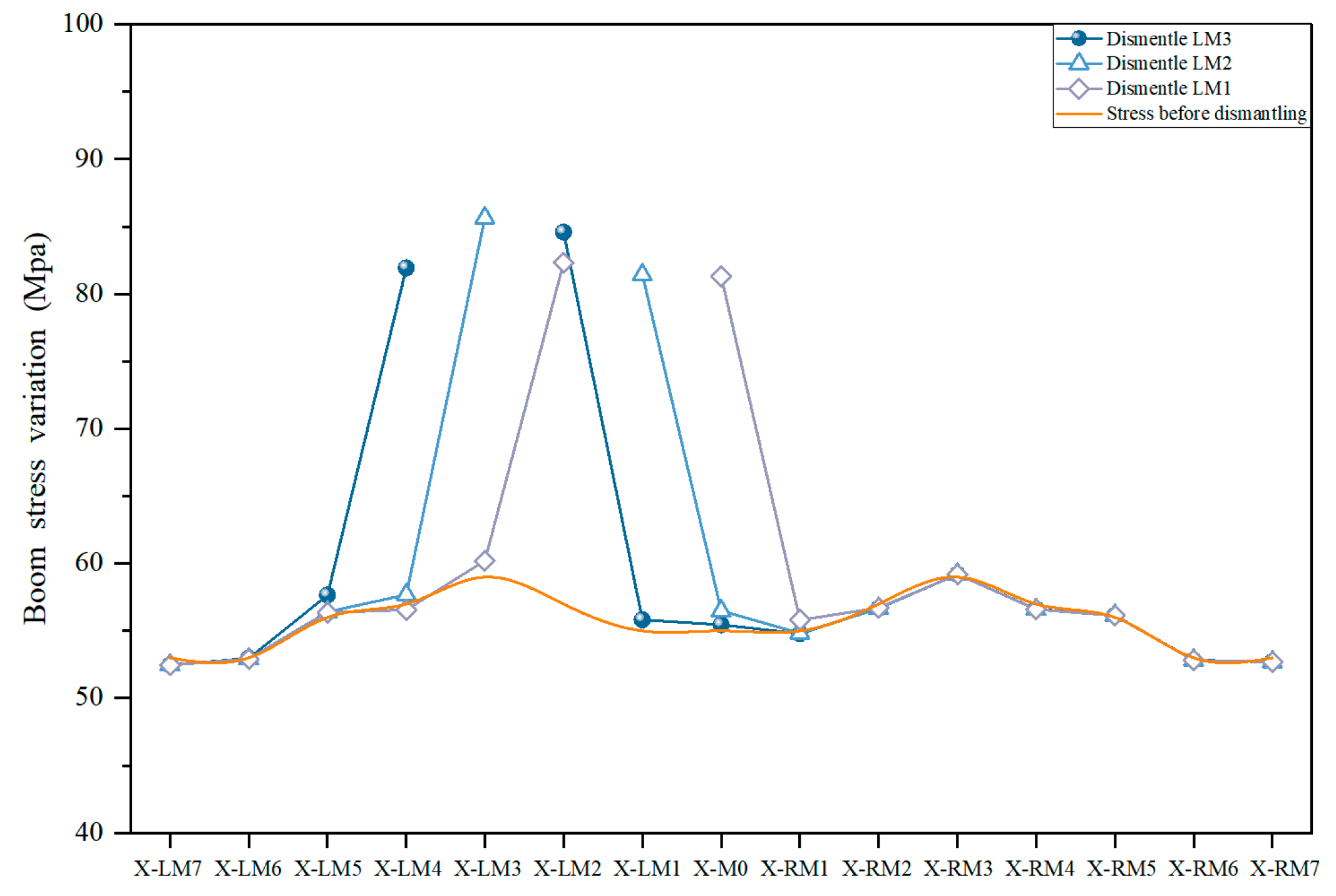
4.1.2. Incremental Analysis of Cable Force of the Adjacent Suspender

Based on Midas Civil finite element analysis software, a numerical simulation analysis was carried out on the unsupported replacement suspenders, and the cable force of adjacent rods of the dismantled suspender was extracted for analysis. The changes of cable force were analyzed with the downstream suspender as the object, and the results are shown in Figure 20. Meanwhile, taking LM7-LM4 as the object, the influence of suspender removal on the cable force of short poles in service on different sides is analyzed, as shown in Figure 21.
As can be seen from Figure 20, under working conditions 1 to 15, after the suspender is removed, the cable force of the adjacent rods presents a surging trend, with an incremental fluctuation ranging from 922.2 kN to 1355.1 kN, depending on the removal location. Among them, the cable force increment is the largest in working condition 15, when the suspender RM7 is removed, the cable force increment of the adjacent suspender RM6 is 1355.1 kN; The cable force increment is the smallest in working condition 2. When the suspender LM1 is removed, the cable force increment of the adjacent suspender LM2 is only 922.2 kN. Because the adjacent suspender shares the internal force generated by removing the joint, when a suspender is removed, the cable force of the adjacent suspender within one unit away from the east and west sides will increase by 42%~55%. However, the cable force of the suspender of the two units on the east and west sides of the dismantled node only increases by 3%. The influence gradually decreases with the increase of the distance, and finally can be ignored. It can be seen that the influence of the removal of the suspender on the structure has obvious spatial distribution characteristics, and the increase of the cable force of the member farther away from the removal of the suspender is small, reflecting the effect of force redistribution and stress concentration. The force propagation is mainly concentrated near the demolition point, while the force variation of the part far away from the demolition point is small.
It can be seen from Figure 21 that in working conditions 1 to 4, the cable force of the adjacent suspender on the same side after the suspender is removed increases by an average of 1295.33 kN, an increase of about 47%, which is consistent with the phenomenon in Figure 17. When the suspender is removed, the removal side has little influence on the corresponding nodes on the opposite side, and the average cable force change is only 19.47 kN, with an increase of about 0.7%. The cable force increase of the adjacent suspender on the opposite side is only 3.71 kN on average, an increase of about 0.14%. The results show that the removal of the suspender has very limited influence on the non-removal side, especially on the opposite side joints and its adjacent suspender, and the stress is mainly concentrated near the removal point.

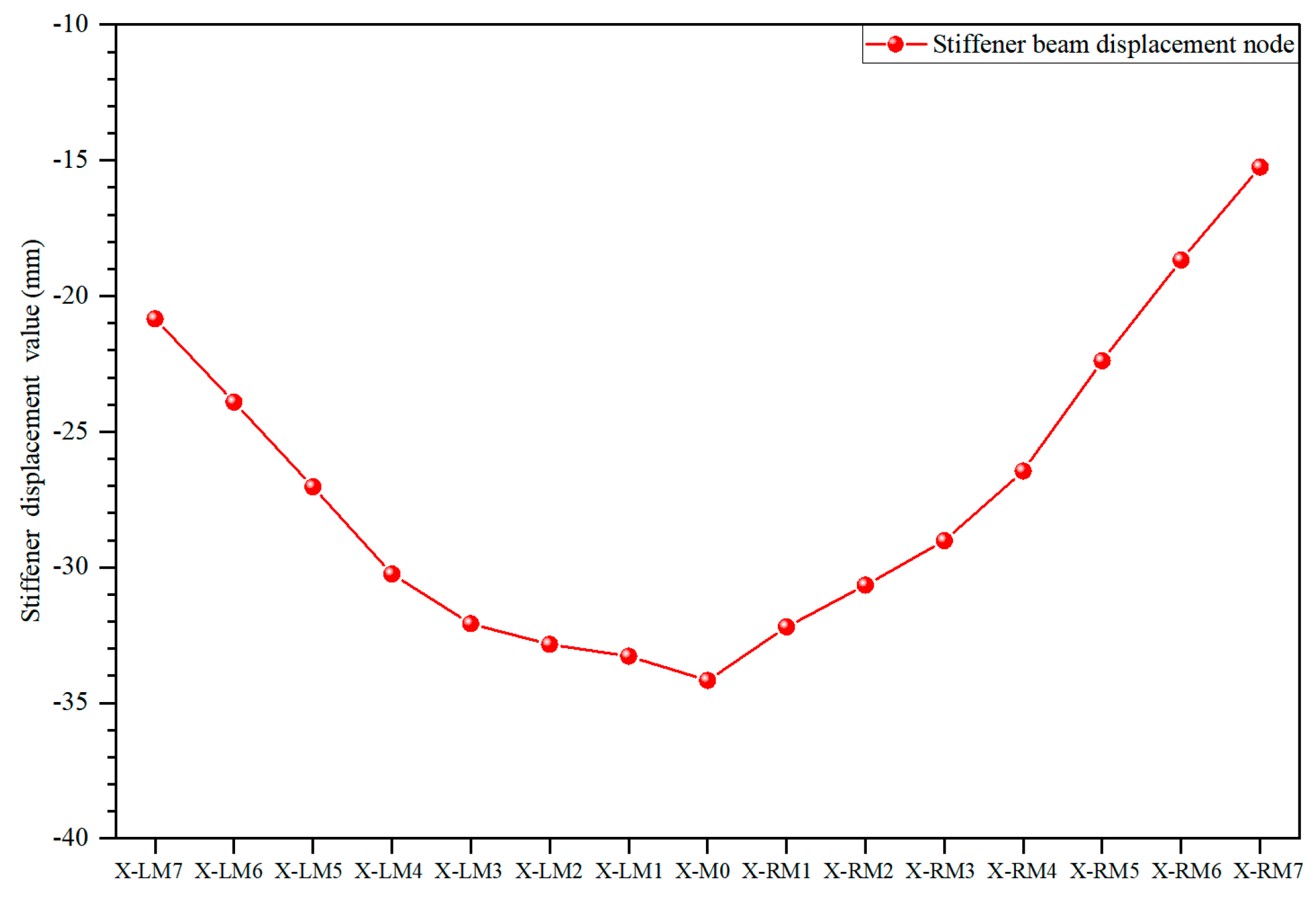
4.1.3. Deformation Analysis of Stiffened Beam

Given the structural characteristics after the removal of the suspender, the detailed calculation of the main beam nodes and their adjacent nodes is carried out, as shown in Figure 22 and Table 7. Given the integrity of the structural system and the potential mechanical correlation between the upstream and downstream, the impact of the removal of the downstream suspender on the displacement of the upstream main beam is fully considered, and special calculations and analyses are carried out, as shown in Figure 23.
As can be seen from Figure 22, when a single suspender exits the work, the joints of the stiffened beam will produce displacement changes of different degrees, ranging from −11.73 mm to 7.44 mm. In the whole beam system structure, the suspender assumes a very critical constraint and force transmission function. Once a single suspender fails to work, it will break the original force balance state, resulting in significant changes in the stress state of the stiffened beam node close to the suspender, and then trigger the corresponding displacement response.
As can be seen from Table 7, under specific working conditions, the adjacent beam joints present a displacement variation range from −8.28 mm to −4.65 mm. In the same working condition, when the suspender is removed, under the action of the structure’s self-weight, the vertical displacement value generated by the beam joint at the removal point of the suspender is the largest, and it will still be significantly affected within 8 units from the removal node, with the maximum influence value reaching −8.17 mm. However, once the distance of 8 units is exceeded, this effect is dramatically reduced to a maximum of −0.9 mm, which is relatively small and has negligible impact on the overall structural performance and subsequent analysis. It can be seen that the effect of the removal of the suspender on the joint of the beam system has obvious spatial attenuation characteristics. In the area near the dismantled node, the deformation response of the structure is more severe because the force transfer and redistribution are more concentrated. With the increase of the distance, the force transfer gradually disperses and dissipates, and the influence on the joint of the beam system decreases rapidly.
As can be seen from Figure 23, after the suspender exits the working, the stiffening beam on the opposite side of the removed node presents a downflex phenomenon from −8.46 mm to −5.46 mm. Replacing the missing side suspender will cause corresponding changes in the displacement of the opposite side, and there is a close mechanical correlation and interaction among all parts of the structure. When the initial height difference between LM7 and RM7 is 5.74 mm, the down warping on the east (R) and west (L) sides are analyzed, and the results show that the difference between the two sides is only 0.1 mm, which is consistent with the analysis in Figure 16. In summary, the down torsion amplitude of the stiffened beam is not restricted by the initial height difference of the bridge, and the deformation response of the whole structure caused by the change of local members mainly depends on the redistribution and transfer mechanism of the force.

4.2. Structural Response Analysis of Train Under Full Load

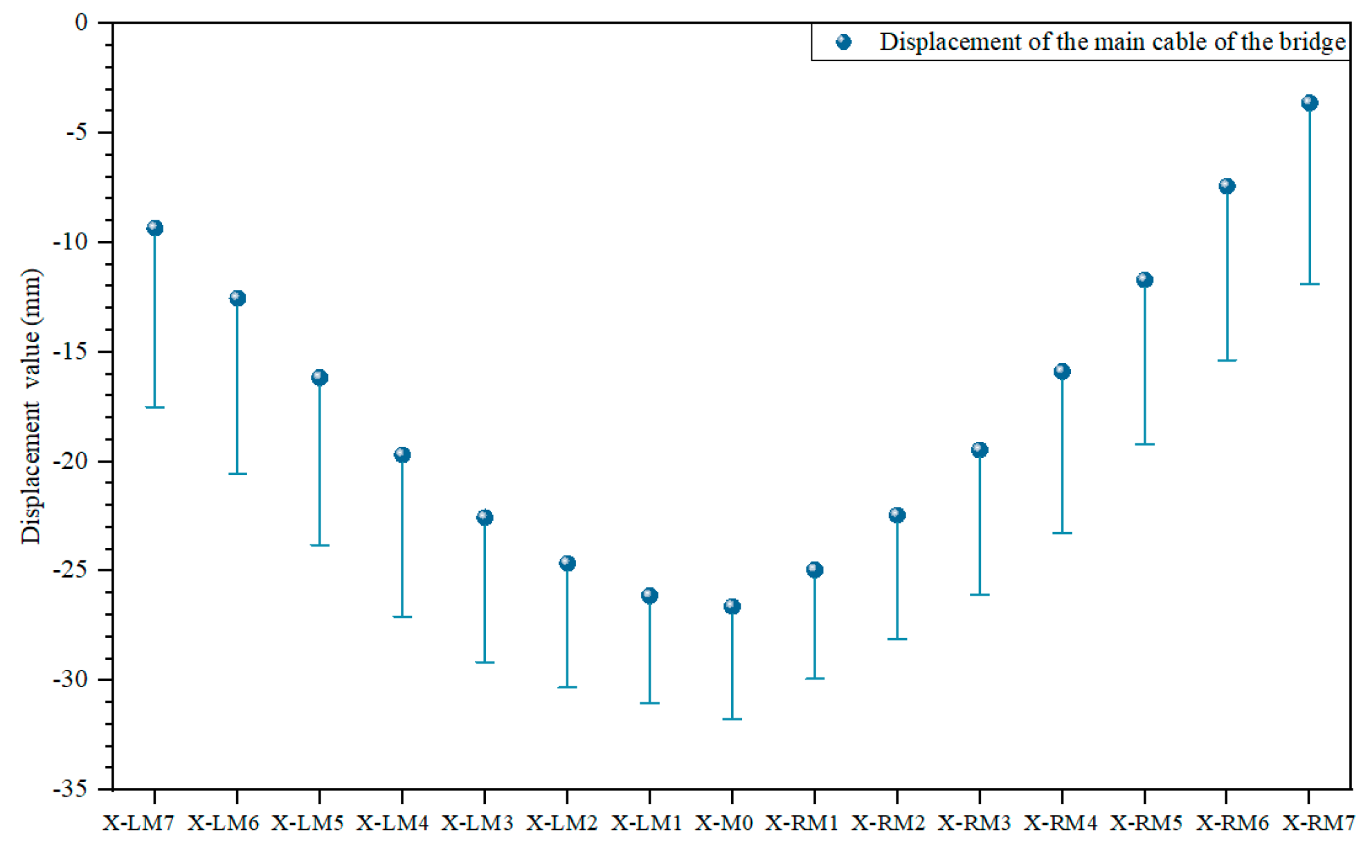
4.2.1. Main Cable Deformation Analysis

The round-trip train was fully loaded and the load was set at 360 t as the most unfavorable load condition, and the main cable deformation during replacement and non-replacement was analyzed. The calculation results are shown in Figure 24.
As can be seen from Figure 24, when the suspender is not replaced, the theoretical maximum downflex value of the most unfavorable load node of the main cable reaches −739.84 mm and −741.34 mm, respectively. However, when the unsupported replacement method is used to replace the suspender, the down torsion of the most unfavorable nodes on both sides of the corresponding joint changes to −723.42 mm and −724.87 mm, and the maximum difference between them is only 16.54 mm, with an increase rate of 2.22%. This small difference fully indicates that the effect of the unbraced replacement method on the main cable during the implementation is very low and almost negligible.

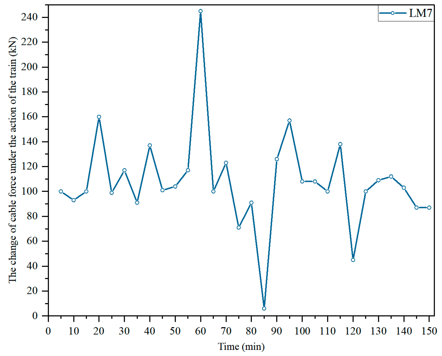
4.2.2. Incremental Analysis of Cable Force of the Adjacent Suspender

According to the most unfavorable load setting of railway suspension bridge, the change of cable force and stress state of the adjacent suspender during train operation after the removal of the suspender are deeply analyzed. The three suspenders with the largest adjacent cable force increment are selected as objects for detailed analysis, and the corresponding analysis results are shown in Figure 25.
As can be seen from Figure 25, after the removal of three different suspenders X-LM1, X-LM2, and X-LM3, the cable forces of adjacent rods of the removed suspender all showed an extremely significant upward trend. Compared with the data when the structure is in normal use, the maximum value of the cable force increase can reach 150.0 kN, which exceeds 49% compared with the upper limit of the envelope value. The removal of the suspender has a very strong deformation effect on the cable force distribution of the adjacent rod. However, the suspender in its conventional use cycle mainly bears the role of tension. The design tensile strength of the suspender is as high as 1770 MPa, which gives the suspender excellent bearing capacity. Even in the special and extreme working conditions of the suspender removal, when the structure is in a state unsupported, the material properties of the suspender itself can still effectively adapt to the sudden increase in cable force due to structural changes. At the same time, according to the relevant research results in the references [29,30] on the suspender which failed to reach the maximum stress after breaking, the object in this study further proves that it still can continue to bear the load even in the adverse situation that the cable force greatly increases due to the lack of short suspenders.
As can be seen from Figure 26, the average stress level of the suspender under operation is about 55 MPa. When a suspender exits from work, the stress of the adjacent suspender will increase to a certain extent, and its added value is in the range from 23.5 MPa to 27 MPa. The sum calculation of the increased stress and the original stress in the operating state shows that the result is far lower than the design strength of the suspender, which proves that under the current structural system and working conditions, even if one suspender stops working and causes the stress of the adjacent suspender to rise, the overall structure still has enough safety margin to effectively maintain its structural integrity and stability. It will not cause structural failure or lack of strength due to changes in the local suspender.

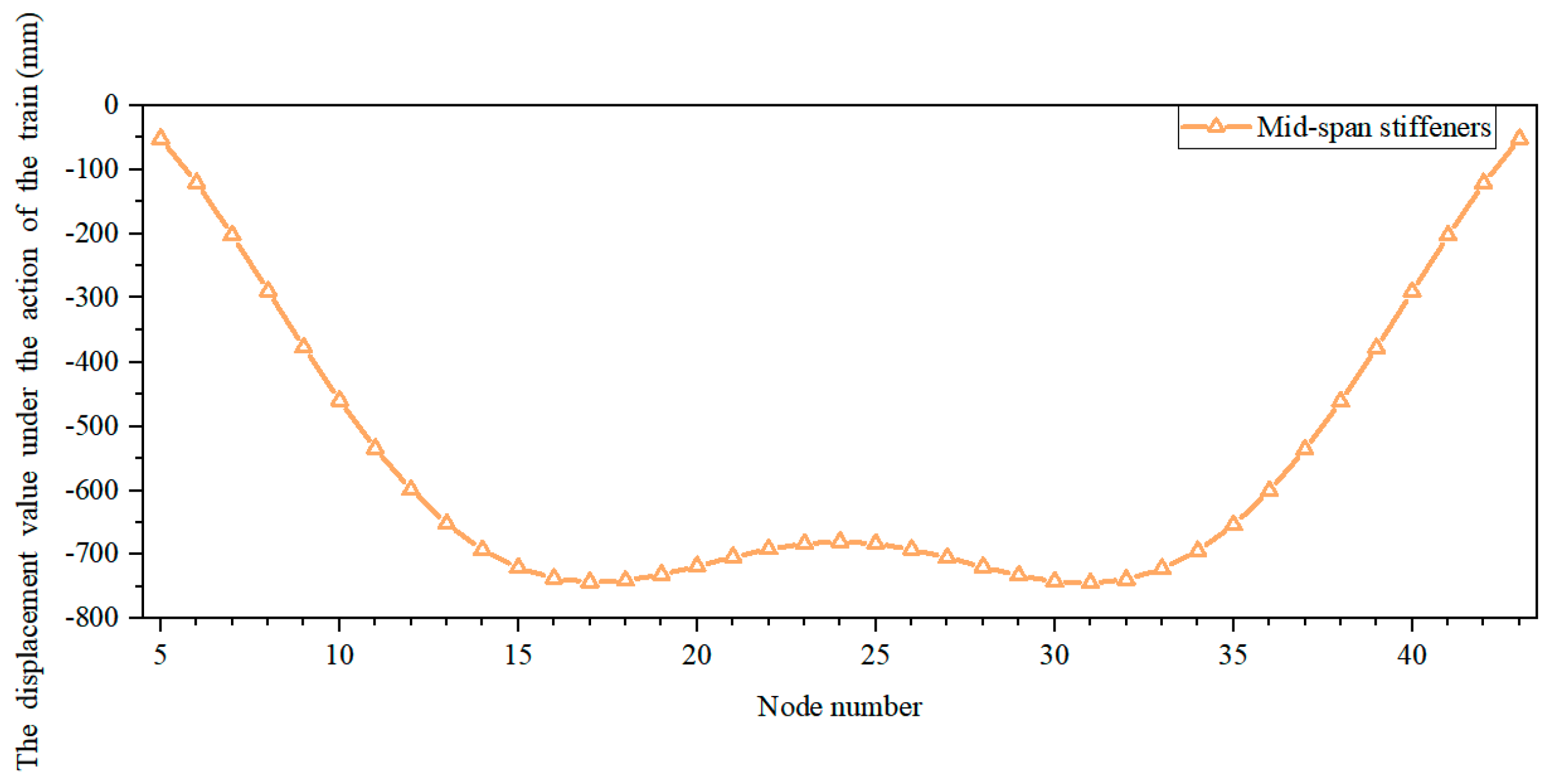
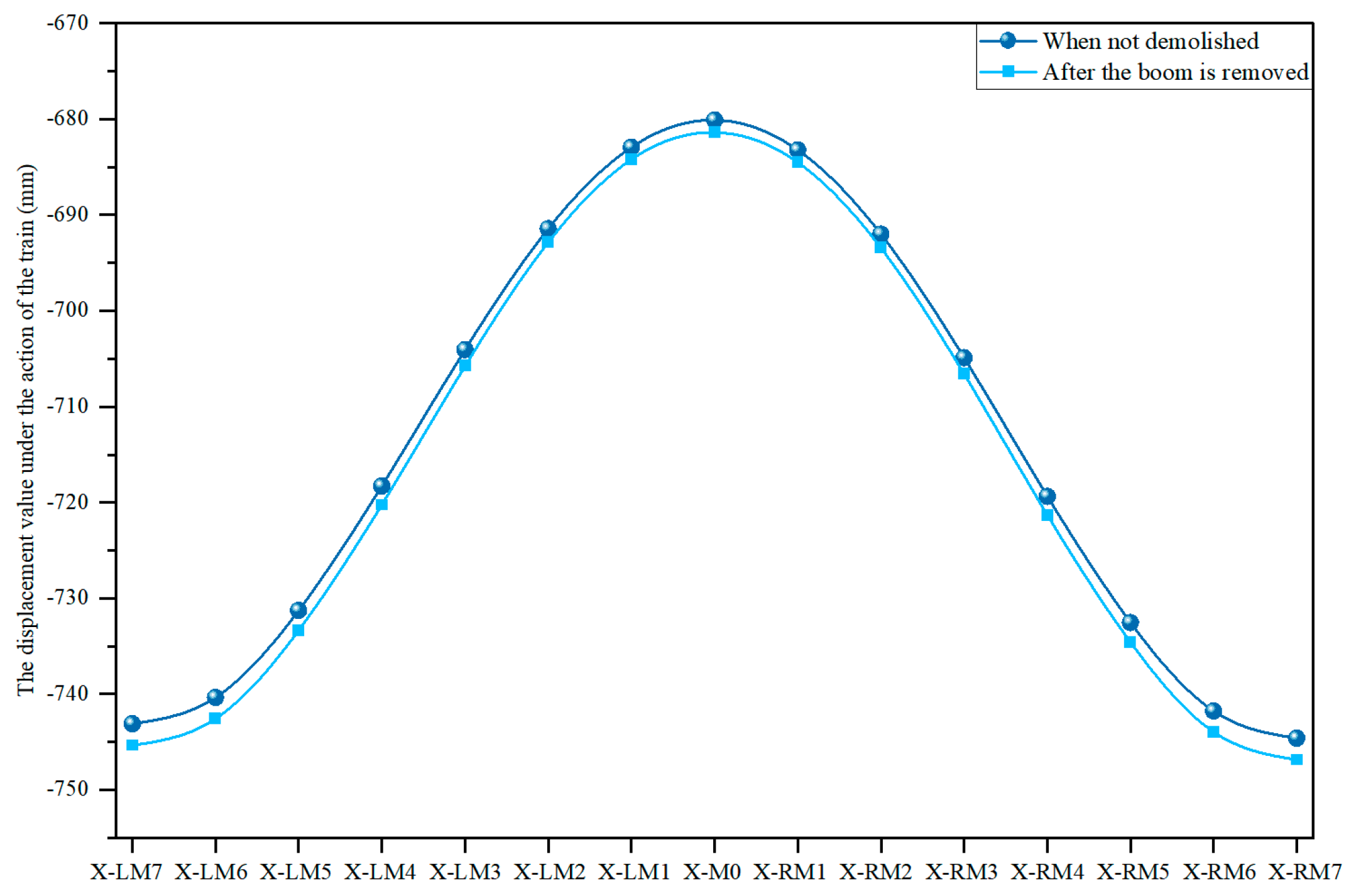
4.2.3. Analysis of Vertical Deformation of the Stiffened Beam

In order to accurately analyze the interface of the most unfavorable load exerted by trains on the stiffened beams of completed bridges, this study adopted a simulation scheme in which fully loaded trains were placed on the middle span, as shown in Figure 27. To further study the adverse deformation of the mid-span stiffened beam in the absence of the suspender, we removed the joint suspender of the most unfavorable load surface, as shown in Figure 28.
As can be seen from Figure 27, under the action of fully loaded trains, the most unfavorable load interface of the railway suspension bridge is precisely located at the specific nodes of the 1/4 and 3/4 beam systems, and the observed maximum displacements reach −743.11 mm and −744.63 mm, respectively.
As can be seen from Figure 28, when the train is running and the suspender node changes (compared with the unremoved state), the displacement change of −2.25 mm is generated. According to the relevant provisions of the code [14] for the maximum vertical deformation of the beam body of the suspension bridge under the action of the train, the warning value is set as L/600, and the safety value is set as L/450 (L is the bridge length). According to the calculation, when the deformation of the beam joint of the suspension bridge reaches −1000 mm under the action of the train, the early warning mechanism will be triggered, and the safety lower limit is −1333.3 mm. In the two most unfavorable load sections involved in the current study, the maximum displacement is only −745.35 mm~−746.88 mm, which is far lower than the warning value and the safety lower limit. The feasibility of the unbraced replacement method in the replacement of the suspender of the rail suspension bridge is proved. Since the deformation of the stiffening beam is always within the safe and controllable range and does not reach the warning limit in the process of suspender replacement, it can be seen that the adoption of an unsupported replacement method can achieve the goal of suspender replacement without interrupting traffic based on effectively guaranteeing the safety of the structure.

4.3. Safety Control Index Analysis

Based on the above analysis, through theoretical calculation and data processing, the relevant control index limits that can ensure the safety and stability of the structure and meet the requirements of normal operation performance are proposed, as shown in Table 8.
As can be seen from Table 8, for working conditions 1~15, the structural response is theoretically analyzed under static load and full train load, respectively, and the safety index proposed above is substituted for calculation. The results show that under static load, the safety coefficient of adjacent cable forces is higher than 2.0, the deformation difference of the main cable is less than 10 mm, and the deformation of the stiffened beam must meet the limit requirements specified in the table above in the real bridge experiment. Under full load conditions, all indices of main cable deformation, cable force, and stiffened beam deformation should also meet the requirements listed in the above table during the real bridge experiment.

4.4. Real Bridge Monitoring

Based on the above numerical simulation analysis, the unsupported replacement method is feasible. To further verify the effectiveness of the unsupported replacement method, this paper takes the Chongqing Egongyan Rail-transit Bridge as the object and conducts a real bridge test. During the test, the cable force changes of the adjacent suspender at the place where the suspender is replaced and after replacement as well as the deformation of the mid-span stiffening beam are monitored.
In this study, working condition 2 is selected for the real bridge experiment, and the cable force during the replacement of the LM7 suspender and the deformation data of beam system nodes at L/2 in the middle span during the replacement of the M0 suspender are collected by the structural deformation and cable force monitoring system. Among them, the removal time of LM6 is from 15:00 to 18:00 on 29 May 2023, and the removal time of M0 is from 16:24 to 16:25 on 13 June 2023. Therefore, cable force monitoring data of LM7, the adjacent suspender of LM6, from 15:00 to 18:00 on 29 May 2023, and stiffening beam deformation data of L/2 in the middle span of the bridge from 16:24 to 16:25 on 13 June 2023, were collected for analysis, as shown in Figure 29 and Figure 30. Meanwhile, to further verify the cable force and vertical deformation after replacement, the cable force monitoring data of LM7 from 15:00 to 18:00 on 30 May 2023, and the mid-span vertical deformation near M0 suspender from 16:24 to 16:25 on 14 June 2023, were selected, as shown in Figure 31 and Figure 32.
As can be seen from Figure 29, when the train is in operation and the LM6 suspender has been removed, the cable force of the adjacent LM7 suspender presents an uneven vibration change due to the significant influence of the key factor of vertical acceleration of the train. In this process, the maximum cable force peak value can reach 245 kN, which is far lower than the cable force limit of 456.34 kN in the safety control index compared with Table 6. As can be seen from Figure 30, after the removal of No. M0 boom, the vertical deformation characteristics in the span changed dramatically. In the specific period of 76~79 s, its deformation fluctuated greatly in the range of −37.4 mm to ~18.6 mm. At the same time, a significant displacement of −224.4 mm was also generated at the beam joint at L/2 in the middle span, but the deformation limit of the reinforced beam was also within −681.38 mm in the safety control index, which proves that the structural stress and deformation in the demolition process are in the safe category.
As can be seen from Figure 31, after the completion of the suspender replacement project, the bridge cable force and the vertical deformation of the main beam were accurately measured twice with the help of the structural deformation and cable force monitoring system. Monitoring data show that the cable force of LM7 shows a specific range of variation, between 75 kN and 176 kN, and shows a trend of steady balance. It is proved that the disturbance caused by the suspender replacement operation to the cable force system is evolving steadily towards a relatively stable state after the dynamic course of self-adjustment and stress redistribution within the structure, which effectively demonstrates the good adaptability and internal balance restoration efficiency of the structure.
As can be seen from Figure 32, the vertical non-uniform deformation that existed before the beam system joints at L/2 in the mid-span has been significantly alleviated. Among them, the maximum vertical deformation is −223.4 mm, while other parts do not show significant abrupt displacement, and the overall displacement fluctuates slightly around a reference line. It is proved that the replacement of the suspender effectively optimizes the deformation characteristics of the structure in this area, promotes the vertical deformation distribution of the beam system joints to be more uniform and reasonable, and thus significantly improves the overall stability and safety of the structure.
As a key force transfer component in the bridge structure system, the change of structural response of the suspender after its replacement reflects the complex process of mechanical balance reconstruction of the whole structure system after the change of local components. This reconstruction process not only covers the redeployment and optimization of cable force but also involves the re-distribution of internal stress of beam structure and the cooperative operation of the deformation coordination mechanism. Through continuous monitoring and in-depth analysis of these changes, potential structural safety risks can be detected in time, and corresponding preventive disposal and repair strategies can be carefully formulated accordingly to effectively ensure that the bridge always maintains a safe and reliable operation state during the long operation cycle.

5. Conclusions and Prospect

5.1. Conclusions

This research will not support replacement method is first used in rail suspension bridge, relying on Chongqing Egongyan Rail-transit Bridge 15 in the midspan cross rod (LM7~RM7) for suspender replacement without interrupting traffic conditions. Through the analysis of safety control indicators and Midas Civil numerical simulation, the following conclusions are drawn:
Demolition of single derrick results in adjacent derrick cable force growth of 42% to 55%, demonstrating demolition side effects. The main cable is warped 100.69–152.09 mm at the removed node, and the deformation of adjacent nodes shows regularity. The downstream removal causes the upstream main cable to warp, and the amplitude is not dominated by the height difference of the completed bridge. The displacement of the joints of the stiffened beam is −11.73–7.44 mm, and the displacement of the adjacent joints presents a spatial attenuation characteristic, and the deflection amplitude is not restricted by the height difference of the finished bridge.
After the removal of the boom, the cable force of the adjacent boom increases significantly, with a maximum increase of 150.0 kN (49% above the upper envelope value), but the material properties can be adapted. The stress of the boom during operation is about 55 MPa, and the stress of the adjacent boom after removal increases by 23.5–27 MPa, and the total stress is much lower than the design strength. The maximum deflection change of the most unfavorable load node of the main cable is 16.54 mm (increase of 2.22%), and the interface displacement of the stiffened beam is −743.11~−746.88 mm, which is far lower than the warning and safety lower limit.
Through the safety control index and the real bridge test, the unsupported replacement method is safe and feasible under the condition of non-interrupted traffic. After removing the boom, the peak cable force of LM7 is 245 kN, which is lower than the limit of 456.34 kN. The vertical displacement in the span is −224.4 mm, which is lower than the deformation limit of the stiffened beam −681.38 mm. After replacement, the cable force of LM7 is stable in the range of 75–176 kN, and the joint deformation of the mid-span beam system is significantly eased (maximum −223.4 mm), indicating that the stability of the structure is significantly improved after stress redistribution and self-adjustment, and the overall performance tends to be optimized.

5.2. Prospects

In this research, the unsupported replacement method is applied to the rail suspension bridge for the first time, and the real bridge experiment is carried out to study it to a certain extent, but there are still the following shortcomings:
The study mainly focused on the influence of single factors (such as static load and train load) on the bridge structure, without considering the combined effect of ambient temperature, wind, suspender corrosion fatigue damage, etc. In the future, the structural response analysis model under the coupling of multiple factors will be built. An in-depth exploration of the relationship between different factors and their comprehensive impact mechanism on the suspender replacement process and the overall performance of the bridge provides a more comprehensive and reliable theoretical basis for the optimization of the suspender replacement plan, and further improves the safety and durability of the bridge in the long-term operation process.
To ensure the safety and comfort of driving, only the single-point replacement method is tested in this paper. Subsequently, algorithms can be introduced to carry out the analysis and optimization research of the multi-point replacement method.

Author Contributions

X.L. (Xiaogang Li): Conceptualization, validation, writing—review and editing, project administration. M.Z.: Investigation, writing—original draft, visualization. P.D.: Conceptualization, Methodology, software, validation. L.L.: Resources, data curation, formal analysis, writing—review and editing. X.H.: Investigation, resources, data curation. X.L. (Xiang Li): Conceptualization, validation, writing—review and editing. All authors have read and agreed to the published version of the manuscript.

Funding

This work was supported by China First Highway Engineering Co. R&D project (2024-B-22) and Chongqing University of Science and Technology graduate innovation program YkJCX2320608.

Data Availability Statement

All of the data and models that were generated and used during the study are available from the corresponding author by request. The data are not publicly available due to privacy.

Conflicts of Interest

Author Peng Ding was employed by the company T.Y.Lin International Engineering Consulting (China) Co., Ltd. Author Xiang Li was employed by the company China First Highway Engineering Co., Ltd. The remaining authors declare that the research was conducted in the absence of any commercial or financial relationships that could be construed as a potential conflict of interest.

References

  1. Feng, D.; Mauch, C.; Summerville, S.; Fernandez, O. Suspender Replacement for a Signature Bridge. J. Bridge Eng. 2018, 23, 11. [Google Scholar] [CrossRef]
  2. Zou, L.; Hu, Y. Analysis of mechanical properties of space network suspension rod tied arch bridge by suspension rod fracture. J. Shijiazhuang Tiedao Univ. (Nat. Sci. Ed.) 2023, 36, 28–33+68. [Google Scholar] [CrossRef]
  3. Yuan, A.; Yang, T.; Xia, Y.; Qian, L.; Dong, L.; Jin, X. Replacement of the Fire-Damaged Long Suspenders of the Runyang Suspension Bridge. Struct. Eng. Int. 2022, 32, 484–490. [Google Scholar] [CrossRef]
  4. Zhao, L.; Yang, Z.; Tong, X.; Zhang, Y.; Nie, R. Experimental Study on Fatigue Characteristics and Life Prediction of Rotating Restricted Short Suspender in Suspension Bridge. Buildings 2025, 15, 254. [Google Scholar] [CrossRef]
  5. Wang, S.; Guo, W.; Cao, M.; Li, Y. Bridge-Train-Passenger Coupling Vibration and Riding Comfort Analysis of Urban Track Line. J. Vib. Meas. Diagn. 2023, 43, 584–592+625. [Google Scholar] [CrossRef]
  6. Zhou, Q.; Liu, L.; Gong, K.; Qin, J. Influence of fastener failure on vertical vibration responses of the high-speed train-ballastless track-bridge coupled system. J. Rail Way Sci. Eng. 2020, 17, 1337–1345. [Google Scholar] [CrossRef]
  7. Wang, X.; Xie, G.; Zhang, Y.; Liu, H.; Zhou, L.; Liu, W.; Gao, Y. The Application of a BiGRU Model with Transformer-Based Error Correction in Deformation Prediction for Bridge SHM. Buildings 2025, 15, 542. [Google Scholar] [CrossRef]
  8. Sun, Z.; Ning, S.; Shen, Y. Failure Investigation and Replacement Implementation of Short Suspenders in a Suspension Bridge. J. Bridge Eng. 2017, 22, 8. [Google Scholar] [CrossRef]
  9. Wang, J.H.; Wang, X.S.; Yang, C.L. Construction and monitoring of suspension replacement project for Shantou Bay Bridge. Highw. Automot. Appl. 2015, 6, 172–177. [Google Scholar]
  10. Li, Y. Research on Replacement Methods and Bearing Capacity of Suspender Cables of In-Service Suspension Bridges. Master’s Thesis, Chang’an University, Xi’an, China, 2021. [Google Scholar] [CrossRef]
  11. Radojevic, D.; Kirkwood, K.F.; Matson, D.D. A Tale of Two Bridges: Extending the Lifetimes of the Lions Gate and Angus L. Macdonald Suspension Bridges. Struct. Eng. Int. 2019, 29, 527–532. [Google Scholar] [CrossRef]
  12. Adanur, S.; Okur, E.K.; Altunisik, A.C.; Gunaydin, M.; Rahwan, B.R. Investigation of the structural behaviors of Bosphorus suspension bridge with vertical hangers replaced by inclined hangers. Alex. Eng. J. 2023, 65, 75–102. [Google Scholar] [CrossRef]
  13. Wang, T.; Wang, L.; Zhang, X.; Liu, D. Investigation on the dynamic responses of a road-rail suspension bridge and the trains on bridge in case of suspender fracture. J. Vib. Shock. 2023, 42, 273–282. [Google Scholar] [CrossRef]
  14. GB/T 39559.2-2020; Specifications for Operational Monitoring of Urban Rail Transit Facilities-Part 2. Bridge. National Standards of the People’s Republic of China: Beijing, China, 2020.
  15. JTG/T J21-2011; Specification for Inspection and Evaluation of Load-bearing Capacity of Highway Bridges. Ministry of Transport of the People’s Republic of China: Beijing, China, 2011.
  16. JTG/T D65-05-2015; Design Code for Highway Suspension Bridges. Ministry of Transport of the People’s Republic of China: Beijing, China, 2015.
  17. JT/T 449-2021; Suspender of Highway Suspension Bridge. Ministry of Transport of the People’s Republic of China: Beijing, China, 2021.
  18. GB/T 51234-2017; Code for Design of Urban Rail Transit Bridge. Ministry of Transport of the People’s Republic of China: Beijing, China, 2017.
  19. Wang, Z.; Wu, H.; Zhou, Z.; Wang, S. Analysis on near influence of cable force in large-span self-anchored suspension bridges. China Civ. Eng. J. 2016, 49, 51–60. [Google Scholar]
  20. Wang, Z.; Wu, H.; Zhou, Z.; Wang, S. Displacement characteristics analysis on the main cable of large-span self-anchored suspension bridge. China Civ. Eng. J. 2015, 48, 102–111. [Google Scholar] [CrossRef]
  21. Wu, H.; He, L.; Guo, H.; Wang, S.; Wang, Z. Analysis on the Displacement Characteristics of the Main Cable in the Transformation Process of Cable-suspension System of Self-anchored Suspension Bridge. Highw. Eng. 2021, 46, 33–38. [Google Scholar] [CrossRef]
  22. Xiang, Z.; Jiang, J.; Chen, G.; Zhang, Z. Practical calculation analysis of system transformation of self-anchored suspension bridge. J. Harbin Inst. Technol. 2021, 53, 164–169. [Google Scholar]
  23. Jiang, J.; Liu, X.; Chen, G. Suspension force loss analysis of self-anchored suspension bridge. J. China Foreign Highw. 2020, 40, 136–143. [Google Scholar] [CrossRef]
  24. T/CECS G-M61-01-2019; Technical Specifications for Road Concrete Bridge Demolition. China Association for Engineering Construction Standardization: Beijing, China, 2019.
  25. Zang, Y.; Dai, J.; Shao, C. Key Design Techniques for Egongyan Railway Transit Bridge. Bridge Constr. 2020, 50, 82–87. [Google Scholar]
  26. Shen, R.-L.; Bai, L.-H.; Zhang, S.-H. Ultimate capacity of narrow type steel box section for railway self-anchored suspension bridge under bias compression. Adv. Steel Constr. 2019, 15, 173–184. [Google Scholar] [CrossRef]
  27. Liu, A.; Li, X.; Guo, X.; Ding, P.; Qi, Y. Reasonable Stiffness Limits for Long-Span Track Suspension Bridge. J. Chongqing Jiaotong Univ. (Nat. Sci.) 2018, 37, 13–20. [Google Scholar]
  28. JTG D60-2015; General Specifications for Design of Highway Bridges and Culverts. Ministry of Transport of the People’s Republic of China: Beijing, China, 2015.
  29. Wang, T.; Zhang, X.; Wang, L. Dynamic Response of Cable-Stayed Bridge and Trains on Bridge Under Cable Breaking Conditions. J. Southwest Jiaotong Univ. 2024, 59, 627–636. [Google Scholar] [CrossRef]
  30. Yu, Z.; Zhi, L.; Lu, J.; Yu, X.; Beach, D. Broken cable-induced dynamic response of long-span concrete cable stayed bridge during construction. J. Vib. Shock. 2021, 40, 237–246. [Google Scholar] [CrossRef]
Figure 1. Simplified diagram of catenary segment model.
Buildings 15 01406 g001
Figure 2. Schematic diagram of missing catenary segment of the suspender.
Buildings 15 01406 g002
Figure 3. Track special bridge layout(unit: mm).
Buildings 15 01406 g003
Figure 4. Track special bridge sling number.
Buildings 15 01406 g004
Figure 5. Main beam profile (unit: mm).
Buildings 15 01406 g005
Figure 6. Pylon profile (unit: cm).
Buildings 15 01406 g006
Figure 7. Main cable profile.
Buildings 15 01406 g007
Figure 8. Suspender profile.
Buildings 15 01406 g008
Figure 9. Three kinds of short profiles of suspenders.
Buildings 15 01406 g009
Figure 10. Health monitoring system schematic.
Buildings 15 01406 g010
Figure 11. Finite element numerical analysis model.
Buildings 15 01406 g011
Figure 12. Steel box girder segment model.
Buildings 15 01406 g012
Figure 13. Main tower segment model.
Buildings 15 01406 g013
Figure 14. Main cable and sling segment model.
Buildings 15 01406 g014
Figure 15. Loading diagram of the 6-car train (unit: m).
Buildings 15 01406 g015
Figure 16. Schematic diagram of a single train model.
Buildings 15 01406 g016
Figure 17. Diagram of train crossing bridge (unit: mm).
Buildings 15 01406 g017
Figure 18. Displacement of the main cable under different working conditions (unit: mm).
Buildings 15 01406 g018
Figure 19. Displacement diagram of upstream main cable during Downstream replacement (unit: mm).
Buildings 15 01406 g019
Figure 20. Cable force variation in working conditions 1~15 (kN). Where: (a) indicates the change of cable force in working conditions 1~5; (b) indicates the change of cable force in working conditions 6~10; (c) indicates the change of cable force in working conditions 10~15.
Buildings 15 01406 g020
Figure 21. Effect comparison of cable forces (kN).
Buildings 15 01406 g021
Figure 22. Suspender removal Stiffened beam joint displacement (mm).
Buildings 15 01406 g022
Figure 23. Displacement diagram of upstream stiffened beam during downstream replacement (unit: mm).
Buildings 15 01406 g023
Figure 24. Downwarping diagram of the main cable with suspender removed and not removed (unit: mm).
Buildings 15 01406 g024
Figure 25. Cable force variation under train action (kN).
Buildings 15 01406 g025
Figure 26. Stress change diagram after removal of the suspender (MPa).
Buildings 15 01406 g026
Figure 27. Displacement diagram of maximum train load (mm).
Buildings 15 01406 g027
Figure 28. Displacement diagram of train beam system joints with a different suspender after removal (mm).
Buildings 15 01406 g028
Figure 29. When removing LM6, the cable force on LM7 under the action of the train.
Buildings 15 01406 g029
Figure 30. Displacement monitoring of beam system joints at 1 L/2 middle span.
Buildings 15 01406 g030
Figure 31. LM7 cable force after replacement.
Buildings 15 01406 g031
Figure 32. Displacement monitoring of beam system joints at mid-span L/2.
Buildings 15 01406 g032
Table 1. Monitoring equipment information table.
Monitoring ItemSerial NumberDevice TypeMonitoring Accuracy
Load monitoring(1)odometer0.1% F.S
Static and dynamic response
monitoring of the whole structure
(2)GNSS1/S
(3)Intelligent digital static level0.01 mm
Structure local response monitoring(4), (5)String type digital through the core
anchor cable meter
±1 kN
Table 2. Main component characteristic parameters.
Main Component
Characteristic
Parameters
MaterialsUnit Weight (kN/mm3)Elastic Modulus (kN/mm2)Poisson’s Ratio
Main cable1860 MPa high
strength steel wire
7.85 × 10−82000.3
Suspender1770 MPa high
strength steel wire
7.85 × 10−82000.3
Stiffening beamC55 Concrete2.5 × 10−835.50.2
Q4207.85 × 10−82060.31
Table 3. LS6 and RS6 boom cable force verification.
Boom LS6Boom RS6
Measured Days
(D)
Measured Value
(kN)
Theoretical Value
(kN)
Matching DegreeMeasured Value
(kN)
Theoretical Value
(kN)
Matching Degree
114515097%15616495%
214215095%15816496%
314615097%15616495%
414515097%15716496%
514215095%15816496%
614315095%15916497%
714415096%15616495%
Table 4. Cable force verification of LM7 and RM7 boom.
Boom LM6Boom RM6
Measured Days
(D)
Measured Value
(kN)
Theoretical Value
(kN)
Matching DegreeMeasured Value
(kN)
Theoretical Value
(kN)
Matching Degree
132834096%32433597%
232534096%32033596%
332334095%31833595%
433334098%32533597%
532734096%32333596%
632634096%33333599%
732434095%33033599%
Table 5. Working condition setting.
ItemCategoryItemCategoryItemCategory
Working
condition 1
Remove LM7 suspenderWorking
condition 6
Remove LM2 suspenderWorking
condition 11
Remove RM3 suspender
Working
condition 2
Remove LM6 suspenderWorking
condition 7
Remove LM1 suspenderWorking
condition 12
Remove RM4 suspender
Working
condition 3
Remove LM5 suspenderWorking
condition 8
Remove M0 suspenderWorking
condition 13
Remove RM5 suspender
Working
condition 4
Remove LM4 suspenderWorking
condition 9
Remove RM1 suspenderWorking
condition 14
Remove RM6 suspender
Working
condition 5
Remove LM3 suspenderWorking
condition 10
Remove RM2 suspenderWorking
condition 15
Remove RM7 suspender
Table 6. Displacement of adjacent nodes of the main cable after removal of Suspender (unit: mm).
Suspender NumberWorking ConditionEast (R) Side (mm)West (L) Side (mm)
X-LM7Working condition 13.05/
X-LM6Working condition 22.184.72
X-LM5Working condition 30.952.91
X-LM4Working condition 40.532.03
X-LM3Working condition 5−0.010.95
X-LM2Working condition 6−0.100.71
X-LM1Working condition 7−0.100.29
X-M0Working condition 8−0.08−0.08
X-RM1Working condition 90.28−0.11
X-RM2Working condition 100.71−0.11
X-RM3Working condition 110.96−0.01
X-RM4Working condition 122.050.54
X-RM5Working condition 132.910.98
X-RM6Working condition 144.722.27
X-RM7Working condition 15/3.07
Table 7. Finite element numerical analysis model.
Suspender NumberWorking ConditionEast (R) Side (mm)West (L) Side (mm)
X-LM7Working condition 1−8.17/
X-LM6Working condition 2−7.95−8.14
X-LM5Working condition 3−7.48−7.68
X-LM4Working condition 4−7.15−7.38
X-LM3Working condition 5−6.37−6.53
X-LM2Working condition 6−5.36−5.54
X-LM1Working condition 7−4.65−4.70
X-M0Working condition 8−4.90−4.91
X-RM1Working condition 9−7.42−4.72
X-RM2Working condition 10−5.55−5.38
X-RM3Working condition 11−6.55−6.39
X-RM4Working condition 12−7.40−7.17
X-RM5Working condition 13−7.53−7.34
X-RM6Working condition 14−8.06−7.87
X-RM7Working condition 15/−8.28
Table 8. Safety control index.
Working ConditionStatic LoadStructural Response Under Full Load
Safety Factor (KS)Average Difference of Main Cable Deformation (mm)Deformation Limit of Stiffened Beam (mm)Cable Force Limit (kN)Main Cable Deformation Limit (mm)Deformation Limit of Stiffened Beam (mm)
Working condition 12.67−8.01−11.58460.78−16.42−745.35
Working condition 22.61−9.56−11.41456.34−16.54−742.58
Working condition 32.66−8.62−10.87457.96−16.32−733.35
Working condition 42.58−7.72−10.52451.35−16.50−720.24
Working condition 52.77−6.21−9.49441.05−16.05−705.76
Working condition 62.97−5.19−8.17424.52−15.59−692.87
Working condition 73.16−4.31−7.12415.81−15.16−684.20
Working condition 83.32−4.34−7.44411.36−15.39−681.38
Working condition 93.15−4.36−7.23416.58−15.22−684.51
Working condition 102.95−5.20−8.20425.50−15.61−693.45
Working condition 112.67−6.23−9.51441.62−16.06−706.6
Working condition 122.59−7.74−10.54451.01−16.52−721.32
Working condition 132.69−8.51−10.68457.20−16.26−734.60
Working condition 142.63−9.59−11.30456.02−16.51−743.98
Working condition 152.68−9.32−11.73460.77−16.47−746.88
Disclaimer/Publisher’s Note: The statements, opinions and data contained in all publications are solely those of the individual author(s) and contributor(s) and not of MDPI and/or the editor(s). MDPI and/or the editor(s) disclaim responsibility for any injury to people or property resulting from any ideas, methods, instructions or products referred to in the content.

