Article

Analysis of Deformation of Deep and Large Foundation Pit Support Structure and Impact on Neighbouring Buildings in Complex Environments

1
School of Water Conservancy and Transportation, Zhengzhou University, Zhengzhou 450001, China
2
School of Transportation Science and Engineering, Harbin Institute of Technology, Harbin 150000, China
3
School of Civil Engineering, Sun Yat-sen University & Southern Marine Science and Engineering Guangdong Laboratory (Zhuhai), Zhuhai 519082, China
4
State Key Laboratory for Tunnel Engineering, Sun Yat-sen University, Guangzhou 510275, China
5
School of Infrastructure Engineering, Dalian University of Technology, Dalian 116024, China
*
Authors to whom correspondence should be addressed.
Buildings 2025, 15(9), 1435; https://doi.org/10.3390/buildings15091435
Submission received: 23 March 2025 / Revised: 14 April 2025 / Accepted: 18 April 2025 / Published: 24 April 2025
(This article belongs to the Section Building Structures)

Abstract

:
The development trend of urban underground space towards deep and large three-dimensional foundation pit projects in complex environments faces the challenges of deformation and instability of supporting structures, strong sensitivity of the surrounding environment, and significant limitations of the traditional design theory. Based on the ultra-long/deep foundation pit project at the Shenzhen Airport East Station, a refined three-dimensional finite element simulation is used to systematically study the deformation mechanism of the supporting structures of deep and large foundation pits under a complex environment and investigate the influence on the neighbouring buildings. In this study, a three-dimensional finite element model is constructed considering the soil–structure coupling effect, and the mechanical response law of the foundation pit under the compliant–inverse combination method is revealed. Based on ABAQUS 6.14, a 10 m wide strip-shaped model of the central island area and an environmental risk source model including an underground station and group pile foundation are established. The analysis shows the following: the lateral shift in the ground wall is distributed in a ‘convex belly’ shape, with a maximum displacement of 29.98 mm; the pit bottom is raised in the shape of the bottom of a rebutted pot, and the settlement behind the wall has an effect ranging up to 3.8 times the depth of the excavation; the lateral shift in the side wall of the neighbouring underground station and the differential settlement of the group piles validate the predictive ability of the model on the complex-environment coupling effect. The research results can provide guidance for the design and construction of support structure projects and similar projects.

1. Introduction

With the growing importance of construction in the development and utilisation of aboveground and underground space, deep and large foundation pit engineering is becoming increasingly important. In the foundation pit engineering and construction process, the spatio-temporal effect is significant, and construction safety is especially critical [1,2,3,4,5]. As foundation pit excavation depths increase, the unloading state of the foundation pit soil body is constantly changing, which brings great challenges to the design of foundation pit supporting structures [6,7]. At present, the trend in urban underground space development is deep and large three-dimensional construction projects, including underground comprehensive traffic hub projects integrating aviation, high-speed railways, rail transit, long-distance passenger transport, city buses, and other modes of interchange [8,9]. However, the construction of deep and large pits in complex environments faces multiple challenges. The geological conditions are complex and changeable, leaving supporting structures prone to deformation and instability. The surrounding environment is sensitive, and the requirements for deformation control are extremely high. The traditional support design theory may not accurately reflect the interaction between the finite-width soil body and the adjacent pit excavation [10,11]. The deep and large pit project construction cycle is extensive, and the interaction relationship between pits is intricate and complex, facing problems such as a significant coupling effect, complex construction environment, interlocking work processes, and difficult time and space coordination [12,13].
At present, the theoretical research and measured data on the deformation of deep and large pit support structures and the mutual influence problem of adjacent pit excavation in complex environments are lacking, and the available means of analysis are limited and intricate [14,15,16,17,18]. Reasonable engineering measures must be taken to mitigate the mutual influence problem of adjacent pit excavation and to reduce the safety hazards [19,20]. In addition, the soil pressure distribution pattern and resistance coefficient of foundation soil differ from those of conventional foundation pits, and the spatial effect also affects the deformation of foundation pits and internal force of the enclosure structure. The theory of ultra-deep foundation pit design thus needs urgent improvement [21,22]. It is therefore vital to ascertain how to reduce the influence of cross construction spatio-temporal effects, solve the problem of coordinated forces in the support system, accelerate the construction progress, meet the target schedule, reduce project costs, and properly solve the problems of surrounding environmental protection, while the mutual influence between neighbouring parcels is key to ensuring the safety and economics of deep and large foundation pit projects [23,24,25]. This study aimed to deeply analyse the deformation characteristics of deep and large foundation pit support structures in complex environments, and proposed effective design methods.
Analysing the literature on internal force and deformation properties of foundation pits and surrounding structures, newer foundation pit zoning and foundation pit construction methods in soft soil layers along the coast of China have gradually replaced conventional foundation pit construction methods of managing the impact of large-scale deep foundation pit construction in dense urban areas on the surrounding environment. Shi et al. [26] analysed the traits of a triangular large-scale deep foundation pit in a soft-soil area in Shanghai and the impact of its excavation on the existing adjacent metro station. To reduce the impact of the large-scale unloading of the foundation pit on the station and tunnel structures, the entire foundation pit was divided into 18 areas of different sizes using a zoning-based construction method, which ensured the safety of the metro station structures and the surrounding infrastructure. Tan et al. [27] studied the deformation characteristics of large-scale deep foundation pits and the response in the hard-clay strata of the adjacent metro station structures. To reduce the deformation of the neighbouring underground structures caused by the foundation pit excavation, the project adopted the zoned excavation construction method, and used bored piles as partition walls to divide the whole foundation pit into three zones. Chen et al. [28] reported and studied the measured data relating to the construction of large-scale foundation pits in the dense urban area of Shanghai adjacent to Metro Line 9. To reduce the impact on the neighbouring underground structures, existing buildings, and facilities, the smooth zoning construction method was adopted to divide the whole pit into two small pits and one large pit immediately adjacent to the protection object, and the maximum horizontal deformation of the large and small pit enclosure structures was better controlled. Zeng et al. [29] studied the interaction between two adjacent square pits in Shanghai Expo Park, and by analysing the measured data they found that the synchronous excavation of the two adjacent pits with a spacing of 20 m exacerbated the horizontal deformation of the enclosure structure in the outer area of the pit, and the ground wall deformation in the middle area of the two pits was significantly smaller than that in the outer area. From the above literature review, it can be understood that the urban environment is becoming more and more complicated due to large-scale integrated underground space development oriented to the needs of the urban population. In the literature, only a small number of foreign scholars have explored the problem of interaction between surrounding structures due to deep and large foundation pit excavation, identifying an obvious nonlinear growth phenomenon causing the deformation of the surrounding environment during the construction of post-excavation foundation pits; however, in general, relevant research remains rare [30,31,32,33]. Domestic research on deep and large pits in complex environments mainly focuses on methods based on measured data and finite element calculations, finding that the impact of pit excavation on the adjacent surrounding environment is greater than the linear superposition of the impact of the excavation of individual pits, and the distribution of the pit form and excavation sequence has a significant impact on the superposition effect [34,35,36]. Overall, there remains a lack of systematic research on the interaction mechanism between deep and large foundation pits and surrounding structures in complex environments.
This study focuses on the key technical problems of deep and large foundation pit support engineering for a complex environment comprehensive transport hub, and investigates the interaction mechanism of a deep and large foundation pit and surrounding structures in a complex environment. A refined three-dimensional finite element model is constructed, and a numerical simulation is performed for the whole process of the ultra-long/deep foundation pit construction. The study verifies the applicability of the plane strain assumption in the middle of the super-long foundation pit, and reveals the dynamic coupling response mechanism between the supporting structure and the soil body. At the same time, this study constructs a three-dimensional finite element model containing the surrounding underground station and group pile foundation, and systematically analyses the influence law of foundation pit excavation on the neighbouring buildings.

2. Engineering Background

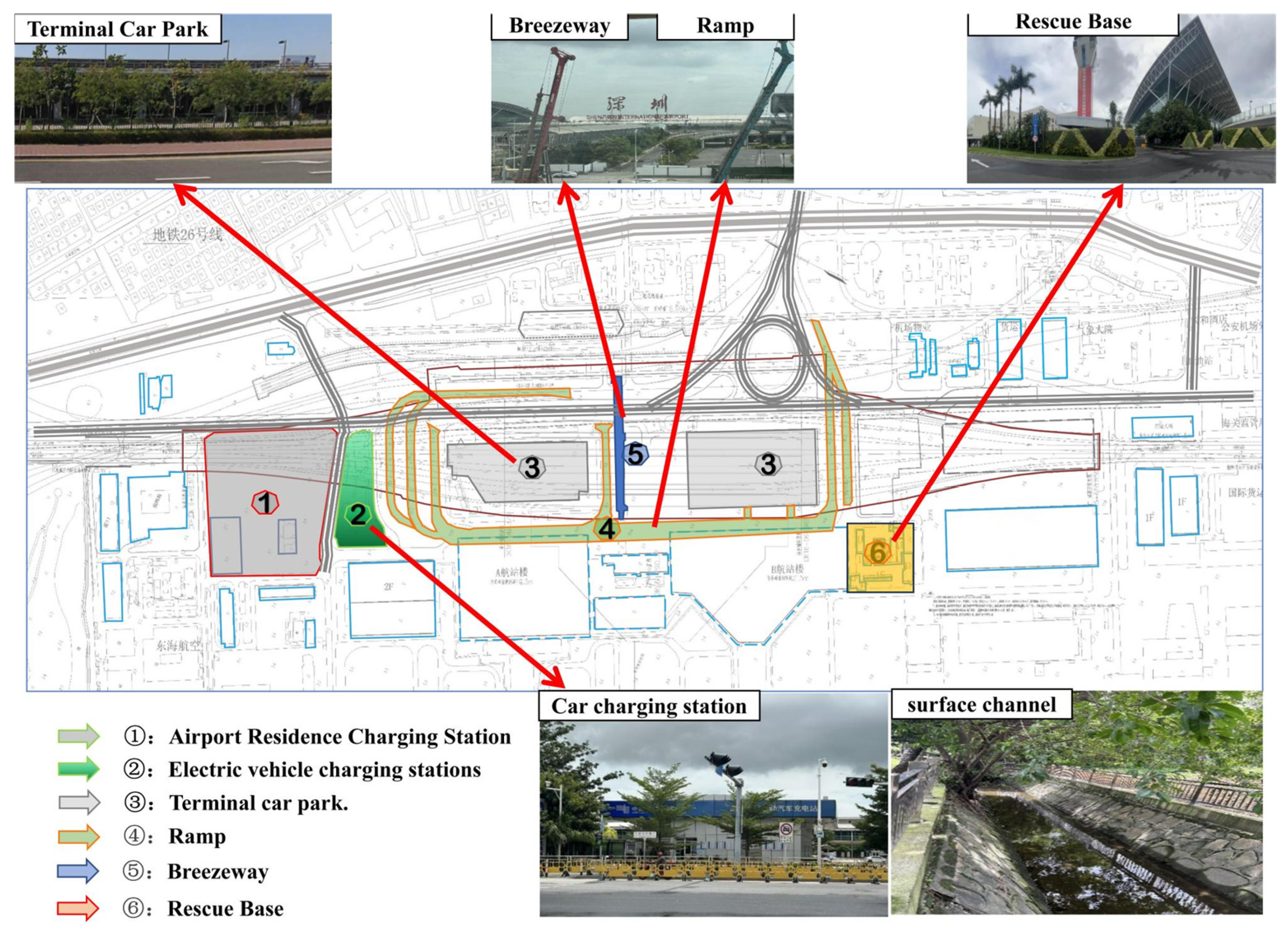
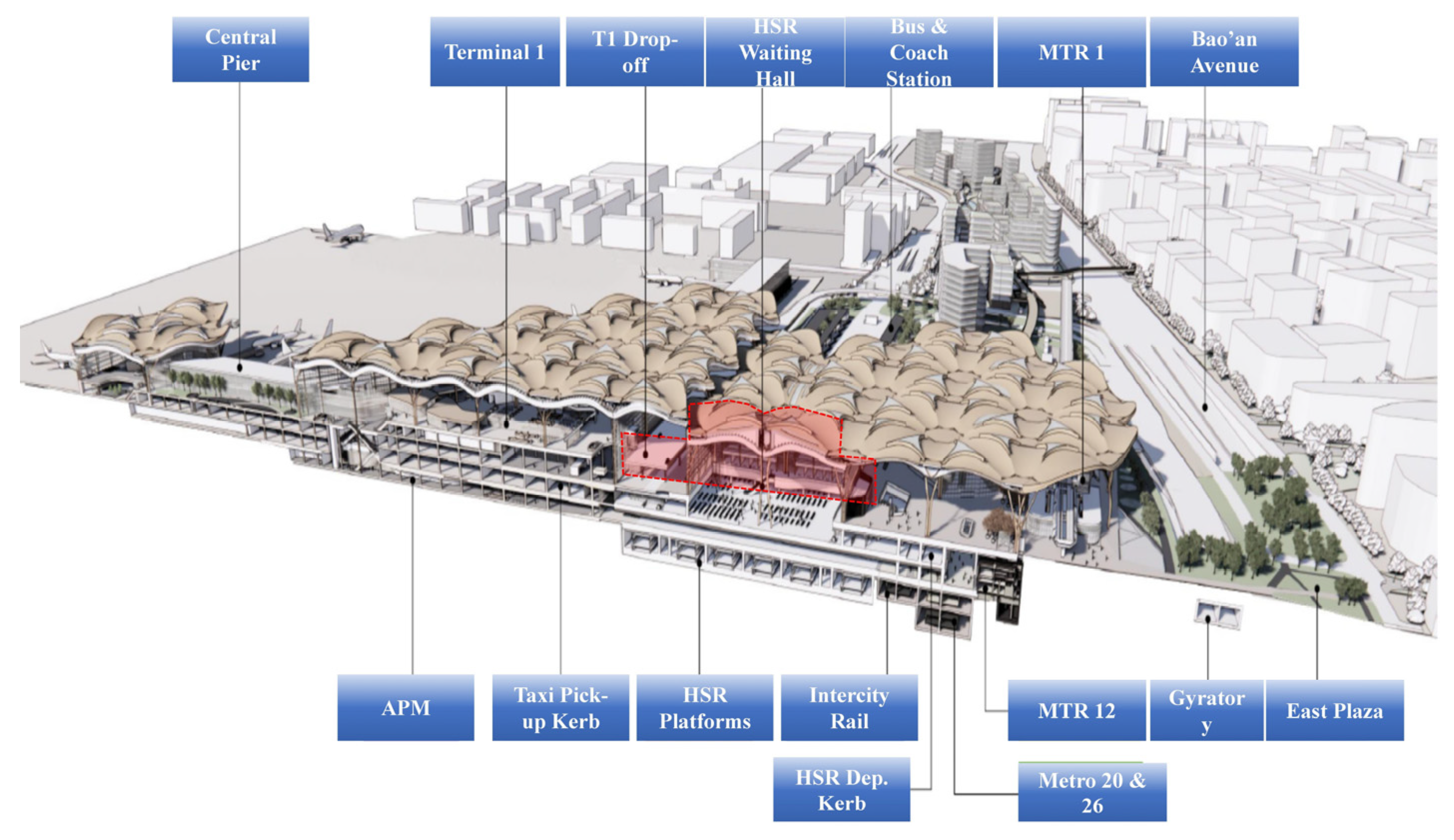
2.1. Environment and Surrounding Buildings

The surrounding environment of the Shenzhen Airport East Station pit project is complex, with many terminal buildings, in-service subways, and other structures, as shown in Figure 1 and Figure 2. The pit of the Shenzhen Airport East Station is about 1374 metres long, with an average depth of about 25 metres. The upper part is mainly silty clay and pulverised clay, with a thickness of 10–13 m, and the lower part is a rock layer. The proposed site is a sedimentary plain where the sea and land intersect, and the surface water system is relatively undeveloped. The surface water is mainly seawater, with a tidal range of 1–1.5 m. According to the classification of groundwater storage conditions, the site is mainly distributed with an upper layer of stagnant water and pore pressure water. The water content and permeability of the aquifer are uneven and discontinuous, with no uniform free-water surface, and the depth of the groundwater is 2.5–4.6 m. The water content and permeability of the aquifer is uneven and discontinuous. Figure 3 is a three-dimensional view of the pit

2.2. Enclosure Structure Form

As shown in Figure 4, Shenzhen Airport East Station is a three-storey station, and according to the station pit construction method, it is divided into three sections. The length of the pit in the middle of the station and part of the throat area is 773 m. The width of the pit is 98 m–159 m, the depth is about 25 m, and the ‘central island method’ of construction adopts an approach involving the intermediate multi-stage slopes of excavation plus both sides of the inverse construction approach, and the inverse approach is adopted using a 1.2 m high ground-connecting wall, the main structural floor, and a diagonal throwing brace. Enclosure form: The left-end head throat area pit length is 307 m, with a width of 57–98 m and a depth of about 25 m, and utilises the inverse construction method, using a 1.2 m high ground-connecting wall, main structure floor, and a multi-channel concrete support enclosure form. The right-end head throat area pit length is 294 m, with a width of 53–100 m, and a depth of about 25 m, and employs the reverse construction method, using a 1.2 m ground-connecting wall, main structure floor, and multi-channel concrete support enclosure form.
The central area is designed via a combination of the shun and reverse work methods, combining the central island and the reverse work method, as shown in Figure 5a and Figure 6a, and its construction steps are shown in Table 1.
Figure 5b and Figure 6b show the diagrams for both sides of the throat area of the reverse work area, and the corresponding construction steps are listed in Table 2.

3. Numerical Simulation

This study takes the Shenzhen Airport East Station super-narrow/long pit project as the research object (1374 m long and 53–159 m wide), selecting the 10 m wide core section in the middle of the pit as the research object and in line with engineering reality; in addition, the ABAQUS 6.14 software package is used to construct a finite element model of the composite work method in the downstream and inverse directions to simulate the deformation evolution law of the whole construction process in the central island area.
Since the length of the Shenzhen Airport East Station pit project is 1374 m (ultra-long) and the width is between 53 and 159 m (ultra-narrow), it can be simplified to a plane strain state for analysis under specific conditions. Firstly, the finite element model of the 10 m wide strip-shaped compliant and inverse combination method in the central island area is constructed, and the whole construction process in this area is simulated and analysed.

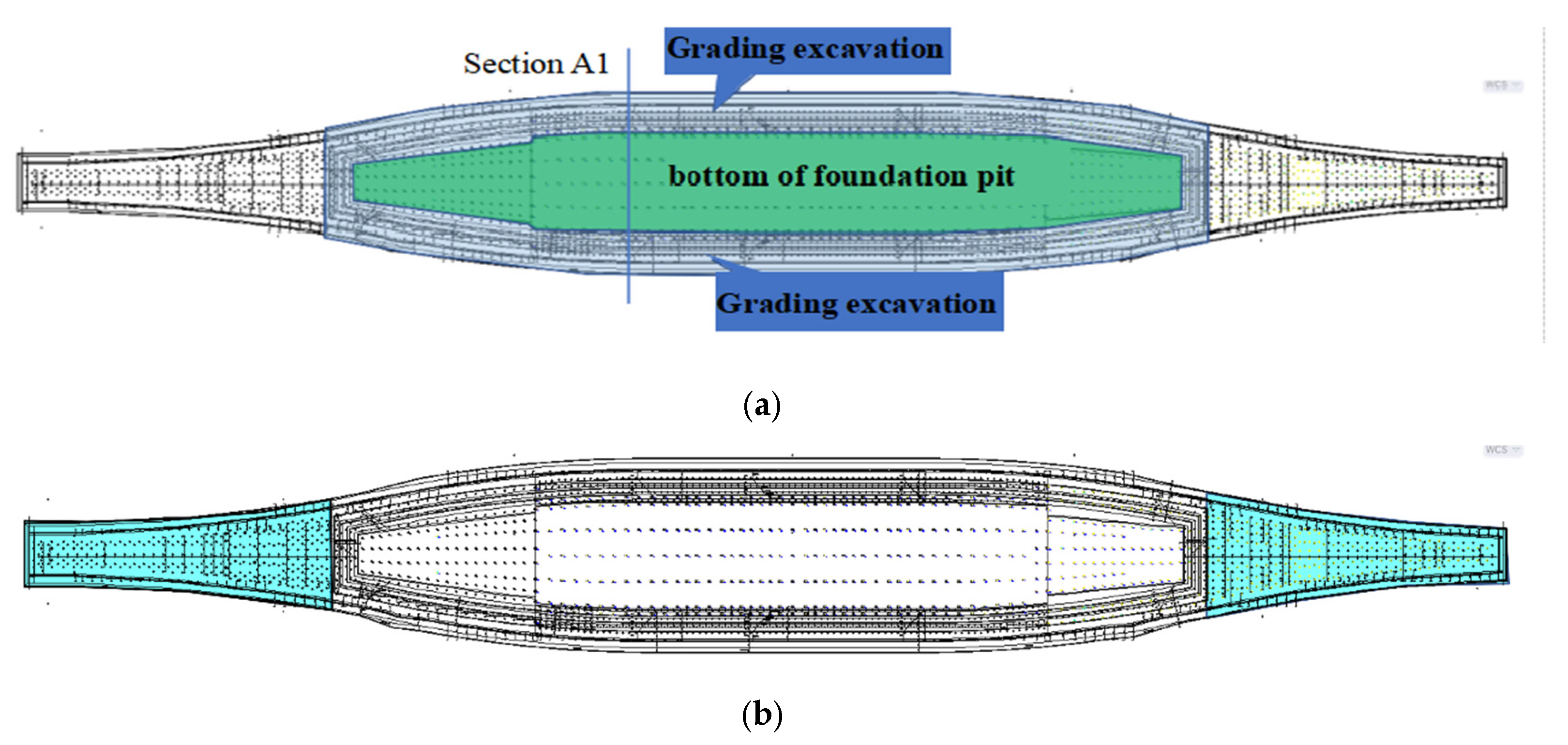
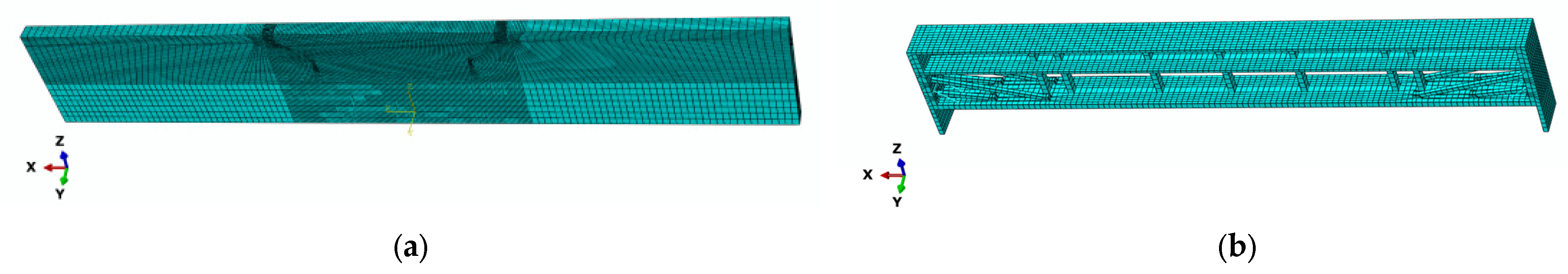
3.1. Modelling the Central Island Foundation Pit Excavation Process via the Composite Inverted Work Method

Due to the pit angle effect, the deformation of the pit within a certain range near the pit angle will generally be less than the deformation of the plane strain region of the pit. Finno et al. [37,38,39,40] have argued that the plane strain ratio (PSR; the ratio of the maximum lateral displacement in the middle of the pit to the results of the two-dimensional plane strain analysis) can be regarded as 1 when the pit length-to-depth ratio exceeds 6. Accordingly, the length-to-depth ratio of the pit project relied on in this study far exceeds that of an ordinary long pit, and the spatial effect of a complete pit does not usually need to be considered, and can be calculated according to the plane strain theory. In addition, the width of the ultra-narrow/long pit supported in this study decreases and the rigidity of the support system becomes larger when it is close to the throat area on both sides, and the corresponding pit deformation at the corner of the pit is smaller than that of an ordinary rectangular pit. In this study, the most representative 10 m thick dangerous section in the middle of the pit is therefore selected for the full finite element numerical simulation.

3.1.1. Model Assumptions

Bound connections are set up between ground-connected walls, side walls, floor slabs, concrete supports, and steel pipe replacement supports to simulate bolted or welded connections. The main structure floor slab does not undergo vertical deformation, and displacement restraints are set in the vertical direction. Assuming that the soil action, pit slope excavation, main structure floor construction, and other processes are completed instantaneously, the influence of soil rheology and time’s effect on the calculation model is not considered for the time being. Since the ground wall construction is driven into the bedrock, the excavation is performed before precipitation.

3.1.2. Analysis Step Setup

The actual construction adopts the central island combined method, whereby part of the floor slab and the structural base plate are also used as supporting structures, and utilises a combination of permanent and temporary construction. A step-by-step numerical simulation of the construction process allows us to more accurately reflect the deformation of the pit in the construction process. Using the ABAQUS software package’s ‘birth and death’ unit method, i.e., by changing the activation state of the unit to perform the simulation of the following construction process, the actual construction process is as shown in Figure 7, and the corresponding construction process and simulation analysis steps are shown in Table 3.

3.1.3. Contact and Boundary Conditions

In the excavation process simulation, the contact setup is mainly concerned with the part of the supporting structure that is in contact with the soil. The contact setup includes tangential and normal behaviour, where the normal behaviour is set as ‘hard’ contact and the tangential behaviour is set as penalised contact, with a friction coefficient of 0.35. Binding constraints are used to simulate bolted or welded connections for the side wall-to-floor wall, floor-to-side wall, and floor-to-column connections. Since the research object is the middle part of the excavated pit, symmetric constraints are set for the normal direction of the soil body, and symmetric constraints are set for the normal direction of the building part (including the side walls, diaphragm walls, floor slabs, and base slabs) to simulate the real construction conditions.

3.1.4. Properties of Materials

The soil body was modelled using the Mohr–Coulomb soil ontology model and was used as a strength criterion. The material properties of each layer are shown in Table 4, and the material parameters of the foundation support structure and main structure are shown in Table 5.

3.1.5. Modelling

For the excavation simulation of the foundation pit, this study performs three-dimensional finite element analysis. The 10 m part of the middle section of the excavated section is taken for the excavation simulation, the size of the soil model is 500 m × 10 m × 80 m, and the final size of the excavated section is 162.4 m × 10 m × 24.78 m. All the parts in the calculation process are divided into a total of 68,499 cell meshes, of which the soil and reinforced concrete parts use eight-node hexahedral cells (C3D8R). The steel support part uses two-node spatial linear beam cells (B31). The finite element model of the soil body and support structure is shown in Figure 8, where the x-direction indicates the long side of the soil body, the y-direction indicates the short side of the soil body, and the z-direction indicates the direction of gravity.

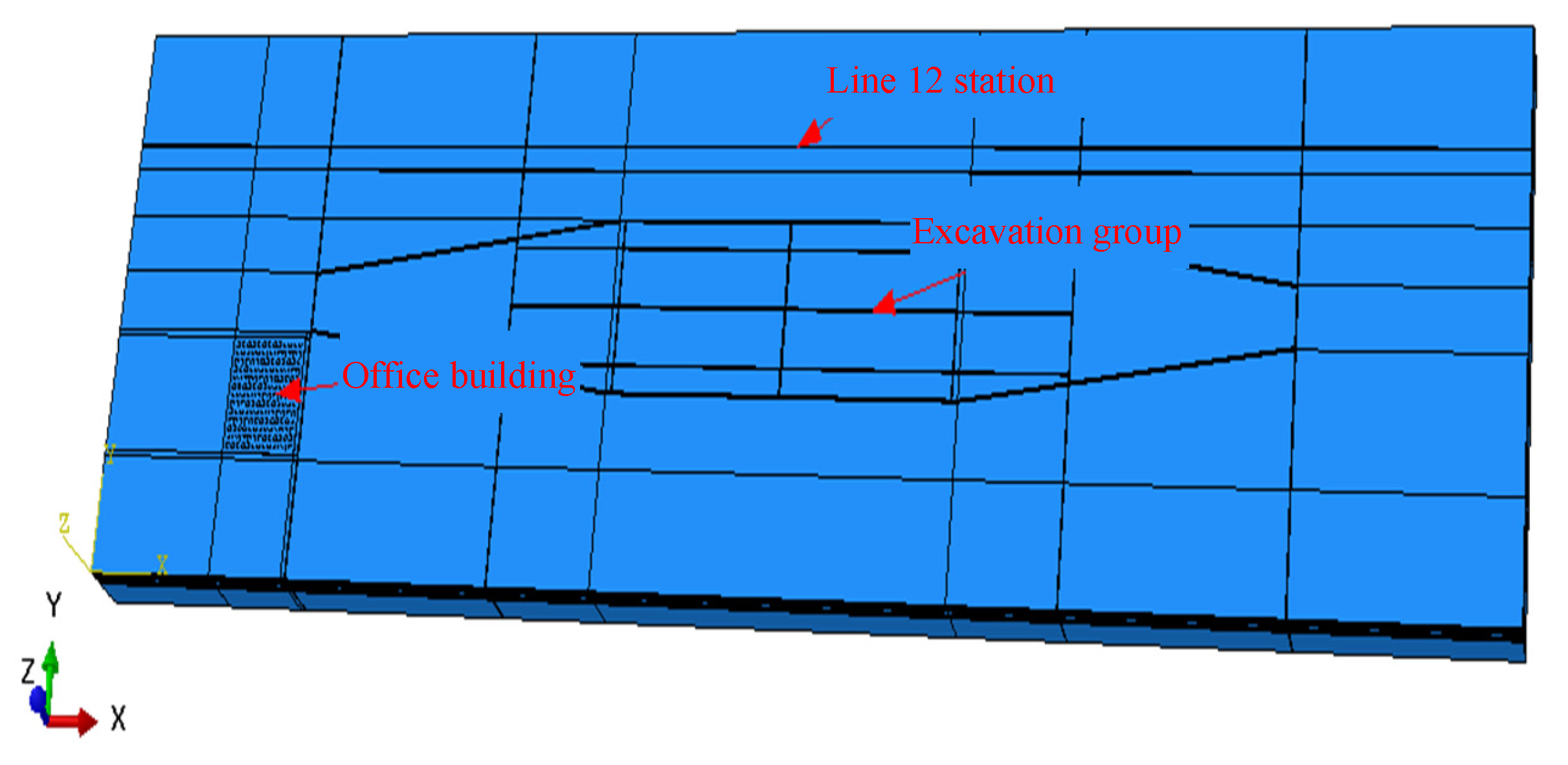
3.2. The Whole Process of Construction of Foundation Pit and Surrounding Structures
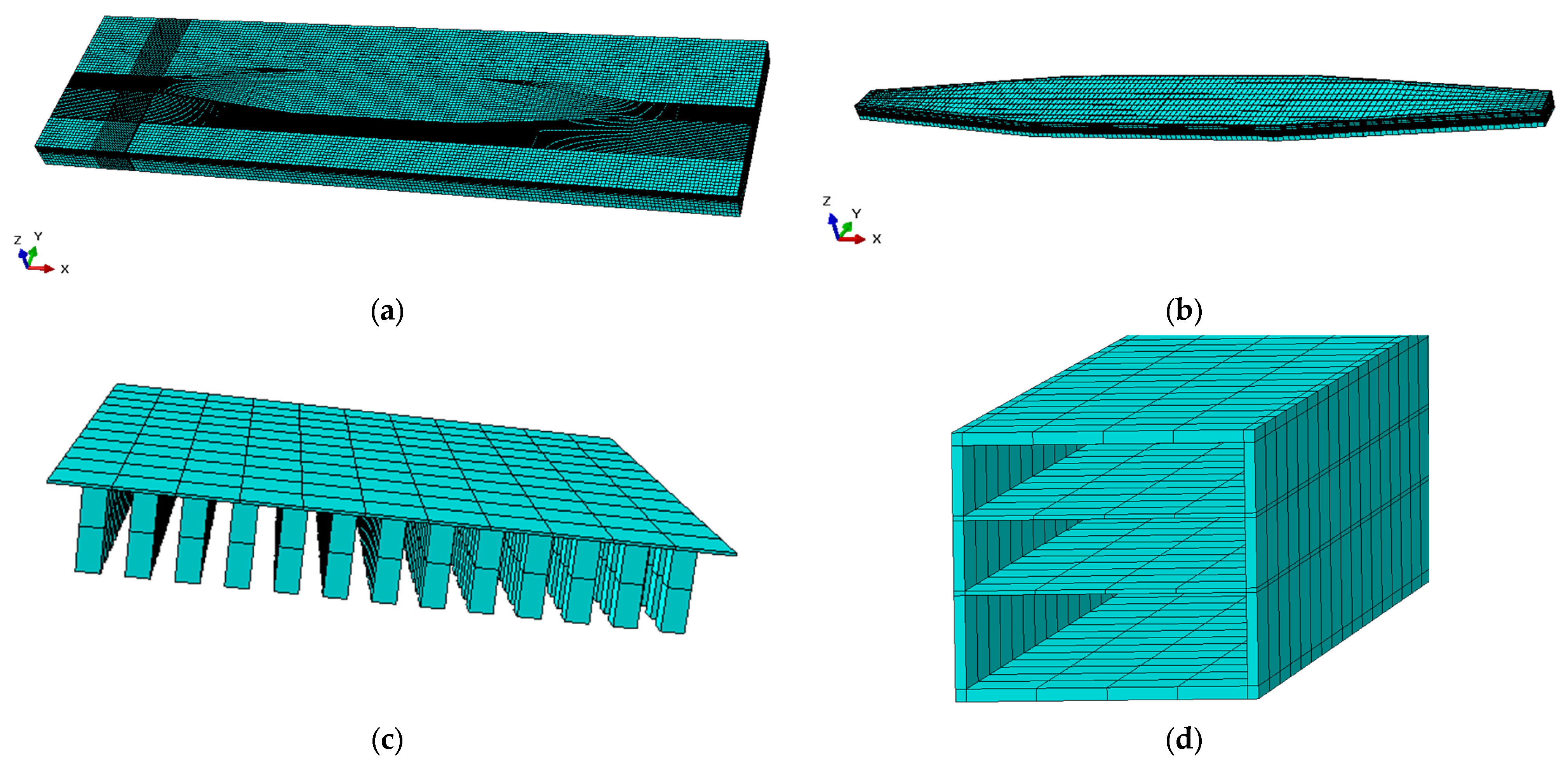
3.2.1. Modelling

Relying on the pit project of the airport station and the surrounding environment plan, representative surrounding structures are selected, including the administrative building of Donghai Airlines, which is a secondary environmental risk source, and the underground station of Line 12 in Yingying, which is a tertiary environmental risk source. Figure 9 illustrates the use of the ABAQUS commercial finite element software package to establish the three-dimensional construction process model, including the soil model and supporting structure model. The pile foundation model of the Donghai Airlines administrative building group and the underground station model are shown in Figure 9.
From Figure 10, the outer boundary of the soil body in the horizontal direction of the soil model is taken to the outer side of the foundation pit and the outer side of the peripheral structures by more than three times the maximum excavation depth, and the overall model size is 2000 m × 520 m × 80 m (length × width × height). As for the support structure model, it covers the support components such as ground-connecting wall, side wall, main structure floor slab, bottom slab, two-layer diagonal casting brace, two-layer concrete inner brace, and steel pipe guide brace, including the central island area and the throat area on both sides. Except for the two-layer diagonal throw braces and steel pipe replacement braces, which adopt B31 space beam units, the rest of the support components adopt C3D8 solid units. Following the division, a total of 517,932 units are included.

3.2.2. Calculation Assumptions and Soil Parameters

Bound connections are set up between ground-connected walls, side walls, floor slabs, concrete supports, and steel pipe replacement supports to simulate bolting or welding. The main structure floor slab does not undergo vertical deformation, vertical direction displacement constraints are set, and accordingly, engineering piles and lattice columns are no longer set. Assuming that the soil action, pit slope excavation, main structure floor construction, and other processes are completed instantaneously, the influence of soil rheology and time’s effect on the calculation model is not considered for the time being. As the ground wall construction is driven into the bedrock in the actual project, and the excavation is performed before the precipitation, the calculation model does not consider the effect of groundwater infiltration for the time being. The ideal elastic–plastic Mohr–Coulomb model (MC model) is chosen as the soil constitutive model, and the whole-site soil mechanical index parameters are obtained from the field test.

3.2.3. Contact Model and Boundary Conditions

In this study, the contact between the soil body and the supporting structure adopts face-to-face contact, and the normal compression is controlled by the ‘hard’ contact model; i.e., the normal pressure can be transferred only when the two objects are in the compression state, and the magnitude of the pressure transferred in the contact is not limited. The tangential friction is controlled by the ‘penalised’ contact model, which obeys Coulomb’s elastic–plastic friction law and is determined by the friction coefficient and the ultimate shear-sliding parameter. In this study, the ultimate shear-sliding parameter is 5 mm, the active side and side of the wall are in contact with the soil as a whole, and the passive side of the wall establishes the surface contact with the soil in each layer of excavation, respectively. The bottom of the wall and the soil are modelled as being in ‘tie’ contact, and the various parts of the supporting structure are also modelled as being in ‘tie’ contact; i.e., it is assumed that no relative sliding and deformation occurs in the bound area.
The finite element model is set with horizontal constraints in the x-direction, symmetric boundary conditions in the y-direction, and full constraints on the bottom surface of the model in the horizontal and vertical directions. Gravity acceleration is applied to the whole model to simulate the natural gravity, and a pressure of P = 88 KPa is applied to the surface of the bearing table of the group pile foundation to simulate the self-weight load of the upper floors.

3.2.4. Enclosure Parameters and Finite Element Simulation Implementation Steps

Since the model developed in this subsection is an overall 3D finite element model of the excavation process, it is necessary to account for material model parameters that do not appear, as shown in Table 6 below.
The specific implementation steps in the pit excavation simulation are shown in Table 7.

4. Results and Discussion

4.1. Numerical Simulation Results of Supporting Structure Deformation During Pit Excavation Process

Earlier, we established a finite element model for a 10 m wide central island area crossover combination by considering representative environmental risk sources, whereby both sides of the throat area covered the inverse excavation construction process for the whole three-dimensional refinement of the pit finite element model. We can thus perform a literature comparison to verify the correctness of the three-dimensional refinement results, and conduct a post-processing analysis to study the pit support structure of the internal forces, deformations, and evolution laws.

4.1.1. Validation of Numerical Model Calculations

Due to the lack of engineering monitoring data, the validation of the numerical simulation is judged using the trends in displacement and stress to verify the model’s correctness. In the middle, the unloading of the soil body produces a large displacement phenomenon, and shows a trend of having the largest displacement in the middle, which then decreases into the surrounding area, and at the edge of the pit, the displacement phenomenon is greatly reduced. At the same time, in the actual project where the underground station is located, a more obvious displacement was also produced. Figure 11 shows the lateral displacement of the ground wall in the central region of the pit in different analysis steps: through the activation of the ground wall in analysis step 2, and with the excavation of the pit, the counterpressure soil is removed step by step, the main structure is applied, the ‘cantilever-type’ lateral displacement of the ground wall gradually transforms into ‘convex belly’-type displacement, and the maximum lateral displacement is 29.4%. As shown in Equation (1), the maximum lateral movement is 29.98 mm, which also supports the correctness of the numerical model in this study.
δ = (qL4)/(8EI)[1 + (3k)/(4EIL3)]−1
where k is the soil bed coefficient and L is the cantilever length. Comparing the simulated value of 29.98 mm with the theoretical value of 31.2 mm, the deviation rate is 4.1%.

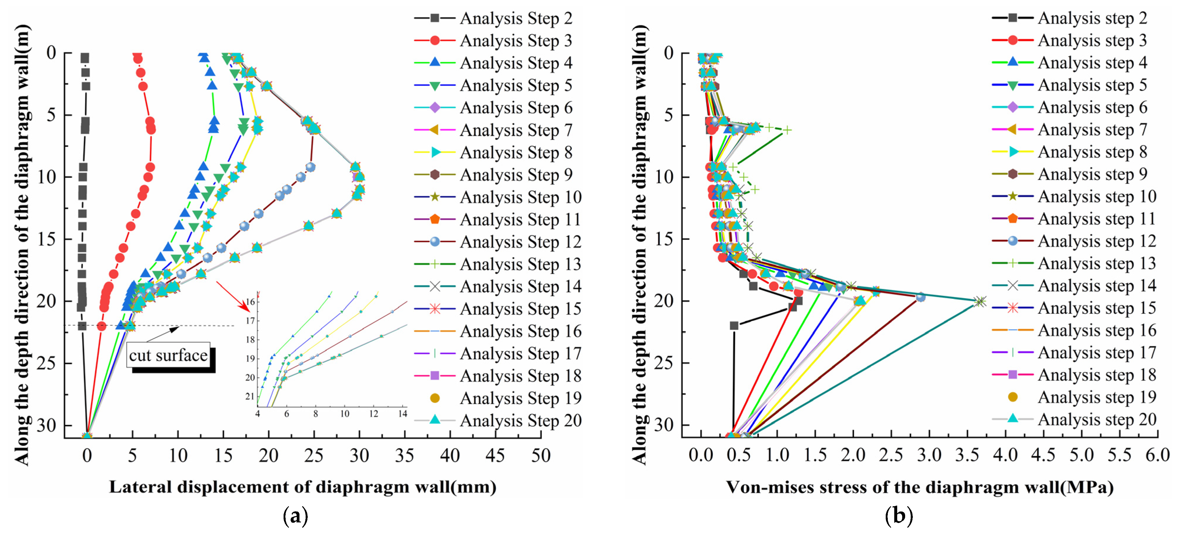
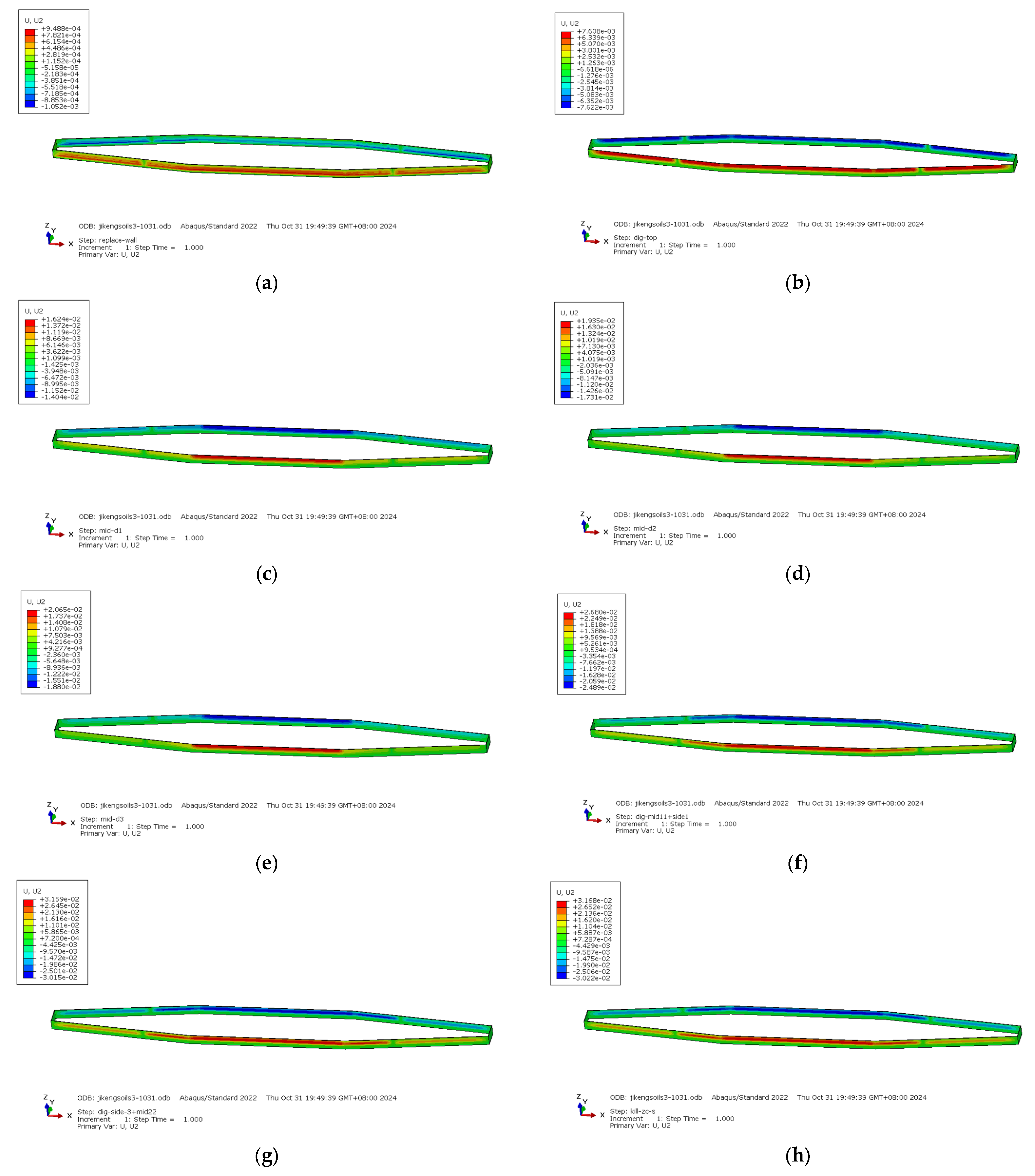
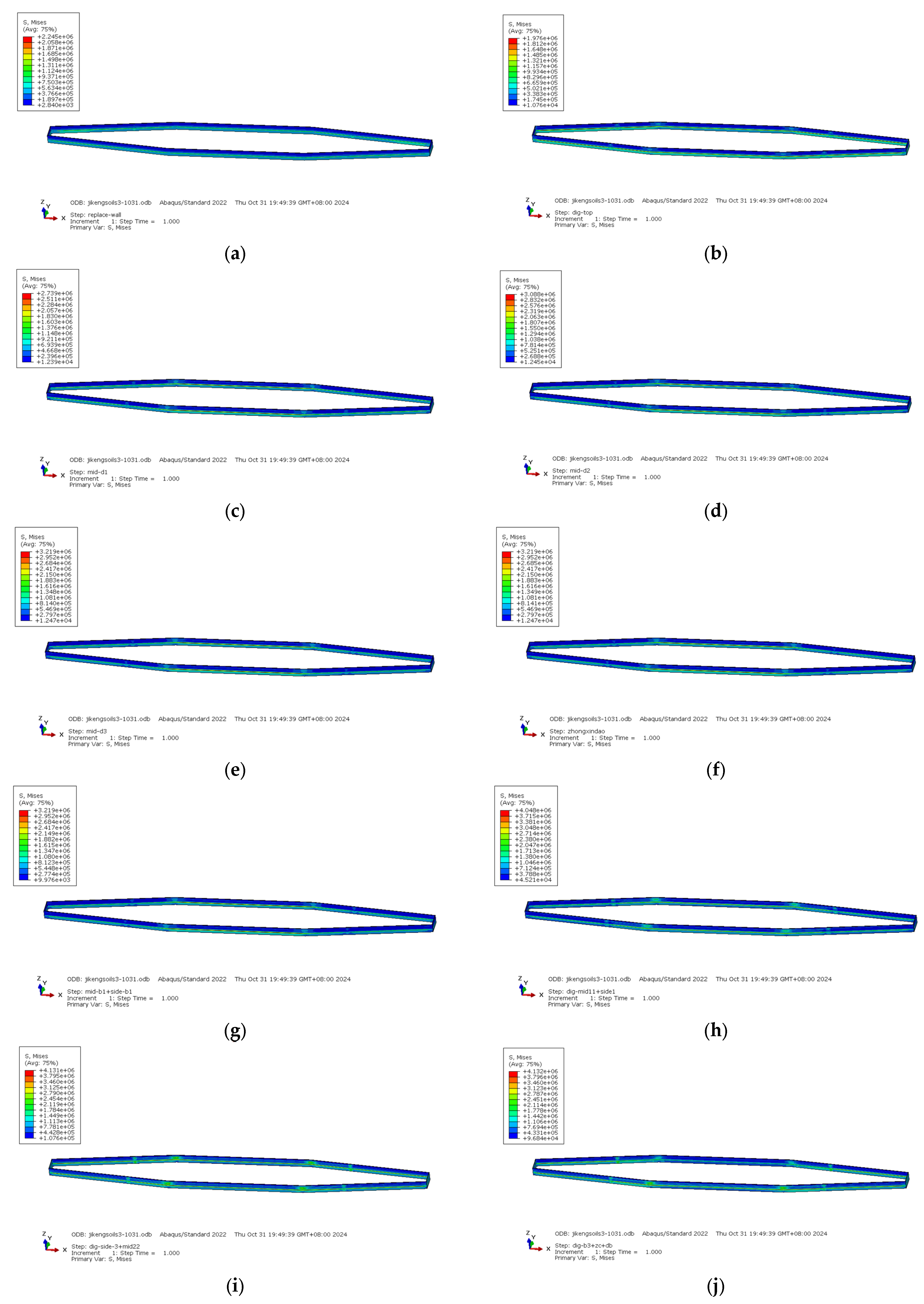
4.1.2. Deformation of Internal Forces in Foundation Pit Ground-Connected Walls

After verifying the accuracy of the 3D finite element numerical model, the foundation pit ground-connected wall was first analysed to establish the internal force deformation and its evolution law. The lateral displacement of the whole ground-connected wall can be seen in Figure 12a, and the von Mises stress cloud of the ground-connected wall after the completion of the foundation pit construction can be seen in Figure 12b. The horizontal displacement of the middle ground-connected wall is the largest. To intuitively show the lateral displacement changes in the ground-connected wall at different partitions, half of the model is taken along the direction of the ground-connected wall changes in Figure 12a, and the trend in the change along the path at a depth of 13 m from the top of the ground-connected wall is given in Figure 13. The maximum lateral displacement in the central part of the central island area is 27.23 mm, and when it extends to the two sides from the central part of the central island area, side displacement occurs in the pit’s shady corners due to the effect of the pit corners. There is a sudden large decrease to 18.96 mm, and then the side shift quickly rises to 25.63 mm, and finally the side shift decreases at the barrier wall in the throat area on both sides, which is due to the support effect provided by the barrier wall along the depth direction of the pit. In addition, the almost constant horizontal displacements in the central region of the central island area over an area of nearly 500 m also prove the correctness of the finite element model for the 10 m plane strain region presented above.
Figure 14a gives the lateral displacement of the ground wall in the middle of the pit along the depth direction of the ground wall and the von Mises stress in different analysis steps. It can be seen that in the second analysis step, the construction of the diaphragm wall was completed, and then in the third to sixth analysis steps, a vertical excavation and three sloping excavations were performed, and the side shift in the diaphragm wall exhibited a ‘cantilever type’ displacement, and the displacement in the middle and upper parts gradually increased until reaching the maximum side shift of 1.82 cm. There was no change in the side shift through the sixth to eighth analysis steps. At this stage, the first-floor slab in the central island area, the reverse zone in the central area, and the first-floor slab in the throat area on both sides were applied. In the ninth analysis step, the first layer of sloping backpressure soil removal was performed, the soil in both sides of the throat area was removed up to the second-floor slab, and there was a sudden change in the lateral movement of the pit in this stage, with the lateral movement increasing to 2.67 cm. In the subsequent analysis steps, 10–12, the second-floor slab in the central area of the backpressure area and both sides of the throat area was applied, the soil in both sides of the throat area was removed up to the third-floor slab, and the third-floor slab in both sides of the throat area was applied. Regarding the floor slabs, there was almost no change in the lateral movement of the ground-connected walls during these three analysis steps. The 13th analysis step removed the second layer of slope, released the backpressure soil, and removed the soil in the throat area on both sides to below the first layer of the concrete internal support; the lateral displacement of the ground-connected wall increased to the maximum lateral displacement during the whole construction process, which was 3.16 cm; and the subsequent construction operations, such as the removal of the internal support and diagonal throw brace, and the replacement of the brace with steel pipe in the 14–20th analysis steps, did not produce a significant change in the trend of the ground-connected wall’s lateral displacement. The von Mises stresses of the ground-connected wall along the depth direction of the ground-connected wall in the middle of the pit in different analysis steps are shown in Figure 14b. Unlike the ground-connected wall lateral shift, most of the changes in the ground-connected wall lateral shift occur in the upper part of the footing, while the maximum stresses in the ground-connected wall occur near the footing. The maximum von Mises stress of the ground-connected wall along the depth direction of the ground-connected wall in the central part of the pit is 3.7 MPa and reaches the maximum at the 14th analysis step, which is the stage of applying the third layer of the floor slab in the central region of the reverse-work area and applying the first layer of the concrete internal support in the throat region on both sides. In addition, the two peaks of the ground-connected wall occur approximately 6 m and 20 m from the top of the wall, respectively.
The overall lateral displacement and von Mises stress variation in the ground wall are listed below according to several more critical conditions given in Figure 15 and Figure 16. The maximum lateral movement of the ground wall is 3.168 cm, and the maximum von Mises stress is 4.132 MPa. The maximum lateral movement of the ground wall on both sides of the pit is different, with a difference of 1.4 mm, which is due to the presence of a metro station on one side of the pit.

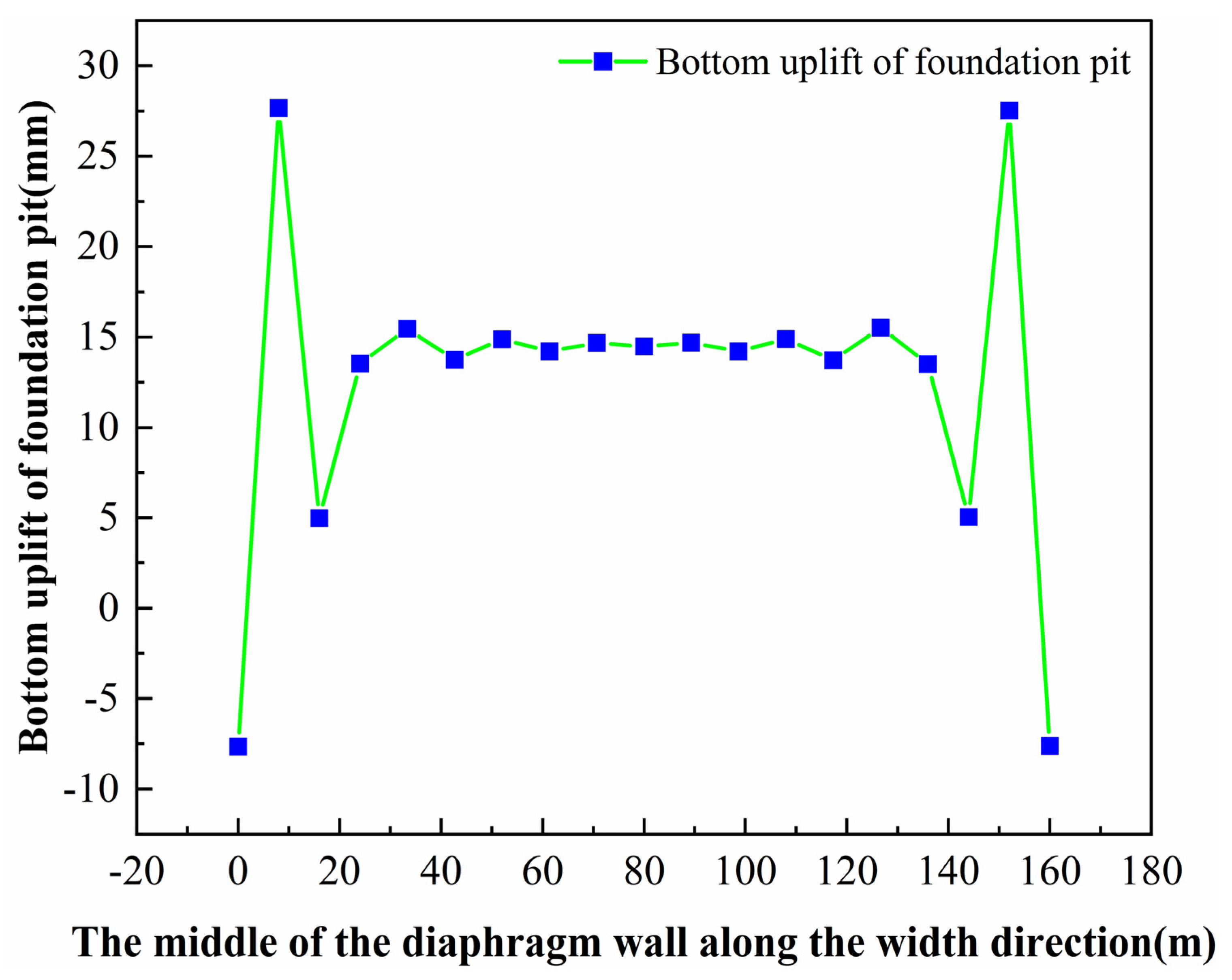
4.1.3. Change in Pit Bottom Elevation

The pit is excavated in layers to unload, and the soil at the bottom produces bulging deformation under the unloading action of layer-by-layer excavation, and the bulging deformation curve of the soil after the completion of the pit construction is as plotted in Figure 17. Due to the excavation of the soil body, the self-gravity stress generated by the soil above the excavation surface is released, resulting in the unloading rebound of the soil. After the excavation of the pit, the supporting structure is displaced to the inside of the pit, and the soil in the passive zone is similar to the state of triaxial tension, which generates the triaxial tensile shear deformation of the soil in the passive zone, resulting in the uplift of the bottom of the pit. Due to the constraint of soil rebound by the diaphragm wall, the minimum amount of bulge is observed at the corner edge of the pit, the maximum amount of bulge is at the centre of the pit, the bottom of the pit bulge is in the shape of the bottom of a rebated pot, and the maximum amount of bulge at this time is 28.2 mm.

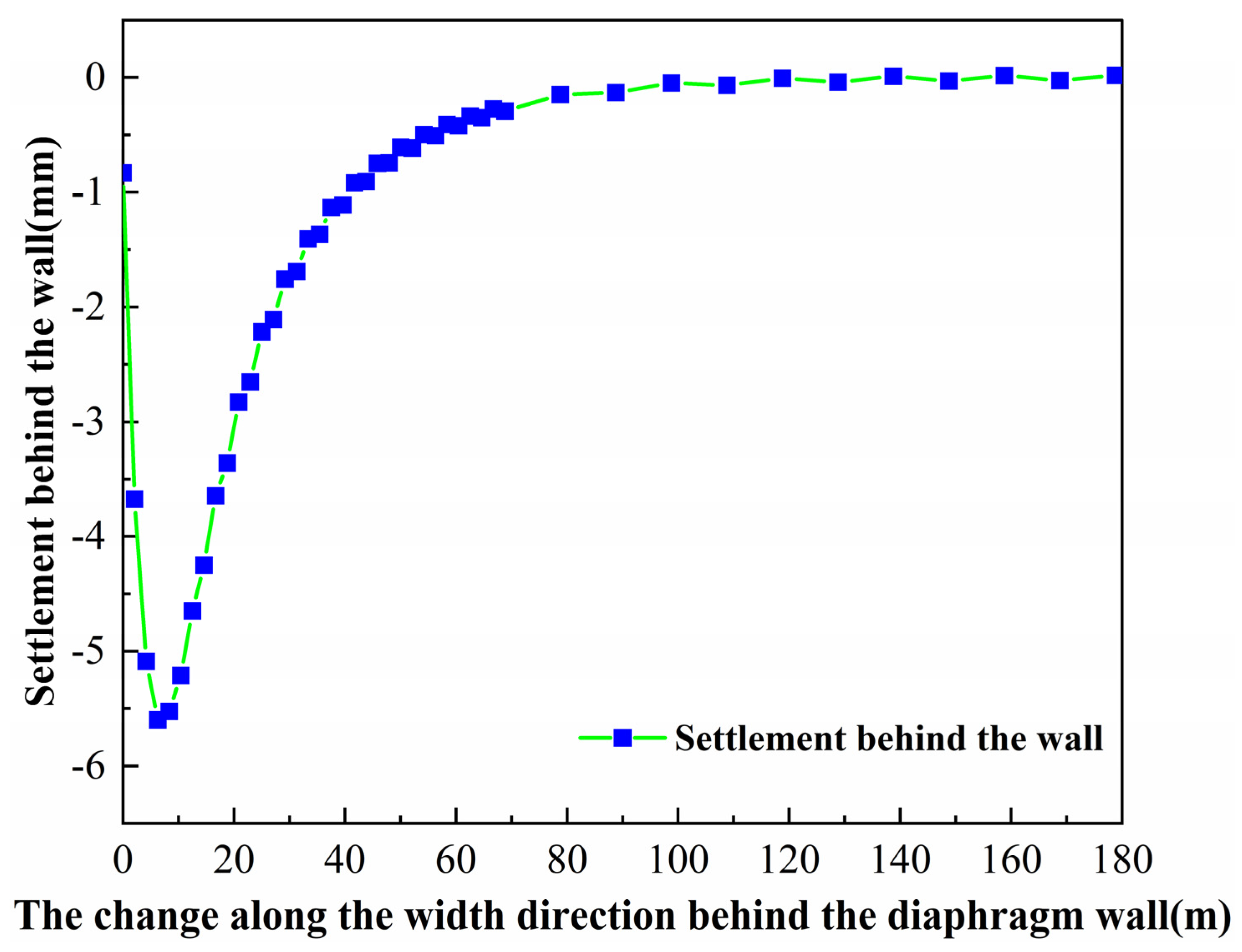
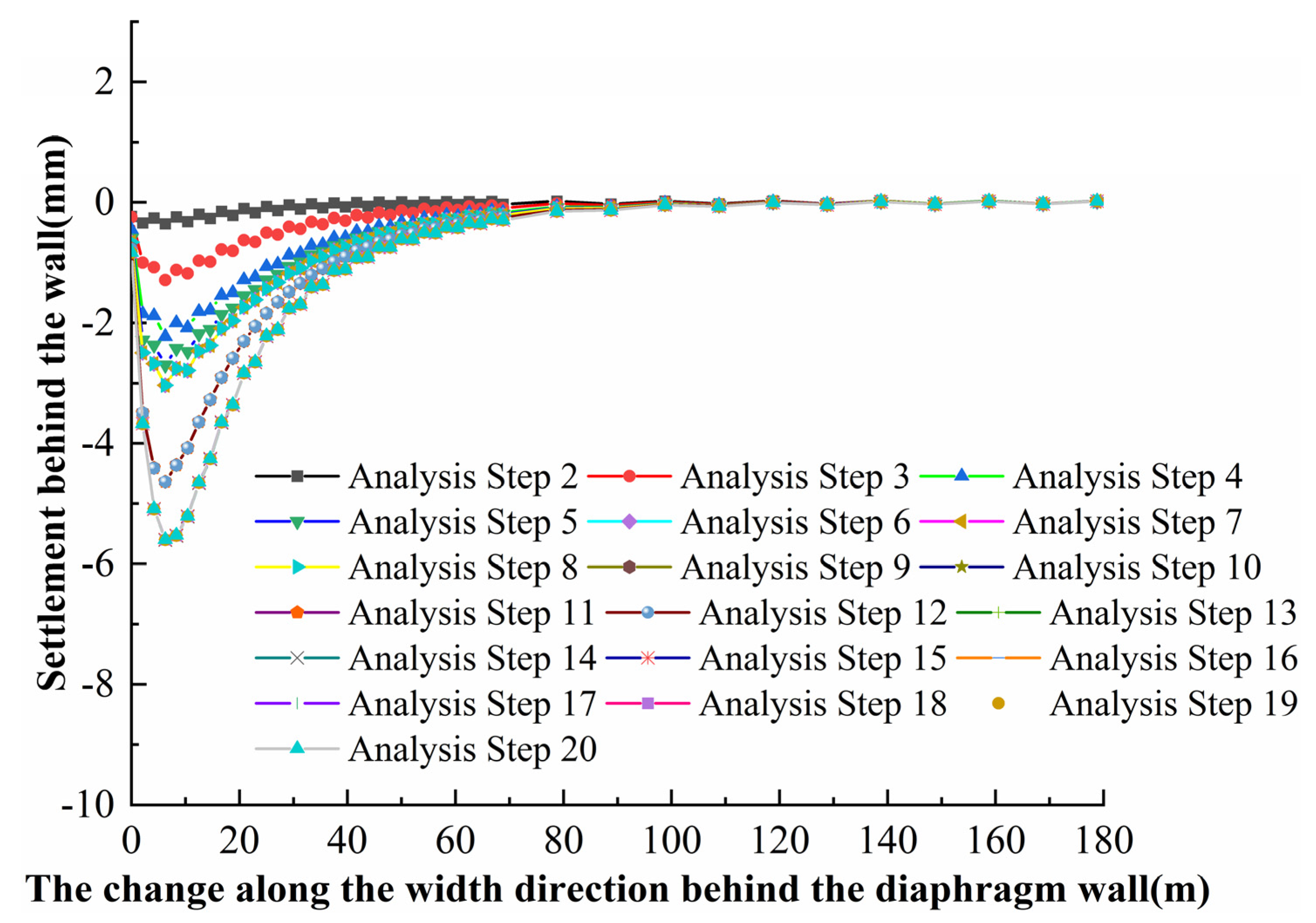
4.1.4. Change in Settlement Behind the Wall

The surface settlement pattern behind the wall of the foundation pit is related to the deformation characteristics of the support structure: when the horizontal displacement of the support structure caused by excavation in the early stages of the foundation pit is large and the horizontal displacement caused by excavation in the later stages is small, the horizontal displacement of the support structure tends to be in the form of a cantilever; if the support structure in the early stages is subjected to strong constraints, the horizontal displacement of the support structure caused by the excavation will be shifted to a deeper level. If the horizontal displacement of the support structure caused by excavation is well restrained in the pre-excavation period of the pit, the horizontal displacement of the support structure caused by excavation will be transferred to a deeper layer, and the surface settlement pattern after the wall will be of the notch type. The surface settlement data behind the wall in the central area after the excavation was completed were extracted and are plotted in Figure 18. Because of the good restraining effect of the supporting structure, the surface settlement behind the wall of the foundation pit is of the notch type. The surface settlement at 80 m from the pit is nearly 0. It can be assumed that the pit construction has an influence on the surface settlement in the direction of the width.
In Figure 19, the variation in post-wall surface settlement in the central region in different analysis steps is given to determine the deformation evolution pattern of the surface geotechnical bodies around the foundation pit. Similarly to the development of diaphragm wall horizontal displacement, regarding the surface settlement behind the wall in the second analysis step after the application of the diaphragm wall, along with the analysis step, the maximum settlement continues to grow until the fifth analysis step and reaches 2.8 mm; the subsequent analysis steps, 6–8, exhibit no further changes; in analysis step 9, due to the removal of the first layer of backpressure soil of the slope release and the two sides of the throat region of the soil body, and due to the soil body unloading, the maximum settlement changes to 4.7 mm; in analysis step 13, due to the removal of the second layer of backpressure soil and both sides of the throat region of the pit, the maximum settlement changes to 4.7 mm; and subsequently, there is almost no further change. During the pit excavation, the maximum surface settlement is maintained at a location approximately 7 m from the pit.

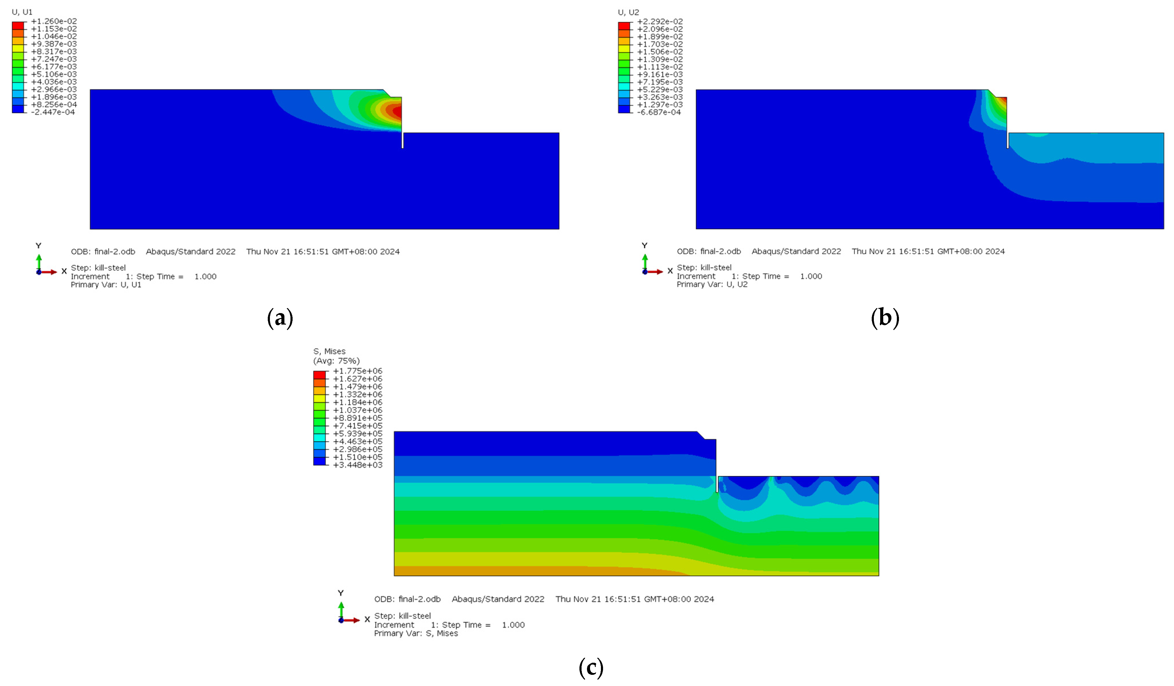
4.1.5. Changes in Soil Stress Force Field and Displacement Field

From the 10 m wide model of the central island area in the middle of the pit, the U1 cloud map and U2 cloud map of the soil displacement field after the construction was completed were output, as shown in Figure 20a,b. Due to the different assumption conditions, the 10 m wide pit model was excavated with one slope release instead of the vertical downward excavation in the whole-process model. From the figure, it can be seen that after the sloping excavation, the footing of the slope produces a significant pit bottom bulge due to the unloading rebound, with a maximum bulge value of 2.92 cm. This area is actually planned to be a ring road, which requires additional settlement monitoring points (e.g., level or fibre-optic sensors) in order to control the risk of differential settlement. In addition, the output of the soil von Mises stress map after the completion of construction is shown in Figure 20c, in which it can be seen that due to the presence of the engineering piles, the stress value of the soil below the footing has a certain degree of stress concentration near the piles, and the simulation results of the engineering piles are consistent with the site conditions, and it is recommended to optimise the spacing of the piles or to adopt pile-top reinforcement measures to alleviate the local stress concentration.

4.2. Numerical Simulation of the Whole Construction Process of Foundation Pit and Surrounding Structures

In deep foundation pit engineering, the stress redistribution caused by the unloading of the foundation pit excavation leads to the deformation of the surrounding soil body, which in turn breaks the initial stress balance of the neighbouring buildings and induces a structural internal force and displacement response. In a previous study, the deformation influence of pit excavation on the neighbouring metro station was revealed through numerical simulation: the maximum lateral displacement of the metro side wall reached 3.71 mm, and the sudden change in displacement was closely related to the large-scale unloading of the soil body. On this basis, this study further focuses on the coupling effect of multiple risk sources in complex environments, relying on the super-deep foundation pit project of Shenzhen Airport East Station, establishes a refined three-dimensional finite element model containing secondary environmental risk sources and tertiary environmental risk sources, and systematically simulates the whole construction process combining smooth and reversed covered digging and reversed work. By studying the cooperative deformation mechanism of the supporting structure, soil, and the surrounding buildings, we quantitatively analyse the spatial distribution characteristics of the group pile foundation settlement and the displacement of the side wall of the metro station to reveal the dynamic interaction mechanism of the deep and large foundation pit with the neighbouring structures, and to provide theoretical support for controlling the foundation pit deformation under a complex environment.

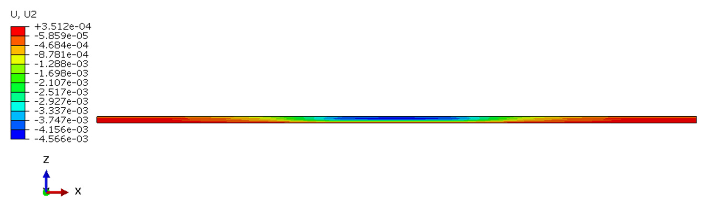
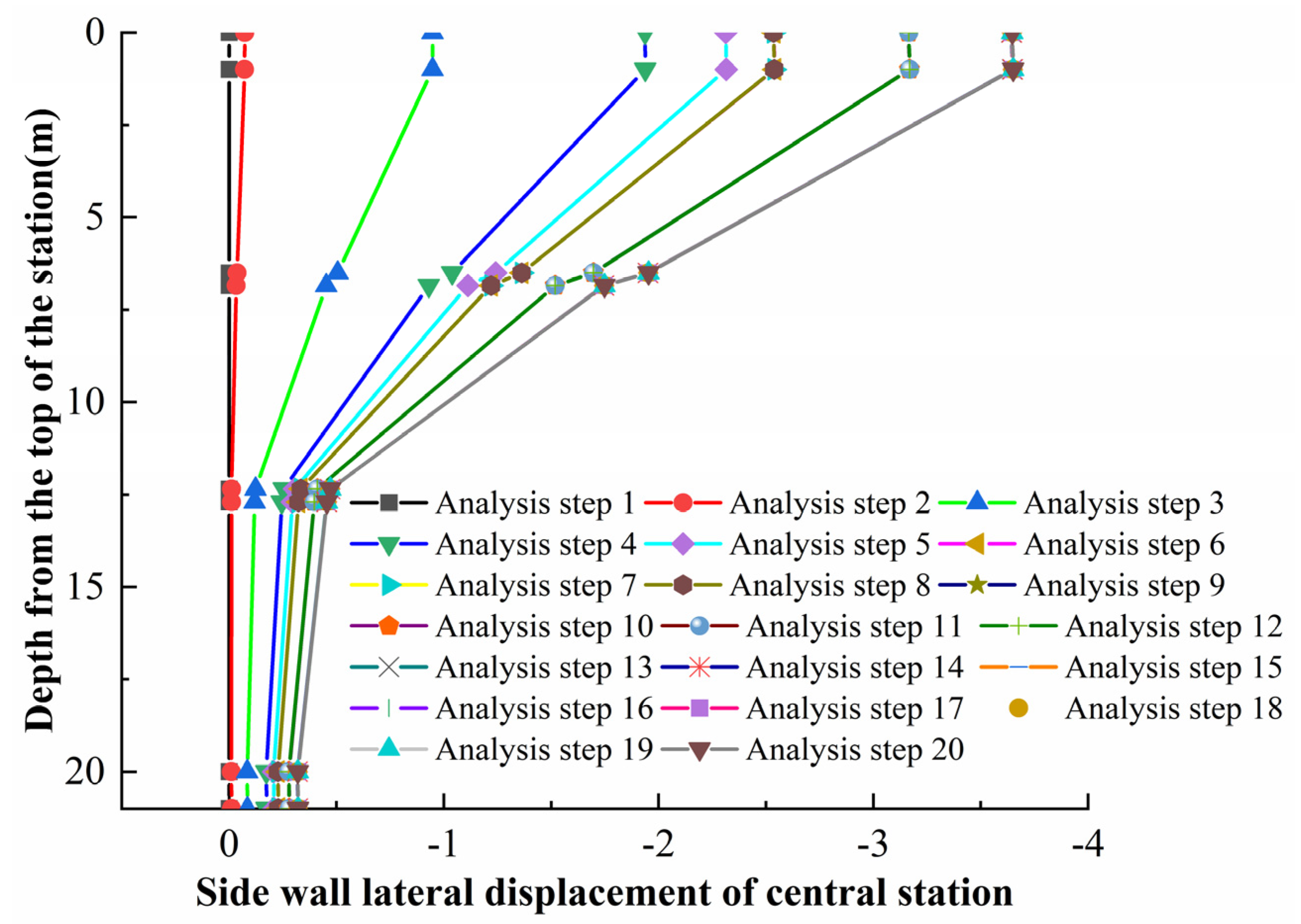
4.2.1. Deformation Characteristics of Side Walls in Metro Stations

According to the environmental investigation report around the project pit, the underground station Line 12 is 46 m away from the pit, the station side wall is 21 m high, covered by a 1 m thick soil layer, and it is an underground three-storey box structure. Figure 21 shows the lateral displacement cloud map of the side wall of the whole underground station, and the side wall within the central range of the pit side shift is the largest, which is due to the central soil unloading being much larger compared to the two sides of the throat area; this soil pressure distribution and ground-connecting wall side shift are also the largest in the whole excavation process of the pit, which accordingly causes the change in the station side shift cloud map.
The horizontal lateral displacements of the station side walls in the central region under each analysis step in the direction from the top of the station were extracted, as shown in Figure 22. The overall lateral displacement is concentrated at the top of 12.5 m, and with the pit construction, the lateral displacement gradually increases until the maximum lateral displacement of 3.71 mm. In addition, the analysis steps exhibiting large changes in lateral displacement are analysis steps 2–6, 9, and 12, and the process of these analysis steps is mostly accompanied by the large-scale unloading of the soil body. Although the specification does not stipulate the deformation requirements for buildings and structures in close proximity to the pit, for these buildings with special requirements for deformation, and with the construction and operation of a large number of subways in ever closer proximity to the pit adjacent to the underground already in operation, and even closer proximity to the pit adjacent to the high-speed railway, the deformation of the surrounding environment caused by the construction of the pit can be controlled up to millimetre-level requirements.
The maximum lateral displacement of the underground side wall is 3.71 mm, which is concentrated in the middle (12.5 m depth). The sudden change in displacement occurs at the step involving the mass unloading of the soil (e.g., analysis step 9), which is consistent with the trend predicted using the theoretical model.

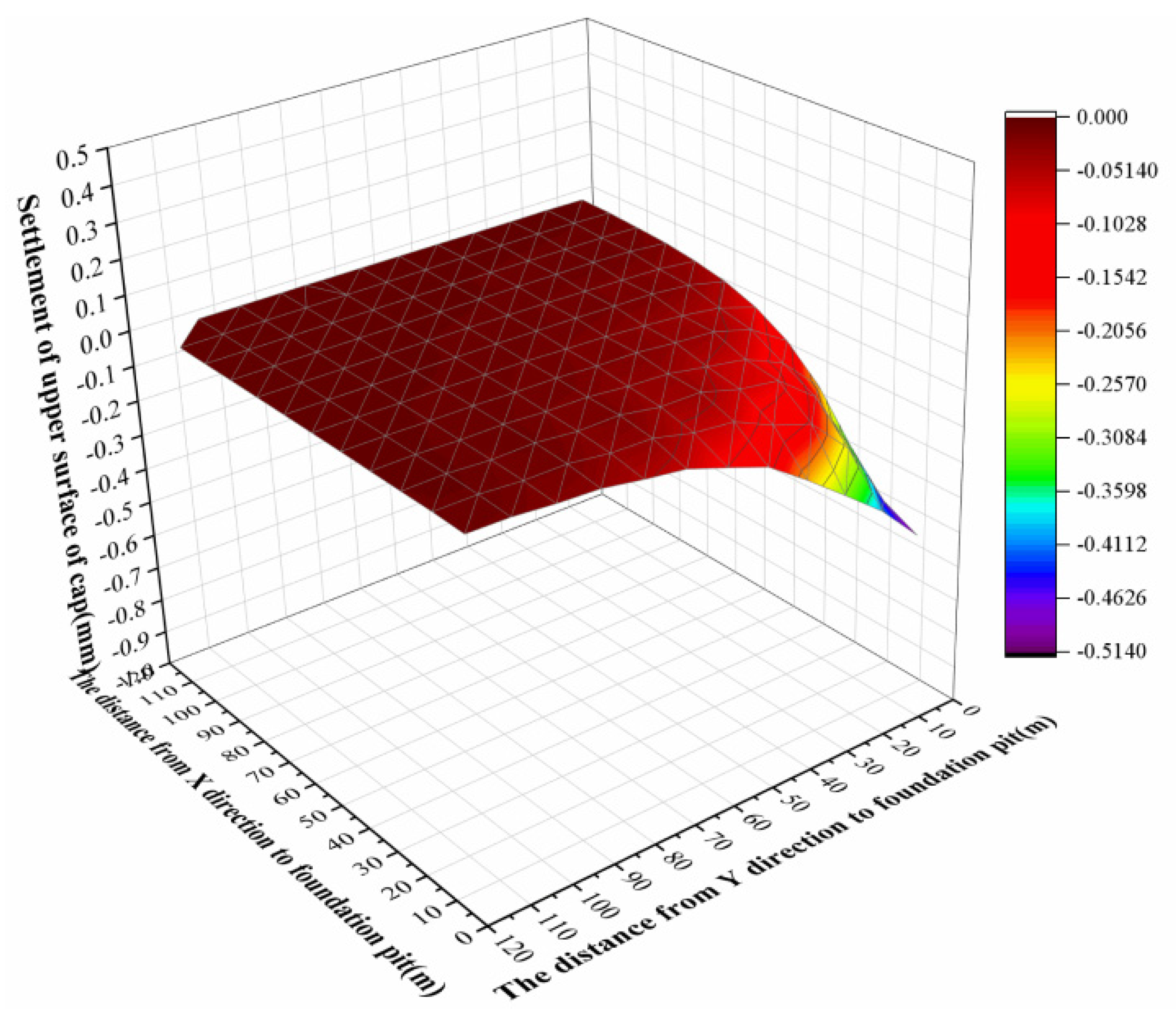
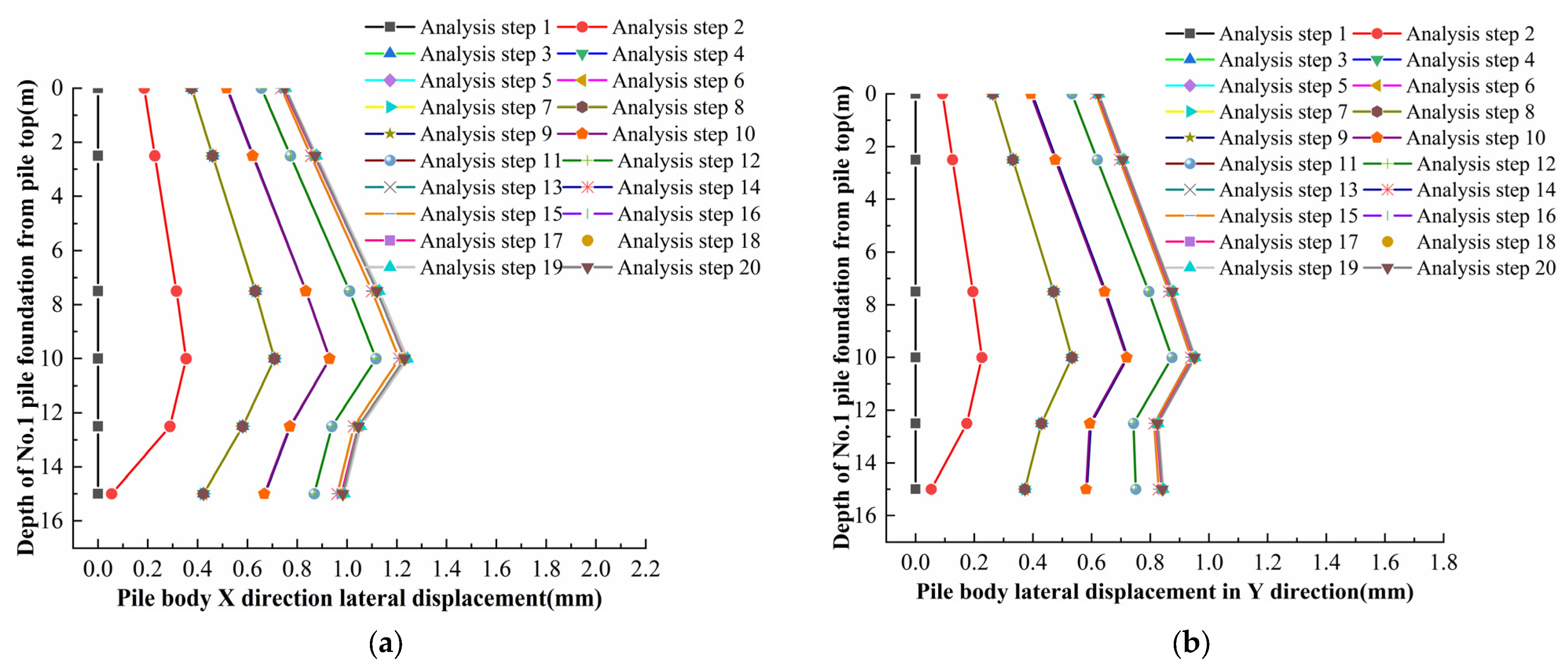
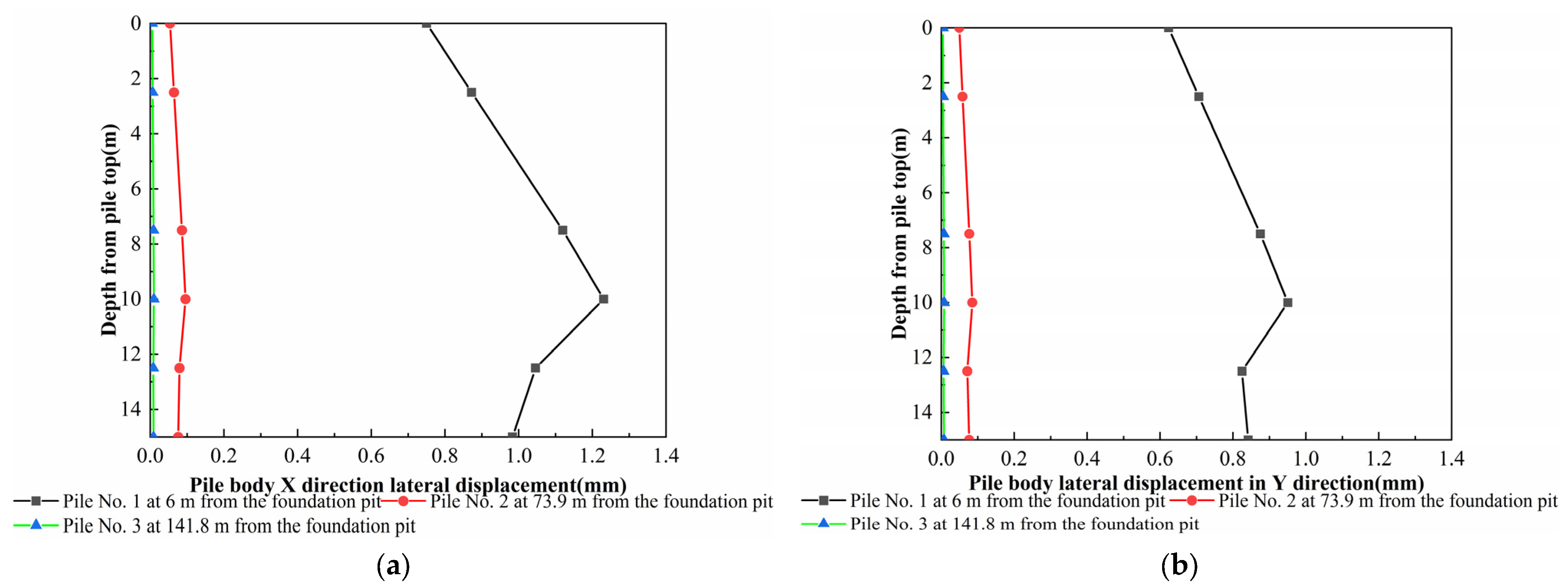
4.2.2. Settlement Evolution Law of Group Pile Foundation

The design drawings show that the Donghai Airlines administrative office building adopts a cast-in situ reinforced concrete frame structure, with one underground floor and seven aboveground floors (totalling eight floors); the building’s foundations, which adopt PHC pipe piles, are located in the northwest corner of the station pit, and the nearest distance from the main enclosure structure is 8.5 m, establishing the building as a secondary environmental risk source. The building is within a distance of two times the excavation depth of the foundation pit, rendering it affected by the unloading of the foundation pit excavation to a larger extent. We thus extracted the surface coordinates and vertical settlement data on the bearing platform of the group pile foundation and plotted the 3D surface map, as shown in Figure 23. The X-axis and Y-axis represent the distance from the northwest corner point of the foundation pit, and the graph shows that the vertical settlement of the corner point on the surface of the bearing platform close to the foundation pit is the largest, at 0.514 mm, and in the direction far away from the X-axis and the Y-axis, it rapidly recovers to a value in the vicinity of 0 mm.
The schematic diagrams of the group pile foundation and the locations of piles 1, 2, and 3 are given, as shown in Figure 24, in which the piles at a distance of 6 m, 73.9 m, and 184.1 m from the foundation pit corner are shown as piles 1, 2, and 3, respectively. In the following passages, we analyse the pile displacements at the three locations to investigate the deformation evolution law with regards to proximity for the group pile foundation.
The lateral displacement U1 of pile 1 under different analysis steps is shown in Figure 25a. From the activation of the soil model in analysis step 1, the activation of the group pile foundation model and metro station model, and the activation of the corresponding contact conditions, ground stress equilibrium was performed until the displacement was less than 10−7, and the construction of the ground-connecting wall was completed after the displacement becomes zero, and then the overall vertical undercutting of 2.7 m was performed in analysis step 3. This included the removal of the first layer of soil in the central island area and in the throat area on both sides, which resulted in a lateral displacement of the pile of 0.67 mm. The subsequent analysis steps 4–8 did not have a significant effect on pile 1 because the three sloping excavations of the pit were performed in the central area during these analysis steps, and due to the long sides of the ultra-narrow pit, the central area did not have any significant effect on the stress displacement field beyond the throat area on both sides. Due to the long sides of the ultra-narrow pit, the central area did not significantly affect the stress displacement field beyond the throat area on either side, and the subsequent application of the slab did not have an unloading effect. Analysis step 9 involved removes the first layer of sloping backpressure soil and removing the soil from both sides of the throat area to the second-floor slab; the group pile foundation was then affected by the removal of the soil from the throat area for unloading, resulting in stress displacement of the soil outside the pit, which in turn affected the piles, with a lateral displacement of about 0.91 mm. Similarly, analysis step 11 involved removing the soil from both sides of the throat area to the third-floor slab, and the lateral displacement of the piles reached 1.1 mm. Finally, following the completion of the pit construction, the maximum lateral movement reached 1.26 mm. In addition, the larger changes in the lateral movement of the pile were observed in the middle and lower parts of the pile, which have a consistent curve form during the pit construction.
The lateral movement U2 of pile 1 under different analysis steps is shown in Figure 25b, and its general deformation trend is consistent with the x-direction lateral movement trend in Figure 25a, and the maximum lateral movement reaches 0.93 mm at the end of the foundation construction.
To analyse the change rule of the pile body lateral displacement at different locations from the foundation pit, the pile body lateral displacements U1 and U2 of the piles at different locations were extracted, as shown in Figure 26a,b. As the distance away from the pit direction increases, the change in the maximum displacement of the pile body is significant, and the lateral displacement U1 of pile 1 near the pit is 1.26 mm, while the maximum lateral displacement U1 of pile 2 at a distance of 73.9 m is abruptly reduced to near 1 mm, until the lateral displacement of pile 3 at a distance of 141.8 m is almost unchanged. Similarly, for the lateral displacement U2, the variation is also significant. From this, it can be obtained that the lateral shift change in the group pile foundation outside the range of three times the excavation depth away from the foundation pit hardly needs to be considered, and the lateral shift change in the group piles within the range of three times the excavation depth can be prioritised to ensure the safety of the surrounding piles.
The maximum settlement of the group pile bearing platform is 0.514 mm, and the displacement gradient of the corner point near the foundation pit is significant. Pile 1 (6 m away from the foundation pit) shifts sideways by 1.26 mm, and the displacement of the pile body outside the range of three times the excavation depth is negligible, which verifies the spatial attenuation characteristic of the theoretical model.

5. Conclusions

(1)
Based on a model and construction process simulation, the deformation law of the support structure under the compliant–inverse combination method is revealed: the side shift in the ground wall is distributed in a ‘convex belly’ shape, with a maximum displacement of 29.98 mm, which is significantly affected by the shear stiffness of the soil body in the passive zone (the side shift is reduced by 11% when Ks = 0.1 Kw). The bottom bulge of the pit is in the shape of a backsliding pot, with a peak value of 28.2 mm, which is controlled by the embedding depth of the ground wall and the unloading path of the soil body.
(2)
The surface settlement behind the wall has an effect up to 3.8 times the excavation depth (80 m), with a maximum settlement of 5.7 mm, verifying the applicability of the plane strain assumption in the middle of the extra-long foundation pit.
(3)
The maximum lateral displacement of the underground side wall is 3.71 mm, which is concentrated in the depth range of 12.5 m in the middle of the foundation pit, and the sudden change in displacement mainly occurs in the stage of large-scale unloading of the soil body (e.g., step 9 of the analysis), which verifies the spatial attenuation characteristics of the theoretical model of stress redistribution.
(4)
Settlement evolution law of group pile foundation: The maximum settlement of the group pile bearing platform is 0.514 mm, and the displacement gradient of the corner point near the foundation pit is significant. The lateral displacement of pile 1 (6 m away from the foundation pit) is up to 1.26 mm, while the displacement of piles outside the range of three times the excavation depth is negligible, which indicates that the influence range of the deformation has an obvious spatial limitation.
(5)
Validation of model applicability: By comparing the evolution law of pile lateral displacement and metro station displacement at different construction stages, the simulation results are found to be consistent with the theoretical prediction trend, which confirms the applicability of the 3D refinement model in complex environment foundation pit engineering.

Author Contributions

Writing—review and editing, C.G. (Chao Guo); supervision, writing—review and editing, X.Y. and C.G. (Chengchao Guo); writing—review, P.L. All authors have read and agreed to the published version of the manuscript.

Funding

This work was supported by the Science and Technology Program of Guangzhou Municipal Construction Group Co., Ltd., China (Grant No. 2022-KJ004).

Data Availability Statement

The data presented in this study are available within this article.

Acknowledgments

We would like to thank the authors for their contributions to this paper.

Conflicts of Interest

The authors declare no conflicts of interest.

References

  1. Han, K.; Zhai, Z.; Chen, X.; Zhang, C.; Ju, J.-W.W.; Bao, X.; Wang, S.; Hou, B. A methodology for evaluating the safety resilience of the existing tunnels induced by foundation pit excavation. Tunn. Undergr. Space Technol. 2025, 158, 106362. [Google Scholar] [CrossRef]
  2. Li, Y.J.; Zhou, Z.; Alcalá, J.; Yepes, V. Research on spatial deformation monitoring and numerical coupling of deep foundation pit in soft soil. J. Build. Eng. 2025, 99, 111636. [Google Scholar] [CrossRef]
  3. Farzi, M.; Pakbaz, S.M.; Aminpour, A.H. Selection of support system for urban deep excavations: A case study in Ahvaz geology. Case Stud. Constr. Mat. 2018, 8, 131–138. [Google Scholar] [CrossRef]
  4. Ge, C.; Yang, M.; Li, P.; Zhang, M. Influence of deep foundation pit excavation on surrounding environment: A case study in Nanjing, China. Acta Geophys. 2024, 73, 495–516. [Google Scholar] [CrossRef]
  5. Lei, Z.; Wang, Y.; Zhang, Y.; Gu, F.; Zan, Z.; Mei, Y.; Liu, W.; Zhou, D. Advanced Risk Assessment for Deep Excavation in Karst Regions Using Improved Dempster–Shafer and Dynamic Bayesian Networks. Buildings 2024, 14, 3022. [Google Scholar] [CrossRef]
  6. Xu, C.; Hou, J.; Liu, B.; Lei, F.; Song, L. Research on Coordinated Relationship Between Deformation and Force in Shaft Foundation Pit Support Structures. Buildings 2024, 14, 3438. [Google Scholar] [CrossRef]
  7. Han, M.; Chen, X.; Jia, J.; Tu, B. Coupled Analytical Method for Braced Excavation Based on the Pasternak Foundation Model and Nonlinear p–y Curve Model. Int. J. Geomech. 2024, 24, 04024180. [Google Scholar] [CrossRef]
  8. Jin, T.; Zhang, P.; Niu, Y.; Lv, X. Integrating Combination Weighting of Game Theory and Fuzzy Comprehensive Evaluation for Selecting Deep Foundation Pit Support Scheme. Buildings 2024, 14, 619. [Google Scholar] [CrossRef]
  9. Xu, Q.; Xie, J.; Lu, L.; Wang, Y.; Wu, C.; Meng, Q. Numerical and theoretical analysis on soil arching effect of prefabricated piles as deep foundation pit supports. Undergr. Space 2024, 16, 314–330. [Google Scholar] [CrossRef]
  10. Dong, J.; Chen, C.; Dong, M.; Lu, B.; Guan, Y.; Zhao, W. Influence of disturbance degree on the propped excavation stability in sandy soil in Shenyang, China. Undergr. Space 2023, 10, 150–165. [Google Scholar] [CrossRef]
  11. Issa, U.; Saeed, F.; Miky, Y.; Alqurashi, M.; Osman, E. Hybrid AHP-Fuzzy TOPSIS Approach for Selecting Deep Excavation Support System. Buildings 2022, 12, 295. [Google Scholar] [CrossRef]
  12. Chen, B.; Yan, T.; Song, D.; Luo, R.; Zhang, G. Experimental investigations on a deep excavation support system with adjustable strut length. Tunn. Undergr. Space Technol. 2021, 115, 104046. [Google Scholar] [CrossRef]
  13. Chen, F.; Miao, G.; Lai, F. Base Instability Triggered by Hydraulic Uplift of Pit-in-Pit Braced Excavations in Soft Clay Overlying a Confined Aquifer. KSCE J. Civ. Eng. 2020, 24, 1717–1730. [Google Scholar] [CrossRef]
  14. Chen, S.; Zeng, N.; Li, F.; Yue, H.; Wang, Q.; Li, Q. Proactive Safety Risk Control System for Deep Foundation Pit Construction: Situational Tailoring of Integrated Cybernetics and Dual-System Theory. J. Constr. Eng. Manag. 2025, 151, 04025018. [Google Scholar] [CrossRef]
  15. Wang, Z.; Shen, X.; Tian, X.; Song, Z.; Zhou, P. Study on the Influence and Deformation Control of Rich Water Foundation Excavation on Adjacent Buildings. Buildings 2024, 15, 52. [Google Scholar] [CrossRef]
  16. Sun, L.; Liu, S.; Zhang, L.; He, K.; Yan, X. Prediction of the displacement in a foundation pit based on neural network model fusion error and variational modal decomposition methods. Measurement 2025, 240, 115534. [Google Scholar] [CrossRef]
  17. Huang, G.; Liu, Z.; Wang, Y.; Yang, Y. A Multi-Objective Prediction XGBoost Model for Predicting Ground Settlement, Station Settlement, and Pit Deformation Induced by Ultra-Deep Foundation Construction. Buildings 2024, 14, 2996. [Google Scholar] [CrossRef]
  18. Tang, W.; Tang, L.; Ling, X.; Kong, X.; Zhang, Y. Long-term performance of subway tunnels induced by the symmetrical excavation of semicircular deep foundation pits in the Northeast Region hard silty clay. Tunn. Undergr. Space Technol. 2024, 154, 106052. [Google Scholar] [CrossRef]
  19. Xu, X.; Liang, Y.; Wang, M.; Hu, Q.; Xue, D. Analysis of water inrush of a deep excavation triggered by river bank failure and its reconstruction. Eng. Fail. Anal. 2024, 165, 108729. [Google Scholar] [CrossRef]
  20. Li, S.; Sun, X.; Shi, C.; Kang, R.; Yang, F. Dynamic response and regular analysis of adjacent buildings under blasting construction across foundation pits of subway stations. Structures 2024, 66, 106903. [Google Scholar] [CrossRef]
  21. Guo, Y.; Li, C.; Yan, M.; Ma, R.; Bi, W. Research on Deformation Safety Risk Warning of Super-Large and Ultra-Deep Foundation Pits Based on Long Short-Term Memory. Buildings 2024, 14, 1464. [Google Scholar] [CrossRef]
  22. Liu, B.; Zhang, D.; Wang, Y.; Wang, N.; Xu, W. Design optimization and observed performance of a super-large foundation pit excavation subjected to unsymmetrical loading in water-rich floodplain: A case study. Soils Found. 2023, 63, 101329. [Google Scholar] [CrossRef]
  23. Guan, L.L.; Chen, Y.G.; Liao, R. Accuracy Analysis for 3D Model Measurement Based on Digital Close-range Photogrammetry Technique for the Deep Foundation Pit Deformation Monitoring. KSCE J. Civ. Eng. 2022, 27, 577–589. [Google Scholar] [CrossRef]
  24. Wang, K.; Gao, Y.; Jin, Z.; Zhou, X.; Chen, L.; Zhang, C. Research on stability of steep bank slope and reserved thin-walled rock cofferdam during excavation of intake foundation pit. Eng. Fail. Anal. 2022, 141, 106659. [Google Scholar] [CrossRef]
  25. Ren, D.; Kang, C.; Liu, H.; Li, Y.; Wang, J. Characteristics of a Large-Scale Deep Foundation Pit Excavated by the Central-Island Technique in Chengdu Soft Clay. KSCE J. Civ. Eng. 2022, 26, 2610–2623. [Google Scholar] [CrossRef]
  26. Shi, J.; Liu, G.; Huang, P.; Ng, C.W.W. Interaction between a large-scale triangular excavation and adjacent structures in Shanghai soft clay. Tunn. Undergr. Space Technol. 2015, 50, 282–295. [Google Scholar] [CrossRef]
  27. Tan, Y.; Li, X.; Kang, Z.; Liu, J.; Zhu, Y. Zoned excavation of an oversized pit close to an existing metro line in stiff clay: Case Study. J. Perform. Constr. Facil. 2015, 29, 04014158. [Google Scholar] [CrossRef]
  28. Chen, H.H.; Li, J.P.; Li, L. Performance of a Zoned Excavation by Bottom-Up Technique in Shanghai Soft Soils. J. Geotech. Geoenviron. Eng. 2018, 144, 05018003. [Google Scholar] [CrossRef]
  29. Zeng, F.-Y.; Zhang, Z.-J.; Wang, J.-H.; Li, M.-G. Observed Performance of Two Adjacent and Concurrently Excavated Deep Foundation Pits in Soft Clay. J. Perform. Constr. Facil. 2018, 32, 04018040. [Google Scholar] [CrossRef]
  30. Li, D.; Ma, J.; Wang, C.; Gao, X.; Fang, M. A New Method for Piping Risk Evaluation on Unconfined Aquifers under Dewatering of Deep Foundation Pits. KSCE J. Civ. Eng. 2022, 26, 3275–3286. [Google Scholar] [CrossRef]
  31. Guo, P.; Gong, X.; Wang, Y.; Lin, H.; Zhao, Y. Analysis of observed performance of a deep excavation straddled by shallowly buried pressurized pipelines and underneath traversed by planned tunnels. Tunn. Undergr. Space Technol. 2023, 132, 104946. [Google Scholar] [CrossRef]
  32. Li, Y.; Yao, A.; Li, H.; Gong, Y.; Tian, T. Calculation method of multi-stage earth pressure for foundation excavation considering excavation process. Acta Geotech. 2023, 18, 6123–6141. [Google Scholar] [CrossRef]
  33. Hu, H.; Tian, Y.; Zheng, N.; Du, X.; Guo, H.; Xu, Z. Numerical Simulation on an Ultra-Large Seven-Ring Internal Support System Considering the Effects of Soil–Structure Interaction and Temperature. Buildings 2025, 15, 463. [Google Scholar] [CrossRef]
  34. Zeng, C.F.; Wang, S.; Xue, X.L.; Zheng, G.; Mei, G.X. Characteristics of ground settlement due to combined actions of groundwater drawdown and enclosure wall movement. Acta Geotech. 2022, 17, 4095–4112. [Google Scholar] [CrossRef]
  35. Wang, J.; Long, Y.; Gao, F.; Wang, H.; Shi, Y.; Yang, T.; Liu, X.; Huang, X.; Xu, N. Transparent soil test evaluation of vertical–horizontal mixed curtain during dewatering. Acta Geotech. 2022, 17, 3293–3313. [Google Scholar] [CrossRef]
  36. Tu, B.; Han, M.; Jia, J.; Xiao, Z.; Liu, L. Improved Mobilized Strength Design Method for Multi-Support Excavation Deformation Analysis. Buildings 2024, 14, 3630. [Google Scholar] [CrossRef]
  37. Finno, R.J.; Kim, S.; Lewis, J.; Van Winkle, N. Observed Performance of a Sheetpile-Supported Excavation in Chicago Clays. J. Geotech. Geoenviron. Eng. 2019, 145, 05018005. [Google Scholar] [CrossRef]
  38. Mu, L.; Huang, M.; Finno, J.R. Tunnelling effects on lateral behavior of pile rafts in layered soil. Tunn. Undergr. Space Technol. 2012, 28, 192–201. [Google Scholar] [CrossRef]
  39. Shi, Z.; Buscarnera, G.; Finno, J.R. Simulation of cyclic strength degradation of natural clays via bounding surface model with hybrid flow rule. Int. J. Numer. Anal. Methods Geomech. 2018, 42, 1719–1740. [Google Scholar] [CrossRef]
  40. Shi, Z.; Finno, J.R.; Buscarnera, G. A hybrid plastic flow rule for cyclically loaded clay. Comput. Geotech. 2018, 101, 65–79. [Google Scholar] [CrossRef]
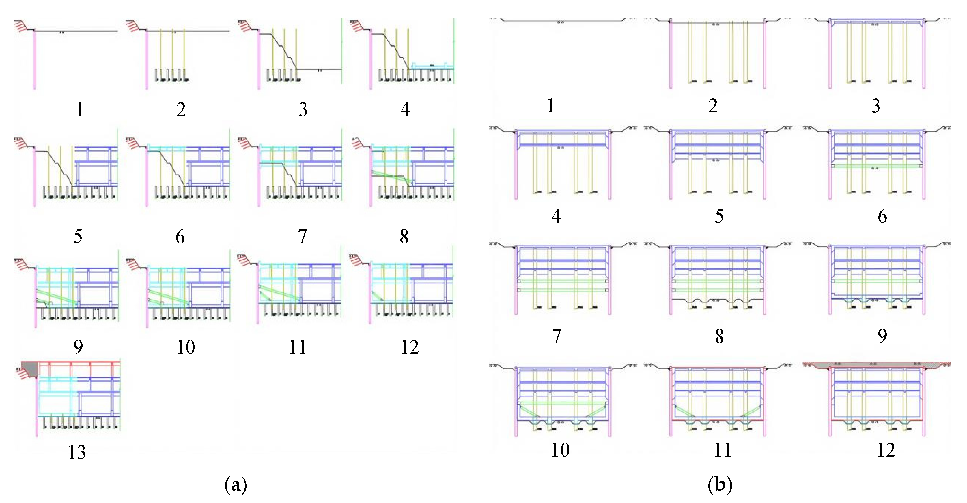
Figure 1. Surroundings and buildings.
Buildings 15 01435 g001
Figure 2. Surrounding structures.
Buildings 15 01435 g002
Figure 3. Three-dimensional figure of the pit.
Buildings 15 01435 g003
Figure 4. Station pit construction plan.
Buildings 15 01435 g004
Figure 5. Schematic diagram of the construction area. (a) Schematic map of the central region. (b) Schematic representation of the pharyngeal region on both sides.
Buildings 15 01435 g005
Figure 6. Pit construction excavation procedure diagram. (a) Schematic diagram of the central subregion. (b) Excavation process diagram for construction of both sides of the throat area.
Buildings 15 01435 g006
Figure 7. Construction flow chart.
Buildings 15 01435 g007
Figure 8. Finite element modelling of the most dangerous sections. (a) Earth. (b) Support structure.
Buildings 15 01435 g008
Figure 9. Model of the whole construction process with identified risk sources.
Buildings 15 01435 g009
Figure 10. Finite element model of each part. (a) Earth. (b) Support structure. (c) Mass pile foundation. (d) Metro station.
Buildings 15 01435 g010
Figure 11. Lateral movement of the ground-connecting wall in the centre of the pit in different analysis steps.
Buildings 15 01435 g011
Figure 12. Diaphragm wall diagram after the completion of foundation pit constructions. (a) Horizontal displacement trend diagram of diaphragm wall. (b) The von Mises stress cloud diagram of diaphragm wall.
Buildings 15 01435 g012
Figure 13. Lateral movement of the ground wall along the length of the ground wall at a depth of 13 m from the top of the wall.
Buildings 15 01435 g013
Figure 14. Depth direction of the central part of the pit along the diaphragm wall in different analysis steps. (a) Lateral movement of the ground wall along the depth of the ground wall. (b) The von Mises stresses in ground-connected walls along the depth of ground-connected walls.
Buildings 15 01435 g014
Figure 15. Clouds of lateral movement in the ground-connected wall under each key analysis step. (a) Analysis step 2. (b) Analysis step 3. (c) Analysis step 4. (d) Analysis step 5. (e) Analysis step 6. (f) Analysis step 9. (g) Analysis step 13. (h) Analysis step 15.
Buildings 15 01435 g015
Figure 16. The von Mises stress cloud of the ground-connected wall under each critical analysis step. (a) Analysis step 2. (b) Analysis step 3. (c) Analysis step 4. (d) Analysis step 5. (e) Analysis step 6. (f) Analysis step 9. (g) Analysis step 13. (h) Analysis step 15. (i) Analysis step 17. (j) Analysis step 19.
Buildings 15 01435 g016
Figure 17. Amount of pit bottom rise along the width of the central island area.
Buildings 15 01435 g017
Figure 18. Surface settlement behind wall in central area after completion of excavation.
Buildings 15 01435 g018
Figure 19. Surface settlement behind the wall in the central region in different analysis steps.
Buildings 15 01435 g019
Figure 20. Cloud view of the soil after construction is complete. (a) Schematic of the U1 cloud diagram. (b) Schematic U2 cloud diagram. (c) Schematic diagram of von Mises stress clouds.
Buildings 15 01435 g020
Figure 21. Lateral displacement cloud map of side walls in metro stations.
Buildings 15 01435 g021
Figure 22. Lateral movement of the station side walls in the central region of each analysis step in the direction away from the top of the station.
Buildings 15 01435 g022
Figure 23. Schematic diagram of the surface settlement on the bearing platform of the group pile foundation.
Buildings 15 01435 g023
Figure 24. Schematic diagram of group pile foundation and locations of piles 1, 2, and 3.
Buildings 15 01435 g024
Figure 25. Lateral movement of pile no. 1 under different analysis steps. (a) Lateral movement U1 of pile no. 1. (b) Lateral movement U2 of pile no. 1.
Buildings 15 01435 g025
Figure 26. Lateral movement of pile nos. 1–3 at different locations after the end of pit construction. (a) Lateral movement U1 of piles in x-direction. (b) Lateral movement U1 of piles in y-direction.
Buildings 15 01435 g026
Table 1. Construction steps in the central region.
StageBrief Description of Construction ContentCore Operations and Instructions
1Site levelling and initial constructionSlope excavation to top of crown beam, slope hardening, diaphragm wall application
2Temporary structure and earthwork excavationApply temporary columns and anti-drawing piles in the reverse zone; excavate to the bottom of the crown beam and apply crown beam and water retaining cans
3Base excavationSloping excavation to base
4Foundation construction of central islandApplication of central island jacking piles and footings
5The main structure of reverse constructionBottom-up construction B2 → B1 floor slab, reserved wall columns
6Structure construction in soil-remaining areaBeams and slabs at B1 level in soil retention area, columns to be retained in accordance with the reversal of the work
7Layered excavation and support constructionExcavate to B2 level elevation, apply B2 floor slab and columns on beams
8The first supporting systemExcavation to first support, partial trenching for concrete support
9The second support systemExcavation to second support, partial trenching for concrete support
10Base structure constructionExcavate to footing, apply footing for retained area and side walls below second support
11Support removal and support replacementRemoval of second brace, construction of side wall between two braces, erection of replacement brace
12Support system conversionRemoval of the first support and construction of the side wall between the two supports
13The final structure construction and endingApplication of B1 main body, backfilling of fertiliser tanks, removal of replacement braces and temporary columns
Table 2. Construction steps for both sides of the throat area.
StageBrief Description of Construction ContentKey Processes and Instructions
1Site levelling and initial excavationSite levelling; slope release excavation to top of crown beam, slope hardening
2Infrastructure constructionApply diaphragm walls, steel pipe columns and foundation piles; excavate below the bottom of crown beams, apply crown beams and retaining barriers
3Roof constructionApply structural roof
4B1 layer structure constructionExcavate down to B1 level elevation, construct B1 floor slab and side walls
5B2 layer structure constructionContinue excavation down to B2 floor elevation, construct B2 floor slab and side walls
6The first supporting systemExcavate to the location of the first concrete support and apply the first concrete support
7The second support systemExcavate to the location of the second concrete support and apply the second concrete support
8Base construction preparationExcavate to base, apply bedding and waterproofing layer
9Demolition of base plate and supportConstruction of base slab and side wall below second support; removal of second concrete support
10Support change and side wall endingConstruction of the remaining side wall below the second brace; erection of steel braces to replace braces
11Support system conversionRemoval of first concrete support; construction of side wall between two supports
12Ending and covering soilRemoval and replacement of braces; construction of waterproofing layer on the roof slab and backfilling with overburden
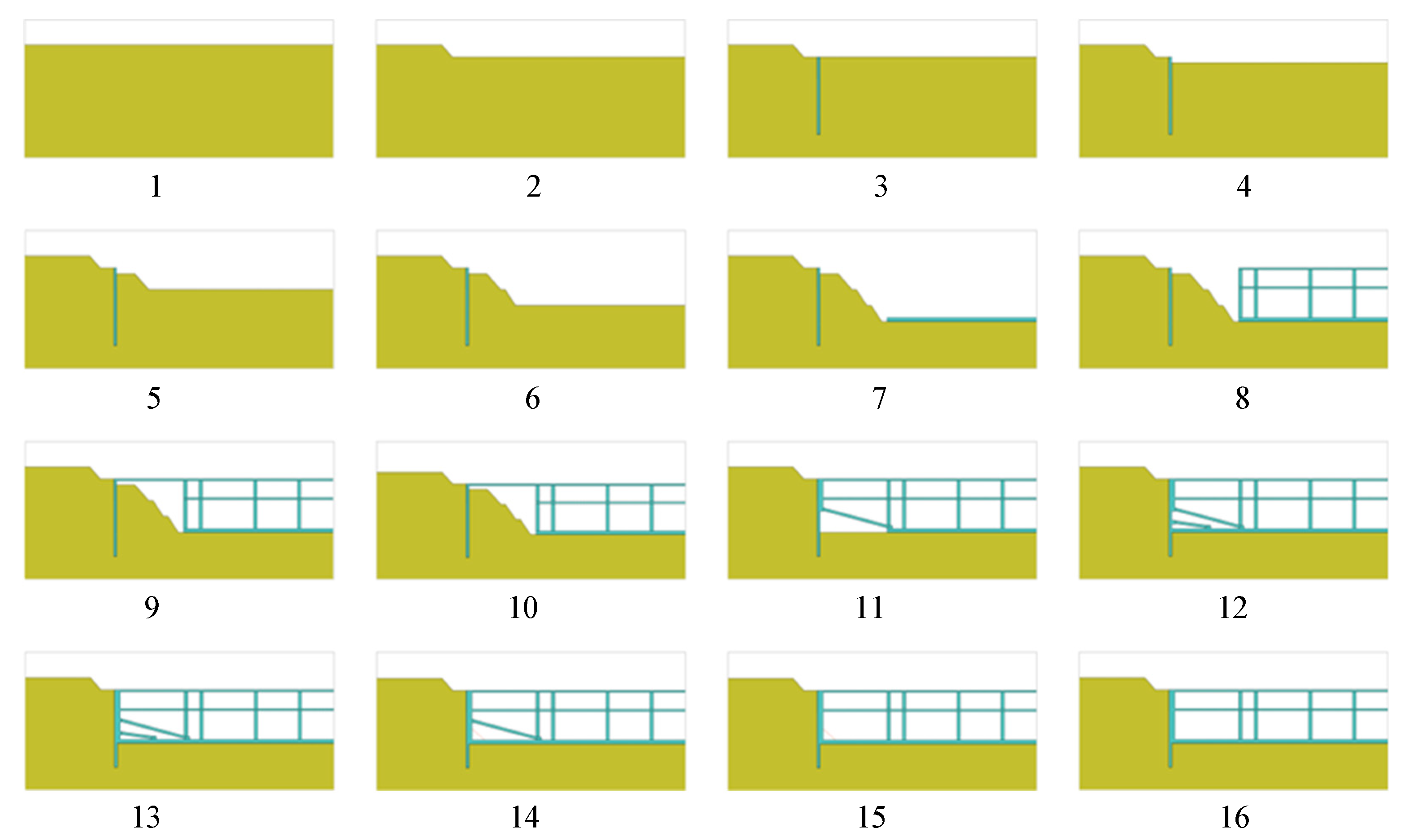
Table 3. Construction process flow and analysis step setup.
Working ConditionAnalysis StepContents of Construction
11Levelling site
22Slope excavation 4.5 m
33Construction of underground continuous wall
44Dig 2.2 m vertically
55Slope excavation 6 m
66Slope excavation 6 m
77The slope excavation is 6.08 m, and the structural floor in the middle of the central island is applied
88
9
The main structure of the middle part of the central island constructed via the sequential construction method
910Construction soil area B1 floor
1011
12
Excavate to the elevation of the B2 floor, and apply the B2 floor in the soil area and the side wall between the two floors
1113Excavation to the floor elevation, construction of the first layer of concrete support
1214
15
The bottom plate of the soil retention area is applied and the second layer of concrete support is applied
1316The side wall between the B2 floor and the bottom plate is applied
1417Remove the second layer of concrete support and use it as steel support
1518Remove the first layer of concrete support
1619Steel support removed; construction completed
Table 4. Properties of the soil and rock layers.
Soil Layer NumberNameThickness (m)Density (kg/m3)Elastic Modulus (MPa)Poisson RatioAngle of Friction (°)Angle of Dilatancy (°)Force of
Cohesion (Pa)
1Miscellaneous fill4185050.3120.110,000
2Silty clay21650200.35.120.112,200
3Silty clay21890200.3616.120.136,400
4Rock granite 1352350700.25300.143,000
5Rock granite 237262030000.2400.12,000,000
Table 5. Material parameters of supporting structure and main structure.
NameSectional Dimension (m × m)Density (kg/m3)Elastic Modulus (MPa)Poisson Ratio
Diaphragm wall1.2 × 10250040,0000.2
Side wall1.3 × 10250040,0000.2
B1 floor0.7 × 10250040,0000.2
B2 floor0.7 × 10250040,0000.2
Structural floor1.5 × 10250040,0000.2
Engineering pile1.5 × 2250040,0000.2
The first layer of concrete braces1 × 1250040,0000.2
The second layer of concrete braces1 × 1250040,0000.2
Steel inverted braceΦ 0.4 × 0.027800210,0000.3
Table 6. Support structure and main structure material parameters.
DesignationSection Size (m)Density (kg/m3)Modulus of Elasticity (MPa)Poisson’s Ratio
Diaphragm wallT1.2250040,0000.2
Side wallT1.3250040,0000.2
Central island floor slab 1T0.5250040,0000.2
Central island floor slab 2T1250040,0000.2
Floor slabs in both throat areas 1T0.5250040,0000.2
Floor slabs in both throat areas 2T1250040,0000.2
Structural floorT1.5250040,0000.2
First layer of concrete inverted support1 × 1250040,0000.2
Second layer of concrete inverted support1 × 1250040,0000.2
Steel inverted propΦ 0.4 × 0.027800210,0000.3
Internal concrete support in the throat Area on both sidesT1250040,0000.2
Group pile foundation model\250040,0000.2
Metro station models\250040,0000.2
Table 7. Pit excavation simulation steps.
StageBrief Description of Construction ContentsKey Processes and Instructions
1Model Initialisation and Ground Stress EquilibriumActivation of soil, pile foundation, and station models; ODB method to balance ground stresses
2Diaphragm wall constructionActivation of ground and barrier walls
3–6Layered earth excavationVertical undercutting 2.7 m → three times the sloping excavation
7–8Central island and ground-floor structureFloor slab in the middle of the central island → ground-floor slab in the reverse work area and throat area
9–10Construction of the second level of the structureRemoval of the first layer of backpressure → excavation to the second layer of elevation → application of the second layer of floor slabs in the backworking and throat areas
11–12Construction of the third-floor structureExcavation to the third-floor level → application of the third-floor slab in the throat area
13–14Initial construction of the support systemRemoval of the second layer of backpressure → excavation below the first support → application of the third-floor slab in the reverse zone and the first concrete support in the throat zone
15Base excavation and installation of diagonal bracingExcavation of the central island to the base → activation of the base plate → application of the first and second layers of diagonal casting struts
16–17Deep excavation and support in the throat areaExcavation to below the second support → application of the second concrete support → excavation to the footing and activation of the base plate in the throat area
18–20Support removal and finishingRemoval of diagonal throw braces and concrete supports → activation of steel pipe replacement braces → final removal of replacement braces
Disclaimer/Publisher’s Note: The statements, opinions and data contained in all publications are solely those of the individual author(s) and contributor(s) and not of MDPI and/or the editor(s). MDPI and/or the editor(s) disclaim responsibility for any injury to people or property resulting from any ideas, methods, instructions or products referred to in the content.

