Article

Response of a Structure Isolated by a Coupled System Consisting of a QZS and FPS Under Horizontal Ground Excitation

by
Richie Kevin Wouako Wouako
1,*,
Sandra Céleste Tchato
2,
Euloge Felix Kayo Pokam
3,
Blaise Pascal Gounou Pokam
4,
André Michel Pouth Nkoma
2,*,
Eliezer Manguelle Dicoum
1 and
Philippe Njandjock Nouck
1
1
Department of Physics, University of Yaoundé I, Yaoundé P.O. Box 812, Cameroon
2
National Institute of Cartography, Yaounde P.O. Box 157, Cameroon
3
Department of Mathematical Economics and Econometrics, Omar Bongo University, Libreville P.O. Box 13113, Gabon
4
Département de Génie Mécanique, Institut Universitaire de Technologie de L’université de Ngaoundéré, Ngaoundere P.O. Box 454, Cameroon
*
Authors to whom correspondence should be addressed.
Buildings 2025, 15(9), 1498; https://doi.org/10.3390/buildings15091498
Submission received: 28 February 2025 / Revised: 10 April 2025 / Accepted: 26 April 2025 / Published: 28 April 2025
(This article belongs to the Section Building Structures)

Abstract

:
The study of vibration isolation devices has become an emerging area of research in view of the extensive damage to buildings caused by earthquakes. The ability to effectively isolate seismic vibrations and maintain the stability of a building is thus addressed in this paper, which evaluates the effect of horizontal ground excitation on the response of a structure isolated by a coupled isolation system consisting of a non-linear damper (QZS) and a friction pendulum system (FPS). A single-degree-of-freedom system was used to model structures whose bases are subjected to seismic excitation in order to assess the effectiveness of the QZS–FPS coupling in reducing the structural response. The results obtained revealed significant improvements in structural performance when the QZS–FPS system uses a damper of optimum stiffness. A 30% reduction in displacement was recorded compared with QZS alone for two signals, one harmonic and the other stochastic. The response of the QZS–FPS system with soft stiffness to a harmonic pulse reveals amplitudes reaching around eight times those of the pulse at low frequencies and approaching zero at high frequencies. In comparison, the rigid QZS–FPS coupling has amplitudes 0.9 and 3.5 times higher than those of the harmonic signal. Thus, the resonance amplitudes observed for the QZS–FPS system are lower than those reported in other studies. This analysis highlights the performance differences between the two types of stiffness in the face of harmonic pulses, underlining the importance of the choice of stiffness in vibration management applications. The stochastic results show that on both hard and soft soils, the new QZS–FPS system causes structures to vibrate horizontally with maximum amplitudes of the order of 0.003 m and 0.007 m respectively. So, QZS–FPS coupling can be more effective than all other isolators for horizontal ground excitation. In addition, the study demonstrated that the QZS–FPS combination can offer better control of building vibration in terms of horizontal displacements.

1. Introduction

In building structures and mechanical systems, non-linear vibration isolation is considered an effective method for protecting a structure and is becoming increasingly popular [1,2,3,4]. A non-linear vibration isolation device alone or a hybrid device has the potential to significantly reduce the fundamental frequency of the protected structure to minimize the transmission of force or displacement even for low-frequency excitation cases, where traditional vibration isolations are generally not very effective [5].
Passive control devices are systems that do not require an external power source. The forces developed in these devices due to building movements are used by the devices themselves. These devices include basic isolation systems and tuned mass dampers (TMDs), quasi-zero stiffness (QZS) systems, and friction pendulum systems (FPSs) [6,7]. Previous research has demonstrated the importance of isolation bearings as they play a key role in facilitating the transmission of forces from the superstructure to the substructure [3,8,9,10]. The QZS is a system generally used to damp vertical forces and its effectiveness has been demonstrated on several occasions by researchers [10,11,12,13,14,15]. This quasi-zero stiffness system has been studied by numerous authors, who have presented it either as a combination of springs with positive and negative stiffness close to zero overall [16] or as a spring with negative stiffness when the latter is almost zero [9,17]. Research on QZS dampers has been conducted to reduce earthquake-induced building movements. Several studies have evaluated the responses of QZS systems under both harmonic and random excitations [17,18].
The friction pendulum system (FPS) is frequently used in civil engineering structures for isolation purposes. Due to its geometrical design, the FPS provides an effective friction isolation system by combining sliding motion with restoring force [19,20,21,22,23]. Some studies have evaluated the seismic reliability of an FPS-isolated base structure by treating isolator characteristics and principal earthquake characteristics as independent random variables [24].
For greater efficiency, isolation systems have often been combined with NS–TMD [25], NS–FPS [26], FPS–TMD, FPSIS [27], and QZS–inerter. In this study, we combine quasi-zero stiffness and frictional pendulum systems (QZS–FPS). In this work, the QZS used is an isolator that combines positive and negative stiffness to achieve near-zero stiffness. Combined with the FPS, the aim is to create a system with low stiffness around the equilibrium point, effectively isolating the more destructive low-frequency vibrations and dissipating energy by binding residual displacements. Building on previous work carried out on the QZS and FPS individually, this analytical and numerical study of the QZS–FPS combination provides a non-linear isolator of the horizontal ground excitation, more effective than either of them individually. The amplitude and time response curves were used respectively to assess the stability and performance of the new system in the frequency domain and to analyze the dynamic behavior of the isolated structures over time.

2. Equation of Motion

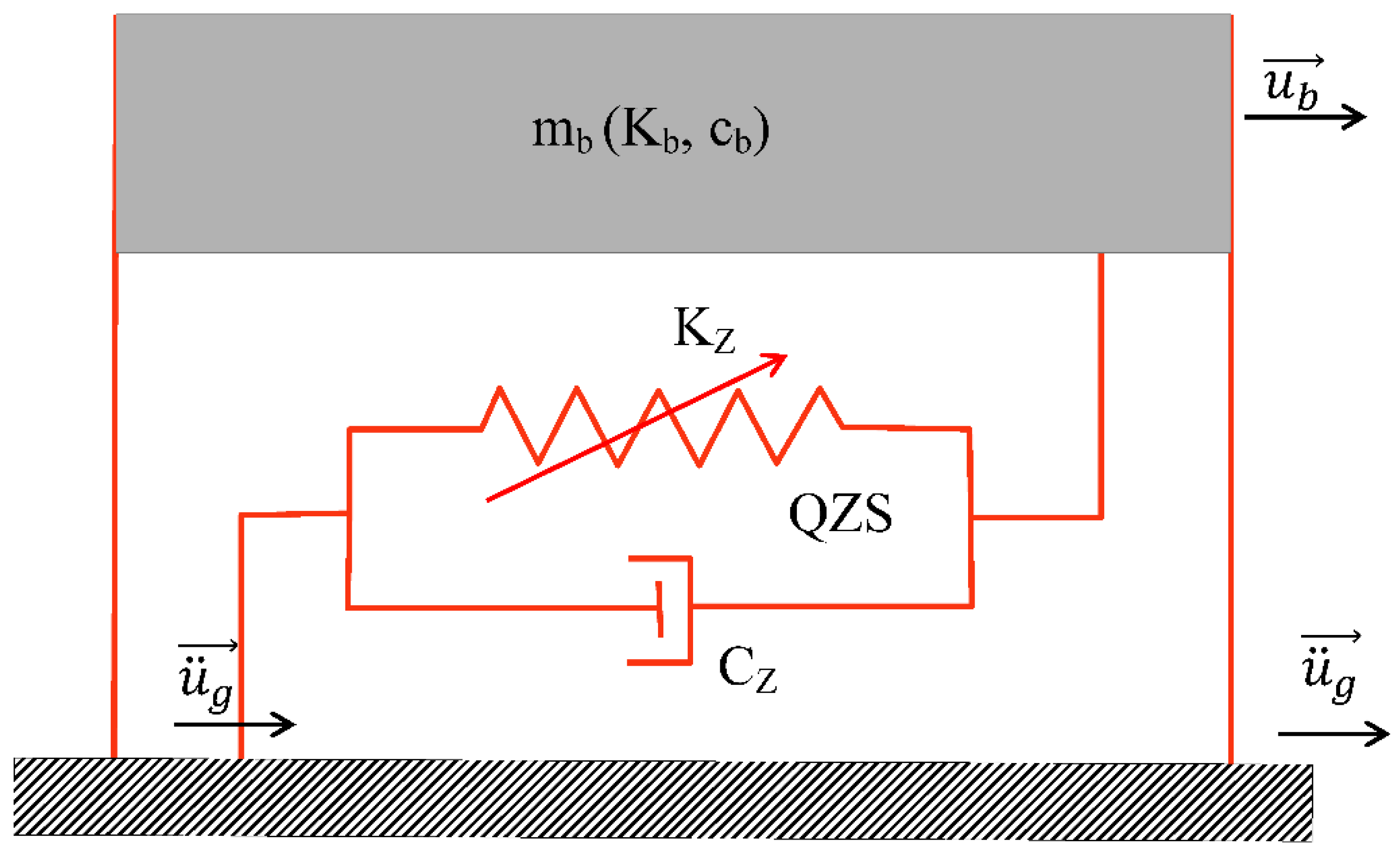
2.1. Equation of Motion for the Case of Quasi-Zero Stiffness

Figure 1 shows a QZS-isolated structure subjected to a horizontal external excitation ( u ¨ g ) and whose response u b is determined from Equation (1).
P b a s e + R s o l + F a r m o + T e l o n + F z = m b a b
where:
  • P b a s e : the weight of the base;
  • R s o l : the reaction of the ground due to the load of the building;
  • F a r m o : the inherent damping force of the base conferred on it by the various materials of which it is made;
  • F z : the force of the non-linear elastic damper;
  • T e l o n : the elongation force of the structure imparted by the steel;
  • a b : the acceleration felt at the base (foundation);
  • mb: the mass of the base above the isolation system;
  • γ : the damping ratio of the non-linear damper to that of the structure;
  • k : the ratio of the stiffness of the damper structure to that of the structure.
By replacing each term in Equation (1) by its value, Equation (2) is obtained.
c b u ˙ b + k z u b 3 + c z u ˙ b + k b u b = m b . u ¨ b + u ¨ g
Expanding Equation (2) gives Equation (3)
u ¨ b + 2 ε b ω b u ˙ b + 2 ε b ω b γ u ˙ b + k ω b 2 u b 3 + ω b 2 u b = u ¨ g
where:
ε b = c b 2 m b ω b
ω b = k b m b
γ = c z c b
k = k z k b
The dimensionless form of the equation of motion is obtained from the time scale Equation (8)
τ = ω b t
and taking the excitation signal, Equation (9)
u ¨ g = a 0 X 0 ( τ )
where a 0 is the seismic intensity scale, which has the same dimension as the signal acceleration, and X 0 ( τ ) is the time non-dimensional function describing the excitation signal history.
By integrating Equations (4)–(9), Equation (10) is obtained
φ ¨ b + 2 1 + γ ε b φ ˙ b + φ b + k a 0 2 ω b 4 φ b 3 = X 0 ( τ )
where:
φ b = ω b 2 a 0 u b
For the scaled function X 0 ( τ ) harmonic, Equation (12)
X 0 ( τ ) = X 0 sin β τ +
and using the harmonic balance [28], the response of the structure will be expressed as Equation (13)
φ b = X b sin   β τ
with β the scaled pulsation of the signal used in Equation (14)
X b β 2 sin β τ + 2 ε b ( 1 + γ ) X b β cos β τ + k a 0 2 ω b 4 X b sin β τ 3 + X b sin β τ = X g sin β τ +
However, from Equations (15) and (16)
sin β τ 3 = 3 4 sin β τ 1 4 cos 3 β τ
sin   β τ + = sin β τ cos c o s β τ s i n
And neglecting the terms in sin (3(βτ)) [18,29,30,31,32,33,34], Equation (14) becomes Equation (17).
X b β 2 sin β τ + 2 ε b ( 1 + γ ) X b β cos β τ + 3 4 k a 0 2 ω b 4 X b 3 sin β τ + X b sin β τ = X g ( sin β τ cos c o s β τ s i n )
From Equation (17), we can deduce Equations (18) and (19);
X b β 2 + 3 4 k a 0 2 ω b 4 X b 3 + X b = X g cos
2 ε b ( 1 + γ ) X b β = X g s i n
Squaring Equations (18) and (19) and adding them together gives Equation (20):
9 16 k 2 a 0 4 ω b 8 X b 6 + 3 2 k ( 1 β 2 ) a 0 2 ω b 4 X b 4 + ( ( 1 β 2 ) 2 + 4 ε b 2 β 2 ( 1 + γ ) 2 ) X b 2 X g 2 = 0
After posing Equation (21),
ε = εb (1 + γ)
Equation (20) becomes Equation (22)
9 16 k 2 a 0 4 ω b 8 X b 6 + 3 2 k ( 1 β 2 ) a 0 2 ω b 4 X b 4 + ( 1 β 2 ) 2 + 4 β 2 ε 2 X b 2 X g 2 = 0

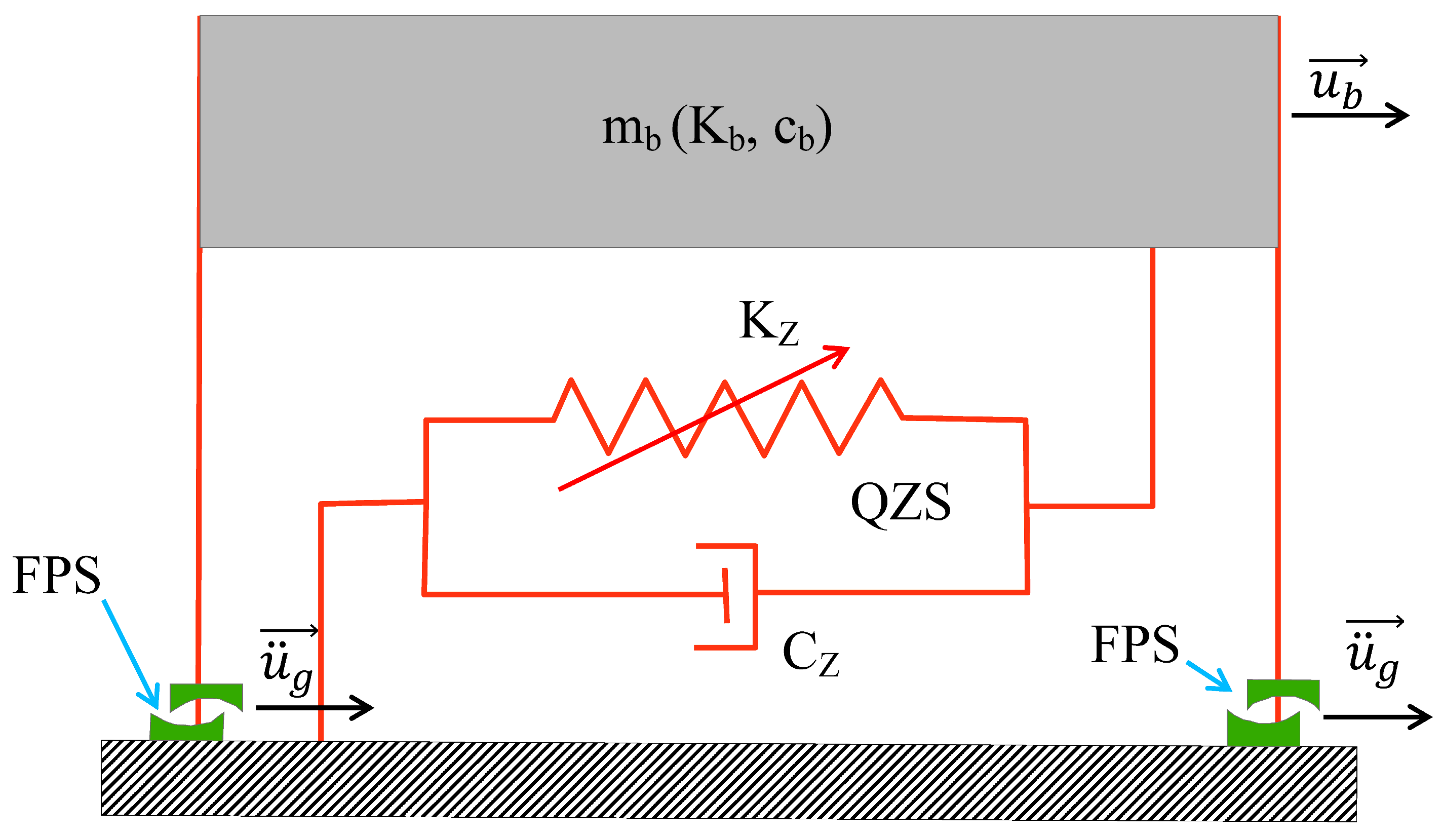
2.2. Equation of Motion for the Case of Quasi-Zero Stiffness Coupled to the FPS

Figure 2 shows the structure isolated by the coupling of the QZS and the FPS. The equation of motion governing the behavior of this structure under external excitation is determined from Equation (23).
P b a s e + R s o l + F a r m o + T e l o n + F z + F b = m b a b
where:
  • P b a s e : the weight of the base;
  • R s o l : the reaction of the ground due to the load of the building
  • F a r m o : the inherent damping force of the base conferred on it by the various materials from which it is made;
  • F z : the force of the non-linear elastic damper;
  • F b : the force of the double FPS;
  • T e l o n : the elongation force of the structure conferred on it by the steel;
  • a b : the acceleration felt at the base (foundation);
  • mb: the mass of the base above the isolation system;
  • γ : the ratio of the damping coefficient of the non-linear damper to that of the structure;
  • k : the ratio of the stiffness of the damper to that of the structure;
  • μ ( u ˙ b ) : the sliding friction coefficient;
  • k b : the stiffness constant of the structure;
  • k z : the stiffness constant of the non-linear damper;
  • f m a x : the maximum value of the coefficient of friction.
By replacing each term in Equation (23) with its value, Equation (24) is obtained.
u ¨ b + 1 m b c b u ˙ b + k z u b 3 + c z u ˙ b + 1 m b . k b u b + μ ( u ˙ b ) g Z ( t ) = u ¨ g
From Equation (24) we deduce Equation (25):
u ¨ b + 2 ε b ω b u ˙ b + 2 ε b ω b γ u ˙ b + k ω b 2 u b 3 + ω b 2 u b + μ ( u ˙ b ) g Z ( t ) = u ¨ g
where ε b , ω b , γ , and k are defined by Equations (4)–(7).
Writing Equations (26) and (27)
Z ( t ) = sign   ( u ˙ b )
μ u ˙ b = f m a x
and using the principle of Equation (3), Equation (28) is obtained from Equation (25) as follows:
φ ¨ b + 2 1 + γ ε b φ ˙ b + φ b + k a 0 2 ω b 4 φ b 3 + g f m a x s i g n ( φ ˙ b ) = X 0 ( τ )
Assuming harmonic seismic excitation, Equation (29)
  X 0 ( τ ) = X g sin β τ +
the response of the structure, Equation (31) will be expressed as [28]:
φ b = X b sin   β τ
X b β 2 sin β τ + 2 ε b ω b X b β cos β τ + 2 γ ω b X b β cos β τ + k ω b 2 X b sin β τ 3 + ω b 2 X b sin β τ + f m a x s i g n ( X b β cos β τ ) = X g sin β τ +
According to Equation (32)
s g n X b β cos β τ = 4 π β c o s ( β τ )
And neglecting the terms in sin   3 β τ , Equation (31) becomes Equation (33)
X b β 2 sin β τ + 2 ε b ω b X b β cos β τ + 2 ε b ω b γ X b β cos β τ + 3 4 k ω b 2 X b 3 sin β τ + ω b 2 X b sin β τ + 4 π f m a x β c o s ( β τ ) = X g ( sin β τ cos + c o s β τ s i n )
From Equation (33) we obtain Equations (34) and (35):
( 1 β 2 ) X b + 3 4 k a 0 2 ω b 4 X b 3 = X g cos
2 ε b ( 1 + γ ) X b β + 4 π f m a x β = X g s i n
Squaring Equations (34) and (35) and adding them together gives Equation (36)
9 16 k 2 a 0 4 ω b 8 X b 6 + 3 2 k ( 1 β 2 ) a 0 2 ω b 4 X b 4 + ( ( 1 β 2 ) 2 + 4 ε 2 β 2 ) X b 2 + 16 π ε X b β 2 f m a x + 16 π 2 f m a x 2 β 2 = X g 2
where ε is given in Equation (21).

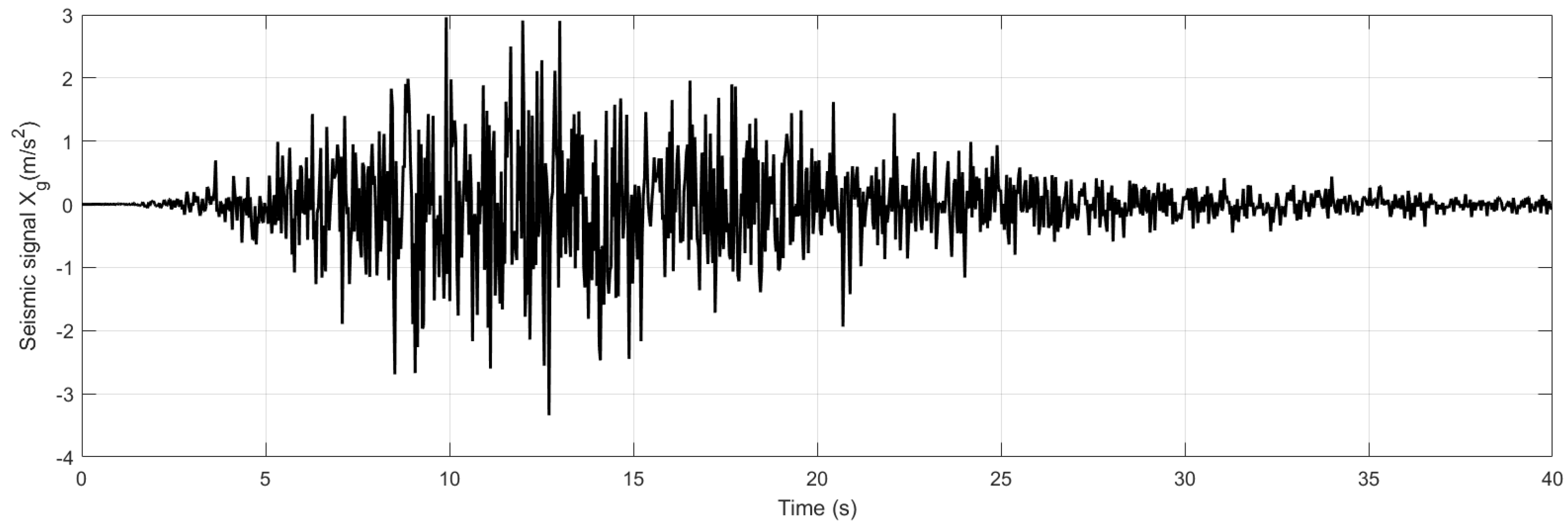
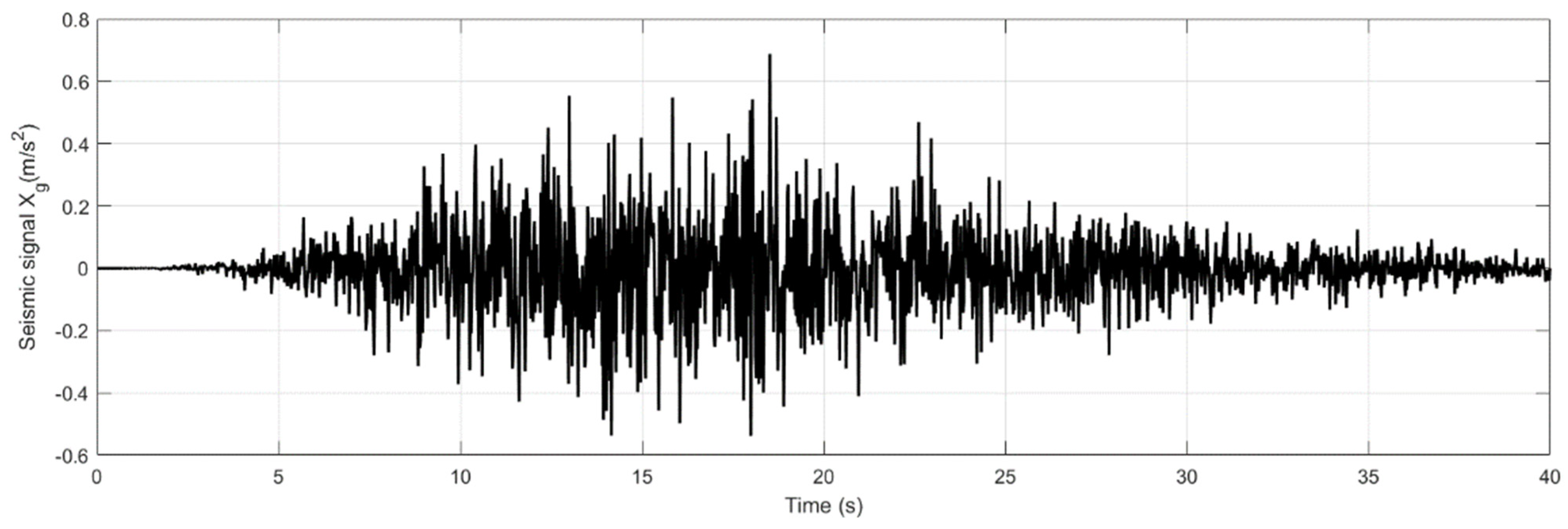
2.3. Case of Stochastic Excitation

In this case, the seismic loading ( u ¨ g ) is represented as random sequences of white Gaussian noise, adjusted by filtering and time modulation of varying intensity, in the context of spectral density analysis. The filter characteristics determine the frequency distribution of these random stresses and are adjusted to correspond to rigid, intermediate, or loose soil conditions, as appropriate. For this purpose, the Kanai–Tajimi filter modified by Clough and Penzien (Equations (37) and (38)) is used to model the different soil types.
S u ¨ g ( β ) = β 4 + 4 ε g 2 ω g 2 β 2 ( ω g 2 β 2 ) 2 + 4 ε g 2 ω g 2 β 2 β 4 ( ω f 2 β 2 ) 2 + 4 ε f 2 ω f 2 ω 2 S w
S w = 0.141 ε g ω g 1 + 4 ε g 2 u ¨ g 0 2
S w represents the spectral level of white noise linked to the maximum acceleration of the ground and u ¨ g 0 is the peak ground acceleration (PGA). ε g , ω g , ε f , and ω f are the filter parameters [35,36].
According to [37,38,39], we assume that the maximum value of the recorded ground acceleration oscillates between 0.4 g and 0.6 g.

3. Results and Discussion

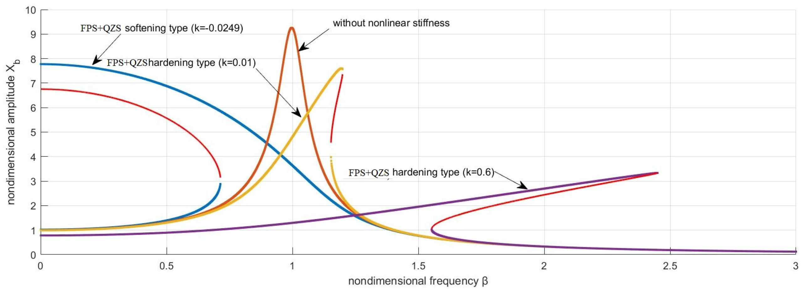
3.1. Amplitude–Frequency Response in the Case of a Harmonic Signal

Figure 3 shows the amplitude response of the non-isolated system isolated by the QZS according to its various characteristics as a function of the scaled frequency for a total system damping of 5%. In the case of a system isolated by a QZS with a softening stiffness (k = −0.0249), the amplitude curves slope as the frequency increases; in other words, the resonance frequency is inversely proportional to the amplitude of the oscillations. In contrast, for the system isolated by a rigid QZS (k = 0.01000 and k = 0.6000), the amplitude curves slope to the left, from which we deduce that the responses are weak at high resonance frequencies.
The amplitude–frequency responses of the system isolated by an FPS and by the QZS–FPS coupling are shown in Figure 4 for ε = 0.025. The slope of the amplitude–frequency response curves in Figure 4 shows the persistence of the QZS non-linearity despite the QZS–FPS coupling. In addition, the maximum amplitudes of the responses of the structure for the case of soft–stiff QZS coupling with the FPS are greater than those of the structure isolated only with an FPS. This is quite the opposite of those where the structure is isolated by a rigid QZS coupling and an FPS, which are the lowest as the stiffness increases.

3.2. Amplitude Response for the Case of a Stochastic Signal

The various seismic signals were derived from Equation (17).

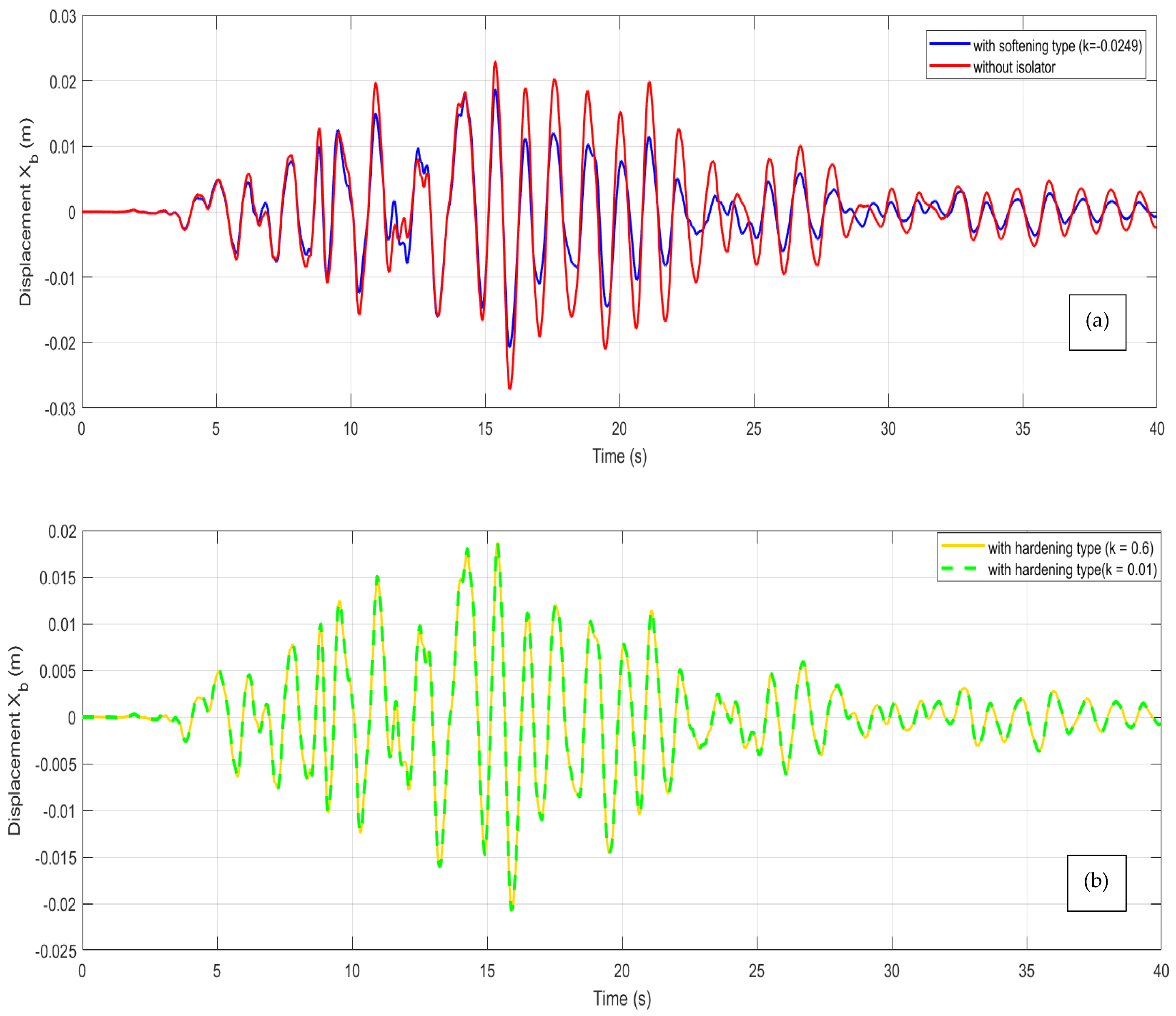
3.2.1. Case of Soft Ground

Figure 5 shows the time evolution of the seismic signal Xg, modeled according to the Kanai–Tajimi spectrum modified by Clough and Penzien. The signal shows amplitude variations between −4 m/s2 and 3 m/s2 over a period of 40 s. The oscillations observed are characterized by acceleration and deceleration phases, which are essential for analyzing the dynamic response of structures.
The response of the structure to this signal is shown in Figure 6 for the different cases of isolation (QZS and QZS–FPS coupling). For an uninsulated structure, the amplitudes vary between −0.028 m and 0.026 m, while in the case of low stiffness isolation, the amplitudes of the oscillations vary between −0.021 m and 0.019 m. The negative and positive displacements show that the building oscillates around its equilibrium position. Furthermore, the amplitudes of the oscillations in the case of rigid stiffness isolation vary between −0.021 m and 0.019 m. In other words, the amplitudes of the oscillations in the case of isolation with a soft stiffness are smaller than those of isolation with a rigid stiffness.
The response of the structure to the seismic signal in a soft ground environment is shown in Figure 7. The amplitude of the oscillations for the case of a QZS coupling with soft-stiffness FPS varies between −0.0052 m and 0.0071 m while that isolated by the friction pendulum alone varies between −0.0094 m and 0.0065 m. Conversely, Figure 7b shows that for a high-stiffness damper, the amplitude curve varies between −0.0056 m and 0.0069 m.

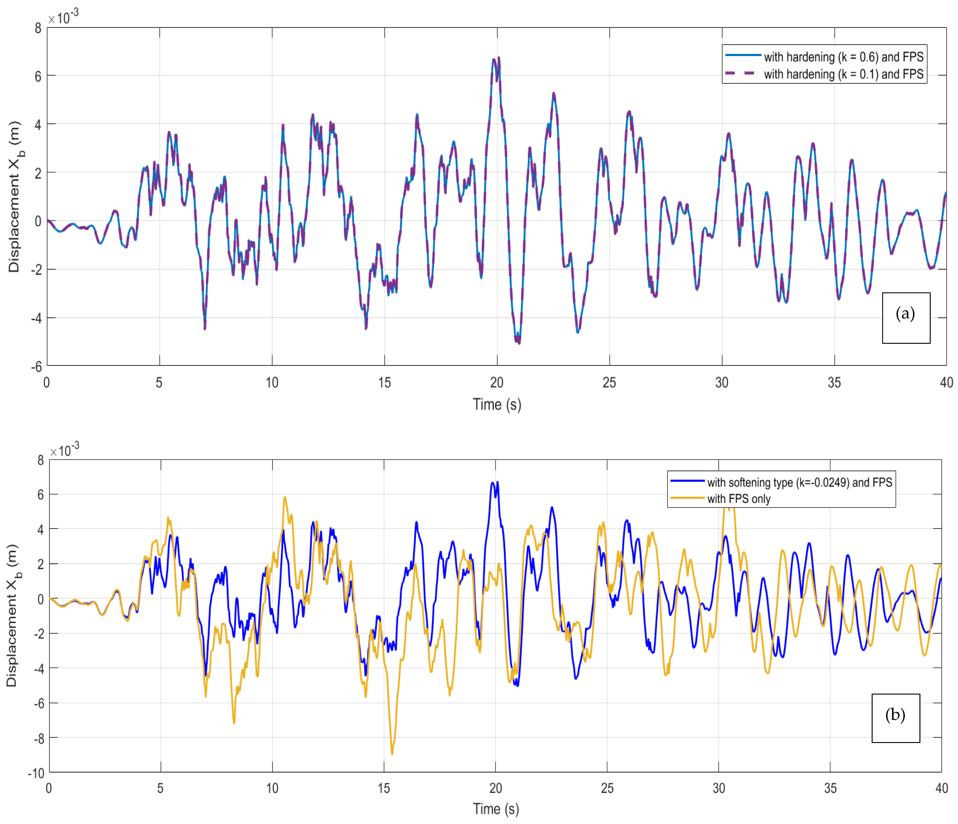
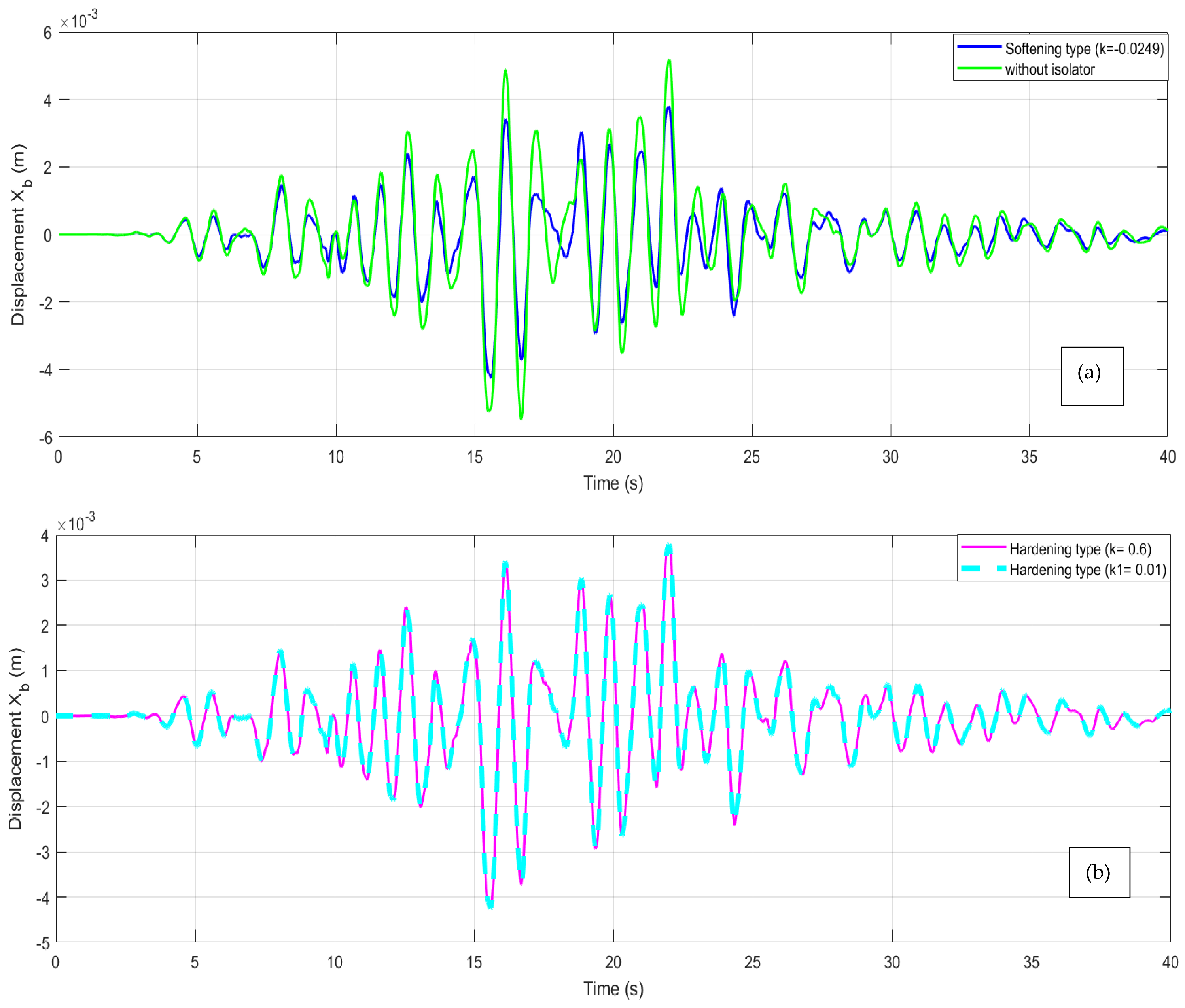
3.2.2. Case of Hard Ground

Figure 8 shows the temporal evolution of the Xg seismic signal in a rigid soil environment.
Figure 9 shows the time trace of the response of the structure. For the same seismic signal, the amplitudes are constant to a few decimal places in the case of a rigid QZS, whereas the amplitudes of the oscillations decrease in the case of a soft QZS.
Figure 10 shows the response of the structure under different types of isolation. The blue curve in Figure 10a shows the evolution of the dependent variable (for example, performance or displacement) in a system where a softening with a coefficient k = −0.0249 is applied, in conjunction with FPS management, whereas the green curve shows the evolution of the same dependent variable in a system where only FPS management is applied. As for Figure 10b, the interrupted curve represents the response of the structure isolated by the QZS–FPS coupling with rigid stiffness k = 0.6 and the solid line represents the QZS–FPS coupling with rigid stiffness k = 0.01. Figure 6 shows that the structure isolated by the soft–stiff QZS–FPS coupling has a lower amplitude than that isolated by the QZS and the stiff QZS–FPS coupling.

3.3. Discussion

3.3.1. Case of a Harmonic Signal

Figure 3 and Figure 4 show the amplitude–frequency response of a structure that was initially uninsulated, then isolated by the QZS and by the QZS–FPS coupling at different stiffnesses. The curves observed in Figure 4 show the importance of the non-linearity of the QZS compared with that of the friction pendulum [16,35]. The response of the soft–stiff QZS–FPS system to a harmonic pulse showed amplitudes of the order of eight times that of the excitation pulse for low frequencies and amplitudes close to 0 for high frequencies. In the case of the QZS–FPS system with rigid stiffness, the oscillations have amplitudes of the order of 0.9 and 3.5 times those of the harmonic signal, but lower than those of [40,41], showing that the FPS plays a major role not only in the performance but also in the stabilization of the system and that the QZS–FPS system with soft stiffness does not react very effectively to low-frequency harmonic signals, unlike that with rigid stiffness.

3.3.2. Case of a Stochastic Signal

The effectiveness of the proposed solution is illustrated by a decrease in oscillation amplitudes of around 30% on soft and hard ground in Figure 7 and Figure 10. In addition, Figure 7 and Figure 10 show that the QZS–FPS coupling with soft stiffness is the most effective under different types of soil, probably due to the performance of the QZS with soft stiffness, as shown in Figure 6a and [4,42]. Moreover, on both hard and soft ground, the new QZS–FPS system causes structures to vibrate horizontally with maximum amplitudes of the order of 0.003 m and 0.007 m, respectively. Finally, when compared with pre-existing hybrid dampers (Table 1), the QZS–FPS system outperformed NS–TMD, FPSIS, NS–FPS, and FPS–TMD.

4. Conclusions

Non-linear isolation devices are an emerging area of research and have, due to their promising potential, attracted considerable attention in the scientific community. The aim of this study was to evaluate the effect of horizontal ground excitation on the response of a structure isolated by a coupled system consisting of a non-linear damper (QZS) and a friction pendulum (FPS), using harmonic signal and stochastic signal. Analysis of the response of the QZS–FPS system with soft and rigid stiffness reveals its remarkable ability to absorb harmonic pulses. However, the QZS–FPS system with soft stiffness does not respond very effectively to low-frequency harmonic signals, whereas the system with rigid stiffness does. This distinction underlines the importance of choosing the type of stiffness according to specific application requirements. The stochastic results show that on both hard and soft soils, the proposed QZS–FPS system causes structures to vibrate horizontally with maximum amplitudes of the order of 0.003 m and 0.007 m, respectively. So, the QZS–FPS coupling can be more effective than all other isolators for horizontal ground excitation. To improve on the existing work, another study with several degrees of freedom could be envisaged.

Author Contributions

Conceptualization, R.K.W.W. and P.N.N.; methodology, R.K.W.W., S.C.T., E.F.K.P., B.P.G.P., A.M.P.N., E.M.D. and P.N.N.; software, R.K.W.W., S.C.T., E.F.K.P., B.P.G.P., A.M.P.N., E.M.D. and P.N.N.; validation, R.K.W.W., S.C.T., E.F.K.P., B.P.G.P., A.M.P.N., E.M.D. and P.N.N.; formal analysis, R.K.W.W., A.M.P.N. and P.N.N.; investigation, R.K.W.W., A.M.P.N. and P.N.N.; data curation, R.K.W.W., S.C.T., E.F.K.P., B.P.G.P., A.M.P.N., E.M.D. and P.N.N.; validation, R.K.W.W., S.C.T., E.F.K.P., B.P.G.P., A.M.P.N., E.M.D. and P.N.N.; writing—original draft preparation, R.K.W.W., S.C.T., E.F.K.P., B.P.G.P., A.M.P.N., E.M.D. and P.N.N.; validation, R.K.W.W., S.C.T., E.F.K.P., B.P.G.P., A.M.P.N., E.M.D. and P.N.N.; writing—review and editing, R.K.W.W., S.C.T., E.F.K.P., B.P.G.P., A.M.P.N., E.M.D. and P.N.N.; validation, R.K.W.W., S.C.T., E.F.K.P., B.P.G.P., A.M.P.N., E.M.D. and P.N.N.; visualization, R.K.W.W. and E.M.D.; supervision, P.N.N.; project administration, E.M.D. and P.N.N.; All authors have read and agreed to the published version of the manuscript.

Funding

This research received no external funding.

Data Availability Statement

The data presented in this study are available on request from the corresponding author.

Acknowledgments

The authors would like to thank the editors, the three anonymous reviewers for their professional comments to improve the manuscript and also Ngo Nouck Hélène, Nguentchue Rose, Meli’i Jorelle Larissa, Department of Physics, University of Yaounde I, Mbouombouo Ngapouth Ibrahim, Department of Physics, University of Yaounde I, Marthe Ariane Mbond Gweth, National Advanced School of Public Work, Yaounde Cameroon, Fotsa Tematio Patrice, Civil Engineer at UCB S.A. Cameroon and Nongni Tsopmo F. for the facilitation.

Conflicts of Interest

The authors declare no conflicts of interest.

References

  1. Snowdon, J.C. Vibration isolation: Use and characterization. J. Acoust. Soc. Am. 1979, 66, 1245–1274. [Google Scholar] [CrossRef]
  2. Alabuzhev, P.M. Vibration Protection and Measuring Systems with Quasi-Zero Stiffness; CRC Press: Boca Raton, FL, USA, 1989. [Google Scholar]
  3. Gudainiyan, J.; Gupta, P.K. A comparative study on the response of the L-shaped base isolated multi-storey building to near and far field earthquake ground motion. Forces Mech. 2023, 11, 100191. [Google Scholar] [CrossRef]
  4. Hui, Y.; Zhou, T.; Liu, J.; Jia, H.; Zhang, S. Seismic response study of multi-span continuous beam bridges near faults considering permanent displacement attenuation effects. Structures 2024, 69, 107516. [Google Scholar] [CrossRef]
  5. Kang, X.; Li, S.; Yan, C.; Jiang, X.; Hou, H.; Fan, Z.; Mao, D.; Huang, Q. Enhancing the seismic performance of adjacent building structures based on TVMD and NSAD. Buildings 2023, 13, 2049. [Google Scholar] [CrossRef]
  6. Pisal, A.Y.; Jangid, R.S. Dynamic response of structure with tuned mass friction damper. Int. J. Adv. Struct. 2016, 8, 363–377. [Google Scholar] [CrossRef]
  7. Yang, Y.; Zhou, Z.; Wang, X.; Zhang, X.; Wang, Z. 2.5-dimension soil seismic response to oblique incident waves based on exact free-field solution. Front. Struct. Civ. Eng. 2024, 18, 216–235. [Google Scholar] [CrossRef]
  8. Hassan, A.L.; Billah, A.M. Influence of ground motion duration and isolation bearings on the seismic response of base-isolated bridges. Eng. Struct. 2020, 222, 111129. [Google Scholar] [CrossRef]
  9. Habieb, A.B.; Valente, M.; Milani, G. Implementation of a simple novel Abaqus user element to predict the behavior of unbonded fiber reinforced elastomeric isolators in macro-scale computations. Bull. Earthq. Eng. 2019, 17, 2741–2766. [Google Scholar] [CrossRef]
  10. Zhao, Z.; Wang, Y.; Chen, Q.; Qiang, H.; Hong, N. Enhanced seismic isolation and energy dissipation approach for the aboveground negative-stiffness-based isolated structure with an underground structure. Tunn. Undergr. Space Technol. 2023, 134, 105019. [Google Scholar] [CrossRef]
  11. Li, H.; Li, Y.; Li, J. Negative stiffness devices for vibration isolation applications: A review. Adv. Struct. Eng. 2020, 23, 1739–1755. [Google Scholar] [CrossRef]
  12. Wu, X.; Wang, J.; Zhou, J. Seismic performance analysis of a connected multitower structure with FPS and viscous damper. Shock. Vib. 2018, 2018, 1865761. [Google Scholar] [CrossRef]
  13. Xiong, M.; Huang, Y. Novel perspective of seismic performance-based evaluation and design for resilient and sustainable slope engineering. Eng. Geol. 2019, 262, 105356. [Google Scholar] [CrossRef]
  14. Zhang, Z.; Bi, K.; Hao, H.; Sheng, P.; Feng, L.; Xiao, D. Development of a novel deformation-amplified shape memory alloy-friction damper for mitigating seismic responses of RC frame buildings. Eng. Struct. 2020, 216, 110751. [Google Scholar] [CrossRef]
  15. Chen, B.; Qiu, Y.; Xiong, J.; Liu, Y.; Xu, Y. Seismic performance and optimization of a novel partial seismic isolation system for frame structures. Buildings 2022, 12, 876. [Google Scholar] [CrossRef]
  16. Chaoran, L.; Zhang, W.; Yu, K.; Tao, L.; Yan, Z. Quasi-zero-stiffness vibration isolation: Designs, improvements and applications. Eng. Struct. 2024, 301, 117282. [Google Scholar]
  17. Jin, Z.; Chen, K.; He, J. Improving vehicle’s seismic safety by equipping railway bridges with FPB and misalignment control device. Adv. Bridge Eng. 2022, 3, 4. [Google Scholar] [CrossRef]
  18. Abolfathi, A. Can a nonlinear quasi-zero-stiffness spring improve the ride quality of a vehicle. Veh. Syst. Dyn. 2024, 62, 330–346. [Google Scholar] [CrossRef]
  19. Naeim, F.; Kelly, J.M. Design of Seismic Isolated Structures: From Theory to Practice; John Wiley & Sons: Hoboken, NJ, USA, 1999. [Google Scholar]
  20. Wang, M.; Sun, F.F.; Yang, J.Q.; Nagarajaiah, S. Seismic protection of SDOF systems with a negative stiffness amplifying damper. Eng. Struct. 2019, 190, 128–141. [Google Scholar] [CrossRef]
  21. Chen, X.; Wu, P.; Li, C. Seismic performance assessment of base-isolated tall pier bridges using friction pendulum bearings achieving resilient design. Structures 2022, 38, 618–629. [Google Scholar] [CrossRef]
  22. Saboo, A.; Khan, M.; Kumar, M.; Sajish, S.D. Influence of seismic isolation on the earthquake response of internal components in a fast reactor. Nucl. Eng. Des. 2023, 413, 112522. [Google Scholar] [CrossRef]
  23. Du, Y.; Han, B.; Hong, N. Dynamic response and failure modes of base-isolated frame structures subjected to earthquakes under dynamic bearing removal scenarios. J. Build. Eng. 2023, 72, 106556. [Google Scholar] [CrossRef]
  24. Castaldo, P.; Palazzo, B.; Della, P.V. Seismic reliability of base-isolated structures with friction pendulum bearings. Eng. Struct. 2015, 95, 80–93. [Google Scholar] [CrossRef]
  25. Shaodong, J.; Ma, R.; Bi, K.; Li, H.; Du, X. Negative stiffness enhanced TMD for seismic response mitigation of bridges isolated with friction pendulum system (FPS). Eng. Struct. 2025, 331, 119978. [Google Scholar]
  26. Zhipeng, Z.; Yuanchen, T.; Hong, N.; Chen, Q.; Yongfeng, D. Interaction-performance-driven design of negative-stiffness friction pendulum systems for aboveground structure–connected underground structure–soil system with ground motion effects. J. Build. Eng. 2024, 88, 108970. [Google Scholar]
  27. Zhipeng, Z.; Zhang, R.; Jiang, Y.; Pan, C. Seismic response mitigation of structures with a friction pendulum inerter system. Eng. Struct. 2019, 193, 110–120. [Google Scholar]
  28. Dal Bo, L.; Turco, E.; Gardonio, P. Electromagnetic and piezoelectric time-varying units for the control of flexural vibrations of thin-walled structures. Mech. Adv. Mater. Struct. 2023, 30, 1083–1094. [Google Scholar] [CrossRef]
  29. Stoker, J.J. Non-Linear Vibrations in Mechanical and Electrical Systems; John Wiley & Sons: New York, NY, USA, 1992. [Google Scholar]
  30. Nayfeh, A.H.; Mook, D.T. Non-Linear Oscillations; Wiley—Interscience: New York, NY, USA, 1979. [Google Scholar]
  31. Dominic, D.W.; Jordan, W.; Smith, P. Non-Linear Ordinary Differential Equations: An Introduction for Scientists and Engineers; Oxford University Press: Oxford, UK, 2007. [Google Scholar]
  32. Hayashi, C. Non-Linear Oscillations in Physical Systems; McGraw-Hill: New York, NY, USA, 1964. [Google Scholar]
  33. Dal, B.L.; Gardonio, P.; Battistella, N.; Turco, E. Non-linear Isolator for Vibration and Force Transmission Control of Unbalanced Rotating Machines. J. Vib. Eng. Technol. 2023, 11, 1741–1764. [Google Scholar] [CrossRef]
  34. Clough, R.W.; Penzien, J. Dynamics of Structures, 2nd ed.; Mc Graw-Hill: New York, NY, USA, 1993. [Google Scholar]
  35. Huo, Z.Y.; Khalique, C.M. Stochastic Seismic Analysis of Structures with Nonlinear Eddy Current Dampers. J. Low Freq. Noise Vib. Act. Control 2023, 42, 69–79. [Google Scholar] [CrossRef]
  36. Karim, K.R.; Yamazaki, F. Effect of Earthquake Ground Motions on Fragility Curves of Highway Bridge Piers Based on Numerical Simulation. Earthq. Eng. Struct. Dyn. 2001, 30, 1839–1856. [Google Scholar] [CrossRef]
  37. Ambraseys, N.N.; Douglas, J. Magnitude Calibration of North Indian Earthquakes. Geophys. J. Int. 2004, 159, 165–206. [Google Scholar] [CrossRef]
  38. Zentner, I.; Poirion, F. Enrichment of Seismic Ground Motion Databases Using Karhunen–Loève Expansion. Earthq. Eng. Struct. Dyn. 2012, 41, 1945–1957. [Google Scholar] [CrossRef]
  39. Zhaozhao, M.; Ruiping, Z.; Qingchao, Y. Recent Advances in Quasi-Zero Stiffness Vibration Isolation Systems: An Overview and Future Possibilities. Machines 2022, 10, 813. [Google Scholar] [CrossRef]
  40. Sui, G.; Zhang, X.; Hou, S.; Shan, X.; Hou, W.; Li, J. Quasi-Zero Stiffness Isolator Suitable for Low-Frequency Vibration. Machines 2023, 11, 512. [Google Scholar] [CrossRef]
  41. Brennan, M.J.; Kovacic, I.; Carrella, A.; Waters, T.P. On the jump-up and jump-down frequencies of the Duffing oscillator. J. Sound Vib. 2008, 318, 1250–1261. [Google Scholar] [CrossRef]
  42. Bhowmik, K.; Debnath, N. On Stochastic Design of Negative Stiffness Integrated Tuned Mass Damper (NS-TMD). J. Vib. Eng. Technol. 2021, 9, 2197–2211. [Google Scholar] [CrossRef]
Figure 1. Structure isolated by QZS under horizontal excitation.
Buildings 15 01498 g001
Figure 2. Structure isolated by QZS–FPS coupling under horizontal excitation.
Buildings 15 01498 g002
Figure 3. Amplitude–frequency response, case of QZS.
Buildings 15 01498 g003
Figure 4. Amplitude–frequency response, case of QZS–friction pendulum coupling.
Buildings 15 01498 g004
Figure 5. Seismic signal for soft ground.
Buildings 15 01498 g005
Figure 6. Response of the structure on soft soil: (a) case of a non-isolated structure and isolated by a soft-stiffness QZS; (b) case of a structure isolated by a rigid-stiffness QZS (k = 0.01 and k = 0.6).
Buildings 15 01498 g006
Figure 7. Response of the structure to the seismic signal on soft soil: (a) case of a structure isolated by the soft-stiffness QZS-FPS coupling; (b) case of a structure isolated by the rigid-stiffness QZS–FPS coupling (k = 0.01 and k = 0.6).
Buildings 15 01498 g007
Figure 8. Seismic signal for hard ground.
Buildings 15 01498 g008
Figure 9. Response of the structure on hard ground: (a) case of a non-isolated structure isolated by the soft-stiffness QZS; (b) case of a structure isolated by the rigid-stiffness QZS (k = 0.01 and k = 0.6).
Buildings 15 01498 g009
Figure 10. Response of the isolated structure: (a) by the FPS and by the coupling (QZS with soft stiffness and FPS); (b) by the coupling QZS–FPS with rigid stiffnesses k = 0.6 and k = 0.01.
Buildings 15 01498 g010
Table 1. Comparison of the performance of hybrid systems proposed by various authors.
SystemsImprovementsReference
NS–TMDImproves the stability of a bridge previously equipped with FPS. Reduces vibration with a maximum output amplitude of 0.081 m.[25]
FPSISReduces vibrations with a maximum amplitude of 0.8 m.[27]
NS–FPSPresents an innovative solution to improve the seismic resilience of above-ground buildings and underground infrastructures (ASUS) by coupling negative stiffness and friction pendulum.[26]
FPS–TMDReduces vibration with a maximum amplitude of 0.1 m.[27]
Disclaimer/Publisher’s Note: The statements, opinions and data contained in all publications are solely those of the individual author(s) and contributor(s) and not of MDPI and/or the editor(s). MDPI and/or the editor(s) disclaim responsibility for any injury to people or property resulting from any ideas, methods, instructions or products referred to in the content.

