Article

Investigation of Hysteresis Effect in Torque Performance for a Magnetorheological Brake in Adaptive Knee Orthosis

Department of Vehicle Engineering, National Taipei University of Technology, Taipei 106, Taiwan
*
Author to whom correspondence should be addressed.
Actuators 2021, 10(10), 271; https://doi.org/10.3390/act10100271
Submission received: 31 August 2021 / Revised: 2 October 2021 / Accepted: 12 October 2021 / Published: 15 October 2021
(This article belongs to the Special Issue Actuators in Robotic Control)

Abstract

:
Semi-active knee orthosis (SAKO) is a kind of wearable lower-limb exoskeleton that uses actuators to support the regular biomechanical functions. It is much better than conventional knee orthosis (CKO) devices because of its high torque to volume ratio (TVR) and low mass. Magnetorheological (MR) brake is one of the smart actuators that can be used as an active resistance device in SAKO. It has advantages of fast response, low power consumption, and low vibration operation. This smart brake also has wide applications in the robotic and automotive industries. However, the electromagnetic setup in MR brakes has a hysteresis problem. This paper aims to turn this hysteresis problem into an advantage to save the power consumption of MR brake. Since the SAKO needs precise torque control, this research studied the hysteresis effect on the torque performance of MR brake. A less energy-consuming PWM actuation signal is proposed to activate the MR brake. The effects of frequency and duty cycle of PWM actuation signal on MR brake performance are also investigated. The electromagnetic (EM) and mechanical models of the MR brake were developed to simulate performance. Initial validation of these models is done by simulating the MR brake model with the DC actuation signal in finite element analysis software. For the final validation, the model simulation results are compared with experimental results. The factors affecting the steady torque and the response time of the MR brake are studied to find the optimal frequency and duty cycle for the applied PWM signal. This study revealed that the proposed new PWM actuation signal with a 5 kHz frequency and 60% duty cycle can power the MR brake to maintain steady torque. By turning hysteresis into an advantage, it saves 40% power consumption of MR brake compared to DC signal.

1. Introduction

Wearable robotic exoskeletons have been extensively researched in the past decade. They play a vital role in assisting patients with mobility problems [1]. Robotic exoskeletons are used in various joints of the body. The actuators of the exoskeleton can be designed and modified as per the location and mobility requirement of the body [2]. The mechanical design of the exoskeleton can have multiple degrees of freedom (DOF) depending on the type of joint and comfort. They are classified based on the type of actuator used [3]. The friction in the robotic exoskeletons is modeled to extend its use in stiffness applications [4].
As humans grow older their body loses muscular strength which limits their mobility. To help them regain regular biomechanical functions, exoskeletons have been designed. It consists of a wearable frame, actuators, sensors, and a controller. People with knee joint problems cannot have desired mobility. To help them walk naturally knee orthosis device is used (Shiao et al., 2017) [5]. It is a kind of exoskeleton with a similar design and used to support the lower limbs. Conventional knee orthosis (CKO) device assists the people facing problems with gait movement (Daniel S Pamungkas et al., 2019) [6]. However, it cannot completely provide natural free knee movement. Active knee orthosis (AKO) devices help patients to walk more naturally. Beyl et al. [7] introduced an adaptive knee orthosis device that uses an active electric motor. However, the drawbacks of AKO are its heavy mass, high power consumption, large volume, and high cost. It is used by people only with severe knee problems. Weinberg et al. [8] proposed an Electrorheological (ER) resistance-based SAKO device. On the other hand, its applications are limited due to the high ER voltage limit and high mass. Recently, Shiao et al. (2021) [9] introduced a SAKO device that uses a multilayer MR brake with high TVR, low mass, less volume.
MR brakes are promising smart devices in future prosthetic and knee applications. It provides variable torque and can be controlled with simple actuating signals such as pulse width modulation (PWM). The output torque of the MR brake is generally controlled by varying input current [10]. A controllable fluid which is filled inside an MR brake has a special feature such as changing its rheological behavior in the presence of the magnetic field. Such fluid is called magnetorheological fluid (MRF). It was discovered by J. Rainbow in late 1940′s. The viscosity of MR fluid can be controlled by the applied controllable magnetic field [11]. It is formed by mixing micron sized ferromagnetic particles with carrier fluid such as hydrocarbon oils and some additives. MR fluid can be operated in four modes: squeeze mode, pinch mode, direct-shear mode and valve mode [12]. MR brakes are designed to use the third mode. This mode opposes the relative motion between two surfaces. In the presence of a magnetic field, these particles form a chain structure in the direction of magnetic field [13]. It changes its state from low viscous fluid to a semi-solid substance. On the removal of external magnetic field MR fluid reverts to its original state in a few milliseconds.
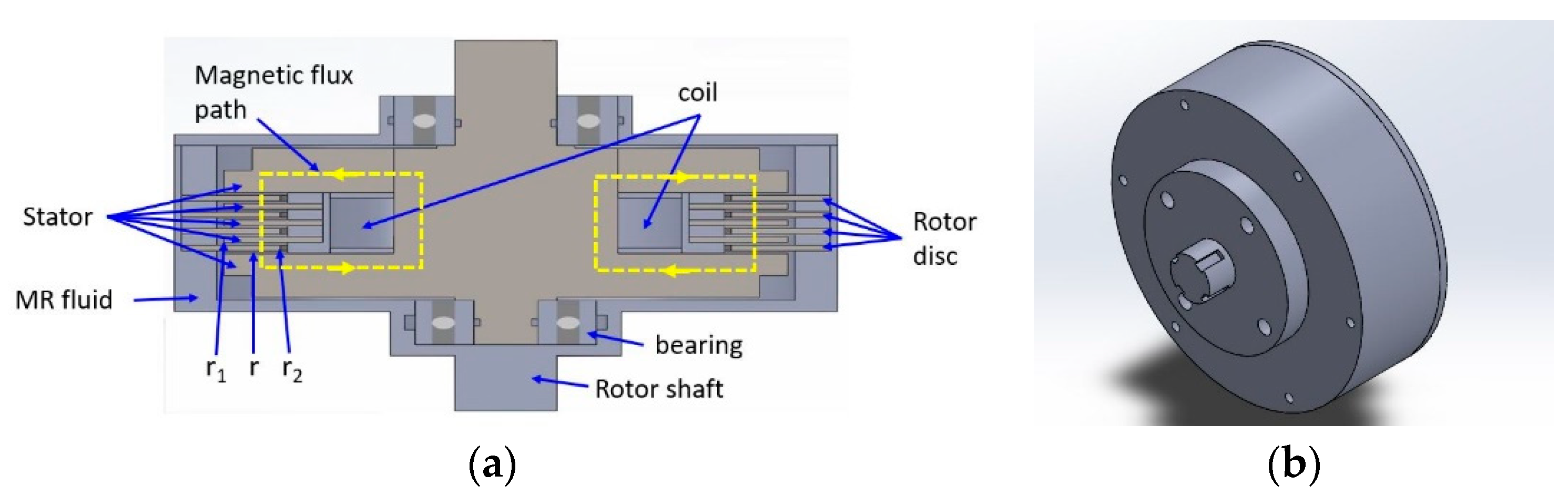
MR brake generally consists of an electromagnetic coil, rotating disc, and MR fluid. Whenever a current passes through the coil, it creates a magnetic field and the MR fluid state changes. This change results in more friction between the fluid and the rotating disc. The first commercial single-pole single-layer MR brake was designed by Lord company [14]. In later years, Wang improved the torque of the MR brake by developing a single-pole multilayer MR brake [15]. However, these designs did not improve the torque more effectively. In recent years, Shiao introduced a multipole multilayer MR brake which effectively used the magnetic field to obtain high torque [16].
A challenging problem in this application issue is hysteresis which is one of the major topics investigated in this MR field. The hysteresis effect causes nonlinearity in the system. This problem is usually overcome by modeling hysteresis. From the literature survey, it is known that many theories are proposed in the past to put the hysteresis effect in ferromagnetic materials in dynamic models. In 1986, Jiles and Atherton proposed a model on the hysteresis effect in ferromagnetic materials based on domain wall motion [17,18]. It becomes one of the most widely used hysteresis models. The nonlinear behavior in the performance of MR devices is mainly due to the hysteresis effect. Li and Gong numerically simulated the Jiles Atherton model in Matlab/Simulink to describe the nonlinearity between the magnetic field intensity and the input current to the MR brake [19].
Other studies used different approaches to eliminate the hysteresis in MR devices [20,21,22]. To the best of our knowledge, most of the studies in past focused only on hysteresis elimination and its effect on the torque of MR brake. Most of these studies used the DC voltage control method to vary the corresponding current level and the torque of the MR brake. This method requires a continuous power supply to MR brake. Therefore, it consumes more power. A literature study found that driving the electromagnetic coils with the PWM signal improves the efficiency of coil power consumption [23]. Thus, optimal design of magnetorheological devices can be achieved by the mechanical structure improvement and the design parameters of electrical and magnetic circuits [24]. Besides this, none of the studies investigations can turn the hysteresis problem into an advantage in MR brakes. Hysteresis in some cases made useful for the storage of data in the hard disk.
In this paper, the hysteresis effect on torque performance of MR brake is investigated under PWM actuation signal. PWM signal drives an MR brake by chopping the input voltage and current at high frequencies. The coil inside an MR brake has self-inductance and the ferromagnetic core has a hysteresis effect. By making use of these two effects and selecting PWM as an actuation signal, the power consumption of the MR brake can be significantly reduced. In addition to this, the effect of frequency and duty cycle on the torque performance of MR brake is also studied. Investigation in this research revealed that the response time of MR brake depends on parameters such as time constant (Tc) and reluctance (S) in the electrical and magnetic circuit. The MR fluid filled inside this MR brake is MRF 140-CG which was manufactured by Lord company [25]. The response time of the fluid is very less compared to the RL electrical circuit inside the MR brake.

2. Hysteresis Effect on MR Brake

Hysteresis is a common phenomenon observed in most areas of engineering. Similarly, it also exists in MR devices and causes limitations in applications of MR devices. Hysteresis in MR brakes majorly exists in ferromagnetic material of the core. It causes nonlinearity in torque control of MR brake. In addition, B-H curve of MR fluid demonstrates little to no hysteresis. This effect is due to the use of magnetically soft properties of the iron used as particles in these fluids and the mobility of particles [26]. This study aimed to investigate this hysteresis effect under the PWM actuation signal.
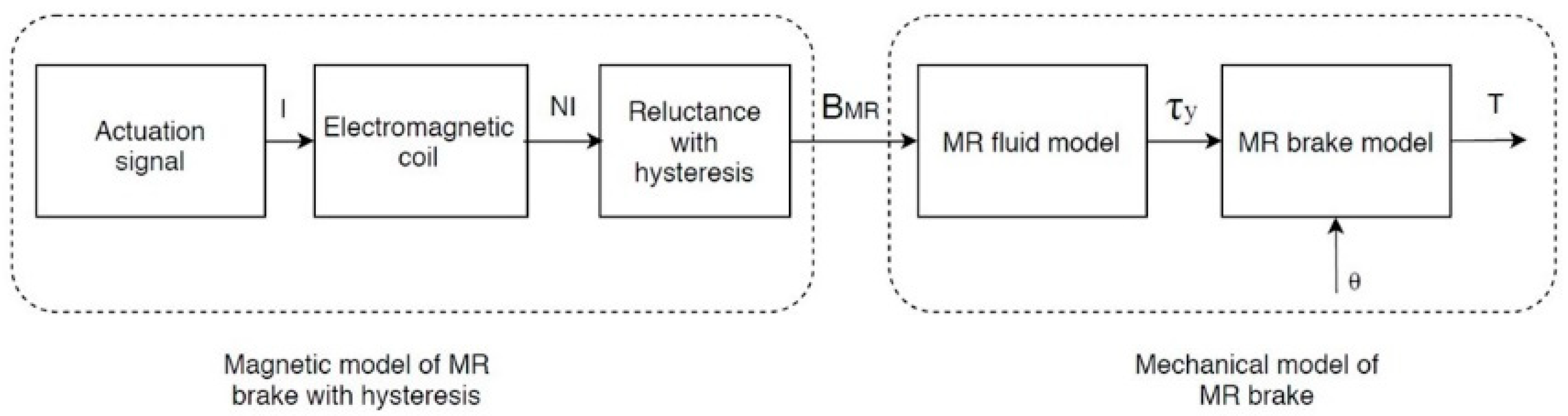
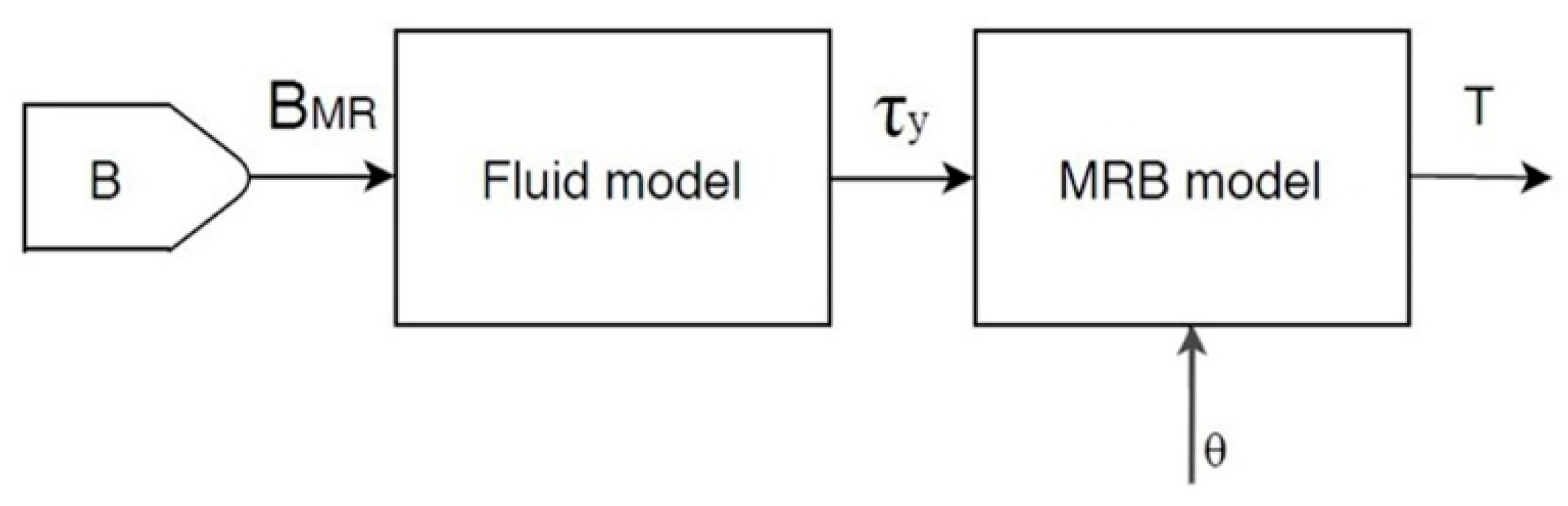
The coil inside an MR brake generates a magnetic field whenever current passes through it. This magnetic field is enhanced by the ferromagnetic core to which the coil is wounded. The increase of the magnetic flux depends on various parameters such as the number of coil turns, the current passing through the coil, core area, and core material, etc. For the factors affecting the flux of an MR brake, the current has a variable value, and the remaining parameters are constant. In the case of a PWM actuation signal, the current is variable. Therefore, the magnetic field (H) also varies to the input current. However, there is a nonlinearity between the applied magnetic field (H) and the magnetic flux density (B) in the material. Because the torque of an MR brake depends on magnetic flux density (B), there are nonlinear behavior shifts between output torque and input current. The paragraph below explains why and how the hysteresis arises in a material.
Although the current in the coil increases, the ferromagnetic core inside the MR brake is magnetized and reaches its saturation. In other words, the domains in the material are aligned in uni-direction. However, although the level current decreases and reaches zero, the material does not demagnetize itself in the initial path. It means that not all the domains in the material are dealigned. Only a few of them change their orientation back to their original state. This causes the material to retain some magnetic field and is called retentivity or magnetic remanence of the material. It leads to an increase in the off-state torque of the MR brake. To eliminate this effect in the system, an opposite current is usually applied until the magnetic remanence becomes zero. This is called the coercivity of the material. If the current is further increased in the opposite direction, the material reaches saturation in the opposite direction. In other words, the domains in the material are oriented in the opposite direction. Although the value of negative current decreases and reaches zero, the material still retains some magnetic field. To make it zero, a positive current must be applied. This forms a hysteresis loop. The area inside the loop is hysteresis loss. Soft magnetic materials have fewer hysteresis losses and hard magnetic materials have more hysteresis losses.
To use a PWM signal to eliminate nonlinearity in torque control, a hysteresis controller needs to be designed separately. This makes a system complex and expensive. The simulated model aims to operate the MR brake between the saturation and retentivity points of the hysteresis loop. The slope of the hysteresis loop in this region along with the self-inductance of the coil helps the torque of the MR brake not to collapse instantaneously to the input current. By considering this as an advantage the power to the coil can be turned off until the torque drops to an acceptable range. This can be achieved using a PWM actuation signal. At high frequencies, the torque drop is less. This makes to choose a high-frequency actuation signal to reduce the current drop (∆I) in the coil. The duty cycle of the PWM signal is varied for the required output torque. The conventional method uses a DC voltage control method in which current to the coil is supplied continuously to maintain the required torque. This way causes high power consumption. As mentioned above using the PWM actuation signal turns the hysteresis into an advantage and reduces the power consumption of the MR brake.

3. Simulation Model

It is a novel approach to simulate the hysteresis in MR brakes. Models of MR devices usually comprise electrical and mechanical systems as shown in Figure 1. This model aims to investigate the hysteresis effect on the torque performance of the MR brake and save the power consumption of the MR brake by turning the hysteresis into an advantage. A nonlinear reluctance with hysteresis block is used in the EM model to implement the relationship between magnetic flux density (B) and magnetic field strength (H). This block realizes the hysteresis effect inside the MR brake. DC and PWM actuation signals are given to the MR brake model in the simulation. The B-H relationship in the EM model varies with respect to the actuation signal, its frequency and duty cycle. This model studied the effects of hysteresis, frequency, and duty cycle on the torque performance of MR brake. The study revealed that the PWM actuation signal can be used to turn the hysteresis into an advantage. Analysis of the simulation results found the optimal frequency and duty cycle for the PWM signal to save power and achieve steady torque. The electromagnetic model of the MR brake is constructed using simscape modeling. The physical model of MR brake gives the flux density in the MR fluid which is used to calculate the yield stress of the fluid. The mechanical model is implemented by creating Matlab functions and incorporating the relations to obtain yield stress from the flux density and calculate the torque of MR brake.

3.1. Electromagnetic Model of MR Brake with Hysteresis

In this model DC, sine, and PWM actuation signals are used to simulate the torque performance of the MR brake. The electromagnetic model (as shown in Figure 2) is a physical model of electric and magnetic circuits inside the MR brake. The electrical circuit consists of an actuation signal source, driver, resistor, and coil. The resistor represents the equivalent resistance of the coil (Rc) which has the value of 2.5 Ω, and the number of turns (N) in the coil is 150. The PWM signal is given to the H-bridge which drives the coil at 5 V and a maximum current of 2 A.
The duty cycle of the PWM signal controls the current in the coil, and the frequency of the PWM signal affects the ripple in the current which in turn affects the magnetic field and the torque. The left portion of the above Figure 2 resembles the series RL circuit. One of the most important parameters of the RL circuit is the time constant (Tc). It is the time taken for the current in the coil to reach the steady state, and it also defines the response time of the MR brake. It is given by Equation (1).
T c = L c R c
where Lc is the inductance and Rc is the resistance of the coil. In MR brake’s the inductance of the coil is not constant. The coil inductance depends on the sum of all the reluctance in the magnetic circuit and is given by the ratio of the square of the number of turns to the reluctance in the magnetic circuit Equation (2).
L c = N 2 S Σ
Here N is the number of turns in the coil and SΣ is the sum of the reluctance in the magnetic circuit.
Various values of the duty cycle and frequency of the input PWM signal are simulated. From the simulation results, the optimal duty cycle and frequency are selected based on the obtained torque and the accepted ripple in the current. The electromagnet inside the MR brake generates magnetic flux when the current is passed through the coil. The flux requires a path to travel from the north to the south pole of the core. This path is provided by the components of MR brake such as core, rotating discs, and the MR fluid. The core and rotor discs are made of AISI 1010 and the MR fluid MRF-140CG is selected for the brake. The core and rotor discs act as reluctance (S) and exhibit much hysteresis than MR fluid. In a magnetic circuit, the opposition to the flux flow is caused by the reluctance of the circuit. It is calculated by Equation (3). It depends on physical geometry and the relative permeability of the material.
S = l µ r µ o A
where l is the length, A is the area of the cross-section, µr is the relative permeability of the material and µo is the permeability constant.
As we use variable PWM actuation signal the relative permeability of the material becomes the function of the applied field (H) and the magnetic flux density (B). The relationship between relative permeability, flux density, and applied field is given by Equation (4).
µ r = B µ o H
By substituting Equation (4) in (3) we obtain reluctance with the function of B & H in Equation (5).
S = lH BA
Hysteresis of the material affects the reluctance of the magnetic circuit. This effect is simulated in Matlab Simulink using a block nonlinear reluctance with hysteresis. It uses the equations proposed by Jiles and Atherton [5,6] to plot the hysteresis of the material. The block uses B-H data of the material to calculate the µr and S. The physical geometry and the B-H curve parameters of the core and MR fluid are incorporated in the block. The materials inside the MR brake which acts as reluctance are divided into segments with regular geometry. Each segment is represented with the block nonlinear reluctance with hysteresis and connected in series to provide a closed magnetic flux path. It estimates the drop in the flux density across the segments during OFF pulses of the PWM signal. A flux sensor is placed after the MR fluid reluctance to find the flux in the fluid. From Equation (3) the ratio of the flux flowing through the fluid to the area of the fluid gives the flux density (B). It is passed to the MR fluid model to calculate the yield stress of the MR fluid.

3.2. Mechanical Model of MR Brake

It consists of fluid model and the MRB model as shown in Figure 3. The main aspects of the mechanical model are the yield stress of the MR fluid and the torque of the MR brake. A polynomial equation is determined to implement B-H curve of MRF—140 CG in Matlab function. Applied magnetic field (H) is passed to this Matlab function, it gives the flux density in MR fluid (BMR).
Another aspect of the mechanical model is the MR brake model. The MR brake used in this research is a single-pole and multilayer magnetorheological brake. It has eight resistance layers in contact with the MR fluid. The applied magnetic field changes the viscosity of MR fluid and opposes the movement of these 8 resistance layers. The torque ( T M R ) depends on magnetic field strength and design constants. It is expressed by Equation (6).
T M R = A w 1 r τ d A w
where A ω is MR fluid contact area, r is the radius of the rotor, τ is the total shear stress of MR fluid.

3.2.1. MR Fluid Model

The behavior of MR fluid is represented by Bingham plastic model with a variable yield strength ( τ y ) based on magnetic field (H) as shown in Equation (7).
τ = τ y d + η ω r g
where τ y d is the yield shear stress due to magnetic field.

3.2.2. MR Brake Model

The design view of the single-pole multilayer MR brake is shown in Figure 4. The internal components of MR brake such as coil, MR fluid, multiple layers of the stator, and rotor discs can be seen in Figure 4a. After the assembly of the components isometric view of MR brake is shown in Figure 4b. The current passing through the coil generates a magnetic flux. It passes through the core and the MR fluid. The viscosity of the MR fluid changes and causes yield stress in the fluid between the multiple layers of the MR brake and resists the movement of the disc. The parameters that affect the torque of the MR brake are the viscosity (η), yield stress ( τ y ) and contact area of the MR fluid, the gap between the disc (g), outer radius (r2), and inner radius (r1) of the rotor disc, angular velocity (ω), and the amount of current passing through the coil (I). The number of layers increases the viscosity of the MR fluid. The net torque of a single-pole multilayer MR brake is calculated by Equation (11). ( T f r i c ) is the frictional torque of the MR brake.
The torque of the MR brake ( T M R ) is the sum of the yield stress torque ( T y d ) and the viscosity torque ( T v i s ) and is represented by the below Equation (8).
T M R = T y d + T v i s
The yield stress torque is given by the following Equation (9).
T y d = r 1 r 2 0 2 π r 2 τ y d d θ d r
The viscosity torque is given by the below Equation (10).
T v i s = η ω g r 1 r 2 0 2 π r 3 d θ d r
The total torque of the MR brake is calculated by Equation (11).
T = T M R + T f r i c = 8 [ 2 3 π τ y d ( r 2 3 r 1 3 ) + π η ω 2 g ( r 2 4 r 1 4 ) ] + T f r i c

3.3. MR Brake ANSYS Simulation

Initial validation of the Simulink model is accomplished by comparing its results with ANSYS simulation results with a DC actuation signal. MR brake is designed in ANSYS software with the same parameters as those in Simulink model. The B-H curve of MR fluid and material of the core are incorporated in ANSYS software during the design of MR brake. ANSYS uses finite element method to calculate flux density in MR fluid and across the MR brake components using this B-H curve. From Figure 5 it can be observed that flux density in MR fluid across the rotor disc is nearly 0.36 T. Technical data of MRF-140 CG provides yield stress of the MR fluid for a given magnetic field. It includes the friction of the MR fluid. This curve is incorporated in ANSYS simulation by the curve fitting equation to calculate the yield stress torque. Hence the yield stress torque obtained from ANSYS simulation also includes the friction. The torque equation of the MR brake is added to the ANSYS software. It computes the total torque from the yield stress torque and viscosity torque obtained from the brake model. The maximum torque obtained from this simulation is 13.08 (N-m). The comparison of results from ANSYS and EM model are discussed in Section 4.1. The flux density and the torque obtained from ANSYS closely matches with the EM model in Simulink.

4. Simulation and Experimental Results

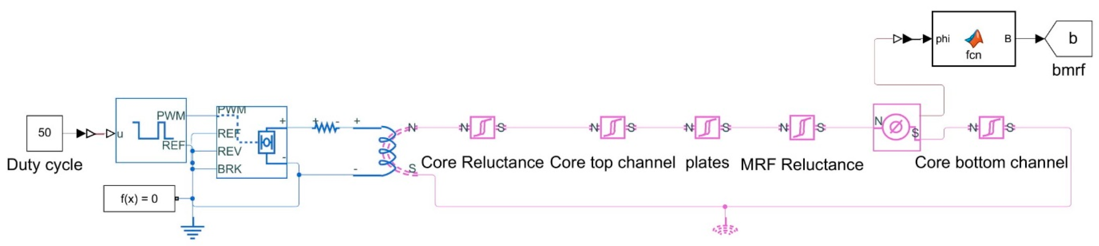
The torque of the MR brake is controlled by the input current to the coil. There are various actuation signals available to activate the electromagnet inside MR brake. Each signal has different effects on hysteresis, the inductance of the coil, and the torque of the MR brake. This paper aims to use the PWM actuation signal. It is interesting to investigate the effect of hysteresis on the torque performance of the MR brake for DC and PWM actuation signals. A physical model of the brake with electrical and magnetic circuits is constructed in Simulink. It helps to study the hysteresis effect on torque and power consumption of the MR brake with desired actuation signals.
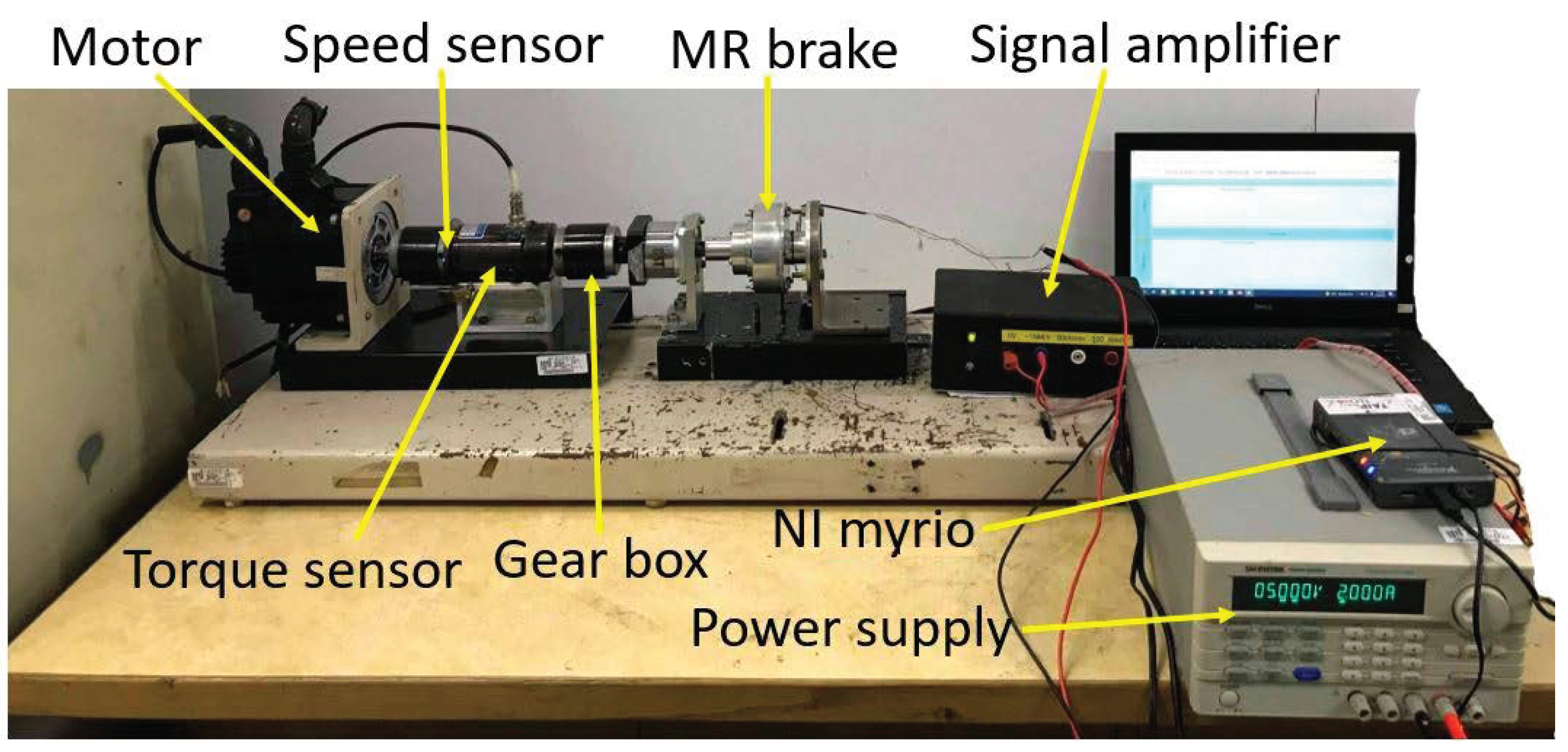
To understand the practical scenario a test bench for MR brake is constructed as shown in Figure 6. It consists of an MR brake, torque sensor, servo motor, gear box, signal amplifier, NI myrio, power supply and speed sensor. The shaft of the servo motor and the MR brake is coupled to the torque sensor. The servo motor is operated at 300 rpm. The power consumption and performance of the brake torque are tested with DC and PWM signals. The corresponding torque is obtained using NI myrio in labview software. The final validation of the simulated model is accomplished by comparing its results with experimental data.

4.1. DC Actuation Signal

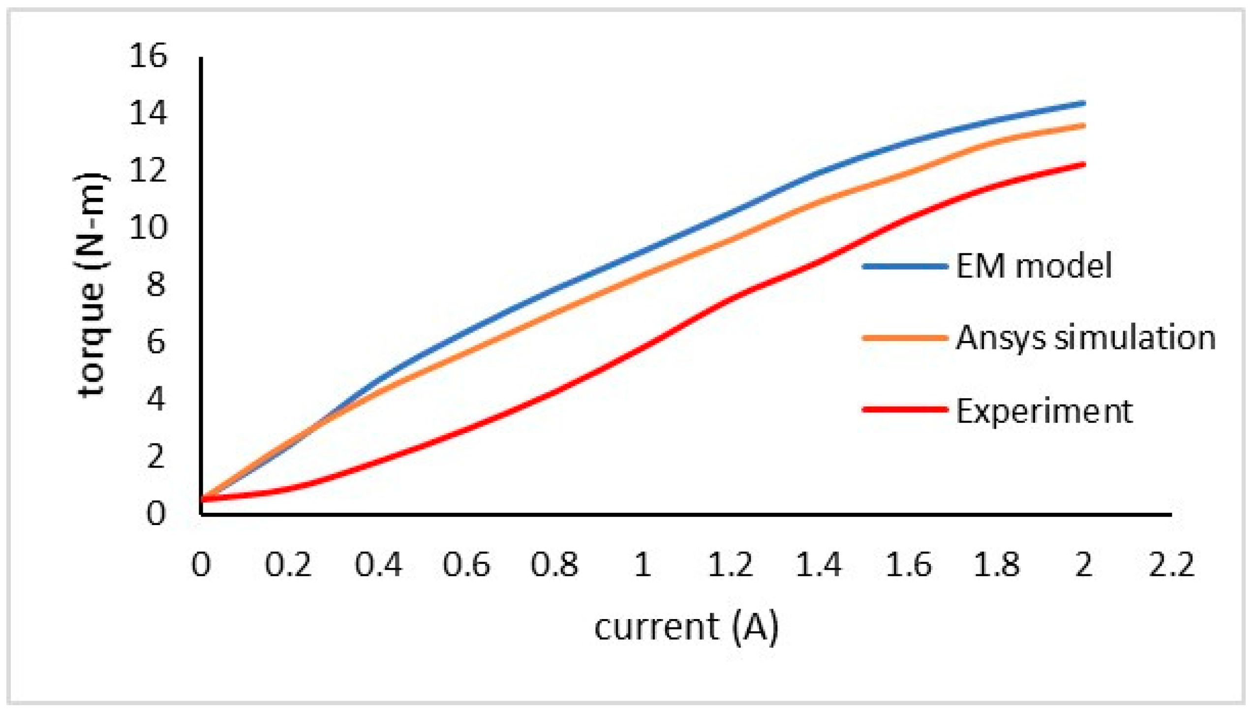
It activates MR brake with constant current and magnetic field. The current in the coil is controlled by the amplitude of DC signal. Simulation and experiment is run by incrementing the current value by 0.2 A and the corresponding torque value is noted. In the below 
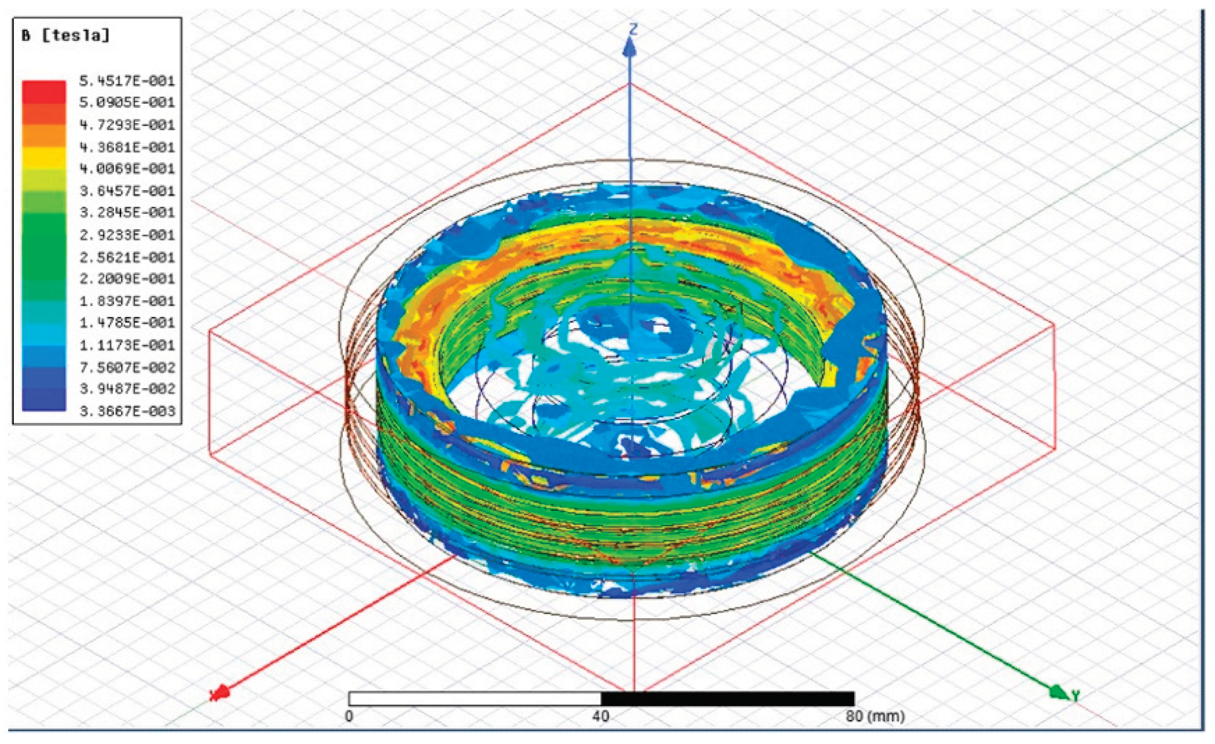
Table 1 we can see that B and T obtained from EM model and ANSYS simulation are nearly close. Simulation results are a little higher and there is a small torque difference of 2 (N-m) between the EM model and experimental results. The torque performance of EM model and ANSYS simulation is shown in Figure 7. It is observed that torque profile of MR brake obtained from EM model and experiment is similar. A uniform small error can be observed in the torque profile between the EM model and experimental results. The reason for the above differences is because, in the simulation model there is no air gap between the reluctances, coil and core. Therefore, electromagnet generates maximum flux which corresponds to maximum torque of the MR brake. This leads to the higher simulation torque. However, in the practical scenario a coil with the desired number of turns is placed inside the MR brake. Due to the manufacturing tolerances, there were small gaps during the assembly of the components, gap between core and coil, coil windings. These gaps contain air. Permeability of air is very low compared to the core and MR fluid. It reduces the amount of flux flow through the magnetic circuit. This reflects in the reduced torque in the experiment. Hence, our EM model is validated. The advantages of the DC actuating signal are current raises to the maximum and reached the steady state without any ripple. It provides a stable magnetic field and hence stable torque.

4.2. PWM Actuation Signal

It is an efficient method to control the MR brake with the PWM signal over the DC voltage control method. MR brake has a hysteresis effect on the torque performance. In this study, this effect is investigated to reduce the power consumption of the MR brake by turning the hysteresis into an advantage. MR brake with the hysteresis effect is simulated using the PWM actuation signal. PWM signal does not control current or voltage. It only switches the input power ON and OFF. The frequency of the PWM defines how fast it is switching and the duty cycle defines how long the power is ON for each cycle. The switching input creates a ripple in the coil current (∆I) which further creates a ripple in torque (∆T1) of the MR brake. The ripple in the current (∆I) must be minimized to obtain a stable magnetic field and torque. This is achieved in two steps. First, the frequency of the PWM signal is increased up to 5 kHz which reduced ∆I and ∆T1 to considerably low 3.3% and 0.2% respectively. Before we tune the second step, we need to know ∆T2 is the difference between torque obtained from the DC signal and PWM signal.
Figure 8 shows that ripple in current and torque is reducing with the increase in frequency. It is observed that ∆I and ∆T1 is high at low frequencies (1–100 Hz) and low at high frequencies (500 Hz–5 kHz). This phenomenon is because of the self-inductance and hysteresis effect in the MR brake. They oppose the rate of change in the current and magnetic field. At low frequencies, the current has enough time to rise to the maximum level and decay to the minimum level. This causes a high ripple in the current leading to the ripple in the magnetic field and the torque. In such cases, the back emf generated by the inductor is also high to oppose the change in the current. At high frequencies, the current does not have enough time to rise and decay to peak levels. Therefore, the rising and decaying levels of the current reduces which gives less ripple and low back emf. It leads to a stable magnetic field and torque.
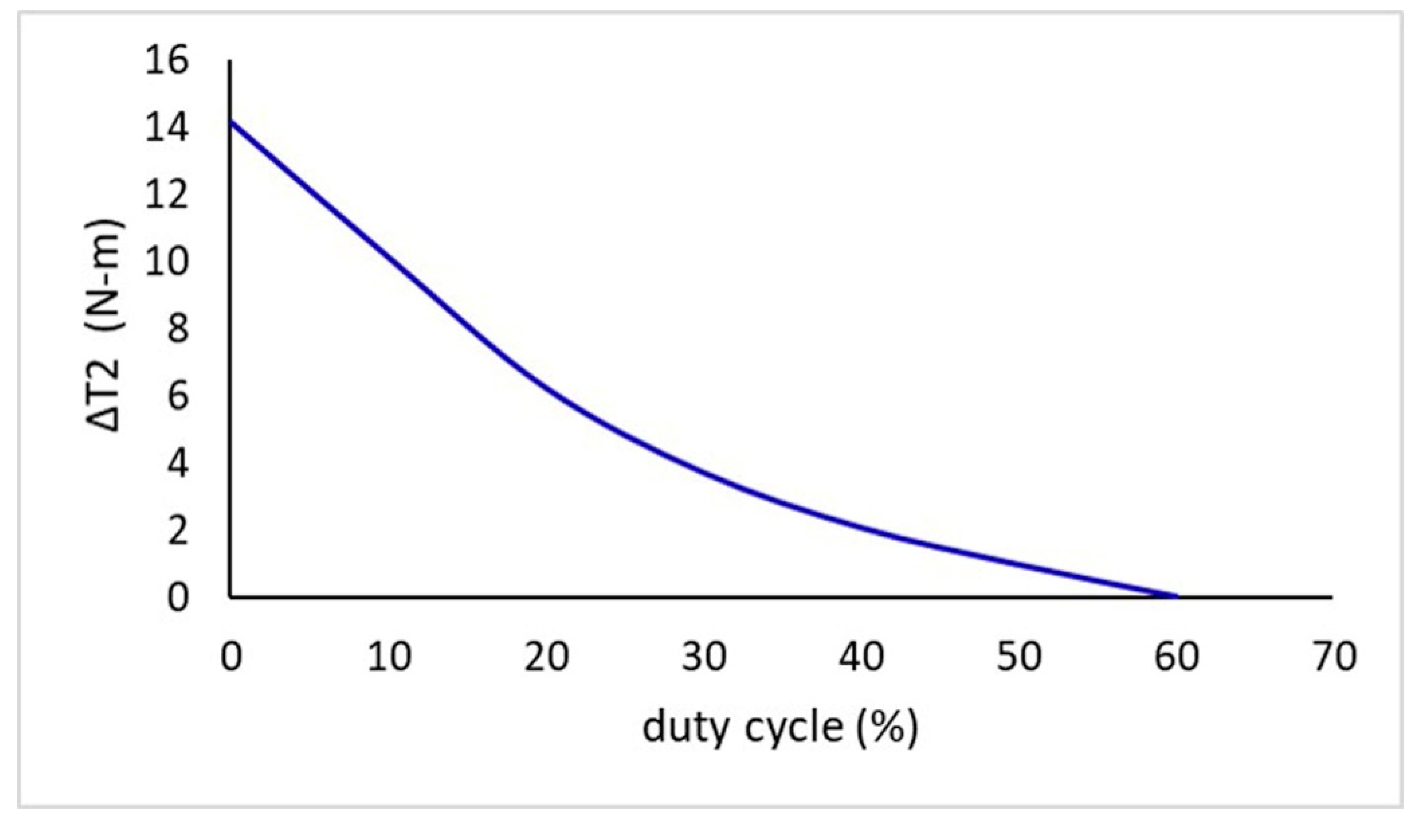
It is now interesting to investigate how ∆T2 varies with the duty cycle at optimal frequency. During pulse switching voltage rises and drops instantly but the current does not. This is because of back emf, the coil does not allow the current to change instantly. It instead takes one time constant to change the current through it. If the ON time is greater than the time constant of the circuit, current reaches the steady state maintains it until the OFF pulse. To save more power ON time is reduced to less than the time constant such that current immediately falls when it reaches steady state. Figure 9 shows that ∆T2 at 60% duty cycle is nearly zero. It means the PWM signal consumed only 60% of the input power to obtain the equivalent torque of DC signal with 0.2% ripple. Variable torque can be obtained by changing the duty cycle between 0–60%. It is clear from the simulation results that at 5 kHz frequency and 60% duty cycle are the optimal values for the selected MR brake with PWM actuation signal. At these optimal values, MR brake can obtain 99.8% steady torque by consuming 6 W of power. As explained earlier hysteresis in the core, the current and magnetic field in the coil does not collapse instantly. This maintains steady torque of the MR brake during the off pulse of the input signal due to the hysteresis effect which was explained previously. This effect is turned into an advantage by choosing PWM as an actuation signal which saves 40% power consumption of MR brake. Therefore, choosing a PWM signal is advantageous over a DC signal.
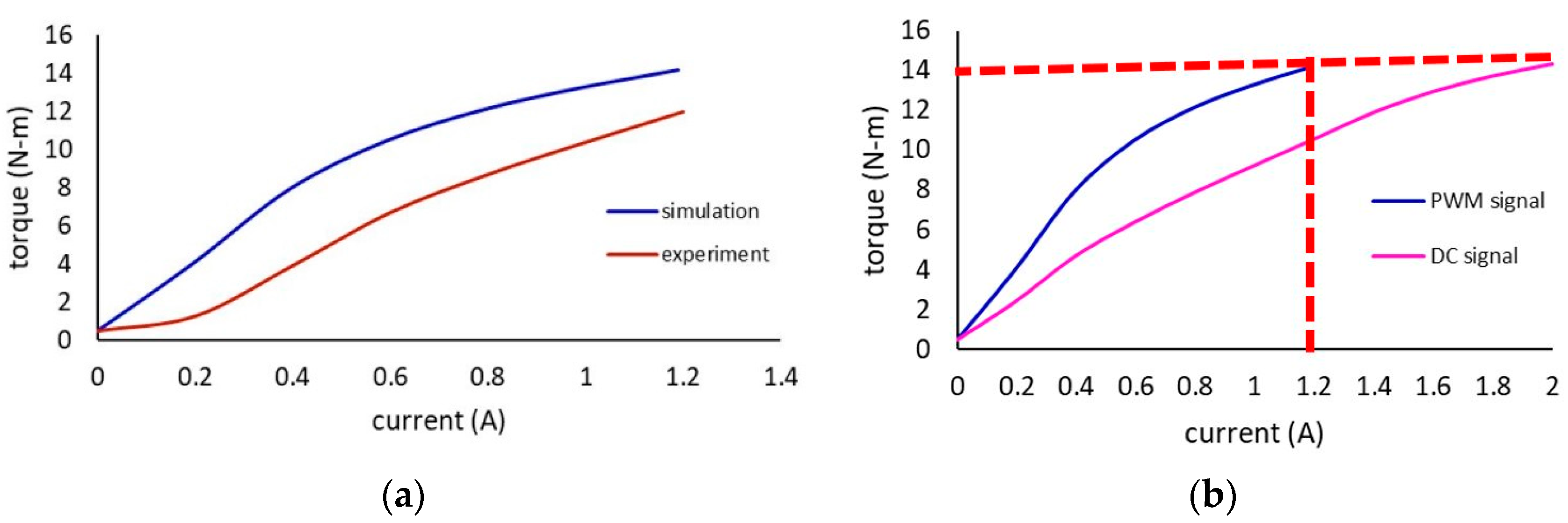
To understand the practical scenario and for the final validation of simulated model, MR brake is tested with PWM actuating signal at an optimal frequency and duty cycle. From the results, in Figure 10a it can be observed that torque profile of the simulation and experiment is similar. The reason for a uniform error between the simulation and experiment torque is discussed earlier in Section 4.1. MR brake produced required steady torque of 12 (N-m) by consuming 6 W power. Hence, it is proved that PWM signal provides a steady torque as a DC signal. It is observed from Figure 10b that there is not much difference in the torque profile of MR brake with the DC and PWM actuation signal. It is obvious that by choosing PWM as an actuation signal the torque performance of the MR brake is not affected. The red dashed line explains that the DC signal obtained 14 (N-m) torque at 2 A of current whereas PWM obtained the same torque level at 1.2 A. Table 2 shows that flux density and torque obtained by EM model across the rotor disc with PWM signal at 60% duty cycle is nearly same as the simulation torque with DC signal. It means flux density across the rotor disc is enough to maintain the required torque. In this way, the optimal frequency and duty cycle are chosen for the PWM signal. With the DC actuation signal power consumption of MRB is calculated as 10 W. the average power consumed by MRB with PWM actuation signal for 1 cycle at 5 kHz frequency and 60% duty cycle is 6 W. Therefore 40% power can be saved for 1 cycle using the PWM actuating signal compared to the DC signal.

5. Conclusions

In this study, a novel and simple method is proposed to investigate the hysteresis effect in the torque performance of MR brake. Initial validation of the Simulink model is done by comparing the Simulink results with ANSYS simulation results. An experimental test later validated the results of the simulated EM model. MRB torque performance is analyzed for DC and PWM signals by considering the hysteresis effect in core and MR fluid. From the simulation results, it is observed that MR brake consumed 10 W power and maintained steady torque with DC actuation signal. The hysteresis effect is studied using the new PWM actuation signal. The study revealed that the self-inductance and hysteresis effect in the core caused the current not to drop instantly. This effect is turned into an advantage using the PWM signal to save the power consumption of MRB. The optimal frequency of the PWM actuating signal is found to be 5 kHz and the optimal duty cycle was 60%. It consumed 6 W and saved 40% power consumption of MR brake compared to DC actuation signal.

Author Contributions

Idea, concept of saving power by turning hysteresis into advantage and critical revisions in the manuscript were contributed by Y.S. P.G. designed Electromagnetic and mechanical model of MR brake in Matlab Simulink, collected the data and wrote the manuscript. All authors have read and agreed to the published version of the manuscript.

Funding

This research was funded by Ministry of Science and Technology, Taiwan, grant number MOST 106-2221-E-027-065.

Institutional Review Board Statement

Not applicable.

Informed Consent Statement

Not applicable.

Data Availability Statement

The data presented in this study are available in [https://lordfulfillment.com/pdf/44/DS7012_MRF-140CGMRFluid.pdf].

Acknowledgments

I would like to thank Ministry of Science and Technology (MOST), Taiwan for funding this work. Project no: MOST 106-2221-E-027-065.

Conflicts of Interest

The authors declare no conflict of interest.

References

  1. Hsu, S.-H.; Changcheng, C.; Lee, H.-J.; Chen, C.-T. Design and Implementation of a Robotic Hip Exoskeleton for Gait Rehabilitation. Actuators 2021, 10, 212. [Google Scholar] [CrossRef]
  2. Goo, A.; Laubscher, C.A.; Farris, R.J.; Sawicki, J.T. Design and Evaluation of a Pediatric Lower-Limb Exoskeleton Joint Actuator. Actuators 2020, 9, 138. [Google Scholar] [CrossRef]
  3. Vidal, A.F.P.; Morales, J.Y.R.; Torres, G.O.; de Jesús Sorcia Vázquez, F.; Rojas, A.C.; Mendoza, J.A.B.; Cerda, J.C.R. Soft Exoskeletons: Development, Requirements, and Challenges of the Last Decade. Actuators 2021, 10, 166. [Google Scholar] [CrossRef]
  4. Ma, Z.; Zuo, S.; Chen, B.; Liu, J. Friction Prediction and Validation of a Variable Stiffness Lower Limb Exosuit Based on Finite Element Analysis. Actuators 2021, 10, 151. [Google Scholar] [CrossRef]
  5. Gait Identification by Inertial Sensors for Control of Adaptive Knee Orthosis Device. Sens. Mater. 2017, 29, 1657–1665. [CrossRef] [Green Version]
  6. Pamungkas, D.S.; Caesarendra, W.; Soebakti, H.; Analia, R.; Susanto, S. Overview: Types of Lower Limb Exoskeletons. Electronics 2019, 8, 1283. [Google Scholar] [CrossRef] [Green Version]
  7. Beyl, P.; Naudet, J.; Van Ham, R.; Lefeber, D. Mechanical Design of an Active Knee Orthosis for Gait Rehabilitation. In Proceedings of the 2007 IEEE 10th International Conference on Rehabilitation Robotics, Noordwijk, The Netherlands, 13–15 June 2007; pp. 100–105. [Google Scholar]
  8. Weinberg, B.; Nikitczuk, J.; Patel, S.; Patritti, B.; Mavroidis, C.; Bonato, P.; Canavan, P. Design, Control and Human Testing of an Active Knee Rehabilitation Orthotic Device. In Proceedings of the 2007 IEEE International Conference on Robotics and Automation, Rome, Italy, 10–14 April 2007; pp. 4126–4133. [Google Scholar]
  9. Shiao, Y.; Hoang, T.; Kantipudi, M.B.; Kao, N.-C.; Lai, C.-H. Development of a Multilayered Magnetorheological Brake for Knee Orthosis Applications. J. CSME 2021, 42, 81–91. [Google Scholar] [CrossRef]
  10. Abdelhameed, E.H.; Sato, N.; Morita, Y. Design of a Variable Resistance Training System Using Rotary Magneto-Rheological Brake. In Proceedings of the 2017 3rd International Conference on Control, Automation and Robotics (ICCAR), Nagoya, Japan, 24–26 April 2017; pp. 293–298. [Google Scholar]
  11. Rabinow, J. The Magnetic Fluid Clutch. Electr. Eng. 1948, 67, 1167. [Google Scholar] [CrossRef]
  12. Avraam, T.M. MR-Fluid Brake Design and Its Application to a Portable Muscular Rehabilitation Device. Ph.D. Thesis, Universite Libre de Bruxelles, Brussels, Belgium, 2009. [Google Scholar]
  13. Rossa, C.; Jaegy, A.; Lozada, J.; Micaelli, A. Design Considerations for Magnetorheological Brakes. IEEE/ASME Trans. Mechatron. 2013, 19, 1669–1680. [Google Scholar] [CrossRef]
  14. Attia, E.M.; Elsodany, N.M.; El-Gamal, H.A.; Elgohary, M.A. Theoretical and Experimental Study of Magneto-Rheological Fluid Disc Brake. Alex. Eng. J. 2017, 56, 189–200. [Google Scholar] [CrossRef]
  15. Wang, D.; Hou, Y. Design and Experimental Evaluation of a Multidisk Magnetorheological Fluid Actuator. J. Intell. Mater. Syst. Struct. 2013, 24, 640–650. [Google Scholar] [CrossRef]
  16. Shiao, Y.; Nguyen, Q.-A. Development of a Multi-Pole Magnetorheological Brake. Smart Mater. Struct. 2013, 22, 065008. [Google Scholar] [CrossRef]
  17. Jiles, D.C.; Atherton, D.L. Theory of Ferromagnetic Hysteresis. J. Magn. Magn. Mater. 1986, 61, 48–60. [Google Scholar] [CrossRef]
  18. Jiles, D.; Atherton, D. Ferromagnetic Hysteresis. IEEE Trans. Magn. 1983, 19, 2183–2185. [Google Scholar] [CrossRef]
  19. Li, Z.; Gong, Y. Research on Ferromagnetic Hysteresis of a Magnetorheological Fluid Damper. Front. Mater. 2019, 6, 111. [Google Scholar] [CrossRef]
  20. Erol, O.; Gonenc, B.; Senkal, D.; Alkan, S.; Gurocak, H. Magnetic Induction Control with Embedded Sensor for Elimination of Hysteresis in Magnetorheological Brakes. J. Intell. Mater. Syst. Struct. 2012, 23, 427–440. [Google Scholar] [CrossRef]
  21. An, J.; Kwon, D.-S. Modeling of a Magnetorheological Actuator Including Magnetic Hysteresis. J. Intell. Mater. Syst. Struct. 2003, 14, 541–550. [Google Scholar] [CrossRef]
  22. Gonenc, B.; Gurocak, H. Virtual Needle Insertion with Haptic Feedback Using a Hybrid Actuator with DC Servomotor and MR-Brake with Hall-Effect Sensor. Mechatronics 2012, 22, 1161–1176. [Google Scholar] [CrossRef]
  23. Kaya, M.; Sakthivel, U.; Khalil, I.S.M.; Misra, S. Development of a Coil Driver for Magnetic Manipulation Systems. IEEE Magn. Lett. 2019, 10, 1–5. [Google Scholar] [CrossRef]
  24. Yang, L.; Duan, F.; Eriksson, A. Analysis of the Optimal Design Strategy of a Magnetorheological Smart Structure. Smart Mater. Struct. 2008, 17, 015047. [Google Scholar] [CrossRef]
  25. Data, L.T. MRF-140CG Magneto-Rheological Fluid; LORD Corp.: Cary, NC, USA, 2008. [Google Scholar]
  26. Jolly, M.R.; Bender, J.W.; Carlson, J.D. Properties and Applications of Commercial Magnetorheological Fluids. J. Intell. Mater. Syst. Struct. 1999, 10, 5–13. [Google Scholar] [CrossRef]
  27. Shiao, Y.; Lai, C.-H.; Kao, N.-C. Design of an Adaptive Knee Orthosis with High Torque-Volume-Ratio Brake. In Proceedings of the Fifth International Multi-Conference on Engineering and Technology (IMETI 2016), EDP Sciences, Taichung, Taiwan, 28 November 2016; Volume 1, p. 559. [Google Scholar]
Figure 1. Block diagram of the simulated model.
Actuators 10 00271 g001
Figure 2. Electromagnetic model of MR brake with hysteresis.
Actuators 10 00271 g002
Figure 3. Mechanical model of MR brake.
Actuators 10 00271 g003
Figure 4. Single-pole multilayer MR brake (a) cross-sectional view (b) isometric view [27].
Actuators 10 00271 g004
Figure 5. Simulation of magnetic flux density in the MRB.
Actuators 10 00271 g005
Figure 6. Test bench of MR brake.
Actuators 10 00271 g006
Figure 7. Torque performance of MR brake with DC actuating signal.
Actuators 10 00271 g007
Figure 8. Ripple in the current ∆I and torque (∆T1).
Actuators 10 00271 g008
Figure 9. Drop in torque with duty cycle at 5 kHz frequency.
Actuators 10 00271 g009
Figure 10. Torque performance of MR brake (a) Simulation and Experimental torque of MRB with PWM signal at 60% duty cycle (b) torque comparison of MR brake with PWM and DC signal.
Actuators 10 00271 g010
Table 1. Results of DC actuation signal.
Verification TypeParametersActuation Signal
B (T)T (N-m)Imax (A)
EM model0.3814.22DC
ANSYS0.3613.08
ExperimentNot measured12.2
Table 2. Results of PWM actuation signal.
Verification TypeParametersActuation Signal
B (T)T (N-m)I (A)
EM model0.37141.2PWM
Experiment 12
Publisher’s Note: MDPI stays neutral with regard to jurisdictional claims in published maps and institutional affiliations.

