Abstract
The contact force between the polishing tool and the workpiece is crucial in determining the surface quality in robotic polishing. Different from rigid end-effectors, this paper presents a novel compliant end-effector (CEE) for robotic polishing using flexible beams. The flexibility of the CEE helps to suppress the excessive displacement caused by the inertia of the polishing robot and avoids damaging the polishing tool and workpiece surface. In addition, the contact force can also be precisely estimated via the measurement of the CEE’s displacement using a capacitive position sensor. The design, modeling and experimental validation of the CEE are presented. Firstly, the analytical model of the CEE is established using the stiffness matrix method. Subsequently, the analytical model is verified by finite element analysis. Further, a prototype is manufactured, and its characteristics and performance are experimentally tested. The equivalent stiffness is measured to be 0.335 N/μm, and the first natural frequency along its working direction is 42.1 Hz. Finally, the contact force measurement using the CEE is compared with a force sensor. Under open-loop condition, the resolution of the contact force measurement is found to be 0.025 N, which makes the fine tuning of the contact force possible in robotic polishing.
1. Introduction
Polishing is an extremely important processing technology in improving the surface quality of the workpiece [1]. The control of the contact force between the polishing tool and the workpiece is crucial in polishing. Currently, manual polishing is still very common, especially in the fine polishing of complex surfaces [2]. However, the quality of manual polishing is highly dependent on the skills and experience of the practitioner, resulting in low production efficiency and poor consistency [3]. On the contrary, in various precision industries, robots have been more and more frequently used for deburring and polishing the workpiece surface [4]. Compared with manual polishing, in robotic polishing, the contact force can be precisely regulated using force sensing techniques. Therefore, how to precisely sense and maintain the contact force has become an important issue in the robotic polishing process [5,6].
In order to realize contact force control, there are two kinds of control methods: passive compliance and active compliance. The most straightforward way to control the contact force between the polishing tool and the workpiece surface is to use a linear spring or a compliance mechanism [7], i.e., the passive compliance control. The active compliance control is to realize the closed-loop control of the contact force through the force sensor. In active compliance system, the most widely used drivers are pneumatic cylinder [8] and voice coil motor [9]. In order to avoid excessive contact between the polishing tool and the workpiece surface, the polishing end effector should exhibit certain compliance characteristics. Currently, the end-effectors can be briefly divided into mechanical [10], pneumatic [11], electrical [12] and electromagnetic [13]. With the force feedback, the active compliance control can obtain a nearly constant contact force via adjusting the displacement between the polishing tool and the workpiece surface [14,15].
Li et al. proposed a novel macro-mini robot with active force control for robotic polishing [9]. In this design, a macro robot provides the posture control during polishing operations, and a high-bandwidth end-effector, the mini robot, realizes constant contact force control. Tian et al. set up an active and passive compliance control polishing model by explicit force control based on position, using a tilting polishing tool with an elastic sponge disk to achieve a relatively constant force control effect [16]. Fan et al. presented a novel smart end-effector for active contact force control by using a gravity compensated force controller and two novel eddy current dampers for vibration suppression in the robotic polishing of thin-walled blisks [17].
Although the above researchers realized the constant force control in polishing, they did not consider the impact of the excessive displacement caused by the inertia of the robot on the workpiece and the polishing tool. Du et al. designed a compliant end-effector, where the deformation of the rubber support was used to improve the compliance of the polishing system. At the same time, an adaptive anti-saturation integral separated fuzzy proportional–integral (PI) controller was designed to control the contact force by using a force sensor [18]. Wu et al. proposed a novel force-controlled spherical polishing tool combined with self-rotation and co-rotation motion, providing compliance and polishing force in the polishing process [19]. Mohammad et al. presented a novel design of a force-controlled end-effector for automated polishing. In this design, the polishing tool can be extended and retracted by a linear hollow voice coil actuator to provide compliance [1].
The compliant mechanism has the advantage of no gap and friction, no lubrication and assembly, and integrated design and processing [20,21,22]. It has been utilized in a wide range of applications, such as micro-electromechanical systems, scanning probe microscopes, ultra-precision machining, and biological cell operations [23,24,25]. Wei et al. proposed a novel end-effector based on constant force mechanism (CFM), a specially designed compliant mechanism featuring almost zero stiffness within the effective range. This is the first time that CFM is used in robotic polishing. The constant-force motion range acts as a damper to counteract the excessive displacement caused by the inertia, and thus the end-effector regulates the contact force passively [26]. Ding et al. proposed a novel CFM based on the combination of positive and negative stiffness mechanism by using folding beam and bi-stable beam mechanisms. Without using any additional sensors and control algorithms, the proposed CFM can produce a travel range in constant force manner [27]. However, in the above CFMs, the value of the constant force is predefined cannot be adjusted. Therefore, when the contact force needs to be adjusted to another value, the current CFM has to be replaced to another CFM with a new set of dimensions.
In this paper, a flexible beam based compliant end-effector (CEE) for robotic polishing is proposed, which is beneficial to solve the problem that the polishing tool and workpiece surface are damaged due to excessive displacement caused by the inertia when the polishing robot approaches the workpiece surface quickly. When the polishing tool contacts the workpiece surface, the elastic deformation of the CEE can act as a damper. Further, the contact force can also be calculated from the displacement and the stiffness coefficient of the CEE without the use of the force sensor. As a capacitive position sensor is used to measure the displacement, the accuracy of the contact force sensing can be guaranteed, which is important to improve the force control accuracy of robotic polishing.
The rest of this paper is arranged as follows: Section 2 gives the mechanical structure design and analytical stiffness model of the CEE for robotic polishing. Section 3 and Section 4 give the finite element analysis (FEA) results and the experimental verification, respectively. Finally, the conclusion is provided in Section 5.
2. Design and Analysis of the Compliant End-Effector
2.1. Mechanical Design of the Compliant End-Effector
The schematic diagram of robotic polishing is illustrated in Figure 1, where a robot arm is used to hold and moves the polishing tool across the workpiece surface. A pneumatic cylinder is used to push the polishing tool against the workpiece with controllable contact force. Different from the conventional active compliance design, an additional CEE is inserted between the slider of the pneumatic cylinder and the polishing tool. During polishing, the pneumatic cylinder moves the polishing tool toward the workpiece. When the polishing tool touches the workpiece surface, the moving plate of the CEE can move back and forth, following the variation of the contact force, as shown in the inset of Figure 1. The elastic deformation of the CEE can act as a damper, which is beneficial to stabilize the contact force.
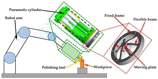
Figure 1.
Schematic diagram of the proposed CEE installed on an industrial robot arm.
Considering the possibility of the CEE’s failure and making it compatible for different robotic polishing tasks, a modular design is adopted herein such that the CEE can be easily replaced, as shown in Figure 1. In addition, due to the harsh polishing environment and the long working time, it is necessary to improve the adaptability of the CEE. Therefore, in the mechanical design of the CEE, very complex and tiny structures are not pursued. Considering the eccentric force generated by the rotation of the motor and the transverse force generated during polishing, six groups of flexible beams with completely symmetrical distribution are adopted in the design of the CEE, as shown in the inset of Figure 1. A flexible beam is adopted in construct the CEE because of its lower stress concentration and ease of manufacture when compared with the other types of flexure hinges. In order to further reduce the stress concentration, fillets are adopted at both ends of the flexible beams.
The proposed CEE also features precise contact force sensing capability. Within the elastic deformation range, the CEE can be treated as a linear spring with constant stiffness. In applications, the stiffness of the CEE can be calibrated in advance, and thus the contact force can be obtained via the displacement measurement of the CEE without the use of force sensor. In the prototype, high-precision capacitive displacement sensor is used as displacement feedback. Therefore, precise contact force sensing is also available.
The key design parameters of the CEE are the length l, the width b, the thickness t, and the rotating angle θ, as shown in Figure 2. As the designed CEE is used to obtain the contact force during robotic polishing, the design target value of the resolution of contact force is set to be below 0.1 N. Moreover, the deformation range should be as large as possible, because the CEE also acts as a damper when the polishing tool contacts the workpiece surface. In addition, the structure of this design is simple, and it does not need a complicated optimization program, so it is set manually herein. Finally, the main parameters of the flexible beam used are shown in Table 1.
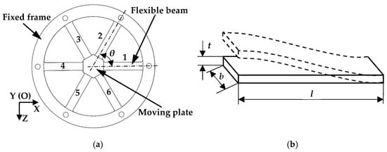
Figure 2.
Design parameters of the CEE: (a) overall structure; (b) the parameters of the flexible beam.

Table 1.
Key parameters of the flexible beam.
2.2. Analytical Modeling of the Compliant End-Effector
When the polishing tool touches the workpiece surface, the CEE can generate elastic deformations. The deformation of the CEE is dependent on its stiffness and the allowable stress. In order to obtain the displacement of the moving plate, a capacitive displacement sensor is placed behind the moving plate. The stiffness matrix method [28] shown below is used to obtain stiffness of the CEE.
where the mass matrix M = diag[mx my Jz] corresponds to the inertia mass and moment of inertia of the moving plate in its generalized coordinates q, mx and my represent the mass of the moving plate, and Jz indicates the moment of inertia of the moving plate on Z axis. The stiffness matrix K is
where is the stiffness matrix of a single flexible beam, and
As presented in Equation (3), [dxj 0 dzi]T represents the distance from O-XYZ to Oi-XiYiZi. θi is the rotating angle of Oi-XiYiZi with respect to O-XYZ, as displayed in Figure 3. The values of all the above parameters are shown in Table 2.
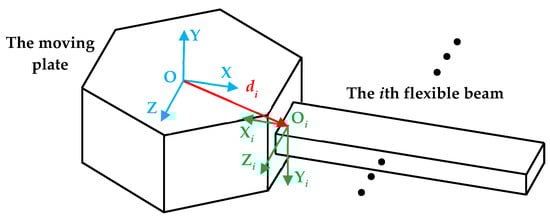
Figure 3.
The moving plate connected with the ith flexible beam.
Table 2.
Detailed parameters of matrix Ti.
The flexible beam used in this CEE is a straight beam, and its flexibility matrix expressed in its local coordinate is
where E and G are the elastic modulus and shear modulus of the material, respectively, and the stiffness matrix of the flexible beam is
The generalized force, F = diag[Fx Fy Mz], is applied on the moving plate. In terms of the static analysis, the relationship between the static force and displacement can be expressed as follows:
According to the vibration theory, the natural frequency f of the CEE can be obtained by solving the characteristic equation of |λI − M−1K| = 0,
When the contact force Fy is generated on the polishing tool, the output motion of the CEE can be calculated by Equation (6). Based on the above-mentioned method, the theoretical displacement u and stiffness k of the CEE along its working direction can be given by the following formulas:
3. Finite Element Analysis and Verification
In order to verify the static and dynamic performance of the CEE, the 3D model is constructed and imported into ANSYS Workbench for the FEA. The selected material is aluminum alloy 7075, and the elastic modulus E and Poisson’s ratio v are 70 GPa and 0.3, respectively.
3.1. Static Analysis Validation
The maximum force output of the pneumatic cylinder is 350 N. Therefore, in order to detect the maximum deformation of the proposed CEE, a force of 350 N is applied along its working direction. In this case, the deformation along the CEE working direction can reach 1.14 mm, as shown in Figure 4a. Through calculation, the stiffness k of the proposed CEE is 0.307 N/μm.
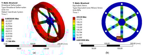
Figure 4.
FEA results of the CEE for robotic polishing: (a) deformation; (b) stress distribution.
Moreover, the static stress analysis is conducted to verify whether the safety factor is qualified, as shown in Figure 4b. The yield strength of Al 7075 is 503 MPa, and the maximum stress is 239.38 MPa. Hence, the safety factor is calculated as 2.10 (>1).
According to the different polishing requirements, the contact force generally varies within 10~40 N [1,16]. In this force range, the deformation and stress of the CEE are also obtained, which are 32.48~129.90 μm and 6.84~27.36 MPa, respectively, which are within the allowable elastic deformation range of the material.
3.2. Dynamic Analysis Validation
When the load of the CEE is 0 kg, the first natural frequency along its working direction is 501.93 Hz, as shown in Figure 5a. It is consistent with the analytic result (498.84 Hz). The second and third mode shapes are the rotations in the vertical direction and the horizontal direction, respectively, as shown in Figure 5b,c.
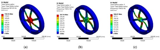
Figure 5.
The first three mode shapes of the CEE without load: (a) the first mode; (b) the second mode; and (c) the third mode.
In applications, the polishing tool and the connectors need to be installed on the moving plate of the CEE, i.e., the external loads to the CEE. In this case, the dynamic performance of the CEE will be influenced. Therefore, the corresponding theoretical calculation and FEA are also carried out to evaluate the influence of the external loads. For example, the load of the connecting flange installed on the CEE’s moving plate is 13.82 N, and the loads of the plastic and aluminum polishing tools (model: YQ060501, Shenzhen Han’s Robot Co., Ltd., Shenzhen, China) are 6.86 N and 9.02 N, respectively. When these loads are installed on CEE’s moving plate, the first natural frequency will be decreased. The variation of the first natural frequency against the external load is listed in Table 3.
Table 3.
Analytical model and FEA results of first natural frequency under different loads.
4. Prototype Fabrication and Experimental Test
4.1. Experimental Setup
In order to further verify the performance of the proposed CEE for robotic polishing, a prototype was fabricated using Al 7075 in a monolithic piece. In the fabricated prototype, the width b and the thickness t of the flexible beam slightly vary from the nominal values, and an increment of 0.1 mm is found. This magnitude of manufacturing error cannot be ignored. As a result, the measured dimensions of the CEE are adopted in the subsequent calculations. A force sensor (model: ZNLBS-V1-30 kg, Bengbu chino sensor Co., Ltd., Bengbu, China) is used to calibrate the contact force. A capacitive displacement sensor (model: NS-CDCS10L-400 with a resolution of 35 nm, Sanying Motion Control Instruments, Ltd., Tianjin, China) is used to measure the displacement. All force and displacement signals are acquired by a real-time target machine (model: Performance with a data acquisition card of IO133, Speedgoat). The overall experimental setup is shown in Figure 6.
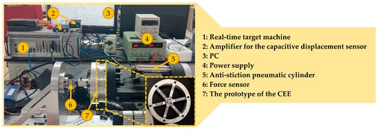
Figure 6.
Experimental setup of the proposed CEE for robotic polishing.
4.2. Test of Equivalent Stiffness
Firstly, the equivalent stiffness of the CEE is calibrated. A real-time control system is built on the real-time target machine. A stair signal with a step of 180 μm is set to the pneumatic cylinder under the open-loop condition. Under the excitation of this signal, the pneumatic cylinder pushes the CEE against the force sensor. The reaction force is measured by the force sensor, and the displacement of the moving plate of the CEE is measured by the capacitive displacement sensor. The measured force–displacement relationship is provided in Figure 7. Based on the measurements, the equivalent stiffness k of the CEE along its working direction can be calculated as follows:
where
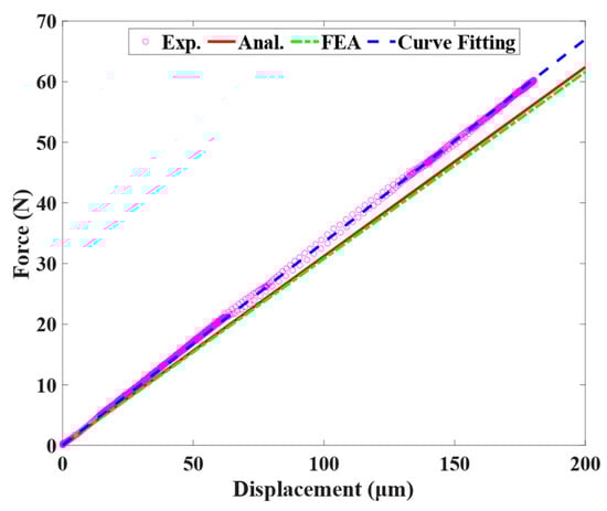
Figure 7.
Comparative analysis of the stiffness k of the CEE.
After the above treatment, the equivalent stiffness k of the CEE is calculated to be 0.335 N/μm. The equivalent stiffness k obtained from the analytical model and FEA results are 0.312 N/μm and 0.307 N/μm, respectively. The analytical and FEA results are also shown in Figure 7 as a comparison. Both the analytical model and FEA results slightly underestimate the equivalent stiffness, and the errors are calculated to be 6.87% and 8.36%, respectively.
4.3. Test of Contact Force Sensing
In order to verify the consistency between the contact force estimated by the CEE and that measured by the force sensor, a triangular wave is used to drive the cylinder to reciprocate and record the signal of force sensor and deformation displacement of the CEE in real time. The comparison results are shown in Figure 8a. It can be seen that the contact force estimated by the CEE is consistent with the force sensor. It further verifies that the contact force can also be calculated from the displacement and the stiffness coefficient of the CEE without the use of force sensor. Within the contact force range shown in Figure 8a, the maximum deformation and maximum stress of the CEE are 65.67 μm and 15.05 MPa, respectively, within the allowable elastic deformation range of the material.
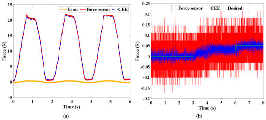
Figure 8.
Comparison of contact force obtained by force sensor and CEE: (a) consistency of measurement results; (b) resolution of contact force.
In the meantime, a stair signal with 0.025 N height is used to drive the cylinder for force resolution test. As shown in Figure 8b, it can be found that the noise level of the force sensor is in the magnitude of 0.2 N, whereas the noise level of the CEE measurement is in the magnitude of 0.04 N. The contact force resolution obtained by using CEE instead of force sensor is 0.025 N, which is important to improve the force control of the robotic polishing process. All the above experimental tests are carried out under the open-loop condition.
4.4. Test of Natural Frequency
In order to obtain the natural frequency of CEE for robotic polishing, a modal hammer is used to apply an impact load along its working direction to excite the CEE. At the same time, the capacitive displacement sensor is used to measure its displacement. The time domain signal is recorded and shown in Figure 9a. The natural frequency of the signal is 42.1 Hz after fast Fourier transform processing, as shown in Figure 9b. The measured first natural frequency is lower than the FEA results. This might result from the compliance of the pneumatic cylinder and the additional loads and accessories installed on the CEE during the test, such as the end cap.
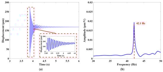
Figure 9.
Natural frequency test for the CEE: (a) time domain signal; (b) frequency domain signal.
5. Conclusions
This paper presents a novel design of the CEE for robot polishing using flexible beams. Compared with the conventional rigid end-effector, the elastic deformation of the CEE can act as a damper when the polishing robot installed polishing tool approaches the workpiece surface quickly. This design can help to solve the problem of excessive displacement caused by the inertia of the polishing robot and avoid damaging the polishing tool and workpiece surface during the polishing process. Further, the contact force can also be estimated from the displacement of the CEE without the use of a force sensor. Firstly, the equivalent stiffness and dynamic characteristics of the proposed CEE are carried out by means of analytical modeling and FEA. Then, a series of experimental tests are performed to verify its comprehensive performances. The experimental results demonstrate that the stiffness of this CEE is 0.335 N/μm. The resolution of the contact force measurement under open loop is found to be 0.025 N. Finally, the first natural frequency along its working direction is 42.1 Hz. All of the above work makes the fine tuning of the contact force possible in robotic polishing.
Author Contributions
Y.Q.: Conceptualization, methodology, resources, review and editing, supervision, project administration, funding acquisition; H.W.: conceptualization, methodology, validation, formal analysis, data curation, writing—original draft preparation; Z.L.: validation, formal analysis, data curation; N.S.: conceptualization, review and editing; L.S.: conceptualization, review and editing, resources, project administration, funding acquisition. All authors have read and agreed to the published version of the manuscript.
Funding
This work was supported in part by the National Natural Science Foundation of China under Grant 61873133, Grant 62173192, and Grant 52005270; and in part by the Natural Science Foundation of Tianjin under Grant 21JCZDJC00090.
Institutional Review Board Statement
Not applicable.
Informed Consent Statement
Not applicable.
Data Availability Statement
The data that support the findings of this study are available from the corresponding author upon reasonable request.
Conflicts of Interest
The authors declare no conflict of interest.
References
- Mohammad, A.E.K.; Hong, J.; Wang, D. Design of a force-controlled end-effector with low-inertia effect for robotic polishing using macro-mini robot approach. Robot. Comput.-Integr. Manuf. 2018, 49, 54–65. [Google Scholar] [CrossRef]
- Mohammad, A.E.K.; Wang, D. Electrochemical mechanical polishing technology: Recent developments and future research and industrial needs. Int. J. Adv. Manuf. Technol. 2016, 86, 1909–1924. [Google Scholar] [CrossRef]
- Tao, B.; Zhao, X.; Ding, H. Mobile-robotic machining for large complex components: A review study. Sci. China Technol. Sci. 2019, 62, 1388–1400. [Google Scholar] [CrossRef]
- Wan, S.; Zhang, X.; Wang, W.; Xu, M. Effect of pad wear on tool influence function in robotic polishing of large optics. Int. J. Adv. Manuf. Technol. 2019, 102, 2521–2530. [Google Scholar] [CrossRef]
- Tsai, M.J.; Huang, J.F.; Kao, W.L. Robotic polishing of precision molds with uniform material removal control. Int. J. Mach. Tools Manuf. 2009, 49, 885–895. [Google Scholar] [CrossRef]
- Liao, L.; Xi, F.; Liu, K. Modeling and control of automated polishing/deburring process using a dual-purpose compliant toolhead. Int. J. Mach. Tools Manuf. 2008, 48, 1454–1463. [Google Scholar] [CrossRef]
- Liu, C.; Chen, C.C.A.; Huang, J. The polishing of molds and dies using a compliance tool holder mechanism. J. Mater. Process. Technol. 2005, 166, 230–236. [Google Scholar] [CrossRef]
- Cheng, F.; Qi, Z.; Lei, Z.; Hong, Z. Development of the Polishing Tool System Based on the Pneumatic Force Servo. In Proceedings of the 2017 2nd International Conference on Advanced Robotics and Mechatronics (ICARM), Hefei and Tai’an, China, 27–31 August 2017; pp. 126–131. [Google Scholar]
- Li, J.; Guan, Y.; Chen, H.; Wang, B.; Zhang, T.; Liu, X.; Hong, J.; Wang, D.; Zhang, H. A High-Bandwidth End-Effector With Active Force Control for Robotic Polishing. IEEE Access 2020, 8, 169122–169135. [Google Scholar] [CrossRef]
- Tang, J.; Wang, T.; Yan, Z.Q.; Wang, L.W. Design and Analysis of the End-Effector of the Flexible Polishing Robot. Key Eng. Mater. 2016, 693, 58–63. [Google Scholar] [CrossRef]
- Tian-Soon, S.; Ang, M.H., Jr.; Kah-Bin, L. A compliant end-effector coupling for vertical assembly: Design and evaluation. Robot. Comput.-Integr. Manuf. 1997, 13, 21–27, 29–30. [Google Scholar] [CrossRef]
- Lopes, A.; Almeida, F. A force–impedance controlled industrial robot using an active robotic auxiliary device. Robot. Comput.-Integr. Manuf. 2008, 24, 299–309. [Google Scholar] [CrossRef]
- Kim, J.-D.; Noh, I.-H. Magnetic polishing of three dimensional die and mold surfaces. Int. J. Adv. Manuf. Technol. 2007, 33, 18–23. [Google Scholar] [CrossRef]
- Wahrburg, A.; Bos, J.; Listmann, K.D.; Dai, F.; Matthias, B.; Ding, H. Motor-Current-Based Estimation of Cartesian Contact Forces and Torques for Robotic Manipulators and Its Application to Force Control. IEEE Trans. Autom. Sci. Eng. 2018, 15, 879–886. [Google Scholar] [CrossRef]
- Ott, C.; Albu-Schaffer, A.; Kugi, A.; Hirzinger, G. On the Passivity-Based Impedance Control of Flexible Joint Robots. IEEE Trans. Robot. 2008, 24, 416–429. [Google Scholar] [CrossRef]
- Tian, F.; Lv, C.; Li, Z.; Liu, G. Modeling and control of robotic automatic polishing for curved surfaces. CIRP J. Manuf. Sci. Technol. 2016, 14, 55–64. [Google Scholar] [CrossRef]
- Chen, F.; Zhao, H.; Li, D.; Chen, L.; Tan, C.; Ding, H. Contact force control and vibration suppression in robotic polishing with a smart end effector. Robot. Comput.-Integr. Manuf. 2019, 57, 391–403. [Google Scholar] [CrossRef]
- Du, H.; Sun, Y.; Feng, D.; Xu, J. Automatic robotic polishing on titanium alloy parts with compliant force/position control. Proc. Inst. Mech. Eng. Part B J. Eng. Manuf. 2015, 229, 1180–1192. [Google Scholar] [CrossRef]
- Wu, X.; Huang, Z.; Wan, Y.; Liu, H.; Chen, X. A Novel Force-Controlled Spherical Polishing Tool Combined With Self-Rotation and Co-Rotation Motion. IEEE Access 2020, 8, 108191–108200. [Google Scholar] [CrossRef]
- Qin, Y.; Zhao, X.; Shirinzadeh, B.; Tian, Y.; Zhang, D. Closed-Form Modeling and Analysis of an XY Flexure-Based Nano-Manipulator. Chin. J. Mech. Eng. 2018, 31, 7. [Google Scholar] [CrossRef]
- He, S.; Tang, H.; Zhu, Z.; Zhang, P.; Xu, Y.; Chen, X. A Novel Flexure Piezomotor With Minimized Backward and Nonlinear Motion Effect. IEEE Trans. Ind. Electron. 2022, 69, 652–662. [Google Scholar] [CrossRef]
- Ma, X.; Liu, Y.; Deng, J.; Gao, X.; Cheng, J. A compact inchworm piezoelectric actuator with high speed: Design, modeling, and experimental evaluation. Mech. Syst. Signal Process. 2023, 184, 109704. [Google Scholar] [CrossRef]
- Wang, F.; Huo, Z.; Liang, C.; Shi, B.; Tian, Y.; Zhao, X.; Zhang, D. A Novel Actuator-Internal Micro/Nano Positioning Stage With an Arch-Shape Bridge-Type Amplifier. IEEE Trans. Ind. Electron. 2019, 66, 9161–9172. [Google Scholar] [CrossRef]
- Meng, Y.; Wang, X.; Huang, W.-W.; Li, L.; Hu, C.; Zhang, X.; Zhu, L. Intelligent Tracking Error Prediction and Feedforward Compensation for Nanopositioning Stages with High-bandwidth Control. IEEE Trans. Ind. Inform. 2022, 1–10. [Google Scholar] [CrossRef]
- Ding, B.; Li, X.; Li, Y. Configuration design and experimental verification of a variable constant-force compliant mechanism. Robotica 2022, 40, 3463–3475. [Google Scholar] [CrossRef]
- Wei, Y.; Xu, Q. Design of a new passive end-effector based on constant-force mechanism for robotic polishing. Robot. Comput. -Integr. Manuf. 2022, 74, 102278. [Google Scholar] [CrossRef]
- Ding, B.; Zhao, J.; Li, Y. Design of a spatial constant-force end-effector for polishing/deburring operations. Int. J. Adv. Manuf. Technol. 2021, 116, 3507–3515. [Google Scholar] [CrossRef]
- Lai, L.; Zhu, Z. Design, modeling and testing of a novel flexure-based displacement amplification mechanism. Sens. Actuators A Phys. 2017, 266, 122–129. [Google Scholar] [CrossRef]


Publisher’s Note: MDPI stays neutral with regard to jurisdictional claims in published maps and institutional affiliations. |
© 2022 by the authors. Licensee MDPI, Basel, Switzerland. This article is an open access article distributed under the terms and conditions of the Creative Commons Attribution (CC BY) license (https://creativecommons.org/licenses/by/4.0/).