Article

Topology Optimization of Shape Memory Alloy Actuators for Prescribed Two-Way Transforming Shapes

1
Laser Fusion Research Center, China Academy of Engineering Physics, Mianyang 621900, China
2
State IJR Center of Aerospace Design and Additive Manufacturing, School of Mechanical Engineering, Northwestern Polytechnical University, Xi’an 710072, China
3
Institute of Intelligence Material and Structure, Unmanned System Technologies, Northwestern Polytechnical University, Xi’an 710072, China
*
Author to whom correspondence should be addressed.
Actuators 2024, 13(2), 65; https://doi.org/10.3390/act13020065
Submission received: 10 January 2024 / Revised: 28 January 2024 / Accepted: 30 January 2024 / Published: 11 February 2024
(This article belongs to the Section Actuator Materials)

Abstract

:
This paper proposes a new topology optimization formulation for obtaining shape memory alloy actuators which are designed with prescribed two-way transforming shapes. The actuation behaviors of shape memory alloy structures are governed by austenite-martensite phase transformations effected by thermal-mechanical loading processes; therefore, to realize the precise geometric shape variations of shape memory alloy actuators, traditional methods involve iteration processes including heuristic structural design, numerical predictions and experimental validation. Although advanced structural optimization methods such as topology optimization have been used to design three-dimensional (3D) shape memory alloy actuators, the maximization/minimization of quantities such as structural compliance or inaccurate stroke distances has usually been selected as the optimization objective to obtain feasible solutions. To bridge the gap between precise shape-morphing requirements and efficient shape memory alloy actuator designs, this paper formulates optimization criteria with quantitatively desired geometric shapes, and investigates the automatic designs of two-way prescribed shape morphing shape memory alloy structures based on the proposed topology optimization method. The super element method and adjoint method are used to derive the analytical sensitivities of the objective functions with respect to the design variables. Numerical examples demonstrate that the proposed method can obtain 3D actuator designs that have the desired two-way transforming shapes.

1. Introduction

The phenomenon of shape memory materials to produce reversible shape transformations under cyclical temperature variation is called Two-Way Shape Memory Effect (TWSME). The transformation strain can produce larger structural deformations than thermal expansions. Therefore, actuators that exhibit the TWSME have great application potential in various fields, such as aeronautics [1,2], soft robotics [3], and medical instruments [4] (see Figure 1). Among all the shape memory materials, shape memory polymers [5,6] (SMPs) and shape memory alloys (SMAs) [7] are the most widely studied. To obtain two-way shape-morphing SMPs with desired geometric patterns, researchers have utilized various approaches [8], such as designing specific macro composite structures, adjusting the chemical composition of the transition material phase, or using 3D-printed micro structural arrangements. The TWSME from SMP is limited to low actuation forces due to its polymer nature. Shape memory alloys have high actuation forces, excellent superelastic, and shape memory performances, thus attract continuously growing attentions [9]. Due to inherent martensite-austenite phase transitions, the shape-morphing precision of shape memory effect is influenced by multiple factors like the SMA material composition, macro structural configuration, and thermal–mechanical loading process, which vary from material to material [10]. Therefore, the efficient development of SMA actuators with desired two-way shape morphing requires investigations from both experimental and numerical perspectives [11]. Material experiments have been conducted for desired morphing shapes, such as laser processing [12], heat treatments [13], and “pre-training” [14]. Innovative designs of active jet engine chevrons [11,15] and smart morphing wings [16,17,18] have also been proposed.
Previous studies were based on heuristic arrangements of regular-geometry SMA actuators and traditional elastic structures to obtain the required actuation deformation. Numerically, the macroscopic [19,20,21,22] and microscopic [23,24,25] models have been studied to theoretically predict the superelasticity, shape memory effects and “training” effects of SMA materials and structures. Conventional SMA actuator configurations (such as beams, springs, and strips) integrated with elastic structures have been optimized to achieve the target shapes [26,27,28], resulting in limited actuation modes for smart morphing structures. Nevertheless, topology optimization methods have been used to design shape memory structures for preferred motion patterns. Maximization/minimization of quantities such as structural compliance, energy dissipation or inaccurate stroke distances has usually been selected as the optimization objectives [10,29,30,31,32]. Realizing topologically innovative designs of 3D SMA devices for desired spatial actuation shapes is expected to broaden the structural morphing functionality and application potentials, as complex-geometry SMA actuators, like lattice structures, have been manufactured by 3D-printing technology [33].
This study investigated the topology optimization design of SMA actuators that exhibit a predefined TWSME under prescribed thermal–mechanical conditions. Inherently, actuation deformations are generated mainly due to the transformation strain of SMA materials between the austenite phase and the martensite phase. By manipulating the SMA material spatial distribution as well as the phase transformation region, desired actuation shapes can be expected for optimized blueprint designs. To reduce the massive computational efforts for solving structural optimization problems with large-scale integer variables, the modified Solid Isotropic Material with Penalty (SIMP) material interpolation scheme has been introduced in the original SMA material constitutive model. Furthermore, the Heaviside projection function and minimum length constraints were considered to guarantee the geometrical regulations of SMA device designs [34]. Numerical examples show that the proposed method could obtain the optimized SMA actuator designs with desired two-way actuation shapes.
Following Section 1, which introduced the state of the art of smart material and structures with TWSME, the rest of the paper is organized as follows. Section 2 explains the basic ideas of constructing a new topology-optimization formulation for prescribed two-way shape-morphing SMA actuator designs. The nonlinear finite element analysis processes and analytical sensitivity derivation of the optimization responses are described in Section 3. Numerical examples are presented in Section 4, and the conclusions are given in Section 5.

2. Topology Optimization Method for Two-Way Shape-Morphing SMA Actuators

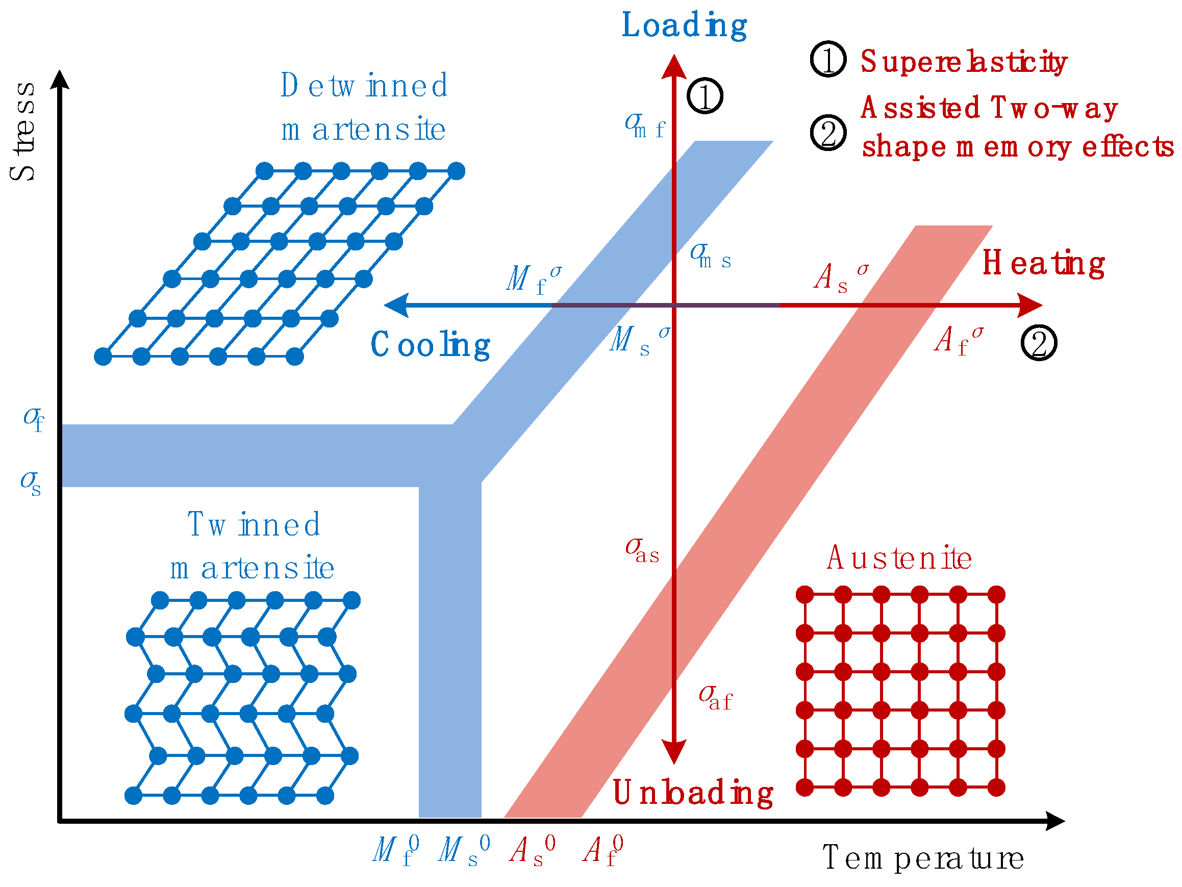
2.1. Material Constitutive Model for Shape Memory Alloys

The microscopic models [23,35], derived based on microscale theory, such as phase transition kinetics and crystal growth theory, are suitable for predicting the behaviors of SMA microstructures. The macroscopic models have few parameters and can represent the SMA continuum behaviors well with only a few experimental calibrations. Thus, they are computationally efficient for topology optimization of large-scale SMA actuators. In this work, the ZM material model [19] was used with sets of state variables to simulate the specific phenomena of SMA, including superelasticity, martensite orientation, and shape memory effects. The state variables are the macroscopic strain tensor ε, temperature T, local deformation strain tensors εA for austenite, local deformation strain tensors εM for martensite, martensite volume fraction z, and local martensitic reorientation strain εtr. Within the framework of generalized standards materials, the Helmholtz free-energy density of SMA materials is defined as:
W = W ( T , ε A , ε M , z , ε t r ) = ( 1 z ) ( 1 2 ε A : C A : ε A ) + z [ 1 2 ( ε M ε t r ) : C M : ( ε M ε t r ) + H ( T ) ] + G z 2 2 + z 2 [ α s z + β s ( 1 z ) ] ( 2 3 ε t r : ε t r )
where CA and CM are the austenite elastic modulus and martensite elastic modulus tensors, respectively. H(T) is heat density associated with the phase transformation and defined as H(T) = ξs(TAf0) + k. Af0 is the reverse phase transformation finish temperature; G, αs, βs, ξs, and k are parameters relevant to material properties. In the aforementioned formulation, (1−z)(1/2εA:CA:εA) is the free energy of austenite; z [1/2(εMεtr):CM: (εMεtr) + H(T)] is the free energy of martensite; Gz2/2 + z/2[αsz + βs(1−z)](2/3εtr:εtr) represents the interaction energy inside the SMA material. For the state variables ε, εA, εM, εtr, and z, the following physical constraints must be satisfied:
z 0   and   1 z 0  
( 1 z ) ε A + z ε M ε = 0  
ε 0 2 3 ε t r : ε t r 0
where ε0 denotes the maximum phase transformation strain. The Lagrange multipliers λ, μ, v1, and v2 are introduced to include the physical constraints into the total Helmholtz free energy L(W,Wcons):
L ( W , W c o n s ) = W + W c o n s = ( 1 z ) ( 1 2 ε A : C A : ε A ) + z [ 1 2 ( ε M ε t r ) : C M : ( ε M ε t r ) + H ( T ) ] + G z 2 2 + z 2 [ α s z + β s ( 1 z ) ] ( 2 3 ε t r : ε t r ) λ : [ ( 1 z ) ε A + z ε M ε ] μ ( ε 0 2 3 ε t r : ε t r ) v 1 z v 2 ( 1 z )
Thus, the stress–strain relation of SMA can be mathematically derived from Lagrange Equation (5):
σ = L ε = C e q : ( ε z ε t r )
where σ is the Cauchy stress tensor. A large deformation–small strain formulation is used to account for the evident shape morphing effects. Thermal strain is neglected here, considering its insignificant magnitude compared with that of the SMA phase transformation strain εtr.
The equivalent elastic modulus tensor Ceq is computed as SMA austenite–martensite mixture:
C eq = [ ( 1 z ) C A 1 + z C M 1 ] 1
Thermodynamic forces Az and Atr, which determine the evolution process of the martensite phase transformation and reorientation, can be derived from the Lagrangian L(W,Wcons):
A z = L z = 1 2 [ ε A : C A : ε A ( ε M ε t r ) : C M : ( ε M ε t r ) ] H ( T ) G z [ ( α s β s ) z + β s 2 ] ( 2 3 ε t r : ε t r ) λ : ( ε A ε M )
A t r = L ε t r = z { C M : ( ε M ε t r ) 2 3 [ α s z + β s ( 1 z ) ] ε t r } 2 μ 3 ε t r 2 / 3 ( ε t r : ε t r )
The pseudopotential D is defined as a function of the evolution ratio of martensite volume fraction z and martensite orientation strain εtr:
D = D ( z ˙ , ε ˙ t r ) = [ a ( 1 - z ) + b z ] | z ˙ | + z 2 Y 2 / 3 ( ε ˙ t r : ε ˙ t r )
where a, b, and Y are parameters relevant to the material properties. The thermodynamic forces Az and Atr are sub-gradients of the pseudopotential of dissipation D according to the theory of generalized standard materials. The yield functions associated with the forward phase transformation Fz1, reverse phase transformation Fz2, and martensite orientation Ftr can be defined as
F z 1 = A z a ( 1 z ) b z = { 1 3 E l MA σ VM 2 + 1 2 ( 1 3 E l MA + P MA ) ( t r σ ) 2 H ( T ) } + σ : ε t r ( G + b ) z a ( 1 z ) [ ( α s β s ) z + β s 2 ] ( 2 3 ε tr : ε tr ) 0
F z 2 = A z a ( 1 z ) b z = { 1 3 E l MA σ VM 2 + 1 2 ( 1 3 E l MA + P MA ) ( t r σ ) 2 H ( T ) } σ : ε tr + ( G b ) z a ( 1 z ) + [ ( α s β s ) z + β s 2 ] ( 2 3 ε tr : ε tr ) 0
F ori = F t r z = | A tr | VM z z Y = X VM z Y 0 with   X = σ 2 3 [ α s z + β s ( 1 z ) ] ε tr 2 μ ε tr 3 z 2 3 ε tr : ε tr
where Fz1 and Fz2 represent the forward transformation yield function (from austenite to martensite) and reverse transformation yield function (from martensite to austenite); Fori governs the detwinning process of twinned martensite, Y denotes the initiation yield stress of twinned martensite; ||X||VM is the von Mises equivalent of the thermodynamic force X; ElMA, PMA, αs, βs, a, b, and G are material parameters defining the superelastic hysteresis loops in the work of Zaki et al. [19]. The evolution laws of state variables z and εtr can be derived as
F Z 1 0 , z ˙ 0 , F Z 1 z ˙ = 0
F Z 2 0 , z ˙ 0 , F Z 2 z ˙ = 0
ε t r = 3 2 η X X V M = η N , F o r i 0 ,   η 0 ,   F t r η = 0
where η is a non-negative value related to the Kuhn–Tucker condition. N indicates the direction of the orientation strain rate in strain space. When simultaneously solving Equations (11)–(13) for predicting superelastic behaviors of SMAs, the coupling of multiple yield surfaces may lead to convergence difficulties and extensive computational efforts. To simplify numerical integration, martensite is assumed to be fully oriented by the applied stress as soon as the phase transformation from austenite to martensite takes place [36]. Therefore, the equivalent magnitude of the martensite transformation strain εtr is related to the martensite volume fraction z by the following equation:
ε tr = z ε 0 ; ε tr = 2 3 ( ε tr : ε tr )
The above material constitutive relations are solved using the classic plastic trial and correction method.
As shown in Figure 2, the Two-Way Shape Memory Effect (TWSME) can be found when SMA actuators go through temperature variations. When the SMA material temperature TL is higher than the austenite finish temperature Af0, the forward transformation and martensite orientation processes occur under external mechanical loading, resulting in a large transformation deformation along load path (1). If the external mechanical loading is kept constant and SMA device is heated uniformly to a higher material temperature TH, the large transformation deformation would vanish when detwinned martensite recovers to austenite phase via load path (2). Consequently, evident reversible structural shape transformations can be obtained via material temperature variations.
During the thermal-mechanical loading processes of TWSME, forward and martensite orientation transformations are associated with equations Fz1 = 0 and Fori = 0. Reverse transformation is associated with equation Fz2 = 0. The material constitutive relations are solved using the subroutine [19] at each numerical integration point of finite elements. Parameter values of SMA Material is provided in Table 1.
This study considers SMA material states related with following temperature conditions:
T = {TL, TH}
where temperatures TL and TH denote the low and high material temperatures, respectively. The temperature-sensitive superelastic behaviors of shape memory alloys are of great interest during applications.

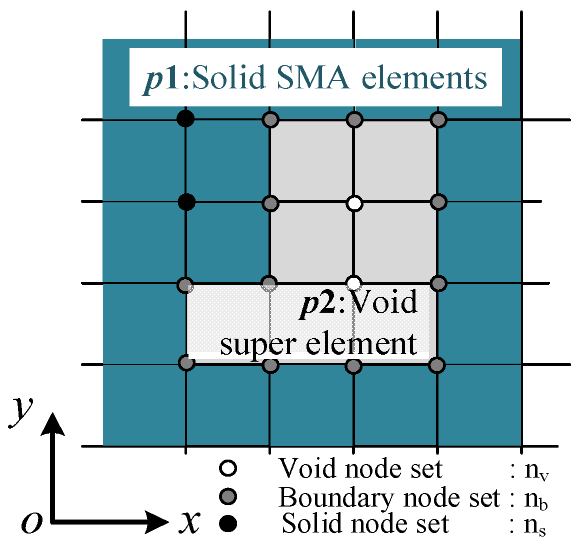
2.2. Material Interpolation Model for SMA

In the popular Solid Isotropic Material with Penalty (SIMP) topology optimization method, the pseudo-density variable ρ ¯ i = { 0 , 1 } determines the existence or absence of design material inside finite element i. When ρ ¯ i equals 1, the solid SMA material should be put inside finite element i. When ρ ¯ i equals 0, this means void material should be put inside finite element i. Normally, large-scale integer optimization problem requires enormous computational efforts to find a desired solution. For ease of the design problem, continuous pseudo-density variables were used here. In this work, the desired shape control was considered for the starting and ending temperature points. Only the Young’s moduli of austenite and martensite are interpolated with density variables. The influences of other parameters were proven to be negligible numerically, given that the optimization process sought to obtain “black and white” designs without intermediate density variables. Following the idea of Sigmund et al. [38,39], we interpolated the elastic moduli of austenite and martensite with the SMA material pseudo-density ρ ¯ i , as expressed in Equation (19).
C A ( ρ ¯ i ) = C A 0 P ( ρ ¯ i ) C M ( ρ ¯ i ) = C M 0 P ( ρ ¯ i ) P ( ρ ¯ i ) = C m i n + ρ ¯ p e ( C 0 C m i n )
Here, CA and CA0 denote the designed and solid Young’s moduli of the SMA austenite phase. CM and CM0 denote the designed and solid Young’s moduli of the SMA martensite phase. P(·) is the material interpolation function, with pe being the stiffness penalty factor. C0 and Cmin represent the unit value 1 and a small value greater than 0. It should be noted that intermediate density variables introduced artificial simulation responses to the analysis results (see Figure 3). Hence, the three-field scheme proposed by Wang et al. [40] was used in the following proposed topology optimization method. ρ ¯ i denotes the Heaviside filtered density, which was the physical density for the finite element analysis.
When the pseudo-density variable ρ ¯ i was close to zero, the constitutive curve became highly distorted, as shown in Figure 3. To accelerate the nonlinear analysis process, the constitutive material models for low density elements were simplified as linear elastic models. Meanwhile, the super-element technique [41] was adopted to alleviate the geometry distortions of low-density finite elements caused by large deformation.

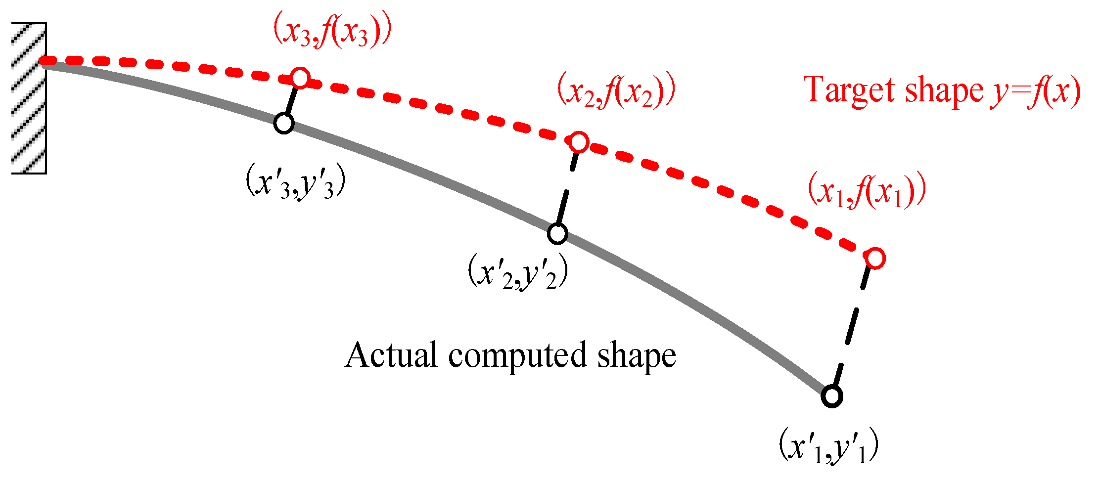
2.3. Definition of the Shape Error Function

As shown in Figure 4, the deviations between the actual computed shape and desired target shape can be defined as follows:
E r ( x , y ) = i = 1 m w 0 , i [ ( x i x i ) 2 + ( y i y i ) 2 ] = ( x x ) T W 0 ( x x ) + ( f ( x ) y ) T W 0 ( f ( x ) y )
where w0,i is the weighting factor of the ith observation point given by the designer. Er is the shape error function between target and actual shapes. W0 is the weight factor coefficient matrix. m is the total number of observation points. x and y are the coordinate vectors for target positions of the observation points. x′ and y′ represent the coordinate vectors for actual computed positions of the observation points. The shape error functions at different material temperatures {TL, TH} can be calculated as
E r L = ( x L x L ) T W 0 ( x L x L ) + ( f L ( x L ) y L ) T W 0 ( f L ( x L ) y L )
E r H = ( x H x H ) T W 0 ( x H x H ) + ( f H ( x H ) y H ) T W 0 ( f H ( x H ) y H )
where fL(·) denotes the mathematical function for desired structural target shape at the lower material temperature TL. fH(·) denotes the mathematical function for desired structural target shape at the higher material temperature TH. For the three-dimensional shape error calculation, Equations (20)–(22) can be easily extended with the third coordinate item.

2.4. Topology Optimization Model for Prescribed Two-Way Shape-Morphing SMA Actuators

The topology optimization model for the prescribed two-way shape-morphing SMA actuators is defined mathematically as follows:
Find : ρ i ,   i = 1 , 2 , , N ; Minimize   : E r L   Subject to : E r H   δ ; V f r a V 0 ;   g s δ s ;   g v δ v ; 0   ρ i   1   ;
Minimizing the shape error function ErL is chosen as the optimization objective. At the same time, the shape error function ErH is constrained below a small value δ. N denotes the total number of density design variables. The allowed material volume fraction Vfra of the design domain was set below V0. The geometric minimum length scale constraints gs and gv [34,42] for both the solid and void material were introduced into the topology optimization model to obtain “black and white” designs. δs and δv represent the upper-bound values. The globally convergent method of moving asymptotes (GCMMA) [43] is applied to solve the above optimization problem, which requires the derivative information of structural responses with respect to the design variables.

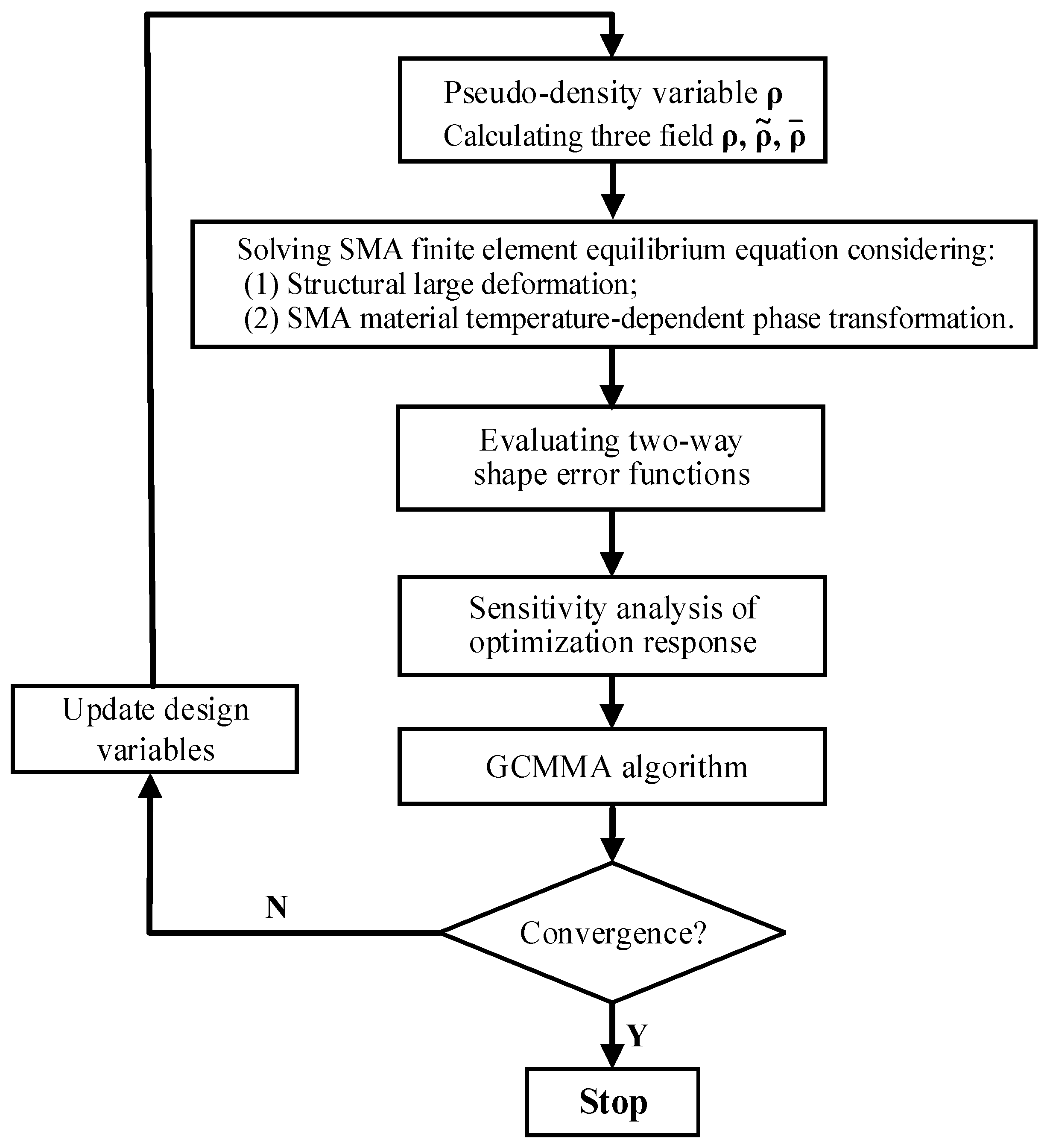
3. Nonlinear Finite Element Analysis and Optimization Response Sensitivity Analysis

3.1. Nonlinear Finite Element Analysis

In the SIMP topology optimization framework, fictitious regions [38], which are composed of finite elements with very low Young’s moduli, exist to imitate void regions. The fictitious regions enable different optimized topologies to be obtained using the fixed finite element mesh. When elements in low density areas have relatively large deformations, geometric distortions may occur and cause divergence of nonlinear analysis process. Various methods such as revising convergence criteria in the void regions [44], the additive hyperelasticity method [45], the energy interpolation method [46], and the super element method [41] have been proposed to alleviate the convergence difficulties. Here, the super element method was adopted to alleviate the numerical instabilities caused by weak elements of the topologically optimized SMA actuators.
A finite element equilibrium, accounting for the temperature-dependent superelastic behaviors of shape memory alloys, was found universally since we considered quasi-static deformations:
R 1 ( u ) = f e x t f int = 0
Equation (24) was solved using the Newton–Raphson method, expressed as follows:
{ u t + 1 = u t + Δ u t + 1 K T t Δ u t + 1 = Δ R 1 t
KT is the structural tangent stiffness matrix, which was computed by Equation (26).
K T = e = 1 N K T e ; K T e = Ω e B T C T B d v
K T e denotes the elemental tangent matrix of the eth element. B is the elemental geometric matrix.CT represents the consistent tangent moduli of the SMA material. KT is composed of several parts. As shown in Figure 5, the finite element model of the optimized SMA actuator can be divided into part p1 and part p2 by the pseudo-density threshold Dth. p1 is discretized with finite elements considering SMA material nonlinearity and geometric nonlinearity. p2 is modeled by linear elasticity material model and low-density elements, and their finite element degrees of freedom were suppressed in the total nonlinear iteration loop. Equation (25) can be further unfolded as follows:
[ K s s p 1 K s b p 1 K b s p 1 K b b p 1 + K ¯ ] [ Δ u s Δ u b ] = [ Δ R 1 , s Δ R 1 , b ]
According to the division of solid part p1 and void part p2, all nodes were divided into three groups (see Figure 5). Node type ns represented all the nodes surrounded by solid elements; node type nv represented all the nodes surrounded by void elements. Node type nb represented the nodes on the shared boundary of the solid elements and void elements. The block matrices Kss, Ksb, Kbb are stiffness matrices between nodes ns-ns, ns-nb, and nb-nb, respectively. denoted the additional stiffness brought to the boundary nodes nb by the void nodes nv in fictitious regions. It was calculated at the very beginning of nonlinear analysis on the undeformed configuration and remained unchanged during the iterations. The Newton–Raphson method in common finite element software is used to solve the material and geometrical nonlinear problem. Umat subroutine is programmed to capture the constitutive behaviors of SMA materials at each integration point of the finite element analysis.

3.2. Sensitivity Analysis of the Shape Error Optimization Response

The tangent stiffness matrix KT is also defined as
K T = R 1 t / u t
The detailed calculation procedure for nonlinear equilibrium can be found in the study of Zienkiewicz et al. [47] and is not stated here. By introducing the zero-valued item λ1TR1, the sensitivity of the shape error function with respect to projected density ρ ¯ i can be expressed as
( E r + λ 1 T R 1 ) ρ ¯ i = ( f ( x ) y ) T W 0 ( f ( x ) y ) ρ ¯ i + λ 1 T ( R 1 u u ρ ¯ i + R 1 ρ ¯ i ) = 2 ( f ( x ) y ) T W 0 ( f ( x ) y ) ρ ¯ i λ 1 T K T u ρ ¯ i + λ 1 T R 1 ρ ¯ i
The item ( f ( x ) y ) / ρ ¯ i can be further written as Equation (30).
( f ( x ) y ) / ρ ¯ i = f ( x ) / ρ ¯ i y / ρ ¯ i = f ( x ) x x ρ ¯ i y ρ ¯ i = ( f ( x ) x L x L y ) u ρ ¯ i
Lx and Lyare binary matrices to extract desired output displacement vectors from the global displacement vector u. Since λ is the Lagrange multiplier, which can take an arbitrary value, a particular value is selected according to Equation (31) so that the sensitivity of shape error function can be analytically computed:
2 ( f ( x ) y ) T W 0 f ( x ) x L x 2 ( f ( x ) y ) T W 0 L y = λ 1 T K T = F a d j T
By substituting Equations (30) and (31) into Equation (29), the analytical sensitivity information of shape error response with respect to density design variables is obtained:
E r ρ ¯ i = λ 1 T R 1 ρ ¯ i = λ 1 T ( f e x t f int ) ρ ¯ i = λ 1 T ( f e x t ρ ¯ i P ( ρ ¯ i ) ρ ¯ i f int P ( ρ ¯ i ) )

4. Numerical Examples

In this section, two kinds of SMA actuators are optimized with the proposed topology optimization method for desired two-way shape morphing. There are several aspects that need to be addressed:
(i) The desired target shapes should be compatible with the structural configurations and mechanical boundary conditions.
(ii) The relative deformations between two target shapes are in compliance with the magnitudes of transformation strain and structural dimensions.
(iii) The thermal–mechanical loading processes facilitated the forward and reverse transformations between martensite and austenite material phases of the SMA actuators.
The flowchart for the topology optimization of two-way shape-morphing SMA actuators is depicted in Figure 6. The convergence criterion for the topology optimization procedure is selected as: the maximum variation of the design variables between two adjacent iteration steps, which was less than 1 percent. The smoothed Heaviside projection factor β was increased gradually from 1 to 64 by a multiplying factor of 1.5 every 20 steps. The geometric minimum constraints are added to the optimization process when the discreteness of Heaviside filtered density ρ ¯ are below 10% [34]. The penalty factor pe was chosen as a constant value of 3. The pseudo-density threshold Dth was chosen as 0.1. Since the modified SIMP interpolation scheme was used, Cmin corresponding to void space was set one millionth of C0 = 1. To afford the computational effort, the reduced-integration 3D element is used. All numerical examples were run on a computer equipped with four-core CPU (clock speed 4.0 GHz) and 16 GB of RAM.

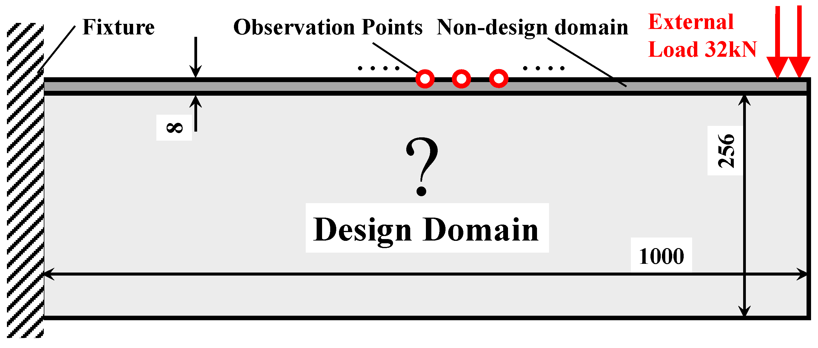
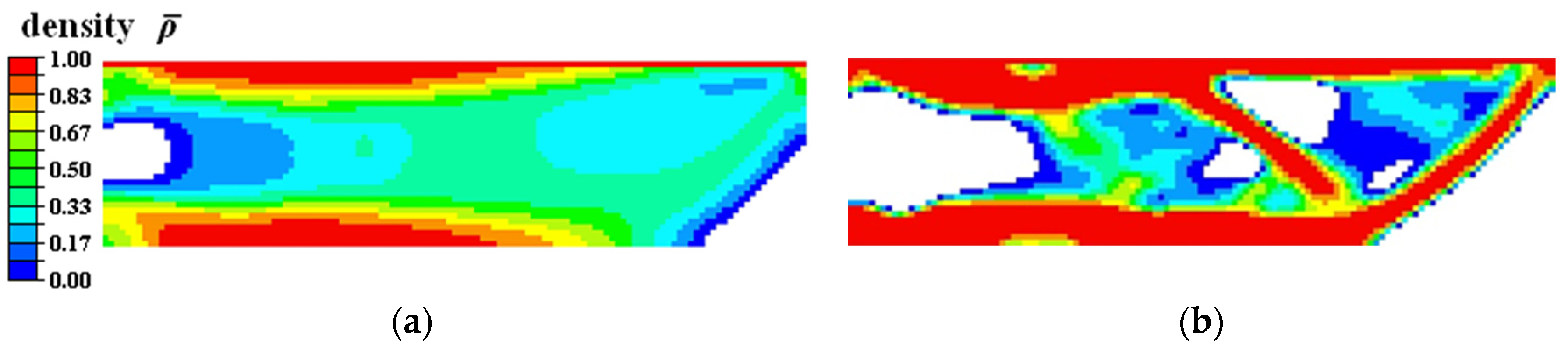
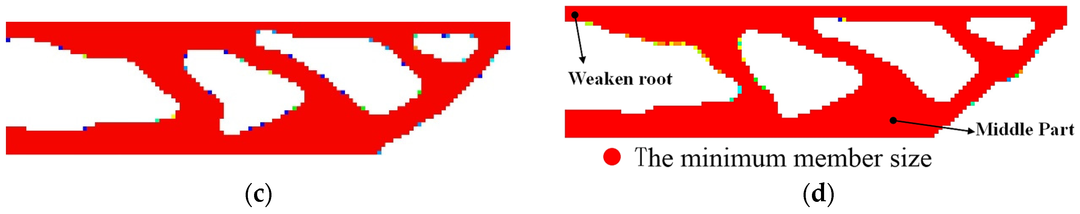
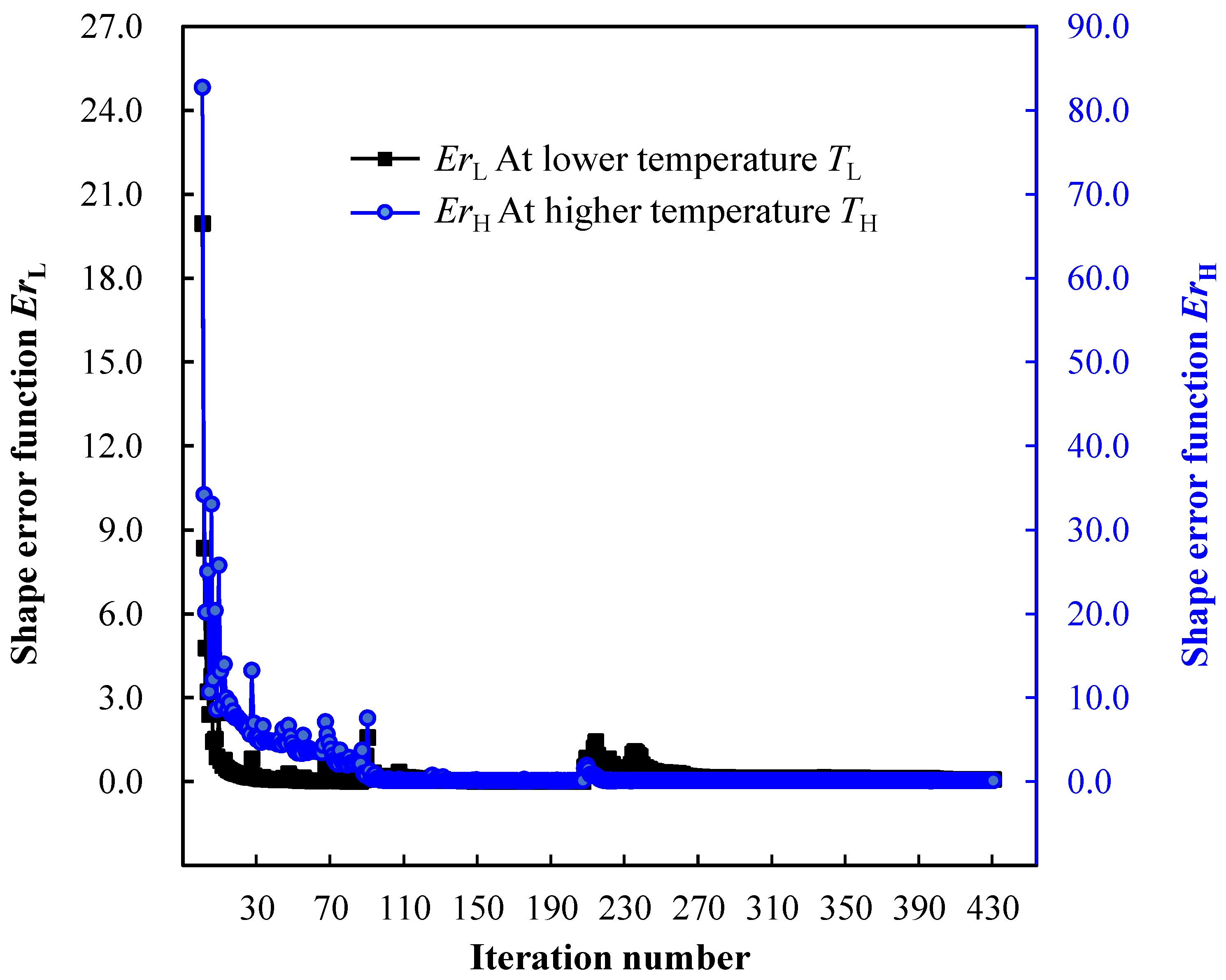
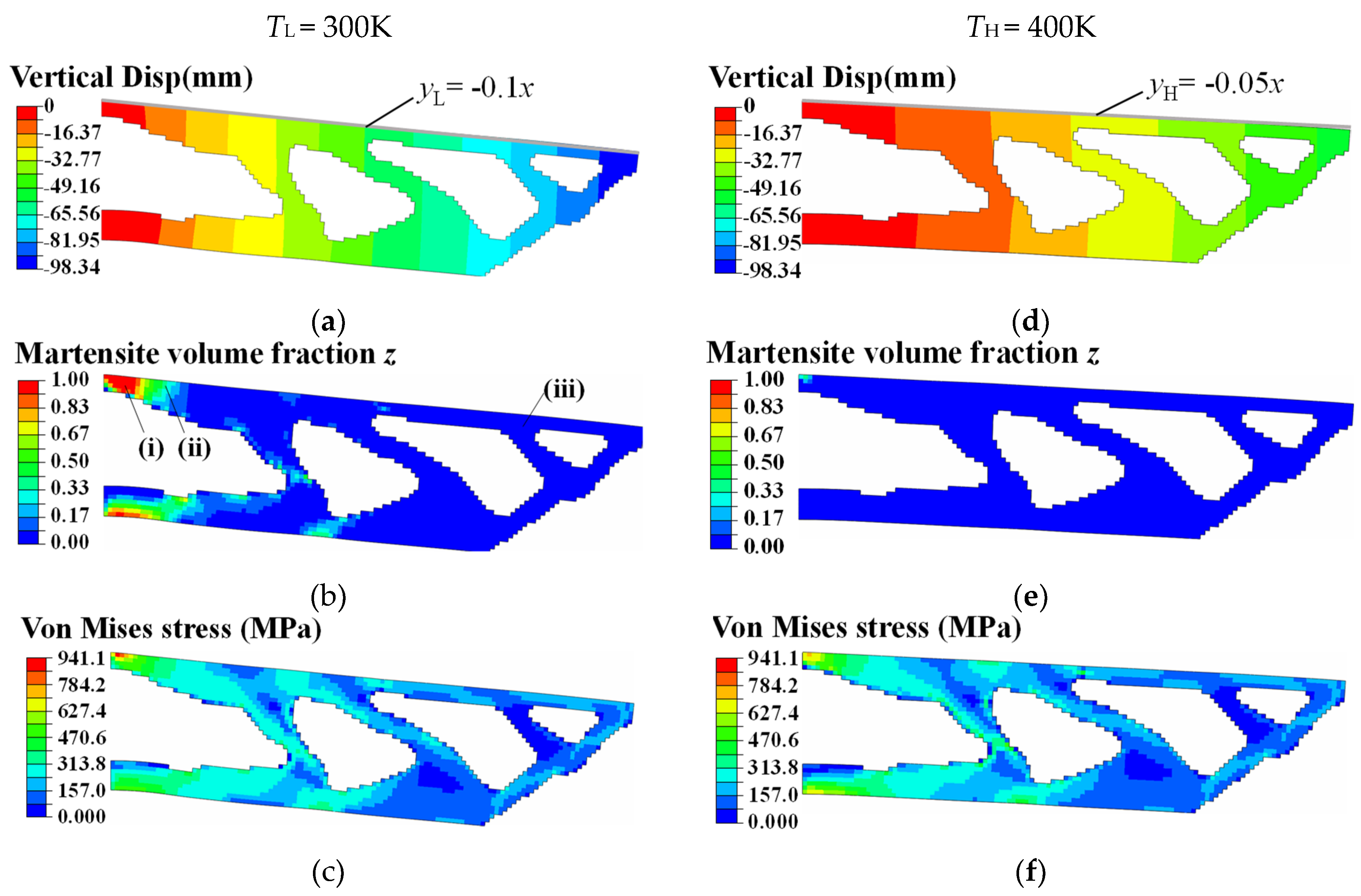
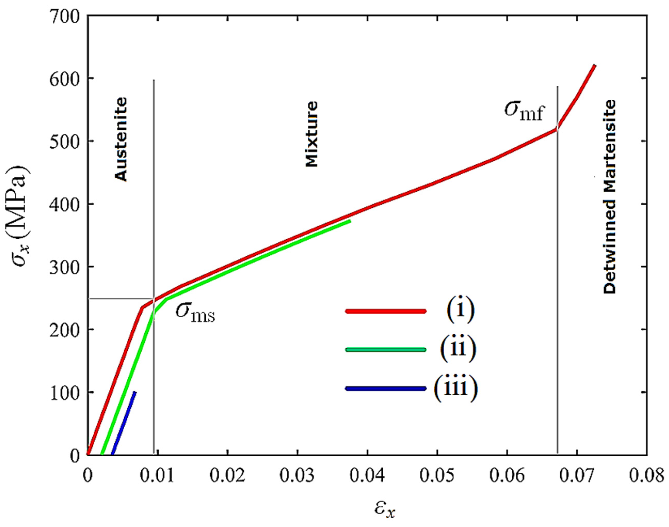
4.1. Topology Optimization of SMA Cantilever Beam for Prescribed Two-Way Shape Morphing

In this subsection, the topology optimization of an SMA cantilever beam is considered. Figure 7 shows the information of the detailed geometry and boundary condition. The SMA cantilever structure was discretized with finite elements with an average length scale of 8 mm. A total of 4215 3D solid finite elements with 8568 nodes were generated and arranged in one single plane. The upper-bound values δs and δv of geometric minimum length constraints were 1.0 × 10⁻⁵. The basic morphing shapes were defined as straight lines with different slopes. Their target shapes at two material temperatures {TL, TH} are given as follows:
y L = 0 . 1 x ; T L = 300 K
y H = 0 . 05 x ; T H = 400 K
The material parameters are listed in Table 2. The external mechanical load has a magnitude of 32 kN and is distributed uniformly in an area of 24 mm × 8 mm. Material volume fraction upper bound V0 was set as 50%; the density filter radius Rfilter was chosen as four times the average size of the finite elements. In total, 25 × 2 observation points were located equidistantly on the upper surface. To normalize the values of shape error functions, the weighting factor w0,i was chosen as the reciprocal of the desired displacement magnitude at the ith observation point. The shape error function ErH at the material temperature TH was constrained below δ = 0.1.
Figure 8 illustrates the topology evolution history of the SMA cantilever beam as the proposed optimization algorithm proceeded. The whole topology-optimization process for SMA cantilever beam took approximately 40 h. After 430 iterations, the topology optimization algorithm found a reasonable local optimum. The iteration history is plotted in Figure 9. The optimized SMA cantilever had a well-defined topological configuration and distinct material boundary, and satisfied the imposed minimum length and scale geometric constraints. The upper part of the fixed root was designed to be weak, and a massive amount of material was gathered in the middle part. This design scheme facilitated the desired slope deformation under the mechanical load.
As shown in Figure 9, the value of objective function ErL decreased from 19.950 to 0.079, while the value of the shape error constraint ErH evolved from 82.730 to 0.100, satisfying the prescribed upper-bound value δ. The final values of the shape error functions ErL and ErH were only 0.4% and 0.1% of the initial values, respectively. The optimization process only oscillated for a few iteration steps when the geometric minimum length constraints were strengthened.
The two-way shape-morphing patterns, martensite phase transformation regions, and structural stress distributions are depicted in Figure 10. As shown in Figure 10a,d, the upper surface of the topology-optimized SMA cantilever beam transformed precisely into the preferred slope configurations at material temperatures TL and TH, thus fulfilling the desired two-way shape morphing effect.
The internal mechanical principles are explained in the following. Under the conditions of the lower material temperature TL and the external mechanical load, the SMA material at the root of the cantilever beam detwinned from austenite to martensite (see Figure 10b,e), resulting in a reversible martensite transformation strain εtr. Meanwhile, the loaded upper surface approached the slope shape defined in Equation (33). According to Equation (17), there was a positive correlation between the transformation strain εtr and martensitic material volume fraction. As shown in Figure 10b and Figure 11(i), the complete martensite detwinning process occurred in the locations where the martensite volume fraction z equaled 1. Therein, the magnitude of the martensite transformation strain ||εtr|| reached ε0. The total mechanical strain ε comprised austenite elastic strain εA, martensite transformation strain εtr, and detwinned martensite elastic strain εM. As shown in zone (ii) of Figure 10b, a partial martensite detwinning process occurred in the locations where the martensite volume fraction z was in the internal of (0,1). Here, the magnitude of martensite transformation strain ||εtr|| was less than ε0, and the total mechanical strain ε comprised the austenite elastic strain εA and the partial martensite transformation strain εtr. As shown in zone (iii) of Figure 10b, the SMA material remained austenite in the locations where martensite volume fraction z equaled 0. Therein, the total mechanical strain ε only represented the austenite elastic strain εA.
Under the constant external load, when the SMA material was heated to a higher temperature TH, detwinned martensite in zones (i) and (ii) transformed reversely to the austenite phase (see Figure 2 and Figure 10e). The transformation strain εtr, which was proportional to the martensite volume fraction z, vanished. From a macroscopic point of view, the optimized SMA cantilever overcame the external load and produced actuation deformation, reaching the slope shape defined in Equation (34).
Figure 12 shows the topology-optimized results when we set minimizing compliance as the optimization objective. After 247 iterations, the algorithm evolved to a local optimum. In contrast to the cantilever design in Figure 8d, the SMA cantilever design in Figure 12a had a robust root near the fixture. The loaded upper surface deformed into an arbitrary curve shape, distorting the original geometric shape. A few areas of the SMA material detwinned into the martensite material phase. The maximizing stiffness optimization method was more likely to obtain SMA actuator designs that suppressed the forward transformation from austenite to martensite. The topology-optimization process converged stably, and the compliance iteration history of the optimized SMA cantilever is plotted in Figure 13.
The choice of the upper-bound value δ of ErH affected the topology optimization results, showing the necessity of considering shape error constraints in the prescribed material temperature TH. Figure 14 depicts a set of topology-optimized configurations when we selected different upper-bound values δ of ErH as the optimization criterion. When δ of ErH was set as a relatively large value of 1, the SMA cantilever design with the minimal value of shape error function ErL (about 0.0033) was obtained, as shown in Figure 14, design scheme I. This shows that the upper surface of the SMA cantilever design I approached the expected slope shape yL precisely, while it diverged from the slope shape yH with ErH of 0.7260. As the upper bound δ of ErH decreased from 1 to 0.01 (see designs II, III, IV and V), the SMA material redistributed from the left-side fixture region to the right-side loading region, to satisfy the strict shape error constraint ErH. As a consequence, the shape error function ErL at the material temperature TL increased from 0.0033 to 0.1330. The above results showed that minimizing the values of both shape error functions ErH and ErL was contradictory. Hence, a precision compromise is necessary for two-way shape-morphing designs when the uniform heating/cooling control strategy is adopted.

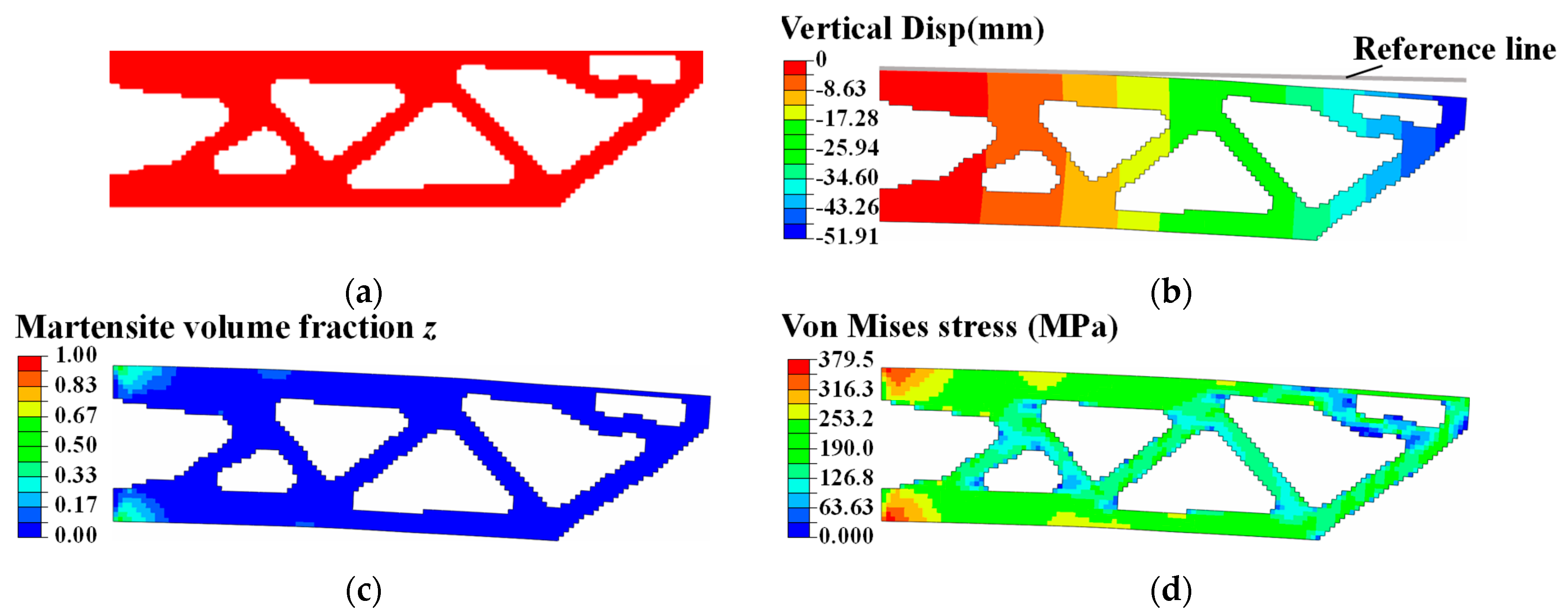
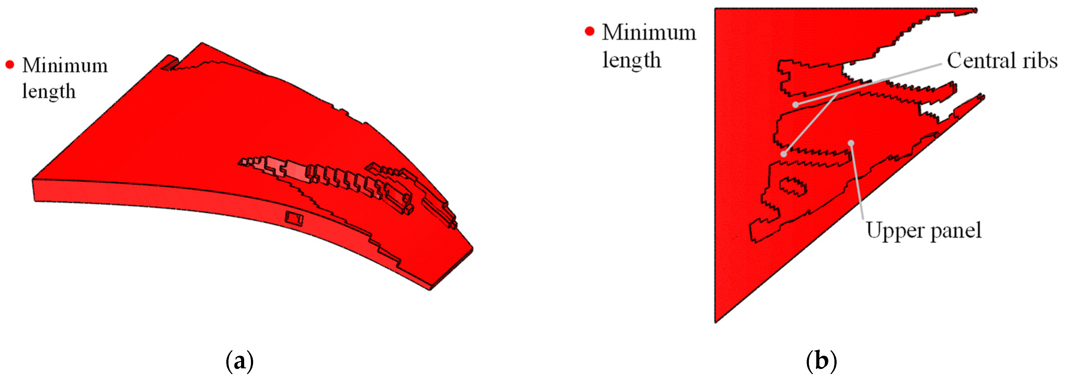
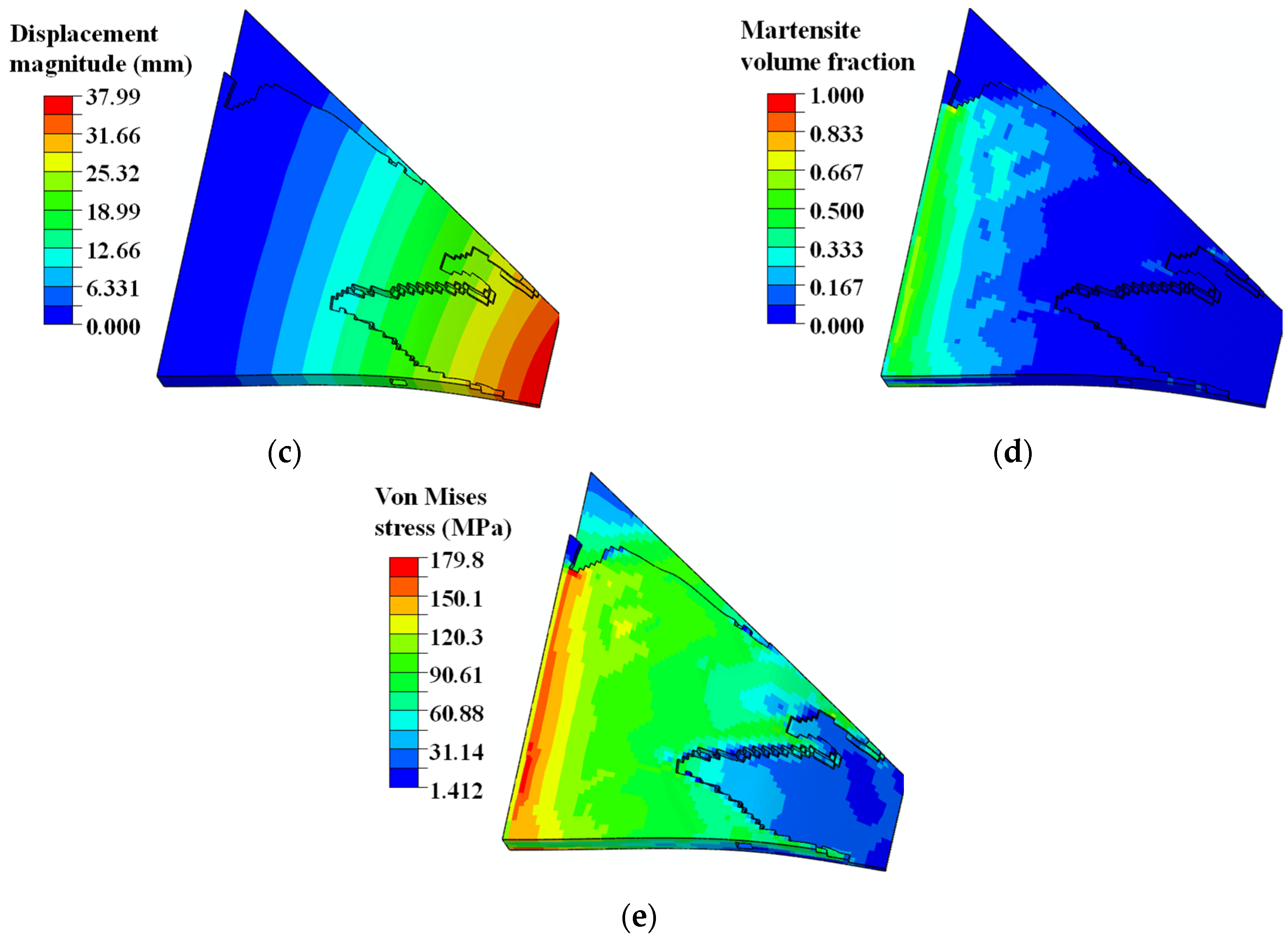
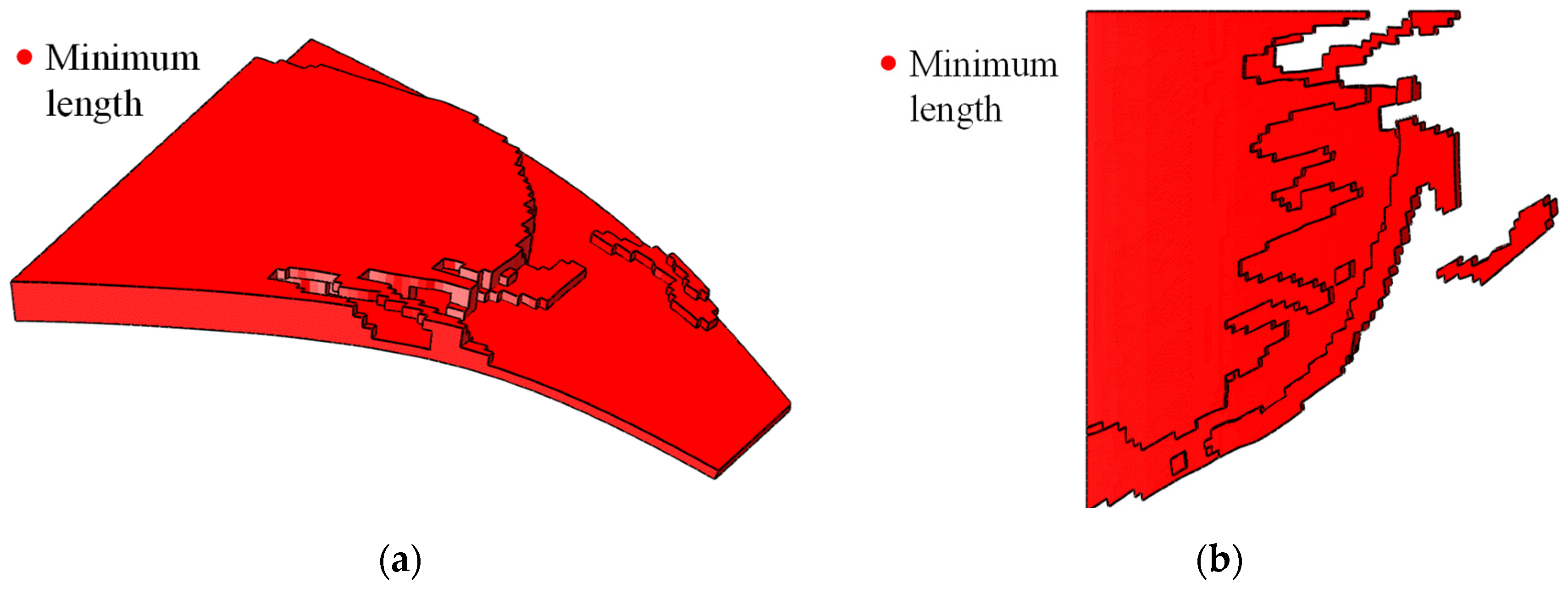
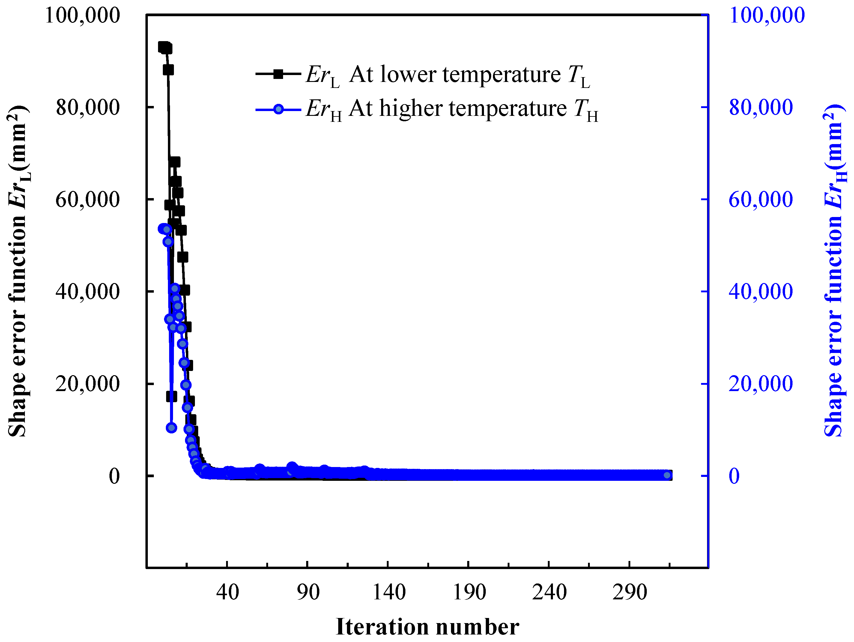
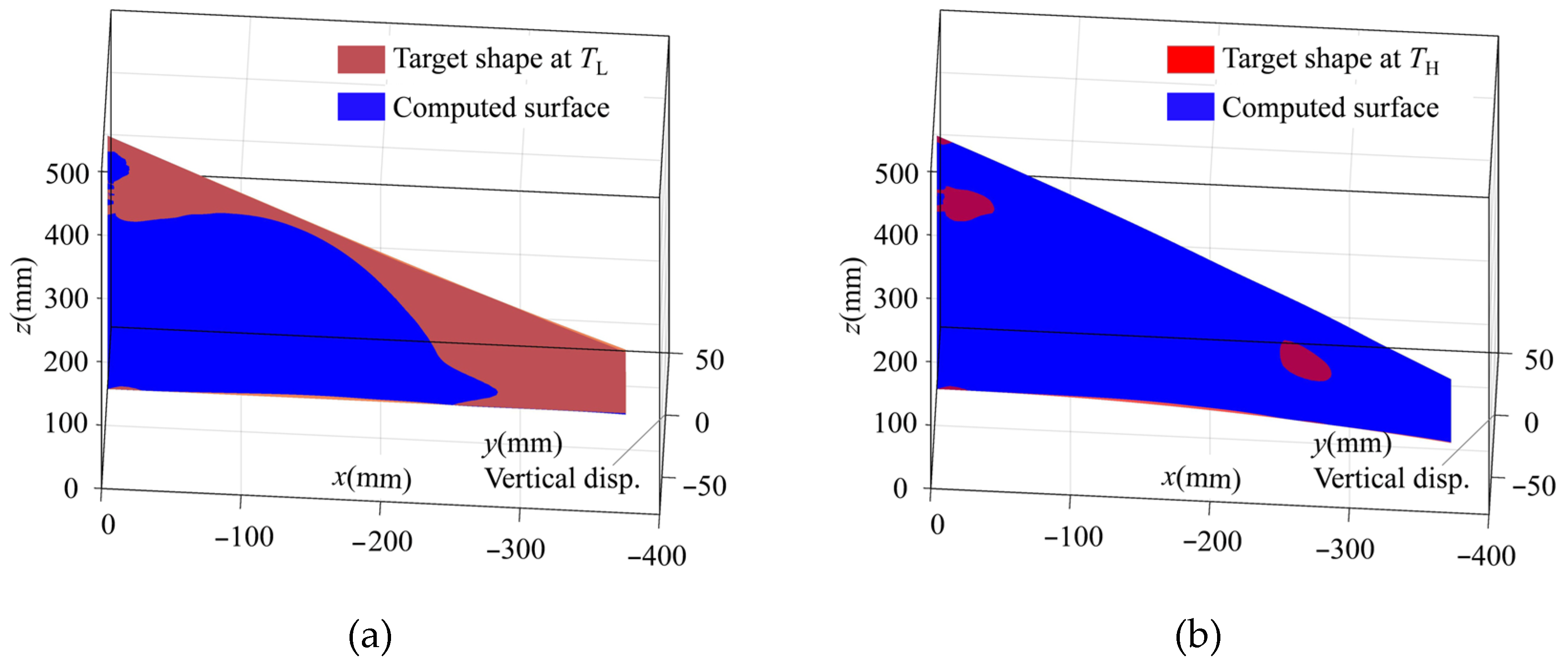
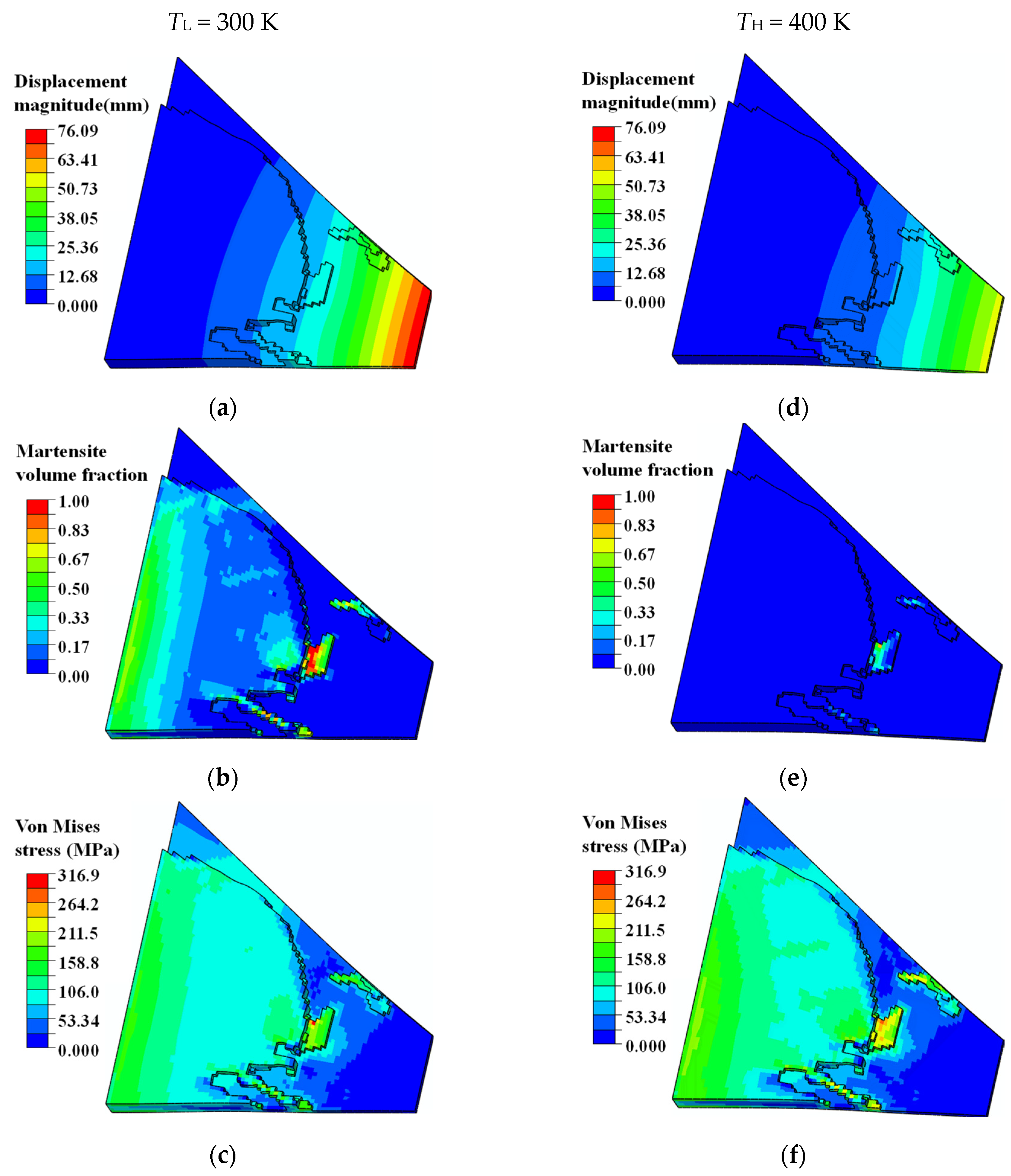
4.2. Topology Optimization of SMA Curved Wing for Prescribed Two-Way Shape Morphing

Here, an SMA curved wing design problem for prescribed two-way shape morphing was considered. The material parameters are listed in Table 3. The detailed geometric information of the curved wing structure is depicted in Figure 15. The curved wing structure was discretized with finite elements of averaged 5 mm length scale. A total of 15,556 3D solid finite elements with 60,375 nodes were generated. The upper-bound values δs and δv for geometric minimum length constraints were 9.0 × 10⁻⁵. The bottom surface of the curved wing structure was the non-design zone with uniform pressure load P = 0.4 N/mm2. Its thickness is 5 mm. A total of 80 observation points were selected according to Figure 15b. All the weighting factors are chosen as unit value 1. The density filter radius Rfilter = 10 was set as two times the average length of the finite elements.
From Figure 16a,b, we found that, for the SMA curved wing structure, with the compliance minimization design scheme, the central ribs were sandwiched with two side panels. This configuration enhanced the out-of-plane stiffness to the greatest extent, thus reducing the structural compliance. Based on the displacement contour in Figure 16c, the tip of the wing had a significant twisting geometric distortion while withstanding a uniform pressure load. The martensite volume fraction contour in Figure 16d shows that this design scheme minimized the austenite–martensite transformation region. The maximum Von Mises stress was about 180 MPa, as depicted in Figure 16e.
The upper-bound value δ for the shape error function ErH was set as 100 mm2. At material temperatures {TL, TH}, the expected geometric shapes of the bottom wing surface were defined as follows:
y L = 0.0 ; T L = 310 K
y H = 1 . 754 × 10 - 4 x 2 ;   T H = 400 K
Compared with the topology optimization results in Figure 16, the proposed topology optimization method, which considered plane–parabolic shape morphing, obtained different structural designs, as depicted in Figure 17. The enforcement structure was spatially distributed with span-wise, chord-wise ribs and material concentrations near the fixture. The whole topology-optimization process for the SMA wing structure took around 103 h. After 313 optimization iterations, the values of the shape error functions {ErL, ErH} decreased from {93,072.47 mm2, 53,608.01 mm2} to {120.30 mm2, 97.88 mm2}, only 0.13% and 0.18% of the initial values, respectively. Figure 18 shows that the topology-optimization process converged stably. The shape comparison in Figure 19 illustrates that the optimized SMA curved wing design precisely approached the prescribed plane and parabolic shapes under the conditions of pre-defined material temperatures and the constant pressure load. Below, detailed explanations of the topology-optimized design in Figure 17 are given with the simulation results in Figure 20.
According to the displacement contours in Figure 20a,d, this particular designed enforcement structure compensated for the imbalance of the curved wing geometry configuration and external pressure distribution, resulting in normalized and expected structural deformations. As shown in Figure 20b,e, stress-induced local martensite phase transformation facilitated the deformation of the curved wing structure into the expected plane shape at the material temperature TL. Assuming that the external pressure load was unchanged, the SMA wing bent into the target parabolic shape upon heating the structure to a higher material temperature TH. This was due to the transformation of detwinned martensite to austenite material phase, resulting in a reversible actuation deformation. Although the maximum martensite transformation strain was only 0.8%, the actuation displacement of the wing tip was about 22 mm, which was 1.1 times the total thickness of the curved wing structure.

5. Conclusions

This study aimed to resolve the automatic design problems of SMA actuators for prescribed two-way transforming shapes; we established a new topology-optimization formulation. To constrain the geometric distortions of SMA devices bearing external mechanical loads, the proposed topology optimization method formulated optimization criteria with desired target shapes instead of total structural compliance. When the topology-optimized SMA actuators withstood external mechanical loads, the key surfaces reached the desired two-way transforming shapes at the predefined material temperatures. Although the numerical examples demonstrated that minimizing both the shape error functions ErL and ErH was contradictory, feasible optimization results could be obtained for two-way shape-morphing designs by allowing reasonable tolerances. In this study, the macroscopic topology configurations of SMA were optimized to satisfy the desired shape morphing requirements. The simultaneous design of SMA macro material layouts and microstructures are expected to increase the availability of shape transformation mechanisms in future works.

Author Contributions

Conceptualization, K.Y. and J.H.; methodology, X.G.; software, Z.Y.; validation, W.M. and J.L.; writing—original draft preparation, K.Y. and J.L.; writing—review and editing, K.Y.; supervision, D.W.; project administration, Q.Y.; funding acquisition, K.Y. All authors have read and agreed to the published version of the manuscript.

Funding

This research was funded by National Key Research and Development Program of China (No. 2023YFB3406900), the Dean’s Fund of China Academy of Engineering Physics (No. YZJJ-10-01), National Natural Science Foundation of China (No. 12372123) and Youth Fund of the National Natural Science Foundation of China (No. 12102351).

Institutional Review Board Statement

Not applicable.

Informed Consent Statement

Not applicable.

Data Availability Statement

The data presented in this study are available on request from the corresponding author.

Conflicts of Interest

The authors declare no conflicts of interest.

References

  1. NASA to Test in-Flight Folding Spanwise Adaptive Wing to Enhance Aircraft Efficiency. Available online: https://www.nasa.gov/feature/nasa-to-test-in-flight-folding-spanwise-adaptive-wing-to-enhance-aircraft-efficiency (accessed on 14 October 2016).
  2. Shape Memory Alloy Technology Leads to Energy-Efficient CubeSat. Available online: https://engineering.unt.edu/news/shape-memory-alloy-technology-leads-energy-efficient-cubesathttps://engineering.unt.edu/news/shape-memory-alloy-technology-leads-energy-efficient-cubesat (accessed on 1 January 2019).
  3. 3D-Printed Structures “Remember” Their Shapes. Available online: https://news.mit.edu/2016/3-d-printed-structures-remember-shapes-drug-delivery-solar-panel-0826 (accessed on 26 August 2016).
  4. Breakthrough in Shape Memory Alloy 10 Million Bending Cycles before Failure. Available online: https://www.extremetech.com/extreme/207582-breakthrough-in-shape-memory-alloy-10-million-bending-cycles-before-failure (accessed on 9 June 2015).
  5. Hager, M.D.; Bode, S.; Weber, C.; Schubert, U.S. Shape memory polymers: Past, present and future developments. Prog. Polym. Sci. 2015, 49, 3–33. [Google Scholar] [CrossRef]
  6. Behl, M.; Lendlein, A. Shape-memory Polymers. Mater. Today 2007, 10, 20–28. [Google Scholar] [CrossRef]
  7. Zareie, S.; Issa, A.S.; Seethaler, R.J.; Zabihollah, A. Recent advances in the applications of shape memory alloys in civil infrastructures: A review. Structures 2020, 27, 1535–1550. [Google Scholar] [CrossRef]
  8. Qi, X.M.; Wang, E.L.; Dong, Y.B.; Fu, Y.Q. Research Progress of two-way shape memory polymer and its composites under stress-free condition. J. Zhejiang Sci-Tech Univ. 2019, 41, 300–307. [Google Scholar]
  9. Jani, J.M.; Leary, M.; Subic, A.; Gibson, M.A. A review of shape memory alloy research, applications and opportunities. Mater. Des. 2014, 56, 1078–1113. [Google Scholar] [CrossRef]
  10. Kang, Z.L.; James, K.A. Thermomechanical topology optimization of shape-memory alloy structures using a transient bilevel adjoint method. Int. J. Numer. Methods Eng. 2020, 121, 2558–2580. [Google Scholar] [CrossRef]
  11. Hartl, D.J.; Lagoudas, D.C.; Calkins, F.T.; Mabe, J.H. Use of a Ni60Ti shape memory alloy for active jet engine chevron application: II. Experimentally validated numerical analysis. Smart Mater. Struct. 2010, 19, 015021. [Google Scholar] [CrossRef]
  12. Khan, M.I.; Pequegnat, A.; Zhou, Y.N. Multiple memory shape memory alloys. Adv. Eng. Mater. 2013, 15, 386–393. [Google Scholar] [CrossRef]
  13. Li, P.Y.; Wang, Y.S.; Meng, F.Y.; Cao, L.; He, Z.R. Effect of heat treatment temperature on martensitic transformation and superelasticity of the Ti49Ni51 shape memory alloy. Materials 2019, 12, 2539. [Google Scholar] [CrossRef] [PubMed]
  14. Ansari, M.; Fahimi, P.; Baghani, M.; Golzar, M. An experimental investigation on training of NiTi-based shape memory alloys. Int. J. Appl. Mech. 2018, 10, 1850040. [Google Scholar] [CrossRef]
  15. Hartl, D.J.; Lagoudas, D.C. Aerospace applications of shape memory alloys. Proc. Inst. Mech. Eng.-Part G 2014, 221, 535–552. [Google Scholar] [CrossRef]
  16. Kudva, J.N. Overview of the DARPA Smart Wing Project. J. Intell. Mater. Syst. Struct. 2004, 15, 261–267. [Google Scholar] [CrossRef]
  17. Bil, C.; Massey, K.; Abdullah, E.J. Wing morphing control with shape memory alloy actuators. J. Intell. Mater. Syst. Struct. 2013, 24, 879–898. [Google Scholar] [CrossRef]
  18. Han, M.W.; Rodrigue, H.; Kim, H.I.; Song, S.H.; Ahn, S.H. Shape memory alloy/glass fiber woven composite for soft morphing winglets of unmanned aerial vehicles. Compos. Struct. 2016, 140, 202–212. [Google Scholar] [CrossRef]
  19. Zaki, W.; Moumni, Z. A three-dimensional model of the thermomechanical behavior of shape memory alloys. J. Mech. Phys. Solids 2007, 55, 2455–2490. [Google Scholar] [CrossRef]
  20. Kundu, A.; Banerjee, A. Coupled thermomechanical modelling of shape memory alloy structures undergoing large deformation. Int. J. Mech. Sci. 2022, 220, 107102. [Google Scholar] [CrossRef]
  21. Bouvet, C.; Calloch, S.; Lexcellent, C. A phenomenological model for pseudoelasticity of shape memory alloys under multiaxial proportional and nonproportional loadings. Eur. J. Mech.-A/Solids 2004, 23, 37–61. [Google Scholar] [CrossRef]
  22. Zhang, Y.H.; You, Y.J.; Moumni, Z.; Anlas, G.; Zhu, J.H.; Zhang, W.H. Experimental and theoretical investigation of the frequency effect on low cycle fatigue of shape memory alloys. Int. J. Plast. 2017, 90, 1–30. [Google Scholar] [CrossRef]
  23. Falk, F. Model free energy, mechanics, and thermodynamics of shape memory alloys. Acta Metall. 1980, 28, 1773–1780. [Google Scholar] [CrossRef]
  24. Zhang, Y.Q.; Jiang, S.Y.; Zhao, G.L.; Guo, K.R. Transformation yield surface of nanocrystalline NiTi shape memory alloy. Int. J. Mech. Sci. 2022, 222, 107102. [Google Scholar] [CrossRef]
  25. Tanaka, K.; Ohnami, D.; Watanabe, T.; Kosegawa, J. Micromechanical simulations of thermomechanical behavior in shape memory alloys: Transformation conditions and thermomechanical hystereses. Mech. Mater. 2002, 34, 279–298. [Google Scholar] [CrossRef]
  26. Thabuis, A.; Thomas, S.; Martinez, T.; Perriard, Y. Shape memory effect of benchmark compliant mechanisms designed with topology optimization. In Proceedings of the 2020 IEEE/ASME International Conference on Advanced Intelligent Mechatronics (AIM), Boston, MA, USA, 6–9 July 2020; pp. 571–576. [Google Scholar]
  27. Jovanova, J.; Frecker, M.; Hamilton, R.F.; Palmer, T.A. Target shape optimization of functionally graded shape memory alloy compliant mechanisms. J. Intell. Mater. Syst. Struct. 2019, 30, 1385–1396. [Google Scholar] [CrossRef]
  28. Gu, X.J.; Yang, K.K.; Wu, M.Q.; Zhang, Y.H.; Zhu, J.H.; Zhang, W.H. Integrated optimization design of smart morphing wing for accurate shape control. Chin. J. Aeronaut. 2021, 34, 135–147. [Google Scholar] [CrossRef]
  29. Bhattacharyya, A.; James, K.A. Topology optimization of shape memory polymer structures with programmable morphology. Struct. Multidiscip. Optim. 2021, 63, 1863–1887. [Google Scholar] [CrossRef]
  30. Langelaar, M.; Yoon, G.H.; Kim, Y.Y.; Keulen, F.V. Topology optimization of planar shape memory alloy thermal actuators using element connectivity parameterization. Int. J. Numer. Methods Eng. 2011, 88, 817–840. [Google Scholar] [CrossRef]
  31. Hou, J.; Wei, C.; Gu, X.J.; Zhu, J.H.; Zhang, W.H. Topology Optimization for Energy Dissipation Structures Based on Shape Memory Alloys. Struct. Multidiscip. Optim. 2023, 66, 55. [Google Scholar] [CrossRef]
  32. Kang, Z.; James, K. Multiphysics design of programmable shape-memory alloy-based smart structures via topology optimization. Struct. Multidiscip. Optim. 2022, 65, 24. [Google Scholar] [CrossRef]
  33. Farber, E.; Zhu, J.N.; Popovich, A.; Popovich, V. A review of NiTi shape memory alloy as a smart material produced by additive manufacturing. Mater. Today Proc. 2019, 30, 761–767. [Google Scholar] [CrossRef]
  34. Zhou, M.D.; Lazarov, B.S.; Wang, F.W.; Sigmund, O. Minimum length scale in topology optimization by geometric constraints. Comput. Methods Appl. Mech. Eng. 2015, 293, 266–282. [Google Scholar] [CrossRef]
  35. Ball, J.M.; James, R.D. Fine phase mixtures as minimizers of energy. Arch. Ration. Mech. Anal. 1987, 100, 13–52. [Google Scholar] [CrossRef]
  36. Gu, X.J.; Zaki, W.; Morin, C.; Moumni, Z.; Zhang, W.H. Time integration and assessment of a model for shape memory alloys considering multiaxial nonproportional loading cases. Int. J. Solids Struct. 2014, 54, 82–99. [Google Scholar] [CrossRef]
  37. Shaw, J.A.; Kyriakides, S. Thermomechanical aspects of NiTi. J. Mech. Phys. Solids 1995, 43, 1243–1281. [Google Scholar] [CrossRef]
  38. Sigmund, O. A 99 line topology optimization code written in MATLAB. Struct. Multidiscip. Optim. 2001, 21, 120–127. [Google Scholar] [CrossRef]
  39. Andreassen, E.; Clausen, A.; Schevenels, M.; Lazarov, B.S.; Sigmund, O. Efficient topology optimization in MATLAB using 88 lines of code. Struct. Multidiscip. Optim. 2011, 43, 1–16. [Google Scholar] [CrossRef]
  40. Wang, F.W.; Lazarov, B.S.; Sigmund, O. On projection methods, convergence and robust formulations in topology optimization. Struct. Multidiscip. Optim. 2011, 43, 767–784. [Google Scholar] [CrossRef]
  41. Hou, J.; Gu, X.J.; Zhu, J.H.; Wang, J.; Zhang, W.H. Topology optimization of joint load control with geometrical nonlinearity. Chin. J. Aeronaut. 2020, 33, 372–382. [Google Scholar] [CrossRef]
  42. Yang, K.K.; Fernandez, E.; Niu, C.; Duysinx, P.; Zhu, J.H.; Zhang, W.H. Note on spatial gradient operators and gradient-based minimum length constraints in SIMP topology optimization. Struct. Multidiscip. Optim. 2019, 60, 393–400. [Google Scholar] [CrossRef]
  43. Svanberg, K. A globally convergent version of MMA without linesearch. In Proceedings of the Proceedings of the First World Congress of Structural and Multidisciplinary Optimization, Goslar, Germany, 28 May–2 June 1995; pp. 9–16.
  44. Buhl, T.; Pedersen, C.B.W.; Sigmund, O. Stiffness design of geometrically nonlinear structures using topology optimization. Struct. Multidiscip. Optim. 2000, 19, 93–104. [Google Scholar] [CrossRef]
  45. Luo, Y.J.; Wang, M.Y.; Kang, Z. Topology optimization of geometrically nonlinear structures based on an additive hyperelasticity technique. Comput. Methods Appl. Mech. Eng. 2015, 286, 422–441. [Google Scholar] [CrossRef]
  46. Wang, F.W.; Lazarov, B.S.; Sigmund, O.; Jensen, J.S. Interpolation scheme for fictitious domain techniques and topology optimization of finite strain elastic problems. Comput. Methods Appl. Mech. Eng. 2014, 276, 453–472. [Google Scholar] [CrossRef]
  47. Zienkiewicz, O.C.; Taylor, R.L.; Fox, D. The Finite Element Method for Solid and Structural Mechanics, 7th ed.; Butterworth-Heinemann: Oxford, UK; Elsevier: Amsterdam, The Netherlands, 2013. [Google Scholar]
Figure 1. Applications of shape memory materials as well as structures: (a) spanwise adaptive wing using SMA actuator [1]; (b) deploying solar panels by SMA mechanism [2]; (c) soft gripper printed by SMP, and (d) SMA arterial stent [4].
Actuators 13 00065 g001
Figure 2. Stress–temperature diagram of SMA materials.
Actuators 13 00065 g002
Figure 3. The interpolated SMA material constitutive curves and corresponding physical densities.
Actuators 13 00065 g003
Figure 4. Definition of the shape error function.
Actuators 13 00065 g004
Figure 5. Illustration for super element definition and finite element treatment.
Actuators 13 00065 g005
Figure 6. Flowchart for topology optimization of two-way shape-morphing SMA actuators.
Actuators 13 00065 g006
Figure 7. Geometric configuration and boundary conditions of SMA cantilever beam (thickness of cantilever beam: 8 mm).
Actuators 13 00065 g007
Figure 8. Topological designs of SMA cantilever beam at (a) Iteration 20, (b) Iteration 100, (c) Iteration 240, and (d) Iteration 430 (final design).
Actuators 13 00065 g008aActuators 13 00065 g008b
Figure 9. Shape error iteration history of two-way shape morphing design for SMA cantilever beam.
Actuators 13 00065 g009
Figure 10. Simulated deformation, phase transformation, and structural stress contours of optimized SMA cantilever at different material temperatures. TL = 300 K. (a) Vertical displacement contour (Min: −98.34 mm). (b) Martensite volume fraction z contour (max: 1.0). (c) Von Mises stress contour (max: 941.10 MPa). TH = 400 K. (d) Vertical displacement contour (Min: −53.63 mm). (e) Martensite volume fraction z contour (max: 0.36). (f) Von Mises stress contour (max: 737.30 MPa).
Actuators 13 00065 g010
Figure 11. Constitutive behaviors of SMA material in different transformation zones.
Actuators 13 00065 g011
Figure 12. Minimizing compliance design of SMA cantilever beam (T = 300 K). (a) Optimized topology configuration. Simulation contours of (b) vertical displacement (Min: −51.91 mm), (c) martensite volume fraction z (max: 0.49), and (d) Von Mises stress (max: 379.50 MPa).
Actuators 13 00065 g012
Figure 13. Iteration history for minimizing compliance design of SMA cantilever beam.
Actuators 13 00065 g013
Figure 14. Relationship between shape error values of ErH and ErL for optimized SMA cantilever beams.
Actuators 13 00065 g014
Figure 15. Illustrations of SMA curved wing structure design problem from (a) axonometric view, (b) bottom view, and (c) front view.
Actuators 13 00065 g015aActuators 13 00065 g015b
Figure 16. Minimizing compliance design of SMA curved wing structure. Topology-optimized design from (a) axonometric view (depicted with non-design zone) and (b) bottom view (depicted without non-design zone). Simulation contours of (c) displacement magnitude (max: 37.99 mm), (d) martensite volume fraction z (max: 0.76), and (e) Von Mises stress (max: 179.80 MPa).
Actuators 13 00065 g016aActuators 13 00065 g016b
Figure 17. Topology-optimized curved wing design for prescribed two-way shape morphing from (a) axonometric view (depicted with non-design domain) and (b) bottom view (depicted without non-design domain).
Actuators 13 00065 g017
Figure 18. Topology optimization iteration history of SMA curved wing structure.
Actuators 13 00065 g018
Figure 19. Comparison between computed shape and desired target shape of curved wing structure at (a) material temperature TL and (b) material temperature TH.
Actuators 13 00065 g019
Figure 20. Simulated deformation, phase transformation, and structural stress contours of optimized SMA curved wing structure at different material temperatures. For TL = 310 K: (a) displacement contour (max: 76.09 mm), (b) martensite volume fraction z contour (max: 1.0), and (c) Von Mises stress contour (max: 316.90 MPa). For TH = 400 K: (d) displacement contour (max: 54.08 mm), (e) martensite volume fraction z contour (max:0.77), and (f) Von Mises stress (max: 284.20 MPa).
Actuators 13 00065 g020
Table 1. Parameter values using data from Shaw and Kyriakides [37].
Material Parameter Material Parameter
CA61,500 MPaa6.8920 MPa
CM24,000 MPab6.9091 MPa
v0.3ε04%
Y110 MPaG4.6556 MPa
αs2750 MPaβs5500 MPa
ξs0.4381 MPa/°Ck2.4920 MPa
Af040 °CTMaterial temperature
Table 3. SMA material parameters [21].
Material Parameter Material Parameter
CA45,200 MPaa0.24 MPa
CM26,400 MPab0.096 MPa
v0.3ε00.8%
Y30 MPaG1.92 MPa
αs2500 MPaβs6250 MPa
ξs0.0145 MPa/Kκ0.038 MPa
A0f300 KTMaterial temperature
Table 2. Material parameters of SMA from the work of Gu et al. [36].
Material Parameter Material Parameter
CA30,340 MPaa5.16 MPa
CM18,000 MPab6.36 MPa
v0.3ε04%
Y30 MPaG13.17 MPa
αs500 MPaβs1250 MPa
ξs0.2 MPa/Kκ4.16 MPa
A0f300 KTMaterial temperature
Disclaimer/Publisher’s Note: The statements, opinions and data contained in all publications are solely those of the individual author(s) and contributor(s) and not of MDPI and/or the editor(s). MDPI and/or the editor(s) disclaim responsibility for any injury to people or property resulting from any ideas, methods, instructions or products referred to in the content.

