Article

Research on Mechanical Leg Structure Design and Control System of Lower Limb Exoskeleton Rehabilitation Robot Based on Magnetorheological Variable Stiffness and Damping Actuator

1
School of Mechanical and Marine Engineering, Beibu Gulf University, Qinzhou 535011, China
2
Department of Integrated Systems Engineering, Nagasaki Institute of Applied Science, Nagasaki 851-0193, Japan
3
Advanced Science and Technology Research Institute, Beibu Gulf University, Qinzhou 535001, China
4
CATARC (Tianjin) Automotive Engineering Research Institute Co., Ltd., Tianjin 300300, China
5
Research Institute for Integrated Science, Kanagawa University, Yokohama, Tokyo 259-1293, Japan
*
Authors to whom correspondence should be addressed.
Actuators 2024, 13(4), 132; https://doi.org/10.3390/act13040132
Submission received: 1 March 2024 / Revised: 25 March 2024 / Accepted: 3 April 2024 / Published: 5 April 2024
(This article belongs to the Special Issue Soft Actuators for Medical Robotics)

Abstract

:
During the walking process of lower limb exoskeleton rehabilitation robots, inevitable collision impacts will occur when the swinging leg lands on the ground. The impact reaction force from the ground will induce vibrations in the entire robot’s body from bottom to top. To address this phenomenon, considering the limitations of traditional active compliance and passive compliance methods, a variable stiffness and damping actuator (VSDA) leg structure using a magnetorheological damper (MRD) is proposed. Firstly, experimental methods are used to obtain the ground reaction force (GRF) exerted on a normal person during walking. Then, a mathematical model of the VSDA leg structure is constructed, and its working principle is analyzed. Based on human mass and dimensions, a 3D model is designed and selected. Finally, a simulation model is built in the MATLAB/Simulink environment using the fuzzy switch damping control strategy to simulate the acceleration and displacement of the human body under sinusoidal and random excitations. The results indicate that under sinusoidal excitation, employing fuzzy switch damping control optimizes human displacement by 72.47% compared to the high stiffness and high damping system, and by 16.95% compared to the switch damping system. Human acceleration is optimized by 52.09% compared to the high stiffness and high damping system, and by 25.2% compared to the switch damping system. Under random excitation, adopting fuzzy switch damping control optimizes human displacement by 59.09% compared to the high stiffness and high damping system, and by 21.74% compared to the switch damping system. Human acceleration is optimized by 78.74% compared to the high stiffness and high damping system, and by 31.66% compared to the switch damping system. This validates the VSDA design structure and control method, demonstrating certain advantages in improving the compliance and stability of lower limb exoskeleton rehabilitation robots.

1. Introduction

As an assistive device, the lower limb exoskeleton rehabilitation robot primarily aids individuals recovering walking ability due to lower limb injuries or impairments. The robot requires personalized adjustments based on the wearer’s needs and progress to assist them in gradually regaining muscle strength, balance, and gait control. While joints and muscles provide cushioning when walking, running, or experiencing external impacts, unavoidable collisions occur between the swinging leg and the ground during robot locomotion [1]. The impact reaction force from the ground induces vibrations from the bottom to the top of the robot’s body. Moreover, as walking speed and stride length increase, both ground impact and upper-body vibrations become more pronounced. Therefore, reducing impacts during robot locomotion is crucial for improving stability, energy efficiency, accuracy, and comfort.
To overcome the impact of ground forces on both the robot and the wearer and imbue the robot with compliant characteristics, researchers have proposed active compliant control methods, primarily through various control algorithms to manage external forces. The active compliant interaction control scheme, based on impedance parameter adaptive adjustment, is widely employed in lower limb exoskeleton rehabilitation robots [2,3,4,5]. This scheme adjusts the robot’s motion based on the difference between the desired force or torque and the perceived force or torque. Additionally, mathematical models can describe the dynamics and kinematic characteristics of the robot system, enabling the design of control algorithms to optimize the robot’s motion trajectory [6]. Furthermore, control algorithms designed to mimic the functioning of the human nervous system achieve precise control over the robot. Neural network control methods typically combine sensor feedback and model prediction to achieve efficient motion control [7,8,9]. In addition to active control methods, passive compliance of the robot can be achieved through the introduction of stiffness and damping structures. For instance, series elastic actuators (SEAs) introduce flexibility in control and motion by incorporating elastic elements, usually springs, between the motor and the load [10]. In recent years, variable stiffness actuators (VSAs) have emerged as a research hotspot to overcome the limitations of fixed stiffness. Various structures can achieve variable stiffness characteristics [11,12,13]. However, analysis of the above research reveals that active compliant controllers heavily rely on precise dynamic models of the actual robot leg structure. For robots with complex leg structures, this poses a major challenge in achieving active compliance. Moreover, the stiffness and damping coefficients of passive compliant structures are often fixed values, making it difficult to adapt to different ground conditions.
In recent years, magnetorheological (MR) technology has become increasingly mature. Magnetorheological dampers (MRDs) are devices that utilize the rheological properties of magnetorheological fluids to achieve damping regulation. When an external magnetic field is applied, the particles of the magnetorheological fluid undergo rearrangement, altering its flow properties and generating damping effects within the device. Currently, MRDs are widely used in automotive suspension systems, allowing for the adjustment of suspension stiffness and damping effects according to different road conditions and driving requirements [14,15,16]. Moreover, MRDs find extensive applications in various fields such as buildings, bridges, etc. [17,18]. Furthermore, in the field of robotics, MRDs can be employed to enhance motion control and stability, and reduce vibration and impact. They have been utilized in mechanical arms, bionic legs, bionic joints, smart prosthetics, and other applications [19,20,21,22]. In terms of control strategies, semiactive control [23,24] and Skyhook damping control [25] are commonly applied.
The human calf plays a crucial role in supporting, moving, balancing, and motion control. The muscle–tendon complex of the leg can absorb, store, and dissipate a significant amount of energy generated by impacts, thereby reducing the impact on the body. Addressing the shortcomings of both active and passive compliance, this study combines the advantages of MRDs with the characteristics of human calf muscles. Based on experimental data of the ground reaction force (GRF) curve in the vertical direction during human walking, the lower limb exoskeleton rehabilitation robot’s calf is simplified into a single-degree-of-freedom vibration model. A novel structure for the lower limb exoskeleton rehabilitation robot’s calf is designed, incorporating two MRDs and two springs to achieve real-time adjustment of joint stiffness and damping. The three-dimensional model design of the VSDA is completed using Solidworks modeling software version 2021, and the characteristics of the MRDs are analyzed and selected. In terms of control strategy, based on traditional Skyhook damping control, a switch damping control algorithm is designed and integrated with the fuzzy control theory from modern control theory. Simulation analysis is conducted on the MATLAB/Simulink platform to validate the improvement in body displacement and acceleration when employing fuzzy switch damping control under sinusoidal or random excitations. The results indicate that this control strategy offers certain advantages in enhancing the compliance and stability of the lower limb exoskeleton rehabilitation robot.

2. Background

In our previous research, a lower limb exoskeleton robot designed for rehabilitation purposes was developed. The three-dimensional model of the robot is illustrated in Figure 1. The emphasis of this study was on the hip and knee joints of the robot. A novel actuator, the Series Elastic Damper Actuator (SEDA) [26], was designed, and the impact of elastic and damping coefficients on the system was analyzed. To address the control issues related to the output force of the SEDA, fuzzy control was introduced based on the traditional PID control algorithm, and simulation analysis was conducted using the MATLAB/Simulink platform. Compared to the active joints of the hip and knee, the ankle joint serves as a passive joint and does not require a power source. However, during normal walking, when the foot contacts the ground, the ground exerts an upward reaction force on the foot. This force is transmitted to the calf, and its magnitude depends on the force exerted on the ground and the hardness of the ground. In this process, the muscles and ligaments of the calf play a crucial role in controlling gait and protecting the joints. These muscles and ligaments absorb and alleviate the impact force from the ground during walking, thereby reducing the burden on the calf bones. Therefore, the design of the robot calf needs to mitigate this impact force to enhance the wearer’s comfort.
We conducted experiments to measure the G experienced by normal individuals during walking. The experiments utilized the Quanser Optitrack optical three-dimensional motion capture system with a sampling frequency of 100 Hz. Six FLEX 3 infrared cameras were employed for spatial three-dimensional localization, along with an array of distributed flexible thin-film plantar pressure sensors, as shown in Figure 2a. These sensors feature a 6-row by 4-column array design, comprising 18 independent sensing elements to minimize mutual interference. Motive data analysis software version 2.0.0 was utilized for data processing. We selected five healthy participants for the experiment, with the following specifications: age: 22 ± 3 years old; weight: 60 ± 20 kg; height: 170 ± 10 cm; foot length: 250 ± 15 mm. Prior to the experiment, the participant was thoroughly briefed on the purpose, methods, and potential risks of the experiment. Additionally, detailed instructions regarding the experimental tasks were provided. Walking was chosen as the fundamental motion pattern, with a flat surface serving as the basic constraint. Based on the characteristics of muscle activity groups during human walking and the passive infrared optical reflection principle, seventeen marker points were nonlinearly and asymmetrically attached to the lower limbs, as illustrated in Figure 2b.
After multiple repeated experiments, the vertical GRF curve during human walking was obtained, as shown in Figure 3. From the graph, it is evident that during walking, there are two distinct peaks. The first peak occurs when the foot touches the ground, with the GRF exceeding the body weight. As the body’s center of gravity crosses the line of gravity, the weight transfers to the contralateral lower limb, leading to a decrease in GRF to its minimum point as the contralateral lower limb first contacts the ground and enters the stance phase. Subsequently, due to the push-off force, the GRF increases, resulting in the second peak, which is similar in magnitude to the first peak. Finally, as the foot leaves the ground, the body enters the swing phase, and the GRF decreases to approximately 0 N. At the same time, through observation, it can be seen that the ground reaction force received is approximately 1.4 times the body weight.

3. Variable Stiffness and Damping Actuator (VSDA) Design

3.1. Mathematical Model of VSDA

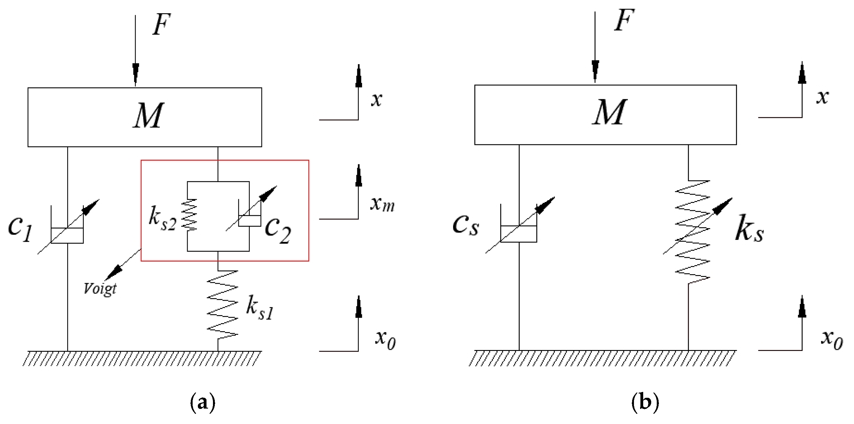
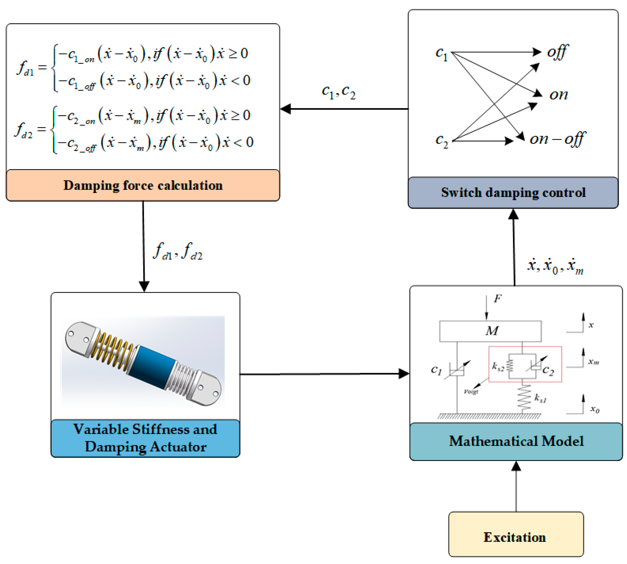
We can simplify the calf of the lower limb exoskeleton rehabilitation robot into a single-degree-of-freedom vibration model, as shown in Figure 4a. This structure, unlike traditional robot calves, not only avoids the impact of pure rigid body structures but also adds a Vogit unit to the existing spring and damping structure. The Vogit unit, composed of a spring and damping in parallel, is then connected in series with the original spring, enabling simultaneous adjustment of the stiffness and damping of the robot calf. The VSDA model consist of two controllable damping MRDs and two fixed-stiffness coil springs. The MRD c2 and coil spring ks2 are connected in parallel to form the Vogit unit, which is then connected in series with the coil spring ks1. Subsequently, the Vogit unit is connected in parallel with the MRD c1. Here, M represents the mass of the human body, F denotes the excitation force applied by the human to the VSDA, x is the displacement of the human body, xm indicates the displacement of the VSDA, and x0 represents the displacement of the ground.
Based on Newton’s second law and vibration theory, the motion differential equation for the model shown in Figure 4a can be established as follows:
M x ¨ = F c 1 x ˙ x ˙ 0 c 2 x ˙ x ˙ m k s 2 x x m
c 2 x ˙ x ˙ m + k s 2 x x m = k s 1 x m x 0
In the above equation, x ˙ , x ˙ m , and x ˙ 0 represent the velocities of the person, the variable stiffness and damping actuator, and the ground, respectively. x ¨ denotes the acceleration of the person.
When considering only ground excitation, i.e., F = 0, with input consisting of ground input displacement and ground excitation velocity, and output consisting of vertical acceleration and displacement of the human body, by applying Laplace transform to Equations (1) and (2), we can obtain the transfer function between the displacement of the human body and the displacement of the ground as follows:
G 1 ( s ) = X s X 0 s = c 1 c 2 s 2 + k s 1 c 1 + k s 2 c 1 + k s 1 c 2 s + k s 1 k s 2 M c 2 s 3 + M k s 1 + M k s 2 + c 1 c 2 s 2 + k s 1 c 1 + k s 2 c 1 + k s 1 c 2 s + k s 1 k s 2
The transfer function between the acceleration of the human body and the velocity of the ground is given by
H 1 ( s ) = X ¨ s X 0 ˙ s = c 1 c 2 s 3 + k s 1 c 1 + k s 2 c 1 + k s 1 c 2 s 2 + k s 1 k s 2 s M c 2 s 3 + M k s 1 + M k s 2 + c 1 c 2 s 2 + k s 1 c 1 + k s 2 c 1 + k s 1 c 2 s + k s 1 k s 2
When considering only the force excitation on the human body, i.e., x 0 = 0, by applying Laplace transform to Equations (1) and (2), we can obtain the transfer function between the displacement of the human body and the input force as follows:
G 2 ( s ) = X s F s = k s 1 + k s 2 + c 2 s M c 2 s 3 + M k s 1 + M k s 2 + c 1 c 2 s 2 + k s 1 c 1 + k s 2 c 1 + k s 1 c 2 s + k s 1 k s 2
The transfer function between the acceleration of the human body and the input force is given by
H 2 ( s ) = X ¨ s F s = c 2 s 3 + k s 1 s 2 + k s 2 s 2 M c 2 s 3 + M k s 1 + M k s 2 + c 1 c 2 s 2 + k s 1 c 1 + k s 2 c 1 + k s 1 c 2 s + k s 1 k s 2
Substituting s = into Equations (3) and (5), we can obtain
G 1 ( j ω ) = X j ω X 0 j ω = c 1 c 2 ω 2 + j k s 1 c 1 + k s 2 c 1 + k s 1 c 2 ω + k s 1 k s 2 M k s 1 + M k s 2 + c 1 c 2 ω 2 j k s 1 c 1 + k s 2 c 1 + k s 1 c 2 M c 2 ω 2 ω + k s 1 k s 2
G 2 ( j ω ) = X j ω F j ω = k s 1 + k s 2 + j c 2 ω M k s 1 + M k s 2 + c 1 c 2 ω 2 j k s 1 c 1 + k s 2 c 1 + k s 1 c 2 M c 2 ω 2 ω + k s 1 k s 2
Figure 4b represents a simplified version of Figure 4a, corresponding to its equivalent model. Similarly, based on Newton’s second law and vibration theory, the motion differential equation for the equivalent model shown in Figure 4b can be established as follows:
M x ¨ = F c s x ˙ x ˙ 0 k s x x 0
In the equation, c s and k s represent the equivalent damping coefficient and equivalent stiffness coefficient of the VSDA, respectively.
Similarly, when considering only ground excitation, i.e., F = 0, by applying Laplace transform to Equation (9), we can obtain the transfer function of the human body displacement as follows:
G 3 ( s ) = X s X 0 s = c s s + k s M s 2 + c s s + k s
When considering only force excitation on the human body, i.e., x 0 = 0, by applying Laplace transform to Equation (9), we can obtain the transfer function between the human body displacement and the force as follows:
G 4 ( s ) = X s F s = 1 M s 2 + c s s + k s
Substituting s = into Equations (10) and (11), we can obtain
G 3 ( j ω ) = X j ω X 0 j ω = j c s ω + k s M ω 2 + j c s ω + k s
G 4 ( j ω ) = X j ω F j ω = 1 M ω 2 + j c s ω + k s
By comparing Equations (5) and (6) with Equations (10) and (11), we can derive the expressions for the equivalent stiffness coefficient and equivalent damping coefficient corresponding to the equivalent model of the variable stiffness and damping actuator as follows:
k s = k s 1 k s 1 2 ( k s 1 + k s 2 ) ( k s 1 + k s 2 ) 2 + c 2 2 ω 2
c s = c 1 + k s 1 2 c 2 ( k s 1 + k s 2 ) 2 + c 2 2 ω 2
From the expression of the equivalent stiffness coefficient (12), it can be observed that the value of k s is related to the MRD c2 and is independent of MRD c1. The effective stiffness of the system can be adjusted by the MRD c2. When c2 tends to infinity, the equivalent stiffness k s is equivalent to the stiffness of the series connection of k s 1 and k s 2 , i.e., k s = k s 1 k s 2 / k s 1 + k s 2 ; when c2 tends to zero, the equivalent stiffness k s is equivalent to the stiffness of the spring k s 1 , i.e., k s = k s 1 . Thus, the variable stiffness range of the entire system is [ k s 1 k s 2 / k s 1 + k s 2 , k s 1 ]. From the expression of the equivalent damping coefficient (13), it can be seen that when c2 tends to infinity, c s = c1; when c2 gradually approaches infinity from zero, c s first increases and then decreases, but it always remains greater than c1. Hence, although the change in the equivalent damping coefficient c s is achieved jointly by the MRDs c 1 and c2, c1 actually plays a decisive role in the variation of c s .

3.2. Design of VSDA Structure

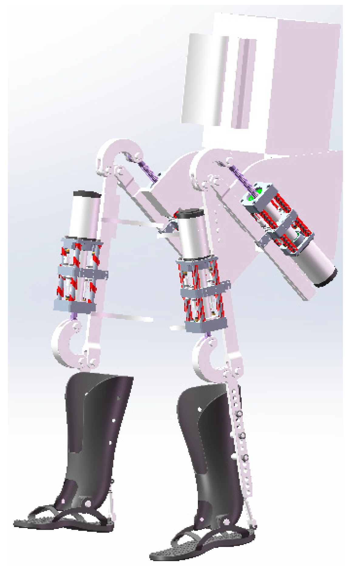
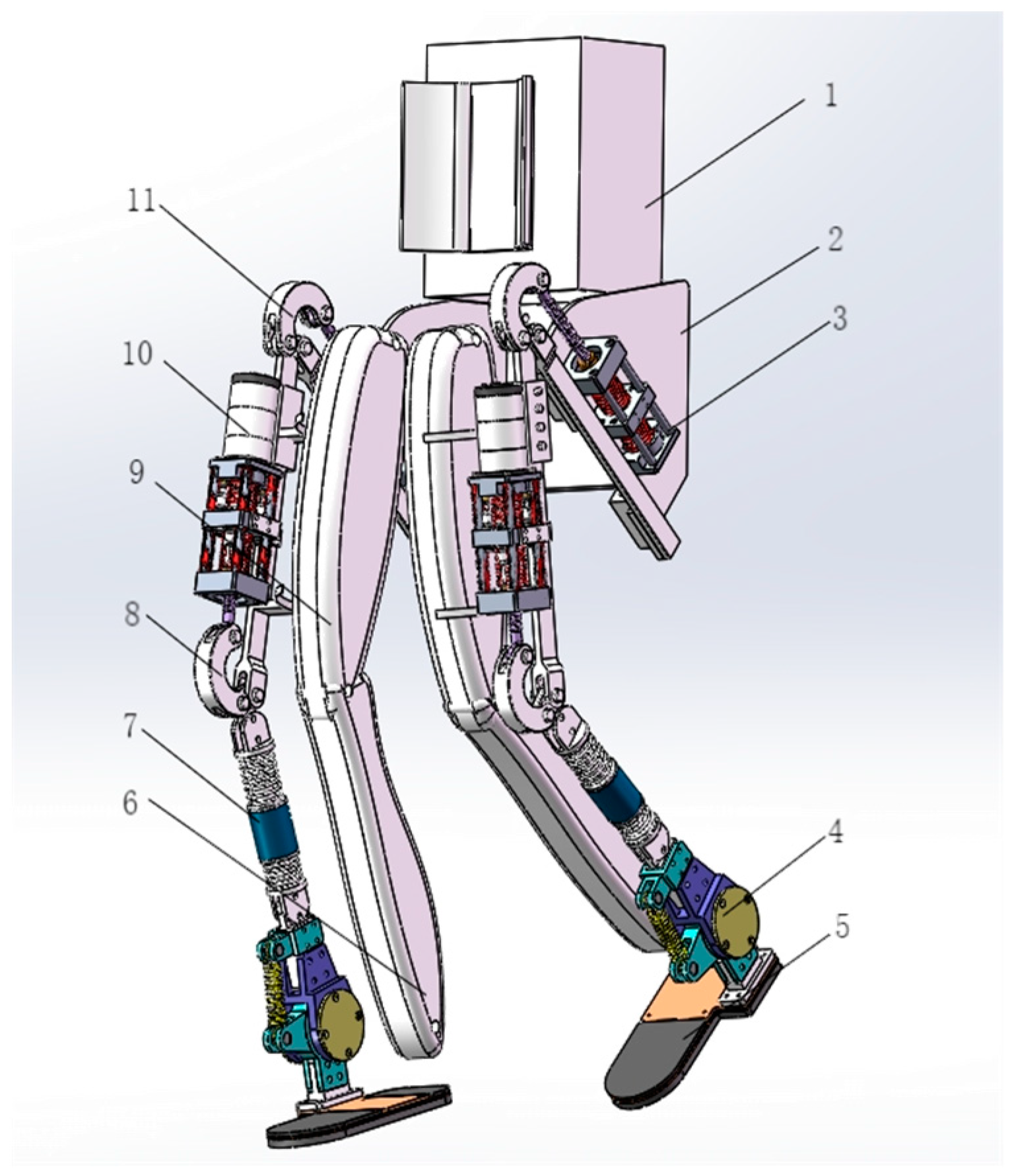
The design of lower limb exoskeleton rehabilitation robots needs to mimic the natural movements of the human lower limbs and provide necessary assistance when needed. Therefore, the structural design needs to consider the degrees of freedom of the knee joint, hip joint, and ankle joint, and ensure that the robot can provide sufficient range and flexibility. The overall structure of the lower limb exoskeleton rehabilitation robot is shown in Figure 5.
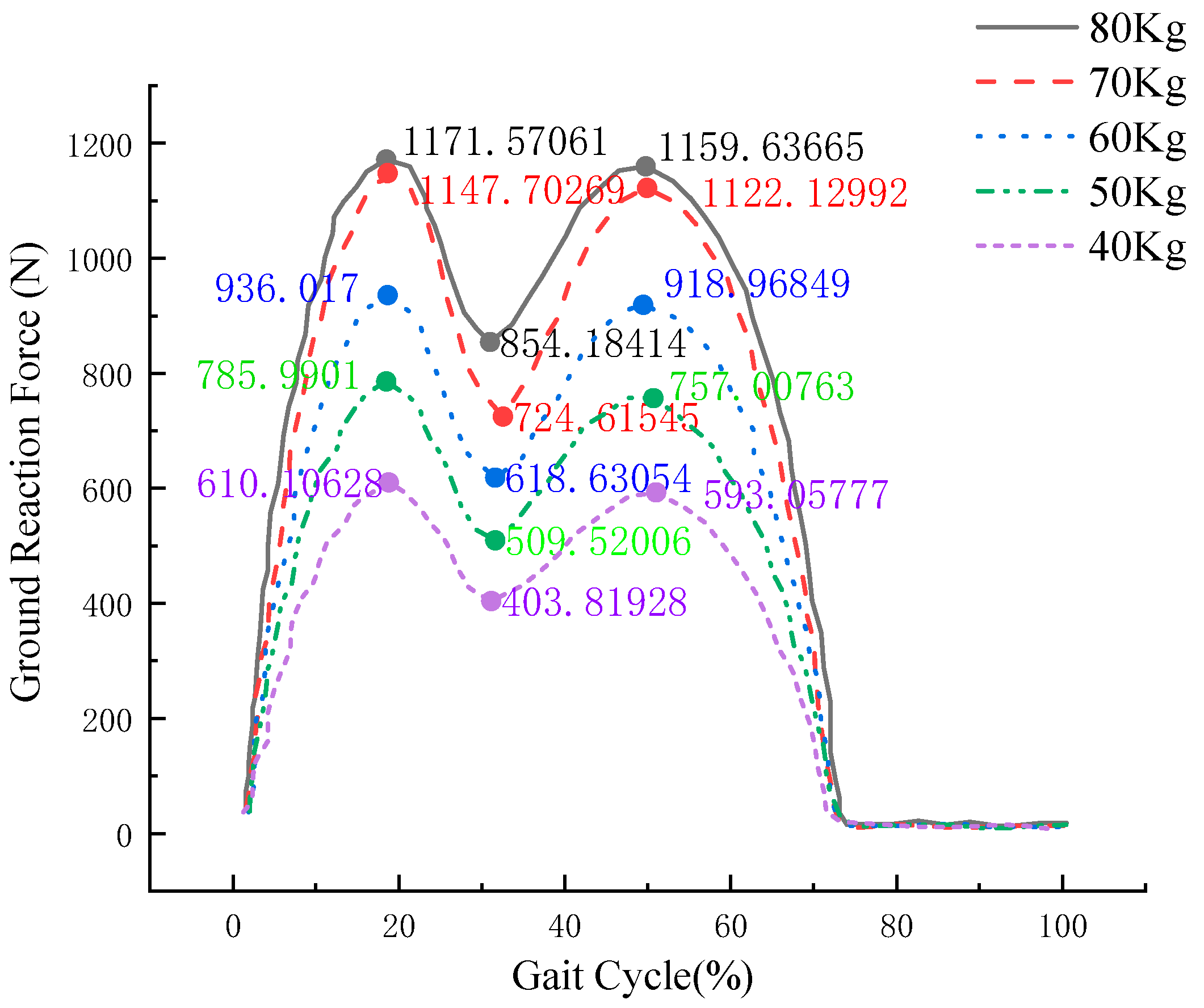
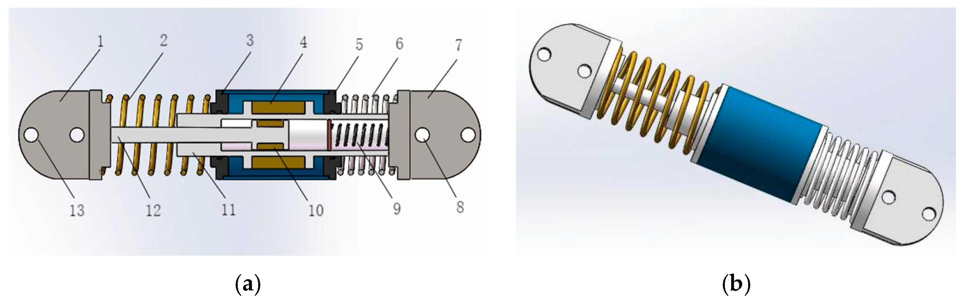
Through our previous research, we demonstrated that increasing the stiffness coefficient enhances the system’s impact resistance. However, it also leads to a larger output bandwidth and output impedance value, resulting in a near-rigid connection between the actuator and the load, consequently weakening the system’s stability. Conversely, increasing the damping coefficient improves system stability, but higher damping coefficients reduce the wearer’s comfort when using the exoskeleton. Based on the design of the overall structure of the lower limb exoskeleton rehabilitation robot and considering the human gait GRF curve obtained from previous experiments, the maximum ground reaction force experienced is approximately 1.4 times the body weight. To meet the usage requirements of a broader range of wearers, the variable stiffness and damping actuator should withstand a higher maximum pressure. This helps prevent the occurrence of the spring bottoming out, which could potentially harm the wearer. However, while meeting the maximum pressure requirement, the flexibility of walking should also be considered. Therefore, it is essential to select optimal parameters that match the human body. This paper primarily analyzes the variable stiffness and damping actuator of the calf, as shown in Figure 6.
From the above diagram, it can be observed that the VSDA mainly consists of two MRDs with different damping coefficients and two springs with different stiffness coefficients. MRD-1 primarily comprises an upper connector, a lower connector, a piston rod, seal rings, an energy storage spring, electromagnetic coils, and magnetorheological fluid. The upper connector primarily links to the knee joint, while the lower connector connects to the ankle joint. Both connectors feature length-adjustment holes to accommodate individuals with varying leg lengths. MRD-2 mainly consists of magnetorheological fluid, electromagnetic coils, and a housing. It is primarily mounted on MRD-1, allowing for sliding on MRD-1 while isolating spring 1 and spring 2.

3.2.1. VSDA Working Principle

Based on the mathematical model and structural diagram of the variable stiffness and damping actuator, it can be observed that the structure mainly has two connection modes. When the current applied to the MRD-2 is sufficiently small, it is in connection mode 1. In this mode, MRD-2 can slide relative to MRD-1, causing both spring 1 and spring 2 to deform, forming a series mechanism. When the current applied to MRD-2 is sufficiently large, it enters connection mode 2, preventing sliding relative to MRD-1, resulting in a static state. In this case, external excitation will only cause deformation in spring 1. Therefore, the variable stiffness system of the entire structure adjusts the damping value by changing the current magnitude applied to MRD-2, ultimately altering the stiffness coefficient by changing the spring connection mode. Meanwhile, the variable damping system is adjusted by modulating the current applied to MRD-1.

3.2.2. Selection of VSDA

Based on the principles of ergonomics and in accordance with the Chinese national standard GB10000-88, the 95th percentile of adult males aged 18–60 was selected and functionally adjusted [27]. The thigh length is 505 mm, and the shin length is 403 mm. Considering that the ankle joint of the lower limb exoskeleton rehabilitation robot designed in this paper is slightly larger than the normal human body size and taking into account assembly errors, the designed length of the shin is within the adjustment range of 300~350 mm while ensuring that the total length from the sole to the knee joint remains unchanged. The selection of MRDs is shown in Table 1, and the selection of mold springs is shown in Table 2.
The magnetic fluid used in MRD-1 is MRF-A172. MRF-A172 is an oil-based magnetic fluid composed of micrometer-sized soft magnetic particles suspended in a carrier fluid. When subjected to an external magnetic field, the MRF-A172 magnetic fluid can instantly transform from a free-flowing liquid to a viscoelastic solid-like substance with controllable yield strength. The viscosity or yield strength of the fluid can be controlled by adjusting the intensity of the external magnetic field. The piston stroke of MRD-1 is 22 mm, with an outer cylinder diameter of 24 mm. The current adjustment range is 0~1.6 A, and the damping force output range is 80~800 N. The magnetic fluid used in MRD-2 is the same as that used in MRD-1. It has a piston stroke of 14 mm, a cylinder length of 80 mm, and an outer cylinder diameter of 50 mm. The current adjustment range is 0~1.6 A, and the damping force output range is 200~1700 N. Referring to ISO10243 (International Standard) [28], the parameters of the springs are selected. Spring 1 is a die spring with a total length of 60 mm, an outer diameter of 50 mm, an inner diameter of 25 mm, a maximum compression rate of 40%, a maximum compression force of 2117 N, and it is made of 55SiCr alloy steel. Spring 2 is also a die spring with a total length of 30 mm, an outer diameter of 50 mm, an inner diameter of 25 mm, a maximum compression rate of 50%, a maximum compression force of 206 N, and it is made of 55SiCr alloy steel.

3.3. The Impact of VSDA Parameters on Human Motion Performance

Through the structural analysis of the VSDA, we obtained its equivalent mathematical model. The overall stiffness range of the system is [ k s 1 k s 2 / k s 1 +   k s 2 , k s 1 ]. According to the selected spring parameters, k s 1 = 88,208 N/m and k s 2 
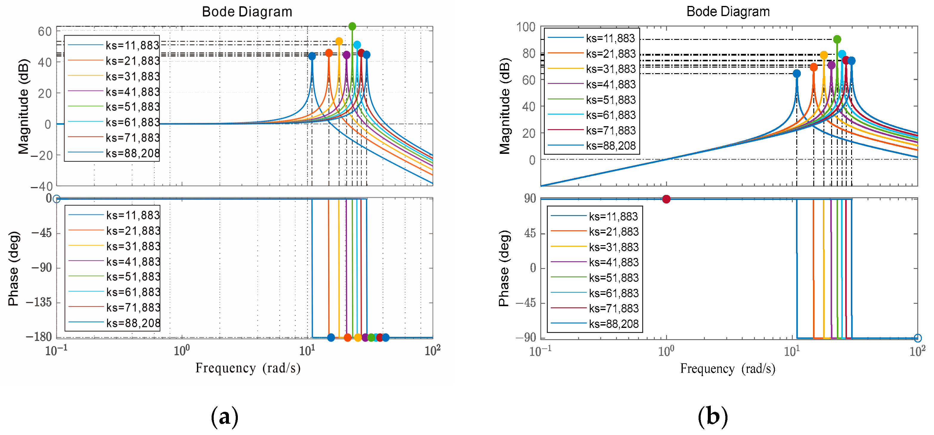
= 13,733 N/m, thus indicating a stiffness range of [11,883~88,208 N/m]. With intervals of 10,000, we selected ks values of 11,883 N/m, 21,883 N/m, 31,883 N/m, 41,883 N/m, 51,883 N/m, 61,883 N/m, 71,883 N/m, and 88,208 N/m, with cs = 0 and M = 100 kg. Using MATLAB/Simulink R2018a software, we analyzed the transfer functions of human displacement and acceleration to obtain Bode plots, as shown in Figure 7.
From Figure 7, it can be observed that the eight curves with different stiffness coefficients exhibit similar trends. At low frequencies, stiffness has minimal impact on the overall system, showing good magnitude and phase tracking characteristics, indicating system stability. A higher stiffness coefficient results in smaller displacement and acceleration of the human body. However, at higher frequencies, increasing the stiffness coefficient deteriorates the system stability, leading to larger displacement and acceleration of the human body. Therefore, to enhance the flexibility of human motion, the stiffness coefficient of the system cannot remain constant and needs to vary with the system frequency.
Similarly, based on the obtained equivalent mathematical model, the variation of the damping coefficient c1 of the MRD-1 plays a decisive role in the entire system, and the system’s damping range corresponds to the variation of c1. Combining the selected MRD-1, whose damping force F varies from 80 to 800 N, and considering a human motion velocity v = 1 m/s as an example, according to the damping coefficient calculation formula:
F = c s v
where cs is the damping coefficient of the damper, and v is the velocity of the human body.
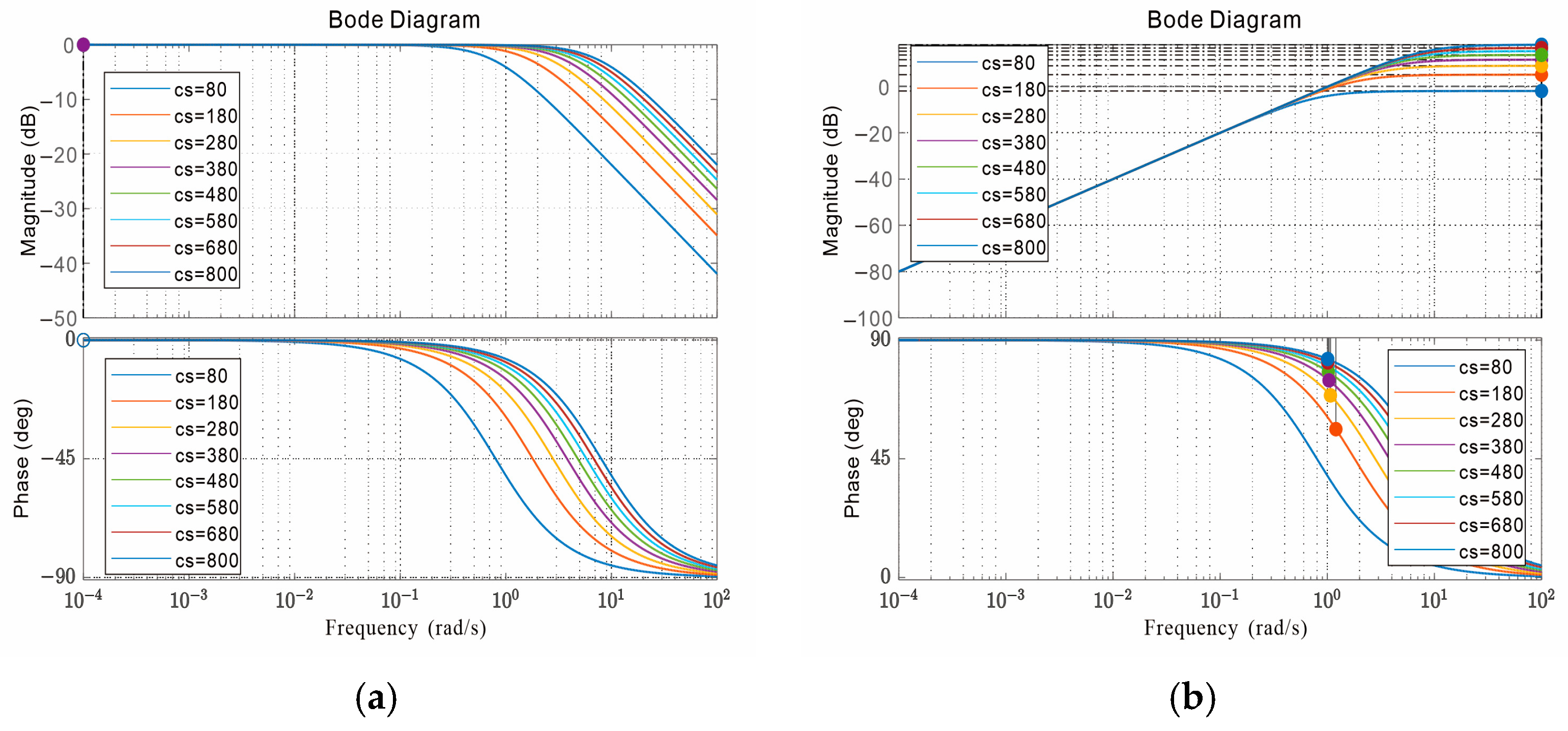
Finally, the system’s damping range was determined to be [80~800 Ns/m]. We selected cs values of 80 Ns/m, 180 Ns/m, 280 Ns/m, 380 Ns/m, 480 Ns/m, 580 Ns/m, 680 Ns/m, and 800 Ns/m, with ks = 0 and M = 100 kg. Using MATLAB/Simulink R2018a software, we analyzed the transfer functions of human displacement and acceleration to obtain Bode plots, as shown in Figure 8.
From Figure 8, it can be observed that the eight curves of different damping coefficients exhibit similar trends. At low frequencies, damping has little effect on the entire system, demonstrating good amplitude and phase characteristics. At high frequencies, as the damping coefficient increases, the system’s stability in terms of human displacement improves. Therefore, from the perspective of suppressing human displacement, it is advisable to increase the damping coefficient as much as possible. However, at high frequencies, with the increase in damping coefficient, human acceleration also increases. In such cases, it is necessary to reduce the damping coefficient.
The analysis above reveals that both stiffness and damping coefficients significantly impact human motion performance. Moreover, the required stiffness and damping coefficients vary at different frequencies. Therefore, a variable stiffness and damping structure are needed to achieve smooth motion. Both variable stiffness and variable damping are achieved through MRDs. Next, an analysis of the damping characteristics of MRDs is required.

3.4. The Damping Characteristics of MRDs

The MRD is a device that utilizes the rheological properties of magnetorheological fluid to adjust damping force. Its damping characteristics depend on the intensity of the magnetic field and the properties of the magnetorheological fluid, as well as the relationship between velocity and displacement [
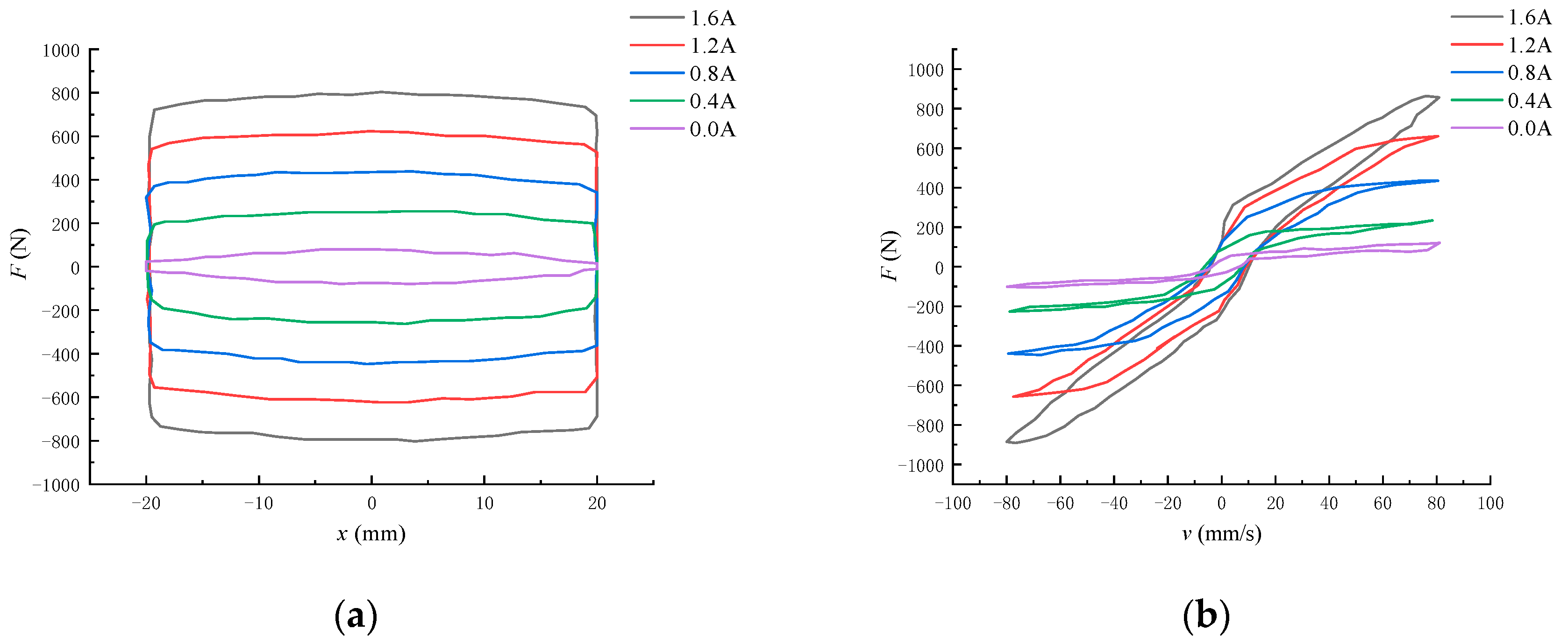
29]. The output damping mainly responds instantaneously to velocity, while displacement is the result of the long-term effect of velocity. Using a sinusoidal excitation input with an amplitude of 20 mm, frequency of 2 Hz, and velocity of 80 mm/s as an example, the Fx and Fv relationship curves of MRD-1 are shown in 
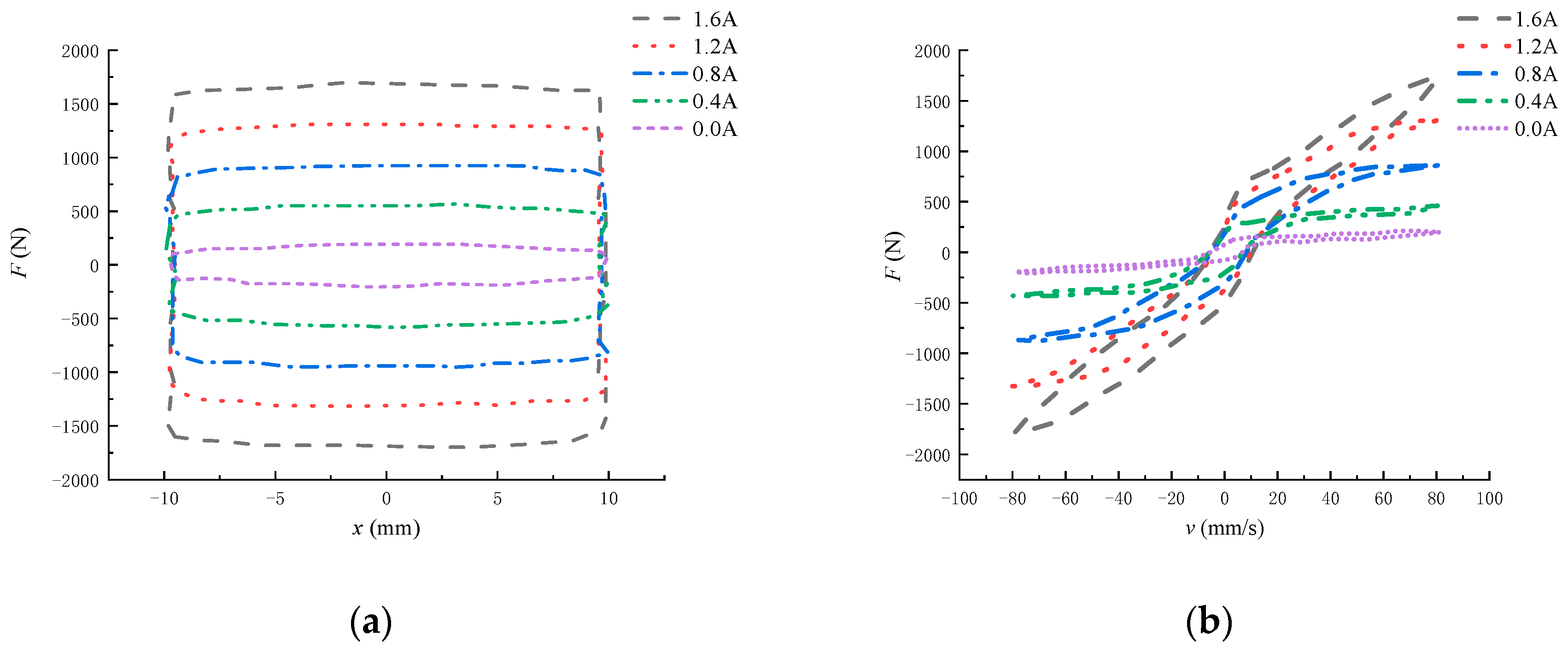
Figure 9 for input currents of 0.0, 0.4, 0.8, 1.2, and 1.6 A. Additionally, using a sinusoidal excitation input with an amplitude of 10 mm, frequency of 2 Hz, and velocity of 80 mm/s as an example, the Fx and Fv relationship curves of MRD-2 are shown in Figure 10 for input currents of 0.0, 0.4, 0.8, 1.2, and 1.6 A.
From Figure 9a and Figure 10a, it can be observed that the Fx curve of the dampers exhibits nonlinear characteristics. When the displacement is constant, the damping force increases with the increase in input current. When the input current is constant, the damping force is greater at a displacement close to 0 mm compared to other displacements because the velocity is higher at this point, resulting in a larger damping force. Once the displacement reaches a certain value, the damping force approaches saturation and does not change significantly with further displacement changes.
From Figure 9b and Figure 10b, it can be observed that the Fv curve of the dampers also exhibits nonlinear characteristics, with significant hysteresis effects. As the current increases, the degree of hysteresis also increases. When the input current is constant, the damping force increases with the increase in velocity, and the damping force changes direction when the velocity changes direction, indicating that the damping force direction aligns with the velocity direction. When the input velocity is constant, the damping force increases with the increase in current. After the current reaches 1.6 A, the damping force approaches saturation and remains relatively stable without significant changes with further variations in the current.
During the process of assisting the wearer in completing a gait cycle, the lower limb exoskeleton rehabilitation robot experiences a certain impact force when the foot makes contact with the ground. This impact force is transmitted through the foot sole, ankle joint, knee joint, and hip joint to the main body of the robot and the wearer. Therefore, a buffer is needed to dissipate this impact force. Instead of the traditional rigid connecting components of the robot, the buffer replaces the biological human calf. During the process from foot contact to lift-off, the calf undergoes compression and recovery phases. During the compression phase, both the damper and the spring are compressed simultaneously. At this time, a portion of the impact force is absorbed by the damper, while the rest is stored as elastic potential energy by the spring. During the recovery phase, the spring plays the main role in releasing the elastic potential energy stored during the compression phase, allowing the calf to quickly return to its initial state to perform the next gait action. Therefore, both the damper and the spring play crucial roles throughout the entire process. If the damping force of the damper is too large, the compression stroke of the buffer will be small, resulting in rapid energy dissipation but slow recovery of the buffer, sometimes not even fully recovered before the next action begins. If the damping force of the damper is too small, the buffer’s compression stroke will be large. During the compression phase, the energy that the damper cannot dissipate will be stored by the spring, leading to incomplete dissipation of the spring’s elastic potential energy during the recovery phase, resulting in a phenomenon known as secondary bounce of the robot.
The MRD can adjust the viscosity of the magnetorheological fluid by controlling the intensity of the magnetic field through the magnitude of the current, thereby controlling the damping characteristics of the damper. In addition to this, an optimal control strategy is required to ensure that the buffer dissipates the impact energy completely throughout the entire buffering process, reduces the maximum acceleration load on the robot, and ensures that the robot’s foot does not experience secondary lift-off, achieving rapid recovery of the buffer and maintaining the stability of the robot’s motion.

4. The Control Strategy for the VSDA

4.1. Switching Damping Control

The Skyhook damping control strategy was first proposed by Karnopp et al. in 1974 as a means to reduce structural vibrations. This control strategy is based on an idealized model known as a “skyhook”, which works by controlling the motion of dampers connected to the structure to reduce vibration [30]. In Skyhook control, the dampers work by simulating an idealized mass connected to the top of the structure. This mass senses structural vibration and applies forces opposite to the direction of the vibration to reduce it. Compared to traditional damping control methods such as fixed damping and active damping, Skyhook control is typically simpler and more economical because it does not require real-time sensor feedback or active controllers. However, Skyhook control has certain limitations, especially in applications involving nonlinear or nonstationary systems. In our case, based on the variable characteristics of the dampers in the variable stiffness damping system, we designed a switching damping control algorithm inspired by the Skyhook control algorithm. This algorithm switches the parameters or configurations of the dampers between different states to control vibrations, thereby improving the stability of the structure and the safety of walking for lower limb exoskeleton rehabilitation robots.
Through the analysis of the working principle of the variable stiffness and damping device, the damping force generated by MRD-1 can be expressed as
f d 1 = c 1 o n ( x ˙ x 0 ˙ ) x ˙   ( x ˙ x 0 ˙ ) > 0   c 1 o f f ( x ˙ x 0 ˙ ) x ˙   ( x ˙ x 0 ˙ ) 0
In the equation, c 1 o n and c 1 o f f , respectively, represent the maximum damping coefficient and the minimum damping coefficient when MRD-1 is energized.
The damping force generated by MRD-2 can be expressed as
f d 2 = c 2 o n ( x ˙ x m ˙ ) x ˙   ( x ˙ x 0 ˙ ) > 0   c 2 o f f ( x ˙ x m ˙ ) x ˙   ( x ˙ x 0 ˙ ) 0
In the equation, c 2 o n and c 2 o f f , respectively, represent the maximum damping coefficient and the minimum damping coefficient when MRD-2 is energized.
According to the above formula, combining MRD-1 and MRD-2 into different switch states yields 9 control modes, as shown in Table 3.

4.1.1. Sine Excitation Simulation Analysis

According to the structural design and selection of the VSDA, the parameters of the system were selected and are shown in Table 4.
We established a simulation model in the MATLAB/Simulink environment. The control block diagram of the switch damping control is shown in Figure 11.
Selecting a sinusoidal input as the excitation:
x 0 = X 0 s i n ( ω t )
In the equation, X 0 = 0.01 m, the excitation frequency is 2 Hz, and the sampling time is 2 s. The simulation results for human body displacement are shown in Figure 12a, and the simulation results for human body acceleration are shown in Figure 12b.
Combining the above simulation results, we measure the variation and fluctuation of each control mode using the root mean square (RMS), calculated by the following formula:
R M S = 1 n i = 1 n x i 2
where xi represents each data point in the dataset and n is the total number of data points.
The RMS values of pedestrian displacement x and x ¨ under nine control modes with sinusoidal excitation are listed in Table 5.

4.1.2. Random Excitation Simulation Analysis

In theory, the surface of pedestrian pathways is not perfectly flat. The classification of road surfaces is typically based on factors such as road function, traffic flow, vehicle types, pavement materials, and design standards. Using white noise as the input for road surface, the time–frequency spectrum function is
G q ( f ) = ( 2 π ) 2 G q ( n 0 ) n 0 2 v ,
where n 0 is the reference spatial frequency, n 0 = 0.01 m−1; G q ( n 0 ) is the road spectrum value at the reference spatial frequency; v is the pedestrian walking speed.
A- and B-grade road surfaces are typically urban main or secondary roads where pedestrians usually do not walk. We selected a C-grade road surface for simulation [31]. For the C-grade road surface, G q ( n 0 ) = 256 × 10−6 m3. We took the pedestrian walking speed as v = 1 m/s, and the sampling time as 2 s. The simulation results for pedestrian displacement are shown in Figure 13a, and the simulation results for pedestrian acceleration are shown in Figure 13b.
The RMS values of pedestrian displacement x and x ¨ under nine control modes with random excitation are listed in Table 6.
Simulation comparisons between the nine control methods under sinusoidal and random excitations indicate that, relative to traditional passive damping systems, variable stiffness and damping control methods exhibit superior vibration reduction performance, effectively attenuating the displacement and acceleration generated during human walking processes.

4.2. Fuzzy Switch Damping Control

Traditional control system theory typically requires accurate mathematical models and precise input–output relationships. However, in many practical situations, the system model may be very complex or incomplete, and the input–output relationship may not be so clear. Fuzzy control theory, through techniques such as fuzzy sets, fuzzy logic, and fuzzy inference, allows system designers to use fuzzy rules and language to describe the behavior of the system, thus achieving control of complex systems. It has been widely applied in industrial control, automotive control, power systems, robotics, etc. It can handle complex situations such as nonlinear systems, large-scale systems, and real-time systems, and has strong robustness and adaptability [32]. Therefore, in this study, a fuzzy controller was designed, combining fuzzy control with switch damping control, further validating the rationality of the variable stiffness and damping structure.

4.2.1. Design of Fuzzy Controller

Based on the mathematical model and the 3D model of the variable stiffness and damping system constructed above, there are two magnetorheological dampers in the system. Therefore, we designed two fuzzy controllers. According to the damping force calculation Formulas (17) and (18) in the Skyhook damping control, the input variables of the fuzzy controller are the velocity x ˙   of the human body mass M and the relative velocity x ˙ x 0 ˙ between the human body velocity and the ground velocity. The output variables are the damping coefficients c1 and c2 of the dampers.
Two input variables are defined with five linguistic variables each: x ˙ = {Negative Large (NL), Negative Small (NS), Zero (ZO), Positive Small (PS), Positive Large (PL)} and x ˙ x 0 ˙ = {Negative Large (NL), Negative Small (NS), Zero (ZO), Positive Small (PS), Positive Large (PL)}. The membership functions used are Gaussian type (gaussmf). The output variables are c1 = {Small (S), Medium (M), Large (L)} and c2 = {Small (S), Medium (M), Large (L)}, with the membership functions being generalized Bell type (gbellmf).To accommodate two different excitation modes, sine excitation and random excitation, under sine excitation, the domain of the input variables x ˙ is [−0.5, 0.5] and x ˙ x 0 ˙ is [−1.6, 1.6], respectively, while under random excitation, the domain of the input variables x ˙ is [−0.06, 0.06] and x ˙ x 0 ˙ is [−0.6, 0.6], respectively. The output variable c1’s domain is [80, 800], and the output variable c2’s domain is [200, 1700] under both excitation modes. The membership degree function curves are shown in Figure 14.

4.2.2. Fuzzy Controller Control Rule

The fuzzy control rules are the most critical part of a fuzzy controller, determining its control precision and performance. From the switch damping control method, it can be inferred that when the direction of x ˙ is consistent with   x ˙ x 0 ˙ , the output damping force should be increased as much as possible. Conversely, when the direction of x ˙ is opposite to   x ˙ x 0 ˙ , the output damping force should be decreased as much as possible. Based on this, the fuzzy control rules can be obtained, as shown in Table 7.
The fuzzy inference method employed is the Mamdani method, and the defuzzification method used is the min–max centroid method.

4.2.3. Modeling and Simulation of Fuzzy Controllers

Based on the designed fuzzy controller and control rules, we established a system simulation model in MATLAB/Simulink simulation software. The control block diagram of the fuzzy control constructed is shown in Figure 15.
We integrated the constructed fuzzy controller with the previously developed switch damping control as described above, while keeping the system parameters and transfer function of the controlled model unchanged. We already validated that when Control Mode 9, i.e., variable stiffness and variable damping system, is adopted, the control effect on human displacement and acceleration is optimal; and when Control Mode 4, i.e., high stiffness and high damping system, is adopted, the control effect on human displacement and acceleration is the worst. Next, we will only compare the control effects under different excitation conditions for Control Mode 9, Control Mode 4, and the fuzzy switch damping control state; the simulation results are shown in Figure 16, and RMS comparison is shown in Table 8.
From the comparison results in Table 8, it can be observed that under sinusoidal excitation, when employing fuzzy switch damping control, human displacement is optimized by 72.47% compared to the high stiffness and high damping system, and by 16.95% compared to the switch damping system. Human acceleration is optimized by 52.09% compared to the high stiffness and high damping system, and by 25.2% compared to the switch damping system. Under random excitation, when using fuzzy switch damping control, human displacement is optimized by 59.09% compared to the high stiffness and high damping system, and by 21.74% compared to the switch damping system. Human acceleration is optimized by 78.74% compared to the high stiffness and high damping system, and by 31.66% compared to the switch damping system. Therefore, fuzzy switch damping control exhibits better control effectiveness in terms of human stability and compliance.

5. Discussion

This study demonstrated that, based on traditional fixed stiffness, fixed damping, or only variable stiffness, or only variable damping devices, the principles and ranges of variable stiffness and variable damping were theoretically derived with magnetorheological (MR) technology as the core. By controlling the damping of two MRD, simultaneous adjustment of stiffness and damping could be achieved, and this structure was simpler and more compact. In terms of control methods, the combination of fuzzy control and switch damping control was chosen to overcome the shortcomings of traditional switch control, enabling more effective control of human body acceleration and displacement.
Finally, it should be noted that in this study, the assumed body mass was 100 kg, and a certain margin was reserved for the load capacity of the dampers and springs. While this may meet the needs of most wearers, it cannot rule out the possibility of some wearers being unsuitable, which has limitations. If the body mass is changed, corresponding adjustments may need to be made to the system parameters. Additionally, the output force of the MRD and the mold spring is only theoretically analyzed and calculated, and in practice, it may be affected by uncertain factors such as materials, dimensions, and magnetic permeability, leading to certain errors in the output results. Furthermore, the formulation of fuzzy control rule tables is a complex process and does not have uniqueness, which may affect the universality of the research results. Therefore, future work will further improve the robot-assisted patient training evaluation system based on this study, providing a basis for optimizing system control parameters and rehabilitation training strategies.

6. Conclusions

This paper aimed to improve the flexibility and stability of lower limb exoskeleton rehabilitation robots. Addressing the high stiffness issue of traditional robotic leg joint, we designed a compact and flexible leg joint. We proposed a mathematical model of variable stiffness and damping composed of two controllable damping MRDs and two fixed-stiffness mold springs. The dynamic equilibrium equations of the model were established based on Newton’s laws of motion, and transfer functions were derived. Utilizing the mathematical model and principles of variable stiffness and damping dampers, we designed the overall structure of the lower limb exoskeleton rehabilitation robot and the 3D model of the VSDA.
Combining human body height and weight, we selected the MRDs and mold springs for the variable stiffness and damping dampers, obtaining the range of stiffness and damping variations for the system. We analyzed the effects of stiffness and damping coefficients on human motion performance. Finally, based on the traditional Skyhook control algorithm, we designed the switch damping control method and analyzed the displacement and acceleration of the human body under sinusoidal road excitation and random road excitation with different control strategies. Subsequently, we integrated fuzzy control into this framework. Through MATLAB/Simulink simulation analysis, we found that under fuzzy switch damping control, the displacement and acceleration of the human body can be significantly improved, demonstrating better flexibility and stability, and achieving optimal control performance.

Author Contributions

Conceptualization, C.Z. (Chenglong Zhao), Y.W. and Z.L.; methodology, C.Z. (Chenglong Zhao) and C.Z. (Chongsong Zheng); software, C.Z. (Chenglong Zhao), Z.L., C.Z. (Chongsong Zheng) and L.Z.; validation, C.Z. (Chenglong Zhao) and C.Z. (Chongsong Zheng); writing—original draft preparation, C.Z. (Chenglong Zhao); writing—review and editing, C.Z. (Chenglong Zhao); supervision, Z.L. and Y.W.; project administration, L.Z. All authors have read and agreed to the published version of the manuscript.

Funding

This research is supported by the 2024 Guangxi Universities Enhancement of Research Capability for Young and Middle-aged Teachers Project No. 2024KY0447, the Special Fund for Bagui Scholars of the Guangxi Zhuang Autonomous Region No. 2019A08, the Guangxi Higher Education Undergraduate Teaching Reform Project of 2023 No. 2023JGA249, the 2019 Research Initiation Program for Introducing High-level Talents to Beibu Gulf University No. 2019KYQD03.

Data Availability Statement

Data are contained within the article.

Acknowledgments

The authors would like to thank the anonymous reviewers for their valuable suggestions.

Conflicts of Interest

Author Chongsong Zheng was employed by the company CATARC (Tianjin) Automotive Engineering Research Institute Co., Ltd. The remaining authors declare that the research was conducted in the absence of any commercial or financial relationships that could be construed as a potential conflict of interest.

References

  1. Zhao, J.D. Research on Self-Tuning Fuzzy Control of Walking Error of Humanoid Robot. Ph.D. Thesis, Tsinghua University, Beijing, China, 2024. [Google Scholar]
  2. Zhong, P.; Yang, S.; Zhang, C.; Wang, X.; Zhang, D.; Liu, M. Optimization of impedance control parameters for lower extremity exoskeleton robot. Sci. Technol. Eng. 2023, 23, 7831–7837. [Google Scholar] [CrossRef]
  3. Chen, J.; Li, Y.; Zeng, J. Adaptive active interactive control for lower limb rehabilitation robots with uncertainties. J. Cent. South Univ. (Sci. Technol.) 2021, 52, 4325–4335. [Google Scholar] [CrossRef]
  4. Zhang, Y. Research on the Control Strategy of Assist Mode of Lower Limb Exoskeleton Rehabilitation Robot. Master’s Thesis, Hebei University of Technology, Tianjin, China, 2024. [Google Scholar]
  5. Riener, R.; Lunenburger, L.; Jezernik, S.; Anderschitz, M.; Colombo, G.; Dietz, V. Patient-cooperative strategies for robot-aided treadmill training: First experimental results. IEEE Trans. Neural Syst. Rehabil. Eng. 2005, 13, 380–394. [Google Scholar] [CrossRef] [PubMed]
  6. Yin, G.; Zhang, X.; Chen, J.; Ma, W. Adaptive control of trajectory tracking for lower limb rehabilitation robot with model uncertainty. J. Electron. Meas. Instrum. 2016, 30, 8. [Google Scholar] [CrossRef]
  7. Tu, Y.; Zhu, A.; Song, J.; Shen, Z.; Zhang, X.; Cao, G. Adaptive guide control of human-robot interaction force for lower limb exoskeleton rehabilitation robot. J. Xi’an Jiaotong Univ. 2019, 53, 8. [Google Scholar] [CrossRef]
  8. Zhang, Y.M.; Wu, Q.C.; Chen, B.; Wu, H.T.; Liu, H.R. Fuzzy neural network impedance control of a soft rehabilitation exoskeleton robot for lower limbs. Robotics 2020, 42, 9. [Google Scholar] [CrossRef]
  9. Wang, A.; Ge, Y.; Hu, N.; Dan, Y.; Yu, J.; Lu, J. Control design of a lower limb rehabilitation robot based on gait data. Control Eng. 2021, 11, 28. [Google Scholar] [CrossRef]
  10. Huo, X.; Xia, Y.; Liu, Y.; Jiang, L.; Liu, H. Design and Development of a Rotary Serial Elastic Actuator for Humanoid Arms. In Intelligent Robotics and Applications; Springer: Cham, Switzerland, 2014. [Google Scholar] [CrossRef]
  11. Yu, H.; Huang, S.; Chen, G.; Thakor, N. Control design of a novel compliant actuator for rehabilitation robots. Mechatronics 2013, 23, 1072–1083. [Google Scholar] [CrossRef]
  12. Van Ham, R.; Vanderborght, B.; Van Damme, M.; Verrelst, B.; Lefeber, D. MACCEPA, the mechanically adjustable compliance and controllable equilibrium position actuator: Design and implementation in a biped robot. Robot. Auton. Syst. 2007, 55, 761–768. [Google Scholar] [CrossRef]
  13. Huang, T.H.; Kuan, J.Y.; Huang, H.P. Design of a new variable stiffness actuator and application for assistive exercise control. In Proceedings of the IEEE/RSJ International Conference on Intelligent Robots and Systems, San Francisco, CA, USA, 25–30 September 2011; pp. 372–377. [Google Scholar]
  14. Yang, K.; Huang, H. Improvement of magnetorheological fluid settling of MR damper for automobile suspensio. J. Shenyang Univ. Technol. 2022, 1, 41. [Google Scholar] [CrossRef]
  15. Liu, Z.-E.; An, H.-J.; Song, W.-Z.; Li, Y.-C. Research on automobile rollover prevention based on new magnetorheological damper. Automot. Technol. 2022. [Google Scholar] [CrossRef]
  16. Liu, X.; Yang, S.; Shen, Y.; Du, M. Research on automobile suspension control based on magnetorheological dampers. Vib. Shock. 2007, 26, 3. [Google Scholar] [CrossRef]
  17. Yuan, X. Fuzzy control of seismic response of building structures based on magnetorheological dampers. Low Temp. Build. Technol. 2022, 3, 44. [Google Scholar] [CrossRef]
  18. Wang, Z.; Wan, T.; Huo, X. Study on the control of longitudinal displacement of large-span suspension bridges under moving train load. Bridge Constr. 2023, 53, 104–111. [Google Scholar] [CrossRef]
  19. Cui, G.; Feng, Y.; Zou, J. Magnetorheological fluid vibration control damper in flexible robot. Mod. Manuf. Technol. Equip. 2016, 5, 59–60. [Google Scholar] [CrossRef]
  20. Li, F.; Xie, H.; Xu, X. Gait planning and control realization of heterogeneous two-legged robot. J. Northeast Univ. (Nat. Sci. Ed.) 2007, 28, 1081–1084. [Google Scholar] [CrossRef]
  21. Wang, B.; Jin, Y.; Xu, H.; Xu, X. Computational moment plus proportional differential feedback control of a robot bionic knee joint. J. Mech. Eng. 2008, 44, 179–183. [Google Scholar] [CrossRef]
  22. Pandit, S.; Godiyal, A.K.; Vimal, A.K.; Singh, U.; Joshi, D.; Kalyanasundaram, D. An Affordable Insole-Sensor-Based Trans-Femoral Prosthesis for Normal Gait. Sensors 2018, 18, 706. [Google Scholar] [CrossRef]
  23. Li, Z.D. Research on the intelligent control method of structural humanoid based on magnetorheological damper. Earthq. Eng. Eng. Vib. 2022, 42, 253–261. [Google Scholar] [CrossRef]
  24. Yang, K.; Huang, H. Mixed-mode magnetorheological damper for mechanical leg damping control. J. Fuzhou Univ. (Nat. Sci. Ed.) 2022, 50, 376–384. [Google Scholar] [CrossRef]
  25. Lanh, L.A.K.; Duong, V.T.; Nguyen, H.H.; Kim, S.B.; Nguyen, T.T. Hybrid adaptive control for series elastic actuator of humanoid robot. Int. J. Intell. Unmanned Syst. 2023, 11, 359–377. [Google Scholar] [CrossRef]
  26. Zhao, C.; Liu, Z.; Zhu, L.; Wang, Y. Design and Research of Series Actuator Structure and Control System Based on Lower Limb Exoskeleton Rehabilitation Robot. Actuators 2024, 13, 20. [Google Scholar] [CrossRef]
  27. Yongheng, Z. Survey and Analysis of Related Body Dimensions towards Adult Male and Female—A Case Study of Jiangsu Province in 2015. J. Wenzhou Univ. (Soc. Sci.) 2016, 3, 84–89. [Google Scholar]
  28. DIN ISO 10243; Tools for Pressing-Compression Springs with Rectangular Section-Housing Dimensions and Colour Coding. International Organization for Standardization: Geneva Switzerland, 2010.
  29. Abdalaziz, M.; Sedaghati, R.; Vatandoost, H. Development of a new dynamic hysteresis model for magnetorheological dampers with annular-radial gaps considering fluid inertia and compressibility. J. Sound Vib. 2023, 561, 117826. [Google Scholar] [CrossRef]
  30. Jinqiu, Z.; Dashan, H.; Yile, L. An Improved Skyhook Semi-active Control Algorithm. Comput. Meas. Control. 2015, 23, 2806–2808. [Google Scholar]
  31. Gou, Z.; Sun, Y.; Li, H. Simulation analysis of automobile driving smoothness under class B and class C pavement. Mech. Eng. 2014, 12, 129–131. [Google Scholar] [CrossRef]
  32. Li, L.-Y. Research on the application of fuzzy control algorithm in the control system of down filling machine. Electron. Qual. 2018, 1, 5–8, 14. [Google Scholar]
Figure 1. 3D model of lower limb exoskeleton rehabilitation robot.
Actuators 13 00132 g001
Figure 2. Pressure sensor and marker point distribution diagram: (a) Distributed flexible thin-film plantar pressure sensor; (b) placement of marker points.
Actuators 13 00132 g002
Figure 3. Vertical ground reaction force (GRF) curve.
Actuators 13 00132 g003
Figure 4. Mathematical model of VSDA: (a) Simplified model; (b) equivalent model.
Actuators 13 00132 g004
Figure 5. The overall structure of the lower limb exoskeleton rehabilitation robot. 1—control module, 2—waist adjustment mechanism, 3—hip joint SEDA (Series Elastic Damper Actuator), 4—ankle joint, 5—foot sole, 6—calf model, 7—variable stiffness and damping calf, 8—knee joint crank, 9—thigh model, 10—knee joint SEDA (Series Elastic Damper Actuator), 11—hip joint crank.
Actuators 13 00132 g005
Figure 6. Structure of the VSDA. (a) Cross-sectional view: 1—upper connector, 2—spring 1, 3—upper seal ring, 4—electromagnetic coil of MRD-1, 5—lower seal ring, 6—spring 2, 7—lower connector, 8—lower length adjustment hole, 9—energy storage spring, 10—electromagnetic coil of MRD-2, 11—magnetorheological fluid, 12—piston rod, 13—upper length adjustment hole; (b) three-dimensional model.
Actuators 13 00132 g006
Figure 7. Impact of stiffness coefficient on human motion performance: (a) Bode plot of human displacement; (b) Bode plot of human acceleration.
Actuators 13 00132 g007
Figure 8. Impact of damping coefficient on human motion performance: (a) Bode plot of human displacement; (b) Bode plot of human acceleration.
Actuators 13 00132 g008
Figure 9. MRD-1 damping characteristics: (a) Fx curve; (b) Fv curve.
Actuators 13 00132 g009
Figure 10. MRD-2 damping characteristics: (a) Fx curve; (b) Fv curve.
Actuators 13 00132 g010
Figure 11. The control block diagram of the switch damping control.
Actuators 13 00132 g011
Figure 12. Sinusoidal excitation under 9 control modes simulation results: (a) xt curve; (b) x ¨ t curve.
Actuators 13 00132 g012
Figure 13. Random excitation under 9 control modes simulation results: (a) xt curve; (b) x ¨ t curve.
Actuators 13 00132 g013
Figure 14. Membership degree functions: (a) Membership function of output variable c1; (b) membership function of output variable c2; (c) membership functions of input variables x ˙ under sinusoidal excitation; (d) membership functions of input variable x ˙ x 0 ˙ under sinusoidal excitation; (e) membership functions of input variables x ˙ under random excitation; (f) membership functions of input variables x ˙ x 0 ˙ under random excitation.
Actuators 13 00132 g014
Figure 15. Control block diagram of fuzzy control.
Actuators 13 00132 g015
Figure 16. The simulation results comparison: (a) sinusoidal excitation xt curve; (b) sinusoidal excitation x ¨ t curve; (c) random excitation xt curve; (d) random excitation x ¨ t curve.
Actuators 13 00132 g016aActuators 13 00132 g016b
Table 1. MRD parameters.
TitleStroke (mm)Total Length (mm)Outer Diameter of the Cylinder (mm)Damping Force (N)Current
MRD-1221702480~8000–1.6
MRD-2148050200~17000–1.6
Table 2. Spring parameters.
TitleStiffness (N/m)Maximum Load (N)Compression RateOuter Diameter (mm)Inner Diameter (mm)Length (mm)
Spring 188,208211740%502560
Spring 213,73320650%502530
Table 3. Switching damping control modes.
Control TypeMRD-1MRD-2Meaning
1OffOffBoth MRD-1 and MRD-2 are in the off state, resulting in a low damping, low stiffness system.
2OffOnDamping force of MRD-1 is small, damping force of MRD-2 is large, resulting in a low damping, high stiffness system.
3OnOffDamping force of MRD-1 is large, damping force of MRD-2 is small, resulting in a high damping, low stiffness system.
4OnOnBoth MRD-1 and MRD-2 are in the on state, resulting in a high damping, high stiffness system.
5On–offOffDamping force of MRD-1 is adjusted according to Formula (17), while the damping force of MRD-2 is relatively small.
6On–offOnDamping force of MRD-1 is adjusted according to Formula (17), while the damping force of MRD-2 is relatively large.
7OffOn–offDamping force of MRD-1 is relatively small, while the damping force of MRD-2 is adjusted according to Formula (18).
8OnOn–offDamping force of MRD-1 is relatively large, while the damping force of MRD-2 is adjusted according to Formula (18).
9On–offOn–offDamping force of MRD-1 is adjusted according to Formula (17), while the damping force of MRD-2 is adjusted according to Formula (18).
Table 4. System parameter table.
System ParameterNumerical ValueSystem ParameterNumerical Value
c1on (Ns/m)800k1 (N/m)88,208
c1off (Ns/m)80k2 (N/m)13,733
c2on (Ns/m)1700M (Kg)100
c2off (Ns/m)200
Table 5. The RMS values of human body x and x ¨ under sinusoidal excitation.
Control TypeMRD-1MRD-2 x /m x ¨ /mm−1
1OffOff0.00821.3144
2OffOn0.00951.5043
3OnOff0.00941.4562
4OnOn0.01781.6156
5On–offOff0.00831.3082
6On–offOn0.00791.2635
7OffOn–off0.00781.2616
8OnOn–off0.00731.1700
9On–offOn–off0.00591.0349
Table 6. The RMS values of human body x and x ¨ under random excitation.
Control TypeMRD-1MRD-2 x /m x ¨ /mm−1
1OffOff0.00370.0979
2OffOn0.00380.0670
3OnOff0.00380.1322
4OnOn0.00440.1472
5On–offOff0.00250.0946
6On–offOn0.00320.1133
7OffOn–off0.00370.0468
8OnOn–off0.00350.1377
9On–offOn–off0.00230.0458
Table 7. Fuzzy control rule table.
x ˙ x ˙ x 0 ˙
NLNSZOPSPL
NLLLSML
NSLMSSM
ZOSSSSS
PSMSSML
PLLMSLL
Table 8. The RMS values of human x and x ¨ under different excitation modes.
Control TypeMRD-1MRD-2Sinusoidal Excitation Random   Excitation
x /m x ¨ /mm−1 x /m x ¨ /mm−1
4OnOn0.01781.61560.00440.1472
9On–offOn–off0.00591.03490.00230.0458
Fuzzy Switch Damping ControlOn–offOn–off0.00490.77410.00180.0313
Disclaimer/Publisher’s Note: The statements, opinions and data contained in all publications are solely those of the individual author(s) and contributor(s) and not of MDPI and/or the editor(s). MDPI and/or the editor(s) disclaim responsibility for any injury to people or property resulting from any ideas, methods, instructions or products referred to in the content.

