
A Wear Prediction Framework for Ball-Screw of Electro-Mechanical Brake Unit on Railway Trains

Abstract
:1. Introduction
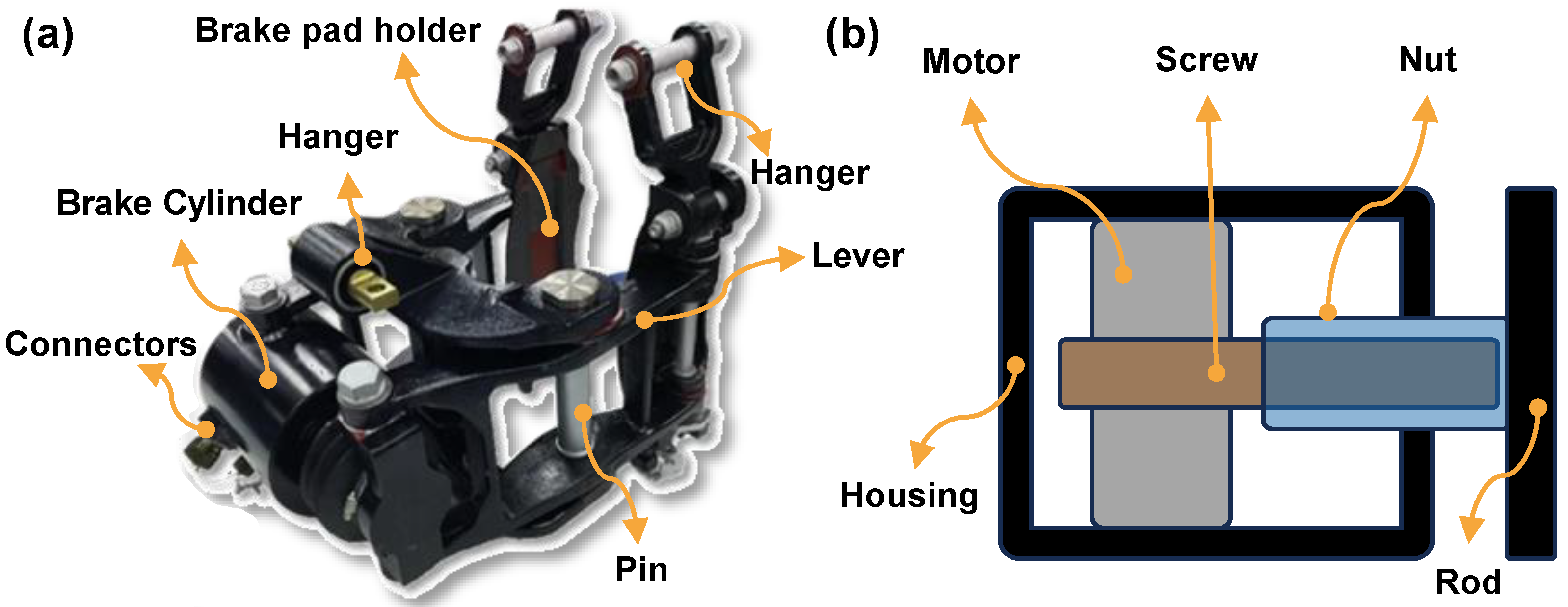
2. Working Principle of EMBUs
3. Wear Modeling
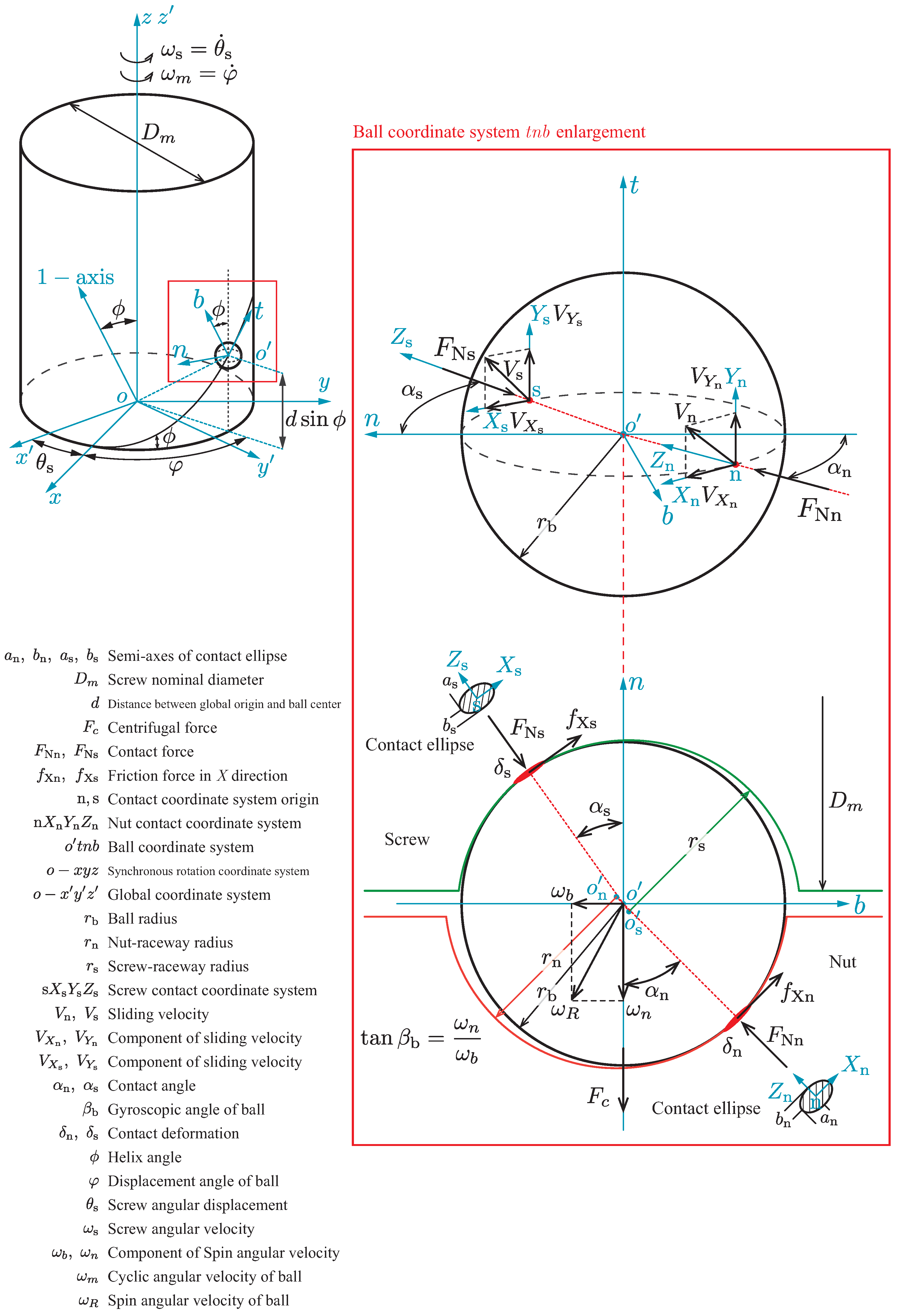
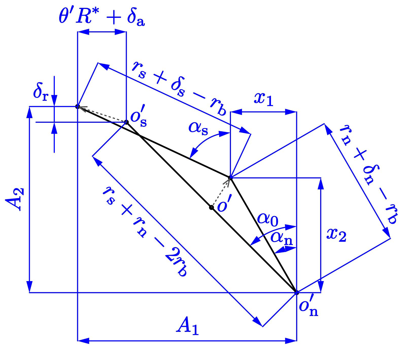
3.1. Contact Model
3.2. Dynamic Model
3.3. Wear Prediction Model
4. Wear Calculation and Test Validation
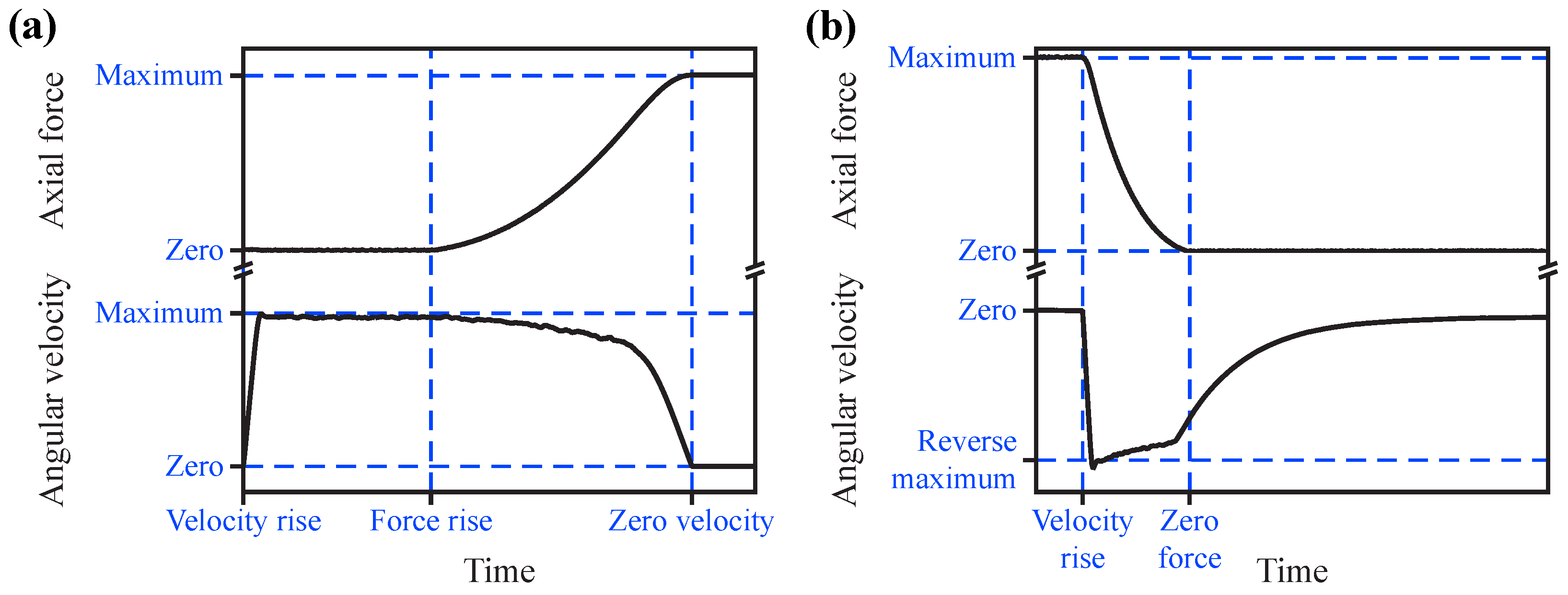
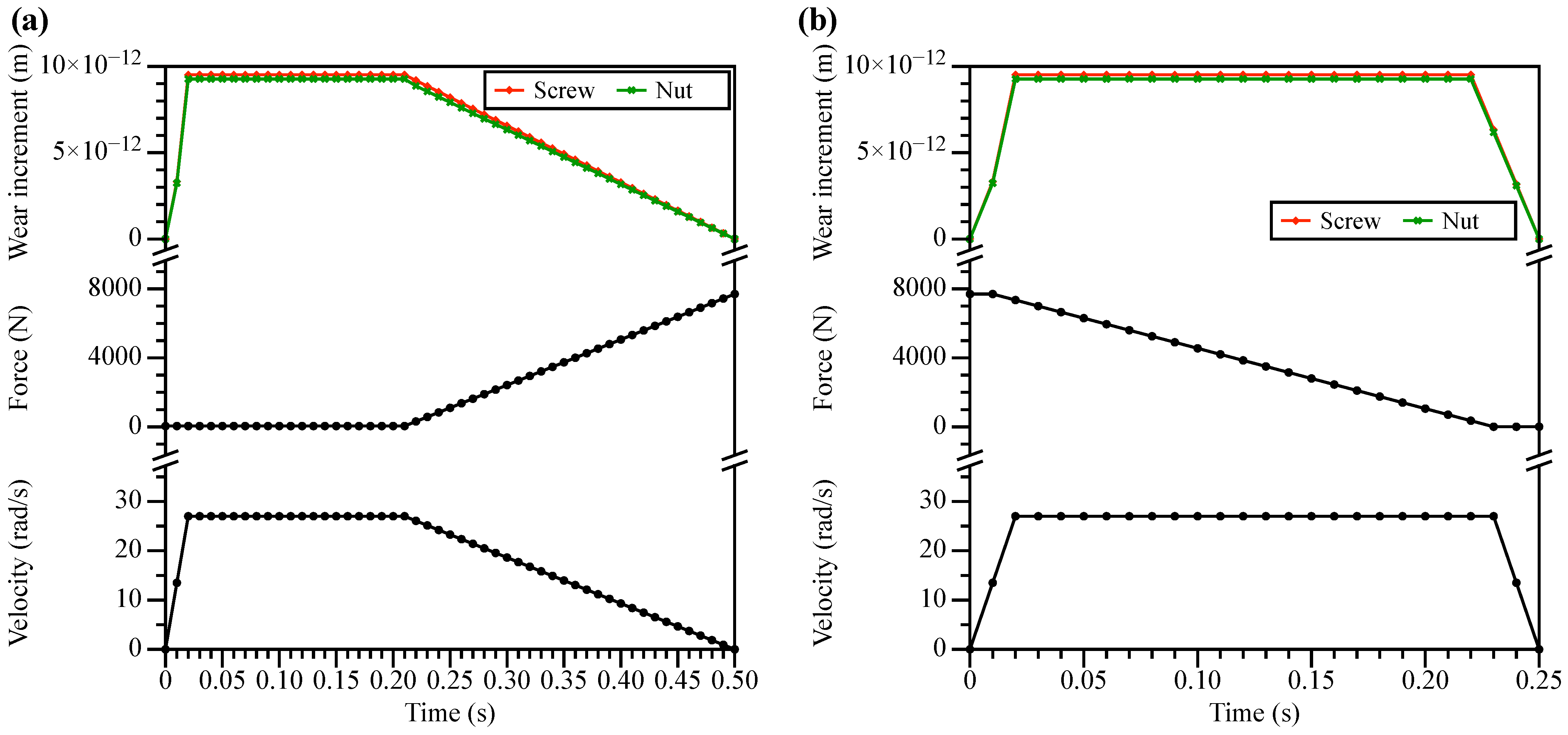
4.1. Working Condition Discretization
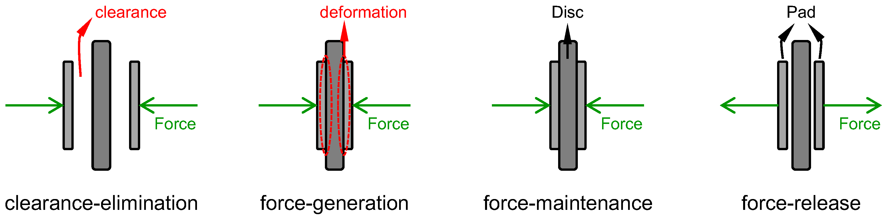
- Clearance–elimination: the angular velocity of the screw rises from zero to the maximum velocity and stays at that velocity for a period of time. The axial force moves the nut and the clamp lever to eliminate the clearance between the brake disc and pads.
- Force–generation: the angular velocity of the screw decreases from the maximum velocity while the axial force increases. Finally, the axial force reaches its maximum value and the screw angular velocity decreases to zero.
- Force–release phase: the angular velocity of the screw is reversed from zero to a maximum velocity and is maintained for a specific period of time. The reverse rotation of the screw drives the nut and clamp lever back, reducing the axial force. Then, when the target current reaches zero, the screw angular velocity decreases and the axial force also continues to decrease. Finally, the screw angular velocity reduces to zero and the axial force also decreases to zero.

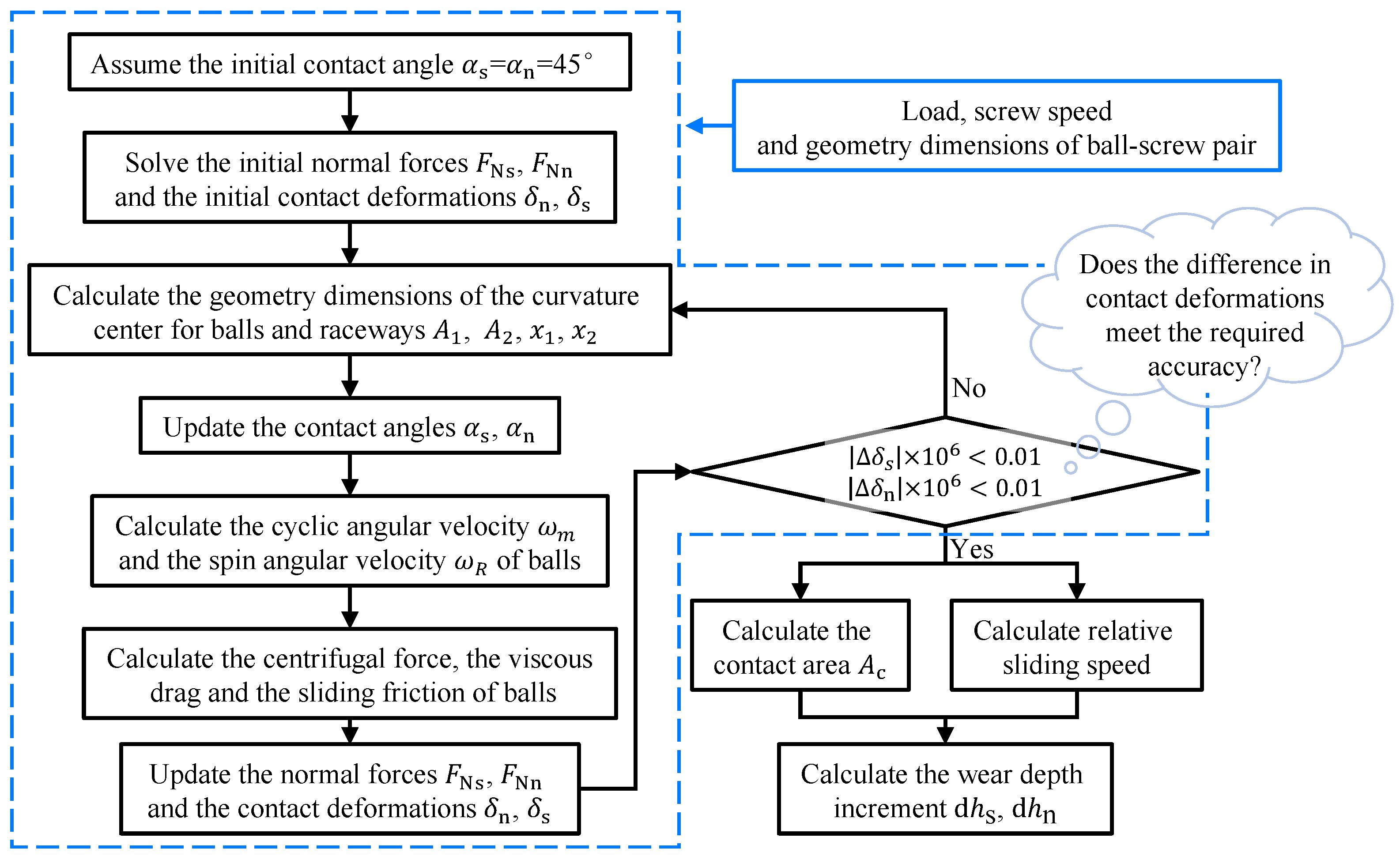
4.2. Numerical Calculation
- Repeat Steps 2 to 4 until the difference in contact deformations meets the required accuracy.
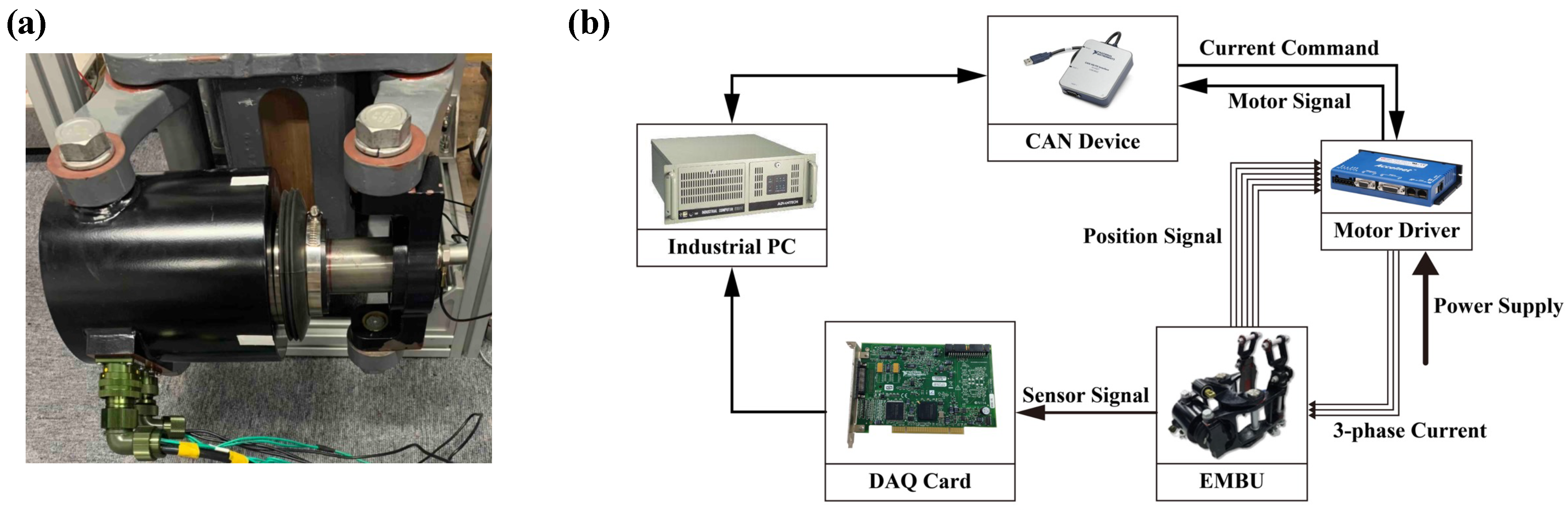
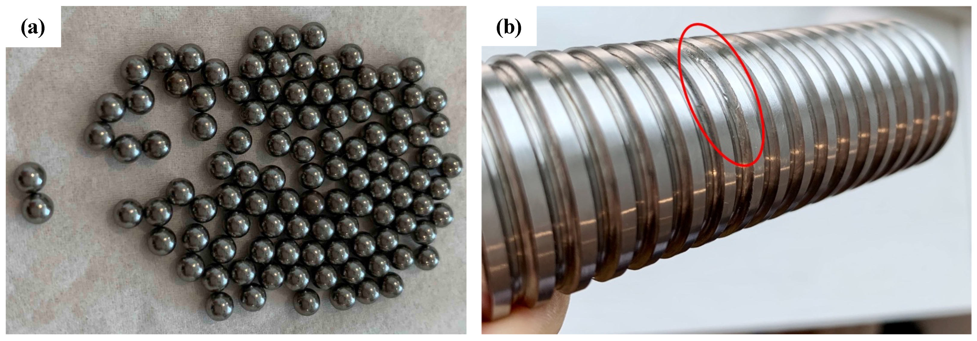
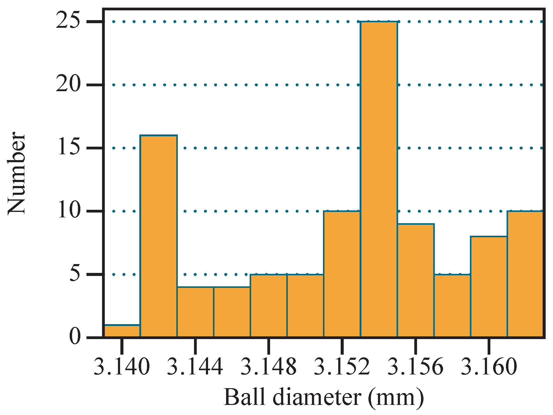
4.3. Test Validation
5. Results and Discussion
6. Conclusions
- The load is dynamically varied during the duty cycle of the EMBU, which has an effect on the contact type and wear increment of the ball and raceway. In this paper, the load is discretized to determine the elastic–plastic contact type to calculate the wear increment.
- The calculation results and the endurance test show that the wear of the screw-raceway is greater than that of the nut-raceway and that the effect of velocity is greater than the effect of axial force.
- The test results show that the presented calculation framework in this paper is reasonable. It can be used for ball-screw wear and internal clearance prediction.
Author Contributions
Funding
Data Availability Statement
Acknowledgments
Conflicts of Interest
Nomenclature
| r | radius |
| nominal diameter | |
| contact angle between balls and raceways | |
| helix angle | |
| principle curvature | |
| principle curvature of screw-raceway (direction of sliding velocity) | |
| principle curvature of screw-raceway (orthogonal direction) | |
| principle curvature of nut-raceway (direction of sliding velocity) | |
| principle curvature of nut-raceway (orthogonal direction) | |
| effective curvature ratio of the contact between ball and screw-raceway | |
| effective curvature ratio of the contact between ball and nut-raceway | |
| complete ellipticity integrals of the first kind | |
| complete ellipticity integrals of the second kind | |
| effective modulus | |
| ratio of the long and short semi-axes of the contact ellipse | |
| normal force at the ball–raceway contact | |
| axial force | |
| Z | effective number of balls |
| i | number of loaded turns |
| number of unloaded balls | |
| H | hardness |
| Poisson ratio of the softer object | |
| average effective curvature radius of asperities | |
| rotational angular velocity of the screw | |
| gyroscopic angle | |
| spin angular velocity | |
| mass of the ball | |
| initial dynamic viscosity | |
| ratio of equivalent radii | |
| pressure–viscosity parameter | |
| load of the contact | |
| boundary friction coefficient | |
| load shared by asperities | |
| relative axial angular between the screw and nut after loading | |
| relative axial displacement between the screw and nut after loading | |
| relative radial displacement between the screw and nut after loading | |
| component of the spin angular velocity in t-axis | |
| increment of wear volume | |
| increment of sliding distance | |
| pressure yield limit for the softer material | |
| dimensionless wear constant | |
| discrete time step | |
| increment of wear depth | |
| relative sliding velocity | |
| Subscripts | |
| b | ball |
| s | screw |
| n | nut |
| s or n |
References
- Wu, M.; Ma, T.; Tian, C.; Yang, J.; Chen, M. Discussion on development trend of train braking technology. China Railw. Sci. 2019, 40, 134–144. [Google Scholar] [CrossRef]
- Zhao, Y.; Lin, H.; Miao, F. An adaptive backstepping nonsingular fast terminal sliding-mode control for the electromechanical brake system with backlash nonlinearity compensation. Proc. Inst. Mech. Eng. Part F J. Rail. Rapid. Transit. 2023, 237, 858–870. [Google Scholar] [CrossRef]
- Baek, S.K.; Oh, H.K.; Kim, S.W.; Seo, S.I. A clamping force performance evaluation of the electro mechanical brake using PMSM. Energies 2018, 11, 2876. [Google Scholar] [CrossRef]
- Baek, S.K.; Oh, H.K.; Park, J.H.; Shin, Y.J.; Kim, S.W. Evaluation of efficient operation for electromechanical brake using maximum torque per ampere control. Energies 2019, 12, 1869. [Google Scholar] [CrossRef]
- Sun, X.; Yang, Z.; Yang, J. Typical failure mode and effect analysis of flight control electromechanical actuation system. In Proceedings of the CSAA/IET International Conference on Aircraft Utility Systems (AUS 2018), Guiyang, China, 19–22 June 2018; IET: London, UK, 2018; pp. 1162–1169. [Google Scholar]
- Li, C.; Zhuo, G.; Tang, C.; Xiong, L.; Tian, W.; Qiao, L.; Cheng, Y.; Duan, Y. A Review of Electro-Mechanical Brake (EMB) System: Structure, Control and Application. Sustainability 2023, 15, 4514. [Google Scholar] [CrossRef]
- Qiao, G.; Liu, G.; Shi, Z.; Wang, Y.; Ma, S.; Lim, T.C. A review of electromechanical actuators for More/All Electric aircraft systems. Proc. Inst. Mech. Eng. Part C J. Mech. Eng. Sci. 2018, 232, 4128–4151. [Google Scholar] [CrossRef]
- Meitinger, K.H. NEW CHASSIS SYSTEMS–Das fahrwerk des AUDI R8 e-tron (The chassis of the AUDI R8 e-tron). In Proceedings of the 7th International Munich Chassis Symposium 2016: Chassis. Tech Plus; Springer: Berlin/Heidelberg, Germany, 2017; pp. 89–102. [Google Scholar]
- Chen, Q.; Lv, Z.; Tong, H.; Zeng, D.; Ouyang, L.; Liu, Q. Study on multi-closed loop control of electro-mechanical braking for electric vehicles based on clamping force. Proc. Inst. Mech. Eng. Part D J. Automob. Eng. 2023. [Google Scholar] [CrossRef]
- Zhao, Y.; Lin, H.; Elahi, H.; Miao, F.; Riaz, S. Clamping force sensor fault analysis and fault-tolerant control of the electromechanical brake system. Arab. J. Sci. Eng. 2023, 48, 6011–6023. [Google Scholar] [CrossRef]
- Jones, A.B. A General Theory for Elastically Constrained Ball and Radial Roller Bearings Under Arbitrary Load and Speed Conditions. J. Basic Eng. 1960, 82, 309–320. [Google Scholar] [CrossRef]
- Harris, T. An analytical method to predict skidding in high speed roller bearings. Asle Trans. 1966, 9, 229–241. [Google Scholar] [CrossRef]
- Randall, R.B.; Antoni, J. Rolling element bearing diagnostics—A tutorial. Mech. Syst. Signal Process. 2011, 25, 485–520. [Google Scholar] [CrossRef]
- Wei, C.C.; Liou, W.L.; Lai, R.S. Wear analysis of the offset type preloaded ball–screw operating at high speed. Wear 2012, 292, 111–123. [Google Scholar] [CrossRef]
- Chang, W.; Etsion, I.; Bogy, D.B. An elastic-plastic model for the contact of rough surfaces. J. Tribol. 1987, 109, 257–263. [Google Scholar] [CrossRef]
- Cheng, Q.; Qi, B.; Liu, Z.; Zhang, C.; Xue, D. An accuracy degradation analysis of ball screw mechanism considering time-varying motion and loading working conditions. Mech. Mach. Theory 2019, 134, 1–23. [Google Scholar] [CrossRef]
- Zhao, J.; Lin, M.; Song, X.; Wei, N. A modeling method for predicting the precision loss of the preload double-nut ball screw induced by raceway wear based on fractal theory. Wear 2021, 486, 204065. [Google Scholar] [CrossRef]
- Zhao, J.; Lin, M.; Song, X.; Guo, Q. Analysis of the precision sustainability of the preload double-nut ball screw with consideration of the raceway wear. Proc. Inst. Mech. Eng. Part J J. Eng. Tribol. 2020, 234, 1530–1546. [Google Scholar] [CrossRef]
- Shen, J.W.; Feng, H.T.; Zhou, C.G.; Chen, Z.T.; Ou, Y. A new two-stage degradation model for the preload of ball screws considering geometric errors. Wear 2022, 500, 204352. [Google Scholar] [CrossRef]
- Zhang, Y.; Zhou, C.; Ren, S.; Qian, C.; Feng, H. An analysis method for the transmission efficiency of the preloaded ball screw based on wear volume calculation. Proc. Inst. Mech. Eng. Part J J. Eng. Tribol. 2022, 236, 2392–2405. [Google Scholar] [CrossRef]
- Cheng, Q.; Qi, B.; Liu, Z.; Yang, C.; Zheng, J. Positioning accuracy degradation and lifetime prediction of the ball screw considering time-varying working conditions and feed modes. Proc. Inst. Mech. Eng. Part B J. Eng. Manuf. 2021, 235, 943–957. [Google Scholar] [CrossRef]
- Zhang, H.; Zhang, J.; Liu, H.; Liang, T.; Zhao, W. Dynamic modeling and analysis of the high-speed ball screw feed system. Proc. Inst. Mech. Eng. Part B J. Eng. Manufac. 2015, 229, 870–877. [Google Scholar] [CrossRef]
- Okwudire, C.E.; Altintas, Y. Hybrid Modeling of Ball Screw Drives With Coupled Axial, Torsional, and Lateral Dynamics. J. Mech. Des. 2009, 131, 071002. [Google Scholar] [CrossRef]
- Xu, M.; Li, C.; Zhang, H.; Liu, Z.; Zhang, Y. A comprehensive nonlinear dynamic model for ball screw feed system with rolling joint characteristics. Nonlinear Dyn. 2021, 106, 169–210. [Google Scholar] [CrossRef]
- Jin, L.; Li, C.; Wang, X.; Xie, L. A dynamic stiffness model for high-speed ball screw pair with the mass center of screw nut considered. Mech. Ind. 2023, 24, 21. [Google Scholar] [CrossRef]
- Zhou, C.G.; Xie, J.L.; Feng, H.T. Investigation of the decompression condition of double-nut ball screws considering the influence of the geometry error and additional elastic unit. Mech. Mach. Theory 2021, 156, 104164. [Google Scholar] [CrossRef]
- Yin, Z.; Hu, N.; Chen, J.; Yang, Y.; Shen, G. A review of fault diagnosis, prognosis and health management for aircraft electromechanical actuators. IET Electr. Power App. 2022, 16, 1249–1272. [Google Scholar] [CrossRef]
- Bodden, D.S.; Clements, N.S.; Schley, B.; Jenney, G. Seeded failure testing and analysis of an electro-mechanical actuator. In Proceedings of the 2007 IEEE Aerospace Conference, Big Sky, MT, USA, 3–10 March 2007; IEEE: Piscataway, NJ, USA, 2007; pp. 1–8. [Google Scholar]
- Isturiz, A.; Vinals, J.; Abete, J.M.; Iturrospe, A. Health monitoring strategy for electromechanical actuator systems and components, screw backlash and fatigue estimation. In Proceedings of the Recent Advances in Aeropsace Actuation Systems and Components, Toulouse, France, 13–14 June 2012. [Google Scholar]
- Mansouri, B.; Piaton, J.; Guyamier, A. The backlash gap size estimation for electromechanical actuator in an operational behavior. In Proceedings of the Third European Conference of the Prognostics and Health Management Society 2016, Bilbao, Spain, 5–8 July 2016; PHM Society: Rochester, NY, USA, 2016; pp. 1–6. [Google Scholar]
- Fu, J.; Maré, J.C.; Yu, L.; Fu, Y. Multi-level virtual prototyping of electromechanical actuation system for more electric aircraft. Chin. J. Aeronaut. 2018, 31, 892–913. [Google Scholar] [CrossRef]
- Fu, J.; Maré, J.C.; Fu, Y. Modelling and simulation of flight control electromechanical actuators with special focus on model architecting, multidisciplinary effects and power flows. Chin. J. Aeronaut. 2017, 30, 47–65. [Google Scholar] [CrossRef]
- Hertz, H. Über die Berührung fester elastischer Körper (On the contact of elastic solids). J. Reine Angew. Math. 1882, 92, 156–171. [Google Scholar] [CrossRef]
- Markho, P. Highly accurate formulas for rapid calculation of the key geometrical parameters of elliptic Hertzian contacts. J. Tribol. 1987, 109, 640–647. [Google Scholar] [CrossRef]
- Tabor, D. The Hardness of Metals; Oxford University Press: Oxford, UK, 2000. [Google Scholar]
- Chang, W.R.; Etsion, I.; Bogy, D.B. Static Friction Coefficient Model for Metallic Rough Surfaces. J. Tribol. 1988, 110, 57–63. [Google Scholar] [CrossRef]
- Horng, J.H. An elliptic elastic-plastic asperity microcontact model for rough surfaces. J. Tribol. 1998, 120, 82–88. [Google Scholar] [CrossRef]
- Wei, C.C.; Lin, J.F. Kinematic analysis of the ball screw mechanism considering variable contact angles and elastic deformations. J. Mech. Des. 2003, 125, 717–733. [Google Scholar] [CrossRef]
- Houpert, L. Ball bearing and tapered roller bearing torque: Analytical, numerical and experimental results. Tribol. Trans. 2002, 45, 345–353. [Google Scholar] [CrossRef]
- Xu, X.; Tang, W.; Yu, T.; Yin, M. Wear prediction of ball screw using Archard model. Modul. Mach. Tool Autom. Manuf. Tech. 2016, 2016, 54–59. [Google Scholar] [CrossRef]
- Lin, M.; Ravani, B.; Velinsky, S. Kinematics of the ball screw mechanism. J. Mech. Design 1994, 116, 849–855. [Google Scholar] [CrossRef]
- Archard, J. Contact and rubbing of flat surfaces. J. Appl. Phys. 1953, 24, 981–988. [Google Scholar] [CrossRef]
- Xu, X.H.; Wang, Y.H.; Xu, D. Wear prediction of ball screw based on adhesive wear. In Proceedings of the 4th International Conference on Advanced Design and Manufacturing Engineering (ADME 2014), Hangzhou, China, 26–27 July 2014; Trans Tech Publications, Ltd.: Stafa-Zurich, Switzerland, 2014; pp. 261–265. [Google Scholar]
- Fein, R.S. Boundary lubrication. In Handbook of Lubrication Theory and Practice of Tribology; CRC Press: Boca Raton, FL, USA, 1984; Volume 2, pp. 49–68. [Google Scholar]
- Zhao, G.; Fan, Y.; Luo, X.; Li, L. Elastic-plastic contact deformation of precise ball screw pair in overload condition. J. Nanjing Univer. Sci. Tech. 2014, 38, 192–198. [Google Scholar]
- Palmgren, A. Ball and Roller Bearing Engineering; SKF Industries Inc.: Lansdale, PA, USA, 1959. [Google Scholar]


| Symbol Meaning | Symbol and Formula |
|---|---|
| Principle curvature of ball | |
| Principle curvature of screw-raceway (direction of sliding velocity) | |
| Principle curvature of screw-raceway (orthogonal direction) | |
| Principle curvature of nut-raceway (direction of sliding velocity) | |
| Principle curvature of nut-raceway (orthogonal direction) | |
| Sum of principle curvature at ball–screw contact | |
| Sum of principle curvature at ball–nut contact | |
| Effective curvature ratio of the contact between ball and screw-raceway | |
| Effective curvature ratio of the contact between ball and nut-raceway |
| Symbol | Value |
|---|---|
| 1.5875 mm | |
| 32 mm | |
| Z | 124 |
| 2.8473° | |
| 0.04 Pa·s | |
| 2.2 m2/N |
| Clearance–Elimination and Force–Generation Phase (m) | Force–Release Phase (m) | Sum (m) | |
|---|---|---|---|
| Screw-raceway | 8.4848 × 10⁻¹¹ | 6.3585 × 10⁻¹¹ | 1.4843 × 10⁻¹⁰ |
| Nut-raceway | 8.4848 × 10⁻¹¹ | 5.3024 × 10⁻¹¹ | 1.3787 × 10⁻¹⁰ |
Disclaimer/Publisher’s Note: The statements, opinions and data contained in all publications are solely those of the individual author(s) and contributor(s) and not of MDPI and/or the editor(s). MDPI and/or the editor(s) disclaim responsibility for any injury to people or property resulting from any ideas, methods, instructions or products referred to in the content. |
© 2024 by the authors. Licensee MDPI, Basel, Switzerland. This article is an open access article distributed under the terms and conditions of the Creative Commons Attribution (CC BY) license (https://creativecommons.org/licenses/by/4.0/).
Share and Cite
Ma, T.; Weng, J.; Tian, C.; Wu, M. A Wear Prediction Framework for Ball-Screw of Electro-Mechanical Brake Unit on Railway Trains. Actuators 2024, 13, 135. https://doi.org/10.3390/act13040135
Ma T, Weng J, Tian C, Wu M. A Wear Prediction Framework for Ball-Screw of Electro-Mechanical Brake Unit on Railway Trains. Actuators. 2024; 13(4):135. https://doi.org/10.3390/act13040135
Chicago/Turabian StyleMa, Tianhe, Jingjing Weng, Chun Tian, and Mengling Wu. 2024. "A Wear Prediction Framework for Ball-Screw of Electro-Mechanical Brake Unit on Railway Trains" Actuators 13, no. 4: 135. https://doi.org/10.3390/act13040135