Article

Adaptive Quick Sliding Mode Reaching Law and Disturbance Observer for Robust PMSM Control Systems

1
Department of Electrical and Computer Engineering, Sungkyunkwan University, Suwon 16419, Republic of Korea
2
Process Intelligence Research Team, HyundaiSteel Research Center, Seongnam 13494, Republic of Korea
3
Department of Smart Fab. Technology, Sungkyunkwan University, Suwon 16419, Republic of Korea
*
Author to whom correspondence should be addressed.
Actuators 2024, 13(4), 136; https://doi.org/10.3390/act13040136
Submission received: 7 March 2024 / Revised: 1 April 2024 / Accepted: 6 April 2024 / Published: 8 April 2024
(This article belongs to the Special Issue Actuators in 2024)

Abstract

:
The permanent magnet synchronous motor (PMSM) has been of interest to eco-friendly industries on account of its advantages such as high performance, efficiency, and precision control. However, perturbations due to PMSM parameter uncertainty, load torque, and external disturbance interfere with the construction of PMSM precision control systems. Therefore, a robust control system is needed to avoid unnecessary system movement caused by perturbations. In this paper, sliding mode control (SMC) is adopted to implement a robust control system for the PMSM. In order to reduce the reaching time from the initial system state to the sliding surface and the chattering phenomenon that can cause the system to malfunction, the adaptive quick sliding mode reaching law based on an exponential function and power equation is proposed. Although the SMC is robust to disturbance and parameter uncertainty, unexpected disturbances can destabilize the system. To estimate the unmatched disturbance in a short time, the second-order fast terminal sliding mode observer (SFTSMO) is proposed. The results show that the motor control system based on the proposed method has a fast convergence speed to an objective value, position tracking performance, and robustness.

1. Introduction

Recently, many countries and companies have begun to establish policies for eco-friendly industries to protect the environment and convert energy systems. The permanent magnet synchronous motor (PMSM) is an important motor and power device for generating electric fields. Since PMSM is advantageous in low- and mid-power applications and has high performance, various industries, i.e., electric vehicles, aerospace works, and robotics, have adopted PMSM-based systems [1,2,3]. The strengths of PMSM systems compared to other motor systems, such as brushless motor or direct current motor systems, include high air-gap flux density, high torque-to-inertia ratio, and high efficiency. However, the PMSM is associated with the nonlinear and time-varying parameters from unshaped dynamics, uncertainty, and internal or external perturbations. Therefore, the proportional-integral (PI) control method is limited regarding high performance since there are no mathematical components to counteract external and internal errors. In addition, the cascade control system is not able to satisfy or handle precisely the specific requirements of the motor, which contains nonlinear parameter variations and coupling [4,5].
To overcome the limited performance of PI control systems, many researchers have studied nonlinear control systems for PMSM speed regularization, e.g., predictive [6,7], neural network control [8,9], fuzzy control [10], stepping control [11], and sliding mode control (SMC) [12,13,14]. Among various nonlinear control methods, SMC, which has the advantages of robustness to external disturbance and low sensitivity about parameter uncertainty, is frequently used. Liu [15] proposed an SMC method based on a second-order nonsingular terminal sliding surface for the combined controller that can handle current and speed together. Leu [16] proposed a fuzzy-based sliding mode controller for PMSM control by combining the fuzzy control method and the SMC method. Using the fuzzy-based sliding mode controller, the system’s nonlinearity and unmolded uncertainty can be mitigated. Qian [17] designed a nonlinear sliding surface improved by the damping ratio of a variable system. Based on the nonlinear sliding surface, the PMSM control system mitigates the unmatched uncertainties and alleviates the system chattering caused by the signum function. Merabet [18] established a cascade second-order sliding mode control system. To improve the robustness of the system, the control system consists of inner and outer loops, which are the q-current controller and speed controller, respectively.
However, robustness is related to the switching gain that is represented by the signum function. To ensure the robustness of the SMC system, a large switching gain is required. The large switching gain can derive the time delay in the switching control law and high-frequency dynamics known as the chattering phenomenon. Therefore, an adaptive system that changes with time is required to improve the performance of the controller [19,20]. Many methods have been designed to suppress the chattering phenomenon such as the high-order sliding mode control [21], nonsingular sliding mode control [22], and fuzzy logic combined sliding mode control method [23]. Nevertheless, for the sliding mode controller with an improved sliding surface, the reaching speed to the sliding surface is increased by a functional sliding surface. Moreover, it is difficult to determine the upper and lower bounds of the disturbance caused by the signum function using a constant switching gain.
The main contributions of the proposed control system are as follows:
  • To reduce the strength of the trade-off between large constant switching gains and improve the reaching time, in this paper, a novel reaching law termed the adaptive quick reaching law (AQRL) is proposed. The AQRL is based on second-order sliding mode characteristics and switching function. In addition, the switching function is based on an exponential term and system state.
  • By utilizing a sliding mode disturbance observer (SMDO), we obtain robustness against a sudden disturbance and parameter uncertainty. SMDO methods have been studied to estimate disturbance and mismatched parameter uncertainty [24,25]. Moreover, to respond to disturbance more accurately and avoid the immoderate switching gain for SMDO, a high-order terminal sliding mode observer (HOTSMO) is also used in this paper.
  • The proposed AQRL is verified by the Lyapunov second method, and it is also mathematically demonstrated that this reaching time is faster than that of the conventional reaching law.
The rest of this paper is organized as follows: In Section 2, the AQRL is introduced, and the reduced reaching time and chattering are verified. In addition, the results of simulations using a second-order single-input single-output (SISO) system are presented to demonstrate the improved performance compared with the conventional sliding mode reaching law. Section 3 presents a PMSM mathematical model. To establish a robust PMSM speed controller, the sliding surface is designed and the AQRL is applied. Furthermore, SFTSMO is introduced to estimate the disturbance that can interrupt PMSM speed regulation. In Section 4, the simulation is presented to demonstrate the effectiveness of the proposed method for PMSM control. Finally, Section 5 concludes the study.

2. Adaptive Quick Reaching Law Design and Analysis

2.1. Adaptive Quick Reaching Law-Based Sliding Mode Control Design

SMC is a nonlinear control method with less sensitivity to parameter fluctuations and disturbances when the system trajectory reaches a sliding surface ( s ( t ) ) established by the error between the desired value and measured value. To design controller input for manipulating the controlled object, the switching term enables the state to be reached and maintained at the sliding surface. In order to achieve stability of the sliding mode controller, the Lyapunov function is used to process the controller input. The Lyapunov stability criterion [26] is expressed as follows:
V s = 1 2 s 2 , V ˙ ( s ) = s s ˙ 0 .
To satisfy the condition of the derivative of the Lyapunov function being less than or equal to zero, the conventional sliding mode reaching law denotes s ˙ = η sgn ( s ) , where the switching gain ( η ) is a positive constant. Equation (2) represents the reaching time ( t ) based on the conventional reaching law (CRL). From the initial state ( s ( 0 ) 0 ) to the sliding surface ( s ( t ) = 0 ) , the reaching time t, derived according to the conventional sliding mode reaching law, is as follows:
t = | s ( 0 ) | η .
Equation (2) indicates that the reaching time is influenced by the initial state and switching gain η . A large value of η reduces the reaching time for faster responses by the system. However, with a large η , the chattering phenomenon that adversely affects system performance occurs due to the sgn ( · ) . Therefore, a suitable value of η needs to be chosen to suppress chattering while maintaining a fast reaching time on the sliding surface [27,28]. In this paper, an AQRL is proposed to overcome the vulnerability of SMC.
s ˙ = g ( x 1 , s ) sgn ( s ) , g ( x 1 , s ) = k 1 ( e a | s | 1 ) + k 2 x 1 2 1 + | x 1 | e b | s | ,
where x 1 denotes the system state and the final value of x 1 ( ) is supposed to be 0. The parameters a , b , k 1 , and k 2 represent positive tuning parameters with the boundary conditions 0 < a < 1 , 0 < b < ln 2 , k 1 > 0 , and k 2 > 0 , respectively.
Assumption 1. 
The first interval is assumed as t 1 , which is from s ( 0 ) > 1 to s ( t ) = 1 , and the second interval is assumed as t 2 , which is from s ( t ) = 1 to s ( t ) = 0 .
To verify the stability of the proposed reaching law, which establishes a sliding surface with an exponential function, the constraint in Equation (1) is used.
s s ˙ = s k 1 ( e a | s | 1 ) sgn ( s ) k 2 x 1 2 1 + | x 1 | e b | s | sgn ( s ) = k 1 ( e a | s | 1 ) · | s | k 2 x 1 2 1 + | x 1 | e b | s | | s | < 0 .
In Equation (4), ( e a | s | 1 ) is a positive value regardless of s and a. Similarly, e b | s | also produces a positive value. Therefore, the proposed method satisfies the inequality for the Lyapunov stability criteria. The inequality shows that the system induced in Equation (3) achieves stabilization within a finite time.
The proposed switching gain g ( x 1 , s ) has been designed based on an exponential function and a nonlinear sliding surface. In addition, the initial sliding surface is affected by the switching gain g ( x 1 , s ) . The reaching process can be divided into two intervals when the initial condition s ( 0 ) is greater than one: the first interval means the time consumed to reach from the initial condition s ( 0 ) to s ( t ) = 1 , and the second interval is the time consumed to reach from s ( t ) = 1 to the sliding surface s ( t ) = 0 [29]. For the first interval, the term e a | s | 1 in Equation (3) becomes much larger than the second term e b | s | with the positive parameters k 1 and k 2 . In the first interval, the impact of the first term in Equation (3) is much greater, which means that the second term can be treated as trivial. Therefore, Equation (3) is transformed as follows:
s ˙ k 1 ( e a | s | 1 ) sgn ( s ) = k 1 ( e a · s 1 ) .
When the system is in the first interval, the reaching time is obtained by integrating Equation (5) as follows:
t 1 = s ( 0 ) 1 1 k 1 ( 1 e a s ) d s ,
where t 1 denotes the reaching time required in the first interval. From Equation (6), t 1 is
t 1 = 1 s ( 0 ) k 1 ln ( 1 e a ) ln ( 1 e a s ( 0 ) ) a k 1 .
In calculating the reaching time of the second interval, the second term in Equation (3) has a greater effect since the second term is larger than the first term. Therefore, the switching gain can be changed as
s ˙ k 2 x 1 2 1 + | x 1 | e b | s | sgn ( s ) = k 2 x 1 2 1 + | x 1 | e b s .
The process of calculating the time taken for the system state to move from s ( t ) = 1 to s ( t ) = 0 is the same as derived in Equations (6) and (7). The reaching time ( t 2 ) in the second interval is as follows:
t 2 = | x 1 | + 1 b k 2 x 1 2 e b 1 .
By combining Equations (7) and (9), the time ( t r 1 ) required for the system to reach the sliding surface in the initial system state is obtained. Since the value of e b 1 is between 0 and 1 according to 0 < b < ln 2 with optimally chosen k 1 and k 2 , t r 1 is represented by the inequality condition as
t r 1 = t 1 + t 2 < 1 s ( 0 ) k 1 ln ( 1 e a ) ln ( 1 e a s ( 0 ) ) a k 1 + | x 1 | + 1 b k 2 x 1 2 1 s ( 0 ) k 1 .
To prove the effectiveness of the proposed method, t r 1 is compared with t by subtracting Equation (2) from Equation (10),
t r 1 t < 1 s ( 0 ) k 1 s ( 0 ) η < 0 .
Therefore, with k 1 that satisfies the condition k 1 η , we can prove that the proposed reaching law attenuates the reaching time to the sliding surface in comparison with the conventional sliding mode reaching law. The reaching time t r 2 from s ( 0 ) < 1 to s ( t ) = 0 is the same with the time required for s ( 0 ) > 1 to become s ( t ) = 0 . The process from s ( 0 ) < 1 to s ( t ) = 0 is divided into two intervals: the first interval is between s ( 0 ) < 1 and s ( t ) = 1 , and the second interval is between s ( t ) = 1 and s ( t ) = 0 . t r 2 obtained under the similar process from Equation (5) through (9) is shown as,
t r 2 = 1 + s ( 0 ) k 1 ln ( 1 e a ) ln ( 1 e a s ( 0 ) ) a k 1 + | x 1 | + 1 b k 2 x 1 2 e b 1 .
Through the inequality condition similar to Equation (10), t r 2 , i.e., the time spent on the process to reach s ( t ) = 0 from s ( 0 ) < 1 is also reduced compared to the conventional sliding mode reaching law.
According to the proposed reaching law, when the system state approaches to a sliding surface, the switching gain k 2 x 1 2 / ( 1 + | x 1 | ) since the AQRL is based on an exponential function. The discrete expression is shown as
s ( n + 1 ) s ( n ) k 2 x 1 2 T 1 + | x 1 | sgn ( s [ n ] ) ,
where T denotes the sampling period. Assuming that the system trajectory is traced by the sliding surface in a finite time, the sliding surface at the n-th step represents s [ n ] = 0 + or s [ n ] = 0 . When the system moves into the next ( n + 1 )-th step, the sliding surface is expressed as follows:
s [ n + 1 ] k 2 x 1 2 T 1 + | x 1 | , for s [ n ] = 0 + , s [ n + 1 ] + k 2 x 1 2 T 1 + | x 1 | , for s [ n ] = 0 .
Therefore, the discrete sliding mode boundary ( Δ r ) obtained through Equation (14) is denoted by Δ r k 2 x 1 2 T / ( 1 + | x 1 | ) . On the other hand, using the conventional sliding mode boundary, which is expressed as Δ = k T , the chattering phenomenon is not reduced when the system approaches the equilibrium point ( 0 , 0 ) since k is a constant. However, in the proposed reaching law, Δ r approaches zero as the sliding mode is reached. The system state ( x 1 ) converges to zero in finite time as the system state is close to the equilibrium point. With the convergence of Δ r to zero, the chattering phenomenon of the sliding mode control system driven by the proposed reaching law efficiently decreases while overcoming the disadvantage caused by the constant switching gain of a conventional sliding mode control system. When the initial states approach the vicinity of the sliding surface, they do not remain on it; instead, they perpetually oscillate across the sliding surface resulting in chattering. Consequently, an adaptive reaching law has been formulated, as illustrated in Figure 1, to mitigate chattering and enhance controller efficiency. Figure 1 shows the chattering phenomena for the conventional sliding mode reaching law and the proposed reaching law, respectively.

2.2. Numerical Simulation

In the discussion above, the proposed quick reaching law can cause the system to converge to the sliding mode surface at a fast speed. In addition, the system state follows the sliding surface to converge to the equilibrium point quickly after the system reaches the sliding surface. Although the sliding surface is designed based on a linear function, the proposed reaching law induces the system to maintain the sliding mode and reduce the chattering phenomenon. Therefore, a sliding mode controller based on the proposed quick reaching law can be designed to improve control performance. To verify the performance of the proposed reaching law, a second-order SISO system is established as follows:
x ˙ = A x + B u , y = C x ,
where x represents [ x a x b ] T with the initial state of the system as [ x a ( 0 ) x b ( 0 ) ] = [ 3 0 ] . The matrices A, B, and C are represented by [ 1 0 ; 1 0 ] , [ 1 0 ] T , and [ 0 1 ] , respectively. The sliding surface is designed as follows:
s 1 = ( x a x a d ) + ζ ( x b x b d ) ,
where x a d and x b d are the desired values of x and represent zero, while ζ denotes one. Combining the proposed reaching law based on Equations (15) and (16), the control input is set as
u = 2 x a g ( x 1 , s 1 ) sgn ( s 1 ) ,
for the SISO numerical simulation. The system state ( x 1 ), which consists of Equation (3), represents x b in the numerical simulation. Figure 2 and Figure 3 show the system trajectory of each conventional and proposed sliding mode reaching law on the closed-loop system and reaching phase from the initial system state and sliding surface, respectively. In this simulation, the switching gain ( η ) of SMC is set as 3. a , b , k 1 , and k 2 , which are parameters of the proposed reaching law, are set to 0.5 , 0.3 , 5 , and 2.5 , respectively. In Figure 2, the thin bold and dashed lines show x a and x b , which are controlled by the conventional sliding reaching law-based SMC. The thick dash–dotted and dotted lines denote x a and x b , which are controlled by the AQRL-based SMC. Figure 2 shows that a smaller overshoot and fast settling time are obtained by the AQRL-based SMC. Figure 3 represents the controller inputs, which are designed using the conventional sliding mode reaching law and AQRL. Since the sliding mode reaching law has a constant value, the controller input ( u ) of the conventional SMC exhibits the chattering phenomenon. In contrast, the AQRL-based SMC shows a smooth control input after the system arrives at the sliding surface. Figure 4 represents a sliding trajectory in which the proposed sliding reaching law approaches the sliding surface in a faster time than a CRL. The dashed line shows the AQRL-based SMC, and the solid line denotes the CRL-based SMC.

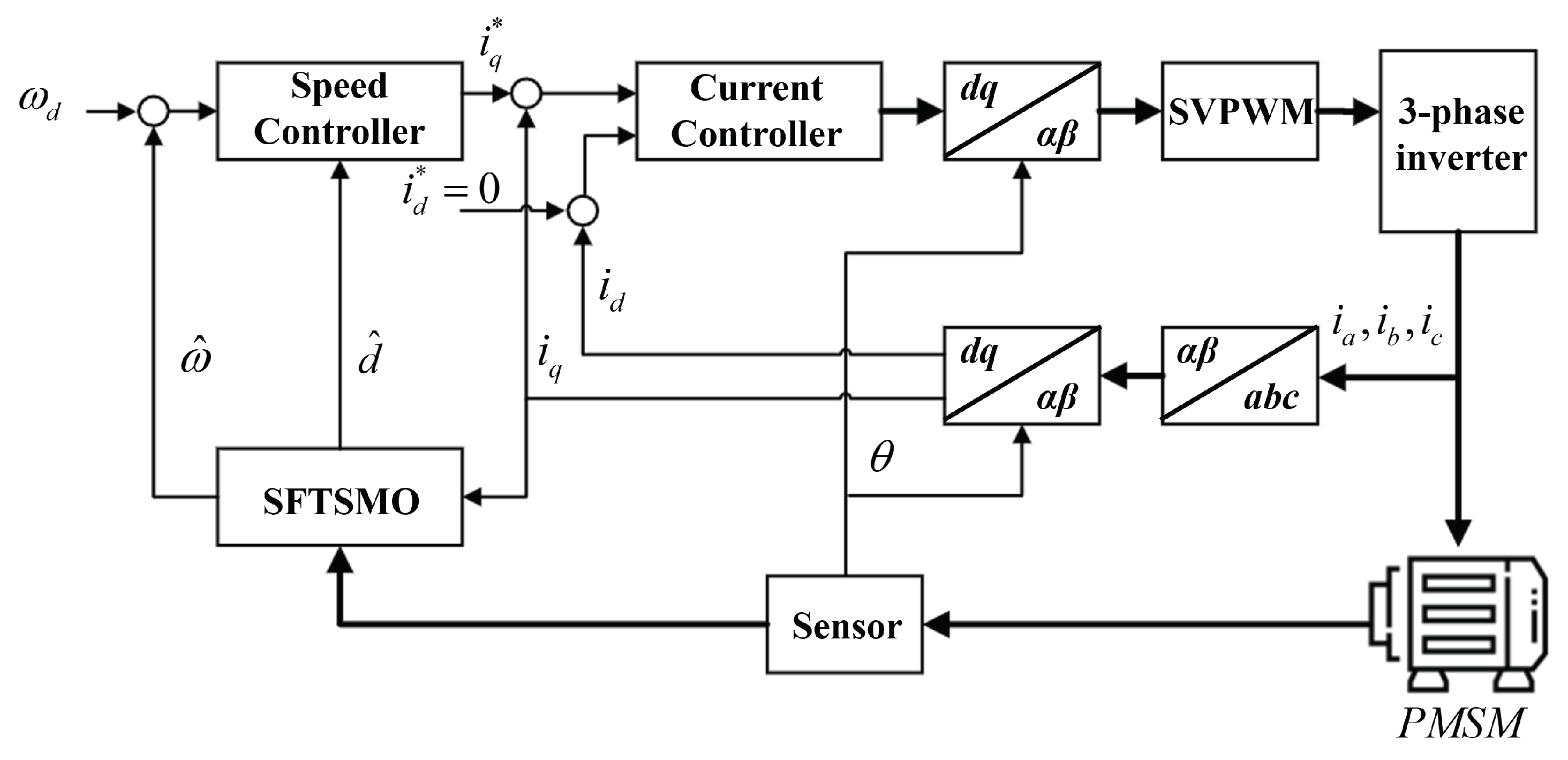
3. Mathematical Model of PMSM and Control Schemes

3.1. PMSM Electrical Model

The PMSM’s high-performance motor control features smooth rotation over the entire motor speed range, maximum torque control at zero speed, and fast acceleration and deceleration. Field-oriented control (FOC) techniques are used for PMSM to achieve control, which derives PMSM’s high accuracy and efficiency. Based on the FOC technique, the three-phase current, which refers to the abc coordinates of the PMSM, can be transformed into a two-phase current on dq rotating coordinates using the Clark/Park transformation. Figure 2 shows the block diagram of FOC based-PMSM speed control [12]. The stator voltage ( u d , u q ) equations of the PMSM control system in dq coordinates are written as Equation (18). In this paper, the model equations are based on a surface-mounted PMSM (SPMSM). The SPMSM has the same value for d- and q-axis inductance ( L d = L q = L s ) according to a permanent magnet that is placed around the rotor and has a constant thickness [30].
u d = r i d ω L s i q + L s d i d d t , u q = r i q + ω L s i d + ω φ + L s d i q d t ,
where i d , i q represent the d- and q-axis stator currents, respectively. r is the resistance, and φ is the flux linkage of the permanent magnet. The measurement speed of the PMSM is expressed as ω . The electromagnetic torque ( T e ) generated by the SPMSM depends on the flux linkage, the number of pole pairs ( n p ) , and inductances. Based on the uniform inductance values of the SPMSM, the equation that expresses T e of the PMSM can be briefly represented as follows [31]:
T e = 3 2 n p φ i q + ( L d L q ) i d i q = 3 2 n p φ i q .
A general PMSM control system is established based on the principle of FOC control, as shown in Figure 5. Under the vector control strategy, i d * is set to zero to decouple the speed and current. Equation (20) shows the mechanical dynamics of the PMSM system [32]
θ ˙ = ω , J ω ˙ + B ω + T L = T e ,
where θ represents the rotor angle of the PMSM. J , B , and T L denote the rotational inertia, viscous friction coefficient, and load torque, respectively.

3.2. Design of the PMSM Sliding Mode Controller Using the Adaptive Quick Reaching Law

Under the occurrence of disturbance and parametric uncertainty, the mechanical modeling of the PMSM can be converted by combining Equations (19) and (20) as follows:
ω ˙ = ( χ + Δ χ ) i q ( η + Δ η ) ω ( ε + Δ ε ) T L = χ n i q η n ω + d ,
where χ , η , and ε represent 3 n p 2 φ / 2 J , B / J , and n p / J , respectively. Δ χ , Δ η , and Δ ε represent the parameter uncertainties. To represent parameter uncertainty and load torque, the perturbation (d) denotes Δ χ i q Δ η ω ( ε + Δ ε ) T L . To trace the reference angular velocity ( ω r ) on PMSM speed modulation, the tracking error ( e ) is defined as the difference between ω r and the measured angular velocity ( ω ) obtained by an encoder. Based on the tracking error, the integral sliding surface ( s i ) is designed as follows:
s i = e + c 0 t e ( τ ) d τ ,
where c is a positive constant. Under the designed sliding surface with Equation (22), the AQRL-based sliding mode controller input ( i q * ) is set up to reach ω r ,
i q * = 1 χ ω ˙ r d + c e + k 1 ( e a | s | 1 ) + k 2 x 1 2 1 + | x 1 | e b | s | sgn ( s ) .
The control input of Equation (23) is not completely achieved since the unknown lumped perturbation d is included. Therefore, the controller is not a fully stable input [33]. To overcome the system weakness caused by disturbance, the SFTSMO in section III.C is proposed to increase the robustness of the APRL-based SMC.

3.3. Design of a Second-Order Fast Terminal Sliding Mode Observer for PMSM
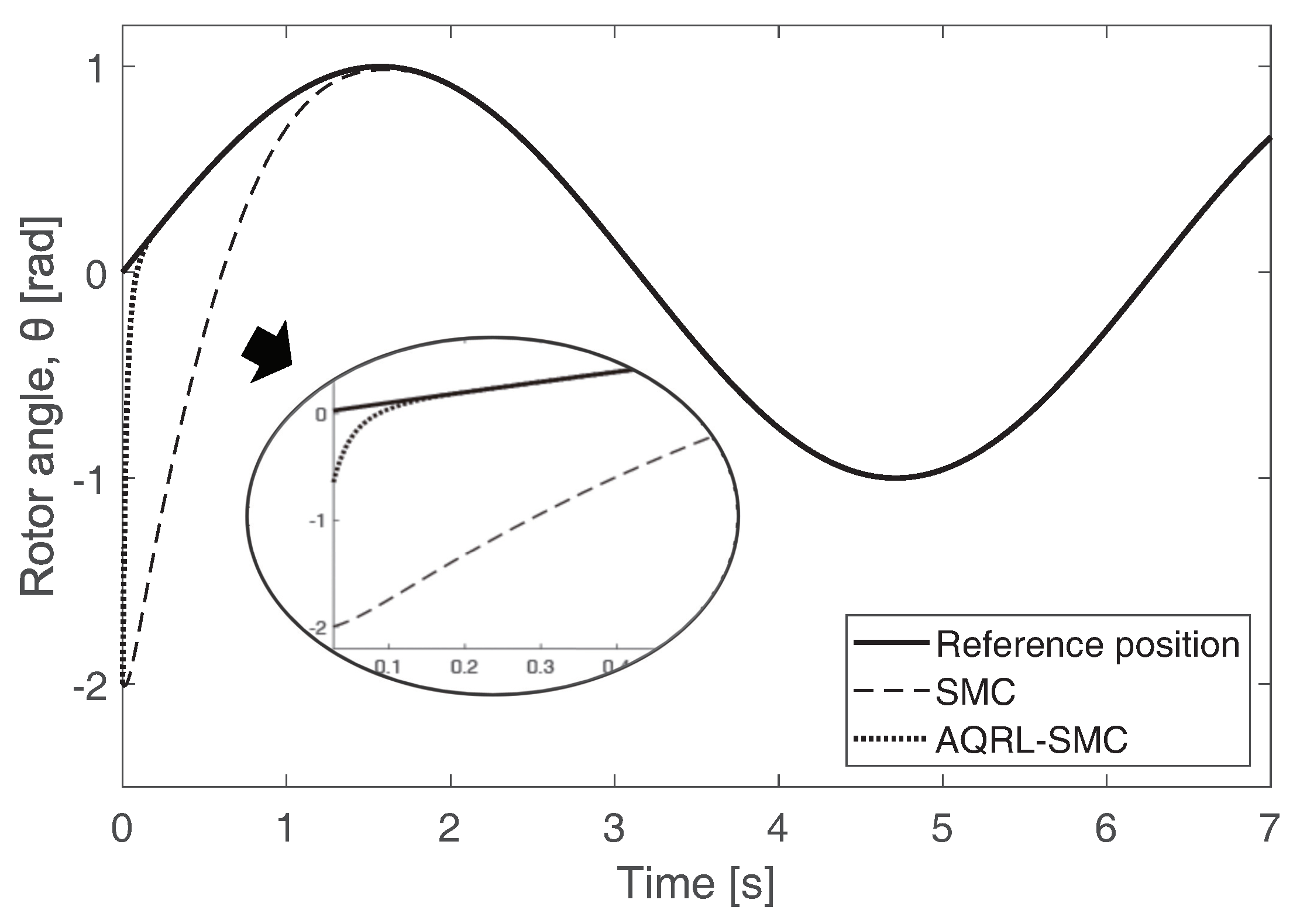
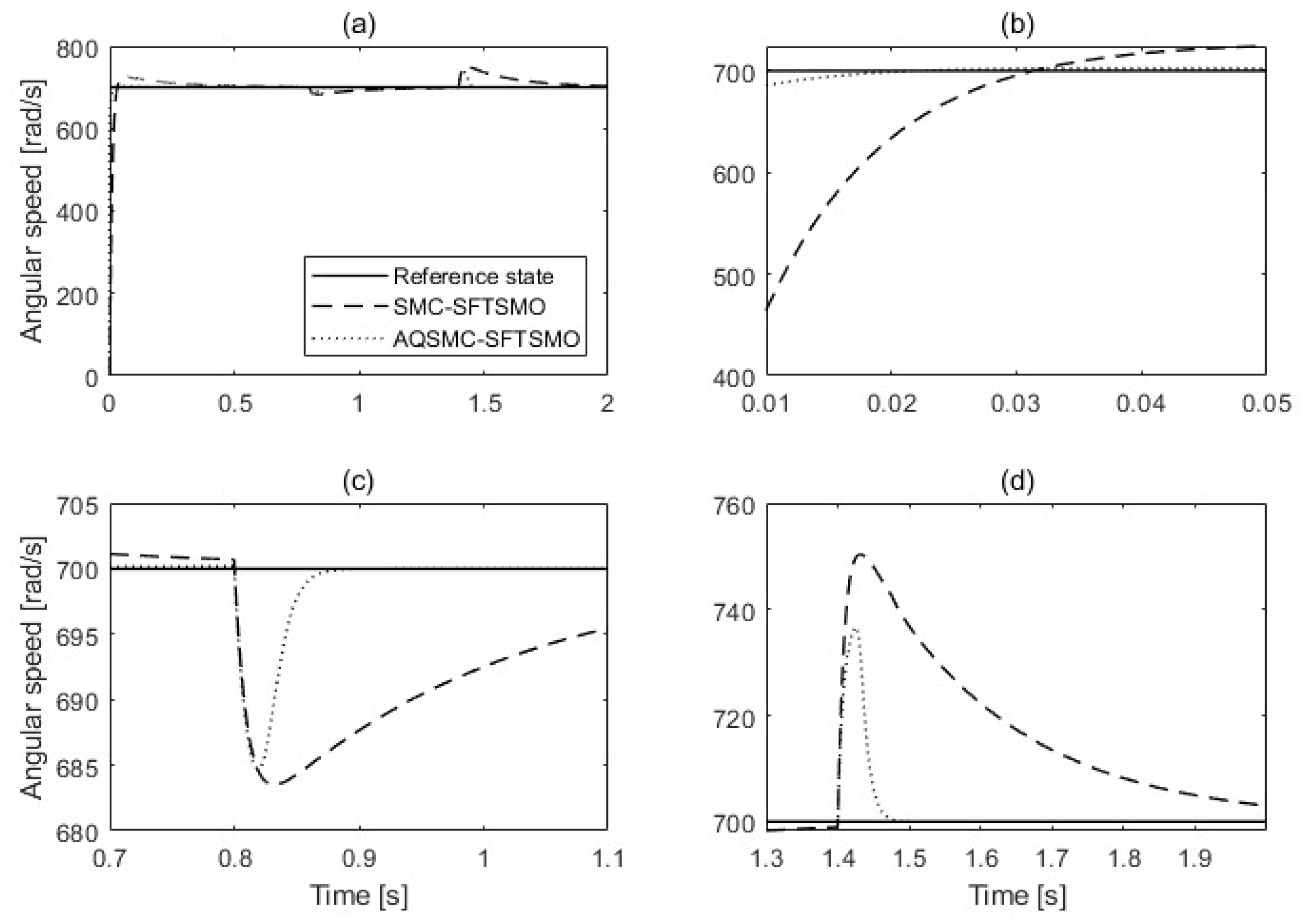
To predict and identify the perturbation accurately under the parameter uncertainty and load torque, a second-order fast terminal sliding mode observer (SFTSMO) is designed as a state equation under Equation (21),
ω ˙ = χ n i q η n ω + d , d ˙ = l ,
where l represents the derivative of the lumped perturbation. Then, the SFTSMO is designed based on the terminal sliding mode,
ω ^ ˙ = χ n i q η n ω ^ + d ^ + u t 1 , d ^ ˙ = u t 2 ,
where ω ^ and d ^ denote the estimated angular velocity of the PMSM and the estimated perturbation, respectively. u t 1 and u t 2 represent the designed control law and lumped disturbance derivative, respectively. The estimated angular velocity error ( ω ˜ ) and estimated disturbance error ( d ˜ ) are derived by subtracting Equation (24) from (25). To reduce the estimation time and achieve better tracking accuracy, the second-order fast terminal sliding surface ( s f t ) is designed for SFTSMO as follows: [34]
s f t = ω ˜ ˙ + ω ˜ + ω ˜ n m ,
where n / m is the rational number under the condition 0 < n / m < 1 . n and m are positive odd numbers. By substituting s f t for Equation (25), the u t 1 is derived as,
u t 1 = ( 1 η n ) ω ˜ + ω ˜ n m + d ˜ s f t .
According to the terminal sliding mode control law [35], the u t 2 is obtained as,
v + q v ˙ = h 1 sgn ( s f t ) , u t 2 = h 2 sgn ( s f t ) ,
where v represents d ˜ s f t and q, h 1 , and h 2 denote the designed positive constants. To prove the stability of the proposed observer, the Lyapunov function shown in Equation (1) is used as follows:
s f t s ˙ f t = s f t ( d h 2 sgn ( s f t ) ) ( h 1 sgn ( s f t ) q v ) , = ( d s f t h 2 s f t ) ( h 1 s f t q v ) < 0 .
Here, h 1 and h 2 satisfy the conditions of h 1 > | q v | and h 2 > d max , respectively. Therefore, the stability of the proposed observer is obtained in a finite time. Under the designed sliding surface as shown in Equation (26), the reaching time t f t taken to reach s f t ( t ) = 0 from initial state s f t ( 0 ) 0 is reduced compared to the conventional high-order terminal sliding surface-based observer. The reaching time t o obtained by the high-order terminal sliding surface ( s h = ω ˜ + β ω ˜ n / m ) from s h ( 0 ) 0 to s h ( t ) = 0 is derived in a similar way as in Equation (2) [36]. The difference between t f t and t o is represented as follows:
t f t t o = m ln ω ˜ ( 0 ) m n m + 1 m n m | ω ˜ ( 0 ) | m n m m n .
To prove the reduced reaching time of the designed terminal sliding surface, by applying the exponential function to t f t and t o , Equation (30) is derived as,
e t f t e t 0 = | ω ˜ ( 0 ) | m n m + 1 e | ω ˜ ( 0 ) | m n m 0 .
The reaching time reduction is proved as in Equation (31). Under the terminal sliding mode control law, estimated disturbance ( d ^ ) is obtained by integrating the u t 2 value. Therefore, the proposed SFTSMO ensures a smooth disturbance observation since u t 2 equals to h 2 sgn ( s f t ) . From the obtained d ^ , the controller input is converted as,
i q * = 1 χ ω ˙ r d ^ + k 1 ( e a | s | 1 ) + k 2 x 1 2 1 + | x 1 | e b | s | + c e .
Therefore, the robustness of the controller input is obtained from the estimated disturbance for the PMSM control system.

4. Simulation

This section describes the simulations carried out using the conventional SMC and the AQRL-based SMC (AQSMC) with SFTSMO in the PMSM speed regulation system to verify the effectiveness of the proposed PMSM speed controller design method. The PMSM system was established based on a block diagram, as shown in Figure 2, using MATLAB/Simulink. The numerical SPMSM parameters used for the simulation are denoted in Table 1. Moreover, we set the control parameters of a , b , c , k 1 , k 2 , h 1 , h 2 , n , m , and Q in the simulations as 0.1, 0.5, 100, 5, 2.4, 1, 10, 11, 13, and 100, respectively. Three types of simulations were performed to confirm the advantage of the SMC: position tracking, sudden speed shift, and sudden load disturbance of the SPMSM.
Figure 6 shows the position error between the measured rotor position signal of the PMSM and the reference position signal represented by a sine function with respect to time. The bold line represents the reference position signal. In this position tracking simulation, we conducted the simulation using a different sliding surface, s p = e ˙ 1 + c 1 e 1 , where e 1 denotes the positional error between the ideal position signal ( θ d ) and measured position signal ( θ ) with c 1 = 15 . The position controlled system is θ ¨ ( t ) = f ( θ , t ) + ε u ( t ) + δ ( t ) in which f ( θ , t ) = 25 θ , ε = 133 , and δ ( t ) = 10 sin ( π t ) with an assumption that the ideal position signal is θ d = sin ( t ) . The initial position is set up as 2 . To follow the reference position signal, we induced u ( t ) = c 1 ( θ ˙ d θ ˙ ) + θ ¨ + f ( θ , t ) + g ( θ , s 1 ) · s g n ( s 1 ) c 1 ( θ ˙ d θ ˙ ) + θ ¨ + f ( θ , t ) + g ( θ , s 1 ) · s g n ( s 1 ) ε ε as the AQSMC-based control input. The AQSMC indicated by the thick dotted line has a faster tracking time than the conventional SMC.
Figure 7 shows the tracking angular speed when the reference speed changes suddenly. The reference speed changes for three intervals to compare the speed tracking performance between the conventional SMC and QSMC. The thin black dashed line and thick dotted line indicate the speed responses based on the SMC and the AQSMC, respectively. The initial speed of the PMSM, which is represented as a thin solid line, started at zero and reached the target value of 700 rad/s. At t = 0.2 s and t = 0.45 s, the desired speeds were converted to 400 and 800 rad/s, respectively. The conventional SMC and QSMC have no overshoot on the system, while the controller works to reach the desired speed; however, the error of the QSMC-based PMSM speed controller, which occurred between the reference angular speed and measured angular speed of the SPMSM, decreases faster than the conventional SMC. Moreover, the settling time and rising time are smaller than the conventional SMC for all changes in the reference angular speed. We can therefore verify that the AQSMC has better performance than the conventional SMC.
Figure 8a–d show the speed tracking performances when a sudden load disturbance occurs. To prove the performance of the proposed reaching law and SMDO, the simulation was proceeded by the SFTSMO-based SMC and the SFTSMO-based AQSMC for equitable comparison. The reference speed was fixed at 700 rad/s. In Figure 8, the thin dashed and thick dotted lines denote the angular speed of the SFTSMO-based SMC and the SFTSMO-based AQSMC, respectively. Figure 8a shows that the SFTSMO-based QSMC has a reduced settling and rising time and less overshoot compared with the SFTSMO-based SMC. Figure 8c shows the SFTSMO performance in the presence of the external disturbance and load torque. In the simulation, the sudden load disturbances T L = 2 N·m and T L = −4 N·m were added at t = 0.8 s and t = 1.4 s until the simulation ended, respectively. The SFTSMO-based AQSMC proved to be more robust against sudden disturbance and quickly recovered to the desired speed compared to the conventional SMC. Therefore, we can confirm that the performance of the SFTSMO-based AQSMC is better than that of the SFTSMO-based SMC for handling disturbance in the PMSM speed regulation system.

5. Conclusions

In this paper, we proposed an AQRL-based PMSM speed controller for a robust speed control PMSM system and SFTSMO to estimate the disturbance and parameter uncertainty. We set up a model according to an FOC-based SPMSM system. To improve the robustness of the PMSM control system, we designed an AQRL based on an exponential function and power equation to overcome the trade-off between the reaching time and chattering phenomenon. Moreover, to deal with perturbations such as load torque and parameter uncertainty, the SMDO was proposed. To enhance the estimation performance and reduce the estimation time, we suggested SFTSMO, which is based on a second-order terminal sliding surface. We derived the adaptive control input i q * using QSMC and SFTSMO. We confirmed and proved the increased performance of a speed control system driven by QSMC with SFTSMO.

Author Contributions

This paper was accomplished by all the authors. H.A., Y.C. and K.Y. conceived the idea, performed the analysis, and designed the simulation; J.P., S.K. and M.H. carried out the numerical simulations; and H.A., S.K. and K.Y. co-wrote the manuscript. All authors have read and agreed to the published version of the manuscript.

Funding

This work was supported by the National Research Foundation of Korea (NRF) grant funded by the Korea government (MSIP) (NRF-2019R1A2C1002343) and the BK21 FOUR Project.

Institutional Review Board Statement

Not applicable.

Informed Consent Statement

Not applicable.

Data Availability Statement

Data are contained within the article.

Conflicts of Interest

The authors declare no conflicts of interest.

Abbreviations

Abbreviations represented in this paper:
PMSMpermanent magnet synchronous motor
PIproportional-integral
SMCsliding mode control
AQRLadaptive quick reaching law
SMDOsliding mode disturbance observer
HOTSMOhigh-order terminal sliding mode observer
SFTSMOsecond-order fast terminal sliding mode observer
SISOsingle-input single-output
CRLconventional reaching law
FOCfield-oriented control
SPMSMsurface-mounted PMSM
AQSMCAQRL- based SMC

References

  1. Fodorean, D.; Sarrazin, M.; Marţiş, C.; Anthonis, J.; Auweraer, H. Electromagnetic and structural analysis for a surface-mounted PMSM used for light-EV. IEEE Trans. Ind. Appl. 2016, 52, 2892–2899. [Google Scholar] [CrossRef]
  2. Kefalas, T.; Kladas, A. Thermal investigation of permanent-magnet synchronous motor for aerospace applications. IEEE Trans. Ind. Electron. 2014, 61, 4404–4411. [Google Scholar] [CrossRef]
  3. Fung, R.; Kung, Y.; Wu, G. Dynamic analysis and system identification of an LCD glass-handling robot driven by a PMSM. Appl. Math. Model. 2010, 34, 1360–1381. [Google Scholar] [CrossRef]
  4. Li, S.; Liu, Z. Adaptive speed control for permanent-magnet synchronous motor system with variations of load inertia. IEEE Trans. Ind. Electron. 2009, 56, 3050–3059. [Google Scholar]
  5. Pisano, A.; Davila, A.; Fridman, L.; Usai, E. Cascade control of PM DC drives via second-order sliding-mode technique. IEEE Trans. Ind. Electron. 2008, 55, 3846–3854. [Google Scholar] [CrossRef]
  6. Liu, H.; Li, S. Speed control for PMSM servo system using predictive functional control and extended state observer. IEEE Trans. Ind. Electron. 2012, 59, 1171–1183. [Google Scholar] [CrossRef]
  7. Fuentes, E.; Silva, C.; Kennel, R. MPC implementation of a quasi-time-optimal speed control for a PMSM drive, with inner modulated-FS-MPC torque control. IEEE Trans. Ind. Electron. 2016, 63, 3897–3905. [Google Scholar] [CrossRef]
  8. Pajchrowski, T.; Zawirski, K. Application of artificial neural network to robust speed control of servodrive. IEEE Trans. Ind. Electron. 2007, 54, 200–207. [Google Scholar] [CrossRef]
  9. Pajchrowski, T.; Zawirski, K.; Nowopolski, K. Neural speed controller trained online by means of modified RPROP algorithm. IEEE Trans. Ind. Inform. 2015, 11, 560–568. [Google Scholar] [CrossRef]
  10. Chang, Y.; Chen, C.; Zhu, Z.; Huang, Y. Speed control of the surface-mounted permanent-magnet synchronous motor based on Takagi–Sugeno fuzzy models. IEEE Trans. Power Electron. 2016, 31, 6504–6510. [Google Scholar] [CrossRef]
  11. Yu, J.; Shi, P.; Zhao, L. Finite-time command filtered backstepping control for a class of nonlinear systems. Automatica 2018, 92, 173–180. [Google Scholar] [CrossRef]
  12. Mohd Zaihidee, F.; Mekhilef, S.; Mubin, M. Robust speed control of PMSM using sliding mode control (SMC)—A review. Energies 2019, 12, 1669. [Google Scholar] [CrossRef]
  13. Zhang, B.; Pi, Y.; Luo, Y. Fractional order sliding-mode control based on parameters auto-tuning for velocity control of permanent magnet synchronous motor. ISA Trans. 2012, 51, 649–656. [Google Scholar] [CrossRef]
  14. Liu, Y.; Wang, X. Speed global integral sliding mode control with a load sliding mode observer for PMSM. IEICE Electron. Express 2018, 15, 20171270. [Google Scholar]
  15. Liu, X.; Yu, H.; Yu, J.; Zhao, L. Combined speed and current terminal sliding mode control with nonlinear disturbance observer for PMSM drive. IEEE Access 2018, 6, 29594–29601. [Google Scholar] [CrossRef]
  16. Leu, V.; Choi, H.; Jung, J. Fuzzy sliding mode speed controller for PM synchronous motors with a load torque observer. IEEE Trans. Power Electron. 2012, 27, 1530–1539. [Google Scholar] [CrossRef]
  17. Qian, R.; Luo, M.; Sun, P. Improved nonlinear sliding mode control based on load disturbance observer for permanent magnet synchronous motor servo system. Adv. Mech. Eng. 2016, 8, 1687814016642670. [Google Scholar] [CrossRef]
  18. Merabet, A. Cascade second order sliding mode control for permanent magnet synchronous motor drive. Electronics 2019, 8, 1508. [Google Scholar] [CrossRef]
  19. Roy, S.; Baldi, S.; Fridman, L. On adaptive sliding mode control without a priori bounded uncertainty. Automatica 2020, 111, 108650. [Google Scholar] [CrossRef]
  20. Niu, Y.; Ho, D.; Lam, J. Robust sliding mode control for uncertain stochastic systems with time-varying delay. Automatica 2005, 41, 873–880. [Google Scholar] [CrossRef]
  21. Utkin, V. Discussion aspects of high-order sliding mode control. IEEE Trans. Automat. Control 2016, 61, 829–833. [Google Scholar] [CrossRef]
  22. Wang, Y.; Li, B.; Yan, F.; Chen, B. Practical adaptive fractional-order nonsingular terminal sliding mode control for a cable-driven manipulator. Int. J. Robust Nonlinear Control 2018, 29, 1396–1417. [Google Scholar] [CrossRef]
  23. Faieghi, M.; Delavari, H.; Baleanu, D. Control of an uncertain fractional-order Liu system via fuzzy fractional-order sliding mode control. J. Vib. Control 2012, 18, 1366–1374. [Google Scholar] [CrossRef]
  24. Hall, C.; Shtessel, Y. Sliding mode disturbance observer-based control for a reusable launch vehicle. J. Guid. Control Dyn. 2006, 29, 1315–1328. [Google Scholar] [CrossRef]
  25. Woldegiorgis, A.; Ge, X.; Li, S.; Hassan, M. Extended sliding mode disturbance observer-based sensorless control of IPMSM for medium and high-speed range considering railway application. IEEE Access 2019, 7, 175302–175312. [Google Scholar] [CrossRef]
  26. Lee, K.; Kim, S.; Kwak, S.; You, K. Quadrotor stabilization and tracking using nonlinear surface sliding mode control and observer. Appl. Sci. 2021, 11, 1417. [Google Scholar] [CrossRef]
  27. Mobayen, S. An adaptive chattering-free PID sliding mode control based on dynamic sliding manifolds for a class of uncertain nonlinear systems. Nonlinear Dyn. 2015, 82, 53–60. [Google Scholar] [CrossRef]
  28. Wang, Y.; Feng, Y.; Zhang, X.; Liang, J.; Cheng, X. New reaching law control for permanent magnet synchronous motor with extended disturbance observer. IEEE Access 2019, 7, 186296–186307. [Google Scholar] [CrossRef]
  29. Xiu, C.; Guo, P. Global terminal sliding mode control with the quick reaching law and its application. IEEE Access 2018, 6, 49793–49800. [Google Scholar] [CrossRef]
  30. Murakami, H.; Honda, Y.; Kiriyama, H.; Morimoto, S.; Takeda, Y. The performance comparison of SPMSM, IPMSM and SynRM in use as air-conditioning compressor. In Proceedings of the Conference Record of the 1999 IEEE Industry Applications Conference, 34th IAS Annual Meeting, Phoenix, AZ, USA, 3–7 October 1999; Volume 2, pp. 840–845. [Google Scholar]
  31. Xu, W.; Junejo, A.; Liu, Y.; Islam, M. Improved continuous fast terminal sliding mode control with extended state observer for speed regulation of PMSM drive system. IEEE Trans. Veh. Technol. 2019, 68, 10465–10476. [Google Scholar] [CrossRef]
  32. Li, S.; Zhou, M.; Yu, X. Design and implementation of terminal sliding mode control method for PMSM speed regulation system. IEEE Trans. Ind. Inform. 2013, 9, 1879–1891. [Google Scholar] [CrossRef]
  33. Zhang, X.; Sun, L.; Zhao, K.; Sun, L. Nonlinear speed control for PMSM system using sliding-mode control and disturbance compensation techniques. IEEE Trans. Power Electron. 2013, 28, 1358–1365. [Google Scholar] [CrossRef]
  34. Abolvafaei, M.; Ganjefar, S. Maximum power extraction from a wind turbine using second-order fast terminal sliding mode control. Renew. Energy 2019, 139, 1437–1446. [Google Scholar] [CrossRef]
  35. Feng, Y.; Han, F.; Yu, X. Chattering free full-order sliding-mode control. Automatica 2014, 50, 1310–1314. [Google Scholar] [CrossRef]
  36. Yu, X.; Zhihong, M. Fast terminal sliding-mode control design for nonlinear dynamical systems. IEEE Tran. Circuits Syst. I Fundam. Theory Appl. 2002, 49, 261–264. [Google Scholar]
  37. Kim, Y.; Ahn, H.; Hu, M.; You, K. Improved non-singular fast terminal sliding mode control for SPMSM speed regulation. IEEE Access 2023, 11, 65924–65933. [Google Scholar] [CrossRef]
Figure 1. System trajectory of the conventional and adaptive sliding mode reaching laws. (a) Conventional reaching law; (b) adaptive reaching law.
Actuators 13 00136 g001
Figure 2. Closed−loop state response of the conventional and adaptive quick reaching laws.
Actuators 13 00136 g002
Figure 3. Control input comparison between the conventional and adaptive quick reaching laws.
Actuators 13 00136 g003
Figure 4. The phase trajectory using the conventional reaching law and the adaptive quick reaching law.
Actuators 13 00136 g004
Figure 5. Block diagram of PMSM speed control.
Actuators 13 00136 g005
Figure 6. Tracking performance comparison between the SMC and the AQRL−based SMC.
Actuators 13 00136 g006
Figure 7. Speed tracking performance between the SMC and the AQRL-based SMC.
Actuators 13 00136 g007
Figure 8. Control performance comparison between the SMC and the QSMC with SFTSMO.
Actuators 13 00136 g008
Table 1. Numerical parameters of the SPMSM model [37].
ParameterValueUnit
R s 2.4 Ω
L s 0.65[mH]
φ 0.003[Wb]
J0.004 × 10 4 [kg· m2]
B0.004 × 10 4 [N· m· s/rad]
n p 4
Disclaimer/Publisher’s Note: The statements, opinions and data contained in all publications are solely those of the individual author(s) and contributor(s) and not of MDPI and/or the editor(s). MDPI and/or the editor(s) disclaim responsibility for any injury to people or property resulting from any ideas, methods, instructions or products referred to in the content.

