Article

A Novel Thermal Deformation Self-Stabilization Flexible Connection Mechanism

1
State Key Laboratory of Precision Electronic Manufacturing Technology and Equipment, Guangdong University of Technology, Guangzhou 510006, China
2
School of Engineering, University of Warwick, Coventry CV4 7AL, UK
*
Author to whom correspondence should be addressed.
Actuators 2024, 13(4), 146; https://doi.org/10.3390/act13040146
Submission received: 19 March 2024 / Revised: 12 April 2024 / Accepted: 12 April 2024 / Published: 15 April 2024
(This article belongs to the Section Actuators for Manufacturing Systems)

Abstract

:
In micro-LED chip repair, a nanopositioner is commonly used to adjust the positioning of the LED chip. However, during the bonding process, the heat generated can cause the positioning system to deform, leading to inaccurate alignment and poor-quality chip repair. To solve this issue, a novel flexible connection structure has been proposed that can eliminate thermal deformation. The principle of this novel flexible connection structure is that the thermal distortion self-elimination performance is achieved via three flexible connection modules (FCM) so that the thermal stress is automatically eliminated. First, the paper introduces the principle of thermal deformation elimination, and then the design and modeling process of the proposed structure are described. A heat transfer model is then developed to determine how temperature is distributed within the structure. A thermal deformation model is established, and the size of the FCM is optimized using a genetic algorithm (GA) to minimize the thermal deformation. Finite element analysis (FEA) is used to simulate and evaluate the thermal distortion self-elimination performance of the optimized mechanism. Finally, experiments are conducted to verify the reliability and accuracy of the simulation results. The simulations and experiments show that the proposed structure can eliminate more than 38 % of the thermal deformation, indicating an excellent thermal deformation self-eliminating capability.

1. Introduction

The advent of electronic display screens has transformed the way we experience the world around us. These displays will be critical in future intelligent information transfer, enabling various applications in national defense, military, and other fields [1,2,3,4]. However, the conventional LCD, OLED, and mini/micro-LED displays exhibit varying performance characteristics [5]. LCDs are widely used in daily life due to their cost-effectiveness. However, they rely on backlight light-emitting processes and require the adjustment of liquid crystal molecules in the electric field for modulation. This results in displays that can only achieve milliseconds of response speed, relatively low luminous efficiency, and contrast [6]. OLED displays utilize organic light-emitting diodes for self-illumination, offering excellent bending performance, increased display viewing angles, and brighter adjustments. However, such displays are limited by the drawbacks of their organic light-emitting material, which significantly reduces their service life [7,8,9].
The mini/micro-LED displays are a new and improved technology that uses tiny LED chips to create individual pixels. These displays are very efficient, use less power, have better contrast and response times, and are more durable. Because of these benefits, they are expected to become the standard for the next generation of displays [10,11,12]. These mini/micro-LED displays are still in the development phase, and there are some technical challenges to overcome, such as chip preparation, mass transfer, detection, and repair [10,12].
Mass transfer is a necessary process in the fabrication of micro-LED panels. There are two main methods for micro-LED mass transfer: direct monolithic integration and indirect pick-and-place [13,14]. Once the chips are grown on a source substrate, they must be detached and relocated to the target substrate or driver circuit board using precision equipment [15]. For 4K HDTV, which contains approximately 25 million chips ranging from 3 to 10 mm in size, precise chip placement is crucial. The placement accuracy must reach 1 mm, and the throughput must exceed 100 million units per hour(UPH) to achieve a yield exceeding 99.9999% [16]. For 8K displays, the chip count escalates to 100 million, making it even more challenging to transfer and assemble the micro-LED chips. To ensure a robust bond between the chips, the substrate must undergo heating [5,6].
During long-term high-temperature operation, the rigid bolt-connected platform experiences self-heating and expansion, resulting in platform warping, depression, and reduced positioning accuracy during mass transfer [17,18]. Therefore, eliminating the warping and depression caused by heating the nanopositioner and improving the positioning accuracy during the mass transfer is an urgent problem that needs to be solved.
In recent years, concepts similar to thermal deformation self-elimination have mostly appeared in the field of precision equipment [19,20,21,22], and optics [23,24,25]. In precision equipment, Lee presented an air-bearing stage that utilizes a four-bar linkage flexure to compensate for yaw motion while maintaining both the high structural stiffness of the stage and the extremely low rotational stiffness of the flexure [19]. Jia et al. [20] proposed a novel decoupled flexure nanopositioner with a thermal distortion self-elimination function. They were the first to propose applying the principle of thermal deformation self-elimination to nanopositioners. Chun presented a novel approach to mitigate the thermal effects in flexure mechanism-based nanopositioning systems by introducing fluid flow (air or water) through the internal fluidic channels of the compliant structure [21]. Wang provided a new design strategy for the sandwiched metastructure with zero thermal-induced warping, high load-bearing capability, and high resonant frequency, exhibiting a negligible out-of-plane thermal-induced warping, reduced by 99.8% [22]. High-quality optical devices used in space require precise manufacturing to minimize thermal deformation caused by prolonged exposure to light. Liu applied mesh deformation to optimize the flexure for high force–thermal stability in a space mirror. The surface shape error is reduced by 22% [23]. Guo et al. [24] proposed a hybrid ball-hinged secondary mirror assembly (HSMA) to achieve thermal adaptation over a wide temperature range. Based on exact constraint principles, Huo proposed a novel kinematic flexure mount comprising three identical chains [25]. However, the thermal characteristics of the flexure mechanism applied in precision equipment still need to be studied further.
To achieve a better thermal deformation self-elimination heat ability, a thermal deformation self-eliminating flexible connection module(FCM) is proposed in this study, replacing the rigid bolt connection and utilizing elastic deformation to eliminate thermal deformation. The performance of the FCM is investigated through temperature field analysis, thermal deformation modeling analysis, and experimental tests. Finally, the simulations and experiments show that the proposed structure can eliminate more than 38 % of the thermal deformation.

2. Flexible Connection Mechanism

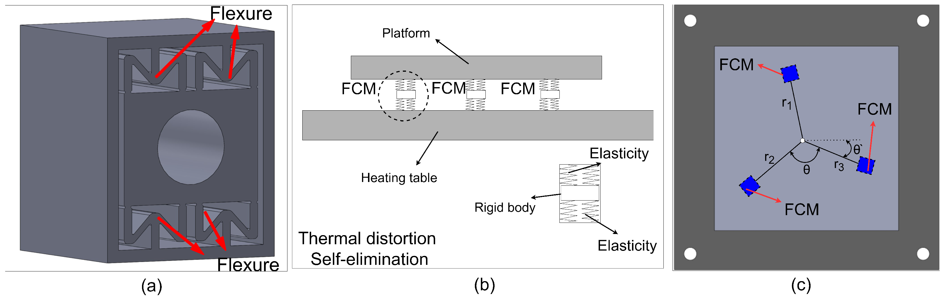
2.1. Thermal Distortion Self-Elimination Principle
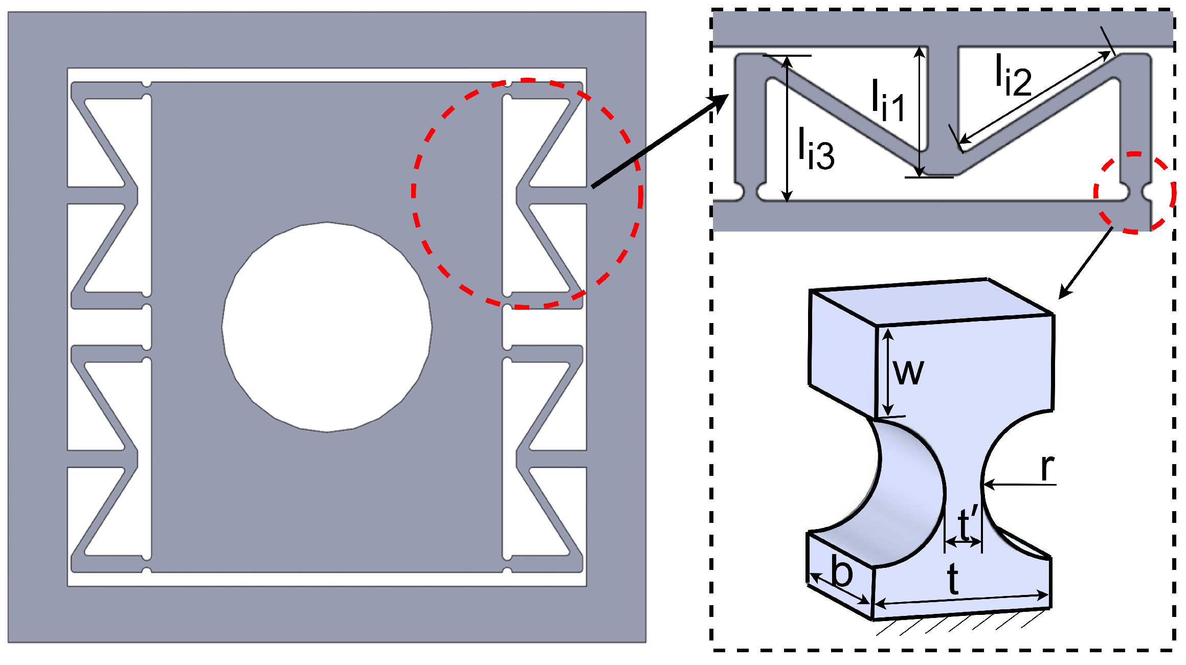
During the process of bonding micro-LED, it is necessary to heat the substrate. However, this high-temperature process can cause thermal errors in the rigid bolt connection mechanism. The mechanism might self-heat and expand, leading to the warping or denting of the nanopositioner [20]. The overall structure of FCM is shown in Figure 1a, which is symmetrical and has a threaded hole. In this paper, elastic deformation of FCM is used to eliminate heat deformation. Its principle is shown in Figure 1b. Thermal stress and thermal deformation of the nanopositioner are represented by red arrows and red dots. Three sets of FCMs can be installed rotationally symmetrically—two sets of FCMs cannot balance the thermal stress in all directions, while three sets of FCMs can achieve a better balance of thermal stress with the least amount of material—to keep the center of the nanopositioner in an almost constant position. F t 1 , F t 2 , and F t 3 are the forces produced by the three sets of FCMs counteracting the thermal stress in their direction. The distribution of FCMs in the nanopositioner and the overall view of the nanopositioner are shown in Figure 1c.

2.2. Design of FCM

The FCM module is specifically designed to eliminate thermal deformation. The module features an 18 mm diameter, and three FCMs are positioned around the center of the platform at an optimal angle and radius to ensure that thermal deformation only occurs in the FCMs, as shown in Figure 1a. The module has a symmetrical top-bottom structure consisting of four sets of hyperbolic beam-type flexure hinges, each with a length of 3.5 mm, a width of 5.6 mm, and a thickness of 32 mm. The material of FCM must meet the small deformation when heated, so the thermal expansion rate of the material is small. In addition, FCM requires high flexibility. The aluminum alloy described above is a suitable material for the manufacture of FCM.

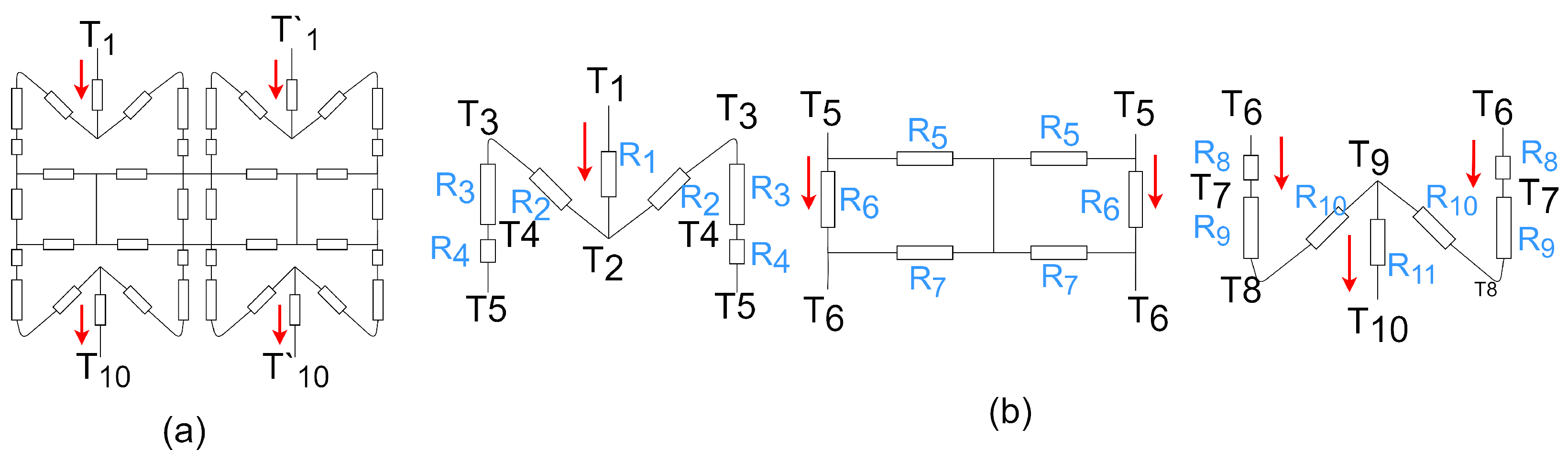
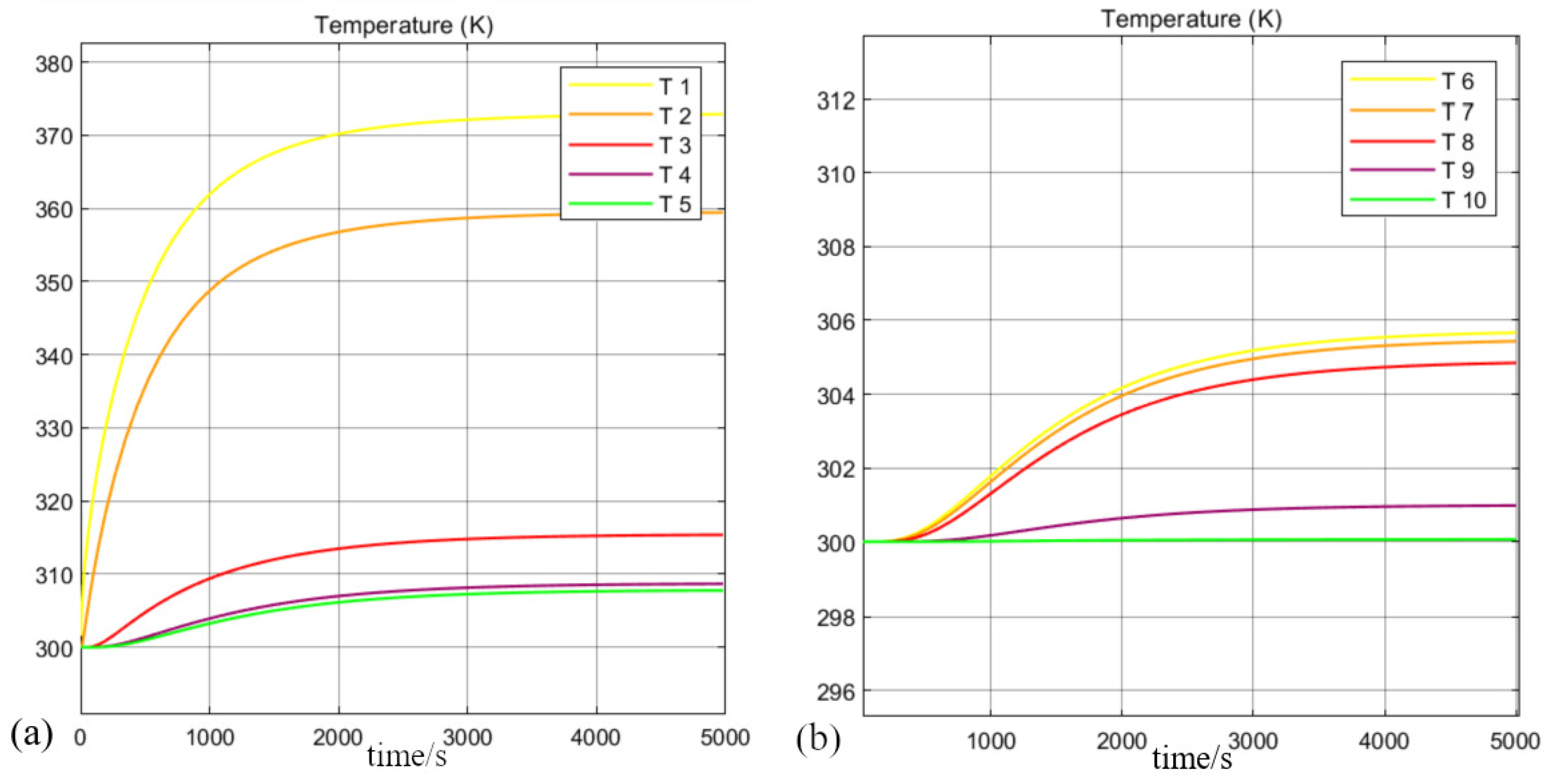
3. Heat Transfer Model of FCM

It is important to conduct a thorough study on the heat transfer within the FCM module as its performance relies heavily on temperature. This can be achieved using a thermal resistance network model to investigate its heat transfer at various temperature levels. By replacing the FCM with multiple thermal resistances, as shown in Figure 2a, we can effectively analyze its heat transfer characteristics.
To simplify the model-solving process, the thermal resistance network model has been divided into three parts (see Figure 2b). This simplifies the analysis and reduces the model’s complexity.
According to the principle of heat transfer, when the temperature difference between the front and back of a single thermal resistance is Δ T (the change in Δ T takes Δ t (s) time), the heat Q flowing through this thermal resistance is:
Q = λ S / δ · T 1 T 2 = λ S / δ · Δ T = G · Δ T = Δ T / R
parameter description: λ (W/(m· K)): the thermal conductivity, S ( m 2 ) : thermal conductivity area, δ (m): thermal conductivity wall thickness, G (W/K): equivalent thermal conductivity, R (K/W): thermal resistance, Δ T (K): temperature difference of a single thermal resistance.
The amount of heat absorbed within a single thermal resistance over a period of time Δ t can be calculated using the following formula:
Q = ρ c Δ V T 2 t T 2 0 Δ t
The establishment of the thermal resistance network model is based on the conservation of energy. In the absence of heat loss, a single thermal resistance transfers as much heat as it absorbs. However, for a single thermal resistance to transfer the same amount of energy as it absorbs, it needs to pass through the same amount of time. So Equations (1) and (2) both experience time Δ t (s). So, according to the energy conservation theorem, it can be expressed as:
G · Δ T = ρ c Δ V T 2 t T 2 0 Δ t
please note the following variables: T 2 t (K) represent the temperature of wall 2 at t seconds, T 2 0 (K) represent the initial temperature of wall 2, ρ ( kg / m 3 ) represent density of thermal resistance, c ( J / ( kg · K ) ) represent specific heat capacity of thermal resistance, Δ V ( m 3 ) represent the volume of a single thermal resistance.
Using Equation (3), the objective function of the simplified thermal resistance model of FCM has been established.
n = 1 4 G n T n t T n + 1 t = ρ c n = 1 4 Δ V n T n + 1 t T n + 1 0 Δ t G 6 G 5 + G 7 G 5 + G 6 + G 7 · T 5 t T 6 t = ρ c Δ V 6 T 6 t T 6 0 Δ t n = 6 9 G n T n t T n + 1 t = ρ c n = 6 9 Δ V n T n + 1 t T n + 1 0 Δ t
parameter conditions: T 1 = 370 K, ρ = 2770 kg / m 3 and c = 880 J / kg · K , G n : equivalent thermal conductivity of the nth thermal resistance, V n : the volume of the nth thermal resistance. The result of the solution is shown in Figure 3.

4. FCM Mechanism Optimization and FEA

In this section, the relationship between the deformation of FCM and the center displacement of the nanopositioner is established. Then, the FCM size is optimized by taking the minimum displacement of the center of the nanopositioner as the objective function.

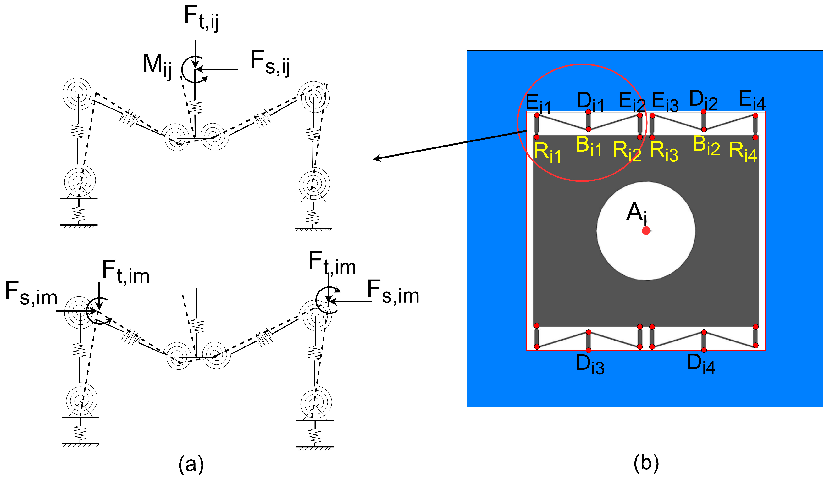
4.1. Modeling of FCM with Thermal Distortion Self-Elimination

As the temperature of the nanopositioner increases, the thermal stress on the FCMs increases. The FCM will then deform. A deformation trend of the FCM is shown in Figure 4a. The flexure endpoint D i j is connected to the exterior through a straight beam, and the relationship between force and displacement at this point can be expressed as follows [26]:
Δ x i j Δ y i j Δ z i j Δ θ x , i j Δ θ y , i j Δ θ z , i j = c 11 0 0 0 0 0 0 c 22 0 0 0 c 25 0 0 c 33 0 c 35 0 0 0 0 c 44 0 0 0 0 c 53 0 c 55 0 0 c 62 0 0 0 c 66 F x , i j F y , i j F z , i j M x M y M z
parameter description: Δ x i j (mm): the tension and compression displacement, Δ y i j (mm): shear displacement, Δ θ i j ( ° ) : rotation angle, F t , i j (N): tension force, F s , i j (N): shear force, M i j ( N · m ) : torque, c i : the flexibility coefficient of straight beam deflection.
Temperature change causes elastic deformation of the straight beam, and therefore, the flexibility coefficient matrix can be listed as follows [26]:
c 11 = l 1 k E b t c 22 = 4 l 1 3 E b 3 k t + 3 l 1 2 k G b t c 33 = 4 l 1 3 k E b t 3 + 3 l 1 2 k G b t c 44 = b l 1 k 2 G b t 3 c 55 = 12 l 1 k 3 E b t 3 c 66 = 12 l 1 k 3 E b 3 t c 26 = c 62 = 6 l 1 2 k 2 E b 3 t c 35 = c 53 = 6 l 1 2 k E b t 3
please note the following variables: E = 72 GPa, b (thickness of FCM) = 50 mm, l 1 (mm): the length of D i j B i j , t(mm): the width of the straight beam D i j B i j .
According to the knowledge related to thermodynamics, k can be expressed as:
k = ( 1 + α Δ T )
where α is the coefficient of thermal expansion, and Δ T is the change in temperature.
The flexure hinge inside the FCM is connected to a straight beam E i j R i j , and the force and displacement relationships at the endpoints E i j of the straight beam are as follows:
Δ t i m Δ s i m Δ θ i m = c x , F X 0 0 0 c y , F Y c y , M Z 0 c θ , F Y c θ , M Z F t , i m F s , i m M i m
parameter description: Δ x i m (mm): the tension and compression displacement, Δ y i m (mm): shear displacement, Δ θ i m ( ° ) : rotation angle, F t , i m (N): tension force, F s , i m (N): shear force, M i m ( N · m ) : torque, c i : the flexibility coefficient of straight beam deflection.
The compliance coefficients c of the circular flexure hinged straight beam under thermal stress can be listed as [27]:
c x , F X = 1 E w f 4 c y , F Y = 12 E w t 2 f 1 2 t f 2 + f 3 c θ , F Y = c y , M Z = 12 E w t f 1 f 2 c θ , M Z = 12 E w f 1
where E and w are Young’s modulus and the length of the free end. f 1 , f 2 , f 3 , f 4 are calculated as follows [27]:
f 1 = f 10 + f 11 f 2 = f 20 + f 21 f 3 = f 30 + f 31 f 4 = f 40 + f 41
f 10 = π 2 0 r sin φ + r cos φ ( 2 b + t 2 r cos φ ) 3 d φ f 11 = 0 π 2 r sin φ + r cos φ ( 2 b + t 2 r cos φ ) 3 d φ f 20 = π 2 0 r sin φ ( r sin φ + r cos φ ) ( 2 b + t 2 r cos φ ) 3 d φ f 21 = 0 π 2 r sin φ ( r sin φ + r cos φ ) ( 2 b + t 2 r cos φ ) 3 d φ f 30 = π 2 0 r 2 sin 2 φ ( r sin φ + r cos φ ) ( 2 b + t 2 r cos φ ) 3 d φ f 31 = 0 π 2 r 2 sin φ ( r sin φ + r cos φ ) ( 2 b + t 2 r cos φ ) 3 d φ f 40 = π 2 0 r sin φ + r cos φ 2 b + t 2 r cos φ d φ f 41 = 0 π 2 r sin φ + r cos φ 2 b + t 2 r cos φ d φ
Finally, the position coordinates have been established, and the thermal drift model is determined by finding the relationship between the coordinates of each node. In Figure 4b, the locations of the points D, B, E, and R are shown. Let the center point of the FCM be represented by A i , and the center point of the nano-displacement platform be represented by O o . Due to the deformation of the flexure and the change in position, the constraint point D i j moves to D i j , and the free points B i j , E i m , and R i m move to B i j , E i m , and R i m . The distances | D i j B i j | = l 1 , | R i m E i m | = l 3 , | D i j O o | = r i , and | D i 1 D i 3 | = m . According to the linear expansion model of solid matter, the position relationship can be expressed as follows [20]:
x B i j x D i j y B i j y D i j = k x B i j x D i j y B i j y D i j + Δ x i j Δ y i j
x E i m x B i m y E i m y B i j = k x E i m x B i j y E i m y B i j
x R i m x E i m y R i m y E i m = k + Δ t i m l 3 x R i m x E i m y R i m y E i m + Δ s i m m x R i 1 x R i 2 y R i 1 y R i 2
x R i m x A i y R i m y A i = k x B i m x A i y B i m y A i
The thermal deformation equation is used to describe how the center position of flexure-free endpoints changes. This change happens after a temperature change and is measured relative to the center of the nanopositioner in the global coordinate system [20]:
x D i j Δ x y D i j Δ y = k cos Δ θ sin Δ θ sin Δ θ cos Δ θ x D i j y D i j
the parameter Δ x represents the displacement of the nanopositioner center along the X-axis, Δ y represents the displacement of the nanopositioner center along the Y-axis, and Δ θ represents the deflection angle at the center of the nanopositioner [20]. When the variation in angle Δ θ is minimal, it can be denoted by a linear expression. To achieve a harmonious ratio between the equations and parameters, the static equilibrium equations of the nanopositioner within FCMs are as follows [20]:
i = 1 3 j = 1 4 ( F t , i j + F s , i j ) = 0
i = 1 3 j = 1 4 ( F t , i j + F s , i j ) × O D i j + i = 1 3 j = 1 12 M i j = 0
m = 1 8 ( F t , i m + F s , i m + F t , i j + F s , i j ) = 0 , i = 1 , 2 , 3
m = 1 8 F t , i m + F s , i m × R i m E i m + m = 1 8 M i m = 0 , i = 1 , 2 , 3
Finally, the thermal distortion model of the nanopositioner has been established. The position matrix parameters x D i j , y D i j , Δ x i j , Δ y i j , F t , i j , F s , i j and M i j ( i = 1 , 2 , 3 ; j = 1 , 2 , 3 , 4 ) are selected as unknown. It can be obtained from the above linear equations that the other parameters are the design sizes of the nanopositioner.

4.2. Parameters Optimization

The position sizes of the FCM are r 1 , r 2 , r 3 , θ and m, as shown in Figure 1b. The FCM structure sizes are l 1 , l 2 , l 3 , b, r, w, t and t, as shown in Figure 5. The above size parameters need to be optimized to improve thermal distortion elimination performance and ensure the position accuracy of the nanopositioner. Considering the size of the nanopositioner and the convenience of calculation, we set b = 20 mm and the value range of r 1 , r 2 , and r 3 to 40–50 mm. FCM uses a 3D printing process. Therefore, the range of FCM parameters must meet the processing range. In addition, the parameter range needs to match the design of the nanopositioner. After meeting the above parameter requirements, finite element simulation is carried out on the preliminarily established nanopositioner. By constantly adjusting the parameters, the better parameter range of thermal deformation self-elimination is determined. So, the value ranges of m, l 1 , l 2 , l 3 , r, w, t and t are determined by the preliminary finite element simulation analysis. The nanopositioner’s displacement and rotation angle may be affected by thermal distortion. The center position displacement can be represented by Δ x and Δ y , while the rotation angle displacement is Δ θ . To eliminate the effects of thermal distortion, here we take the total linear displacement Δ L x y as the optimization goal. Therefore, the optimization problem can be stated as:
min Δ L x y = Δ x 2 + Δ y 2
optimization parameters: r i , θ , m, l i , w, t, t .
According to the preliminary finite element simulation, the parameters obtained are: 0 ° θ 20 ° , 50 mm r i 70 mm , 4 mm m 8 mm , 2 mm l i 5 mm , 2 mm w 5 mm , 0.4 mm t 0.8 mm , 0.3 mm t 0.6 mm . Other constraints that help in the calculation are: bending strength condition of flexure hinge: S σ i j , max σ y , condition of nanopositioner center angle under temperature load: Δ θ 0 . 5 ° .
MATLAB GA toolbox was used to complete the optimization task. In the process of GA, the number of iterations is set to 50 steps. The optimal sizes of the nanopositioner are shown in Table 1.

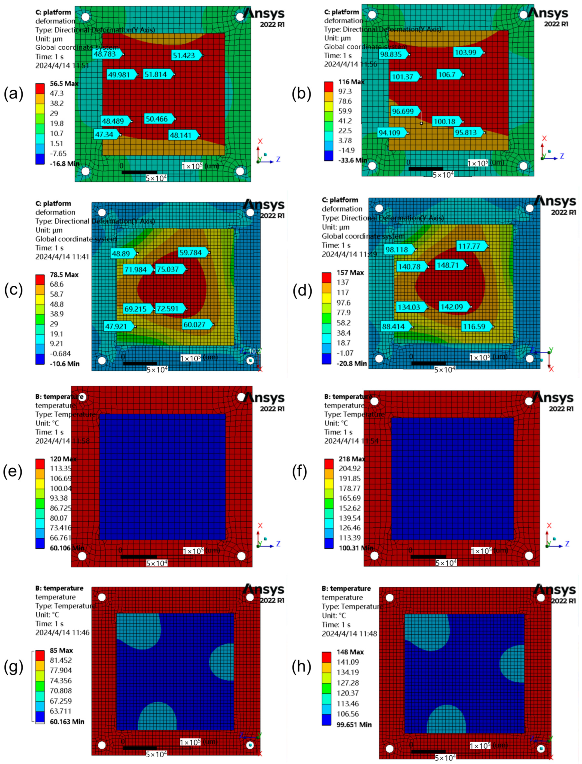
4.3. Simulation Analysis of FCM Thermal Distortion Self-Elimination Performance

ANSYS Workbench 2022 R1 was used to analyze the thermal distortion self-elimination performance of FCM. The simulation process and results are described below. The initial temperature for the simulation was set to 293 K, and the temperature loads on the base of the nanopositioner were set to 333 K and 373 K, respectively.
Two simulation models were developed: (a) a static positioning platform fixed with FCM (which did not take into account when the platform was in motion); and (b) static positioning platforms fixed with rigid bolts. The boundary conditions for simulation were set, including a convection coefficient between the mechanism and the air of 10 W / ( m 2 · K ) , a thermal radiation coefficient of 0.55, and temperature loads of 333 K and 373 K on the positioning platform. The simulation yielded the thermal deformation of the two models under different thermal loads (see Figure 6c,d,g,h). Finally, the positioning platform warpage of the two models was calculated (see Figure 6a,b,e,f).
From the simulation results, it can be seen that the warpage of the positioning platform fixed with rigid bolts was 50%, while the warpage of the positioning platform fixed with FCM was only 12%. Comparing the two, it shows that FCM was able to eliminate 38% of the warpage of the positioning platform.

5. Experiments and Discussion

In this section, we first designed the deformation experiments of the positioning platform under various thermal environments and comparatively verified that the thermal distortions produced by the FCM at thermal loads of 323 K, 343 K, and 363 K are 56.8%, 32.0%, and 33.2% of those produced by the rigid connecting mechanism at the same thermal loads.
Then, the deformation experiment was simulated, and the corresponding simulation data were obtained. Finally, the experimental data and the simulation data were compared, and it was found that the error between them did not exceed 10%.

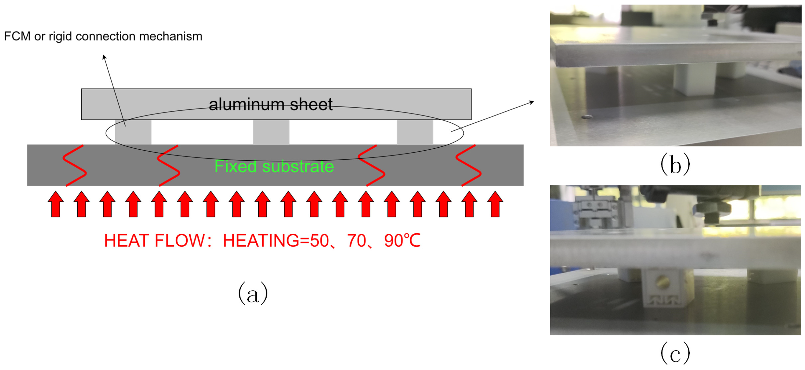
5.1. Experimental Setup

During this experiment, a substrate platform was firmly established, and a heating table was positioned underneath it to efficiently heat the surface, as shown in Figure 7a. Three FCMs were evenly distributed on the substrate, supporting an aluminum plate with a specific weight(see Figure 7b). The experimental protocol dictated that the heating table raise the substrate’s temperature to a predetermined level, subsequently transferring the heat to the FCMs, inducing thermal deformation. Subsequently, the displacement of the aluminum plate at four designated points was meticulously gauged. Following this initial measurement, the FCMs were replaced with a rigid connection mechanism that differed slightly in overall dimensions(see Figure 7c), and the procedure was replicated to assess the aluminum plate’s deformation displacement at the same four points under varying temperature conditions.

5.2. Experimental Instruments

The experimental tools employed in this study encompass eddy current sensors, thermal imaging devices, and temperature-controlled heating tables. The specific types of these instruments are detailed in Table 2.

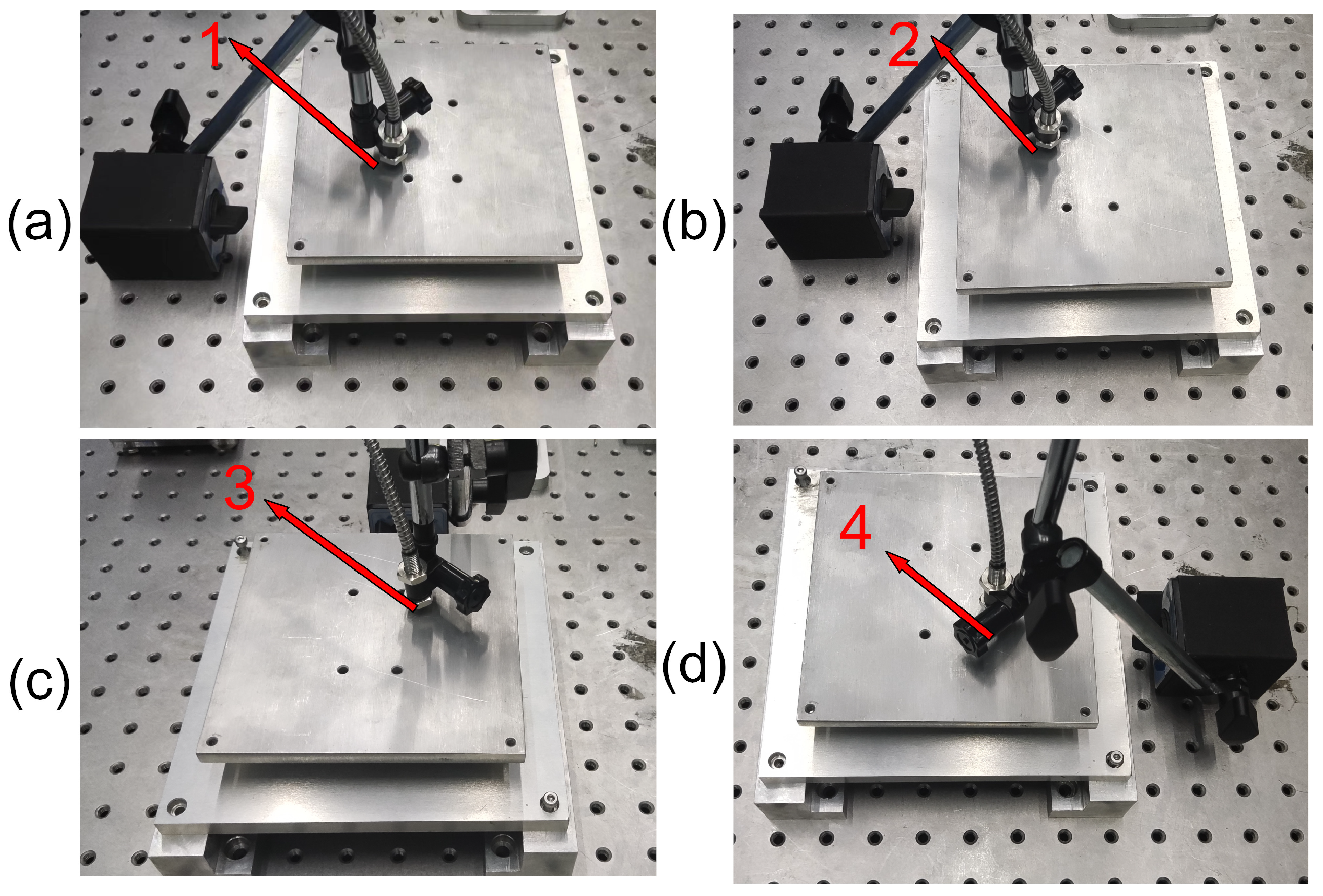
5.3. Experimental Procedure

The first step was to keep the temperature-controlled heating table still. After that, the positioning platform was firmly fixed to the table with bolts. Next, the accuracy and efficiency of the eddy current sensor were tested to meet the requirements of the experiment. The sensor was then fixed to the workbench with a fixing bracket.
After fixing the eddy current sensor, position its probe in the positioning platform to measure the position of point 1. Keep the probe parallel to its performance and maintain a spacing of about 1 mm. Next, open the temperature control platform and set the heating temperature to 323 K and 373 K, respectively. Once the measured surface temperature reaches 323 K and 373 K, respectively, record the readings on the voltmeter. Upon completion of the measurement at point 1, close the temperature control table and wait for the whole platform to cool down naturally. Repeat the process described in Figure 8 to measure points No. 2, No. 3, and No. 4 and record the experimental data.

5.4. Experimental Data Processing and Result Analysis

After the experiment was completed, the data were integrated as shown in Table 3.
Upon careful consideration of the experimental data calculations, it is evident that the FCM effectively eliminates thermal distortion-induced deformation displacement. Specifically, when exposed to thermal loads of 323 K, 343 K, and 363 K, the thermal distortion generated by the FCM mechanism is reduced to 56.8%, 32.0%, and 33.2% of that observed in the rigid connection mechanism under identical thermal conditions. This substantial reduction underscores the FCM’s potential in addressing thermal distortion, further validating its reliability and utility in practical applications.

6. Conclusions

A novel self-eliminating mechanism for thermal deformation in nanopositioners was designed, modeled, and optimized to address the challenges associated with thermal distortion. The thermal resistance network model was established to analyze the internal temperature variations within the FCM when exposed to heat. A genetic algorithm (GA) was employed to refine the dimensions of the FCM. Through rigorous simulations, the performance of the optimized FCM in eliminating thermal deformation was evaluated. The results demonstrated that the FCM exhibited a significant reduction in thermal deformation compared to the rigid connection mechanism, achieving reductions of 56.8%, 32.0%, and 33.2% at thermal loads of 323 K, 343 K, and 363 K, respectively. Furthermore, the accuracy of the simulations was verified through experiments, revealing a discrepancy of less than 10%.

Author Contributions

F.F. conceived the idea and designed the structure. F.F. and Z.L. completed the theoretical analysis. F.F., Z.L. and H.T. contributed to data analysis and interpretation. F.F. and Z.L. wrote the paper, and all authors provided feedback. All authors have read and agreed to the published version of the manuscript.

Funding

This research was funded by the Natural Science Foundation of China under Grant 52305597, Science and Technology Projects in Guangzhou under Grant SL2022A04J01372, and funded by State Key Laboratory of Precision Electronic Manufacturing Technology and Equipment under Grant JMDZ202313, in part by the European Unions Horizon 2020 research and innovation program under the Marie Sklodowska-Curie Grant Agreement No. 101026104, Engineering Technology Center of Guangdong General University under Grant 2022GCZX005.

Data Availability Statement

Data available on request from the authors.

Conflicts of Interest

The authors declare no conflict of interest.

References

  1. Liang, Q.; Sun, Y.; Wang, L.; Liu, M. A Novel Inertial-Aided Visible Light Positioning System Using Modulated LEDs and Unmodulated Lights as Landmarks. IEEE Trans. Autom. Sci. Eng. 2022, 19, 3049–3067. [Google Scholar] [CrossRef]
  2. Murthy, L.; Mukhopadhyay, A.; Yellheti, V.; Arjun, S.; Biswas, P. Evaluating Accuracy of Eye Gaze Controlled Interface in Military Aviation Environment. In Proceedings of the 2020 IEEE Aerospace Conference, Big Sky, MT, USA, 7–14 March 2020. [Google Scholar]
  3. Wei, Z.; Li, M.; Liu, Z.; Wang, Z.; Zhang, C.; Chen, C.J.; Wu, M.C.; Yang, Y.; Yu, C.; Fu, H. Parallel Mini/Micro-LEDs Transmitter: Size-Dependent Effect and Gbps Multi-User Visible Light Communication. J. Light. Technol. 2022, 40, 2329–2340. [Google Scholar] [CrossRef]
  4. Alimova, D.; Efimov, I.; Kharkin, D. Methods of Reducing the Intensity of Specular Reflections of LCD Modules for Aviation Applications. In Proceedings of the 2020 International Multi-Conference on Industrial Engineering and Modern Technologies (FarEastCon), Russky, Island, 6–7 October 2020; pp. 1–5. [Google Scholar] [CrossRef]
  5. Wu, Y.; Ma, J.; Su, P.; Zhang, L.; Xia, B. Full-Color Realization of Micro-LED Displays. Nanomaterials 2020, 10, 2482. [Google Scholar] [CrossRef]
  6. Zhou, X.; Tian, P.; Sher, C.W.; Wu, J.; Liu, H.; Liu, R.; Kuo, H.C. Growth, transfer printing and colour conversion techniques towards full-colour micro-LED display. Prog. Quantum Electron. 2020, 71, 100263. [Google Scholar] [CrossRef]
  7. Koden, M. OLED Displays and Lighting; John Wiley & Sons: Hoboken, NJ, USA, 2017. [Google Scholar]
  8. Askari, M.B. OLED Display Technology. Am. J. Opt. Photonics 2014, 2, 32–36. [Google Scholar] [CrossRef]
  9. Tsukamoto, Y.; Umeda, T.; Mizusaki, M.; Shibasaki, M.; Uetake, N.; Kawato, S.; Shimada, S. Mass Production Technology of Flexible AMOLED Displays and Improvement of the OLED Device Characteristics. In Proceedings of the 2019 26th International Workshop on Active-Matrix Flatpanel Displays and Devices (AM-FPD), Kyoto, Japan, 2–5 July 2019; Volume 26, pp. 1–2. [Google Scholar] [CrossRef]
  10. Chen, Z.; Yan, S.; Danesh, C. Topical Review MicroLED technologies and applications: Characteristics, fabrication, progress, and challenges. J. Phys. D Appl. Phys. 2021, 54, 123001. [Google Scholar] [CrossRef]
  11. Bai, J.; Niu, P.; Cao, S. Highly precise measurement of depth for μLED based on single camera. Measurement 2022, 89, 110439. [Google Scholar] [CrossRef]
  12. Huang, Y.; Tan, G.; Gou, F.; Li, M.C.; Lee, S.L.; Wu, S.T. Prospects and challenges of mini-LED and micro-LED displays. J. Soc. Inf. Disp. 2019, 27, 387–401. [Google Scholar] [CrossRef]
  13. Li, J.; Tang, H.; Zhu, Z.; He, S.; Gao, J.; He, Y.; Chen, X. Hybrid Position/Force Fully Closed-Loop Control of a Flip-Chip Soft-Landing Bonding System. IEEE Trans. Ind. Electron. 2022, 69, 9235–9245. [Google Scholar] [CrossRef]
  14. Li, P.; Tao, J.; Zhao, Y.; Sun, Y.; Fan, K.; Zhu, L.; Sun, W.; Lv, J.; Qin, Y.; Wang, Q.; et al. Flexible Quantum-Dot Color-Conversion Layer Based on Microfluidics for Full-Color Micro-LEDs. Micromachines 2022, 13, 448. [Google Scholar] [CrossRef]
  15. Niu, P.; Sun, H.; Zhaofeng, L.; Qiang, L.; Shinan, C.; Haitao, T. Design And Force Analysis of The Chip Transfer Platform for Mass Transfer. In Proceedings of the 2021 18th China International Forum on Solid State Lighting & 2021 7th International Forum on Wide Bandgap Semiconductors (SSLChina: IFWS), Shenzhen, China, 6–8 December 2021; pp. 143–145. [Google Scholar] [CrossRef]
  16. Pan, Z.J.; Chen, Z.Z.; Jiao, F.; Zhan, J.L.; Chen, Y.Y.; Chen, Y.F.; Nie, J.X.; Zhao, T.Y.; Deng, C.H.; Kang, X.N.; et al. A review of key technologies for epitaxy and chip process of micro light-emitting diodes in display application. Acta Phys. Sin. 2020, 69, 198501. [Google Scholar] [CrossRef]
  17. Tsai, M.Y.; Wang, Y.W. A Theoretical Solution for Thermal Warpage of Flip-Chip Packages. IEEE Trans. Compon. Packag. Manuf. Technol. 2020, 10, 72–78. [Google Scholar] [CrossRef]
  18. Tang, X.; Guo, C.; Wang, K.; Song, D.; Zhang, J.; Qi, W. New Fourier Expansion for Thermal Buckling Analysis of Rectangular Thin Plates with Various Edge Restraints. Arch. Appl. Mech. 2023, 93, 3411–3426. [Google Scholar] [CrossRef]
  19. Lee, H.J.; Ahn, D. Development of Air Bearing Stage Using Flexure for Yaw Motion Compensation. Actuators 2022, 11, 100. [Google Scholar] [CrossRef]
  20. Jia, Y.; Tang, H.; Xu, S.; Xu, Y.; Chen, X.; Tian, Y. A Novel Decoupled Flexure Nanopositioner with Thermal Distortion Self-Elimination Function. IEEE/ASME Trans. Mechatron. 2022, 27, 2953–2962. [Google Scholar] [CrossRef]
  21. Chun, H.; Kim, G.H.; Villarraga-Gómez, H.; Kim, H.Y.; Elwany, A.; Lee, C. Characterization of Thermally Stable Compliant Structures with Internal Fluidic Channels. Precis. Eng. 2020, 66, 201–208. [Google Scholar] [CrossRef]
  22. Wang, H.; Yu, H.; Wang, X.; Zhou, H.; Lei, H.; Chen, M.; Guo, X. Load-Bearing Sandwiched Metastructure with Zero Thermal-Induced Warping and High Resonant Frequency: Mechanical Designs, Theoretical Predictions, and Experimental Demonstrations. Mech. Mater. 2023, 177, 104531. [Google Scholar] [CrossRef]
  23. Liu, F.; Li, W.; Zhao, W.; Wang, X.; Wang, X. Fast Optimization Design of the Flexure for a Space Mirror Based on Mesh Deformation. Photonics 2021, 8, 567. [Google Scholar] [CrossRef]
  24. Guo, L.; Jiang, H.; Lu, Q.; Huang, J.; Zheng, Y.; Zhang, Y.; Zhuang, Y.; Huang, L. Hybrid ball-hinged secondary mirror assembly for high-precision surface shape maintenance. Opt. Express 2023, 31, 22603–22621. [Google Scholar] [CrossRef]
  25. Huo, T.; Yu, J.; Zhao, H. Design of a Kinematic Flexure Mount for Precision Instruments Based on Stiffness Characteristics of Flexural Pivot. Mech. Mach. Theory 2020, 150, 103868. [Google Scholar] [CrossRef]
  26. Wen, S.; Xu, Q. Design of a Novel Piezoelectric Energy Harvester Based on Integrated Multistage Force Amplification Frame. IEEE/ASME Trans. Mechatron. 2019, 24, 1228–1237. [Google Scholar] [CrossRef]
  27. Zhou, Y.; Bai, Z. Research on Thermal Coupling Modeling for Multi-chip Paralleled IGBT Modules Based on Thermal Resistance Network. In Proceedings of the 2023 IEEE 6th International Conference on Information Systems and Computer Aided Education (ICISCAE), Dalian, China, 23–25 September 2023; pp. 407–410. [Google Scholar] [CrossRef]
Figure 1. Thermal deformation self-elimination principle and FCM structure design. (a) the 3D model of an FCM. (b) principle of 3 FCMs. (c) overall view.
Actuators 13 00146 g001
Figure 2. Thermal network models. (a) thermal network model of the FCM. (b) simplified thermal network models.
Actuators 13 00146 g002
Figure 3. Thermal resistance network model-solving results. (a) T1–T5. (b) T6–T10.
Actuators 13 00146 g003
Figure 4. (a) deformation tendency of flexible mechanism under stress. (b) distribution of FCM points.
Actuators 13 00146 g004
Figure 5. Parameters of FCM.
Actuators 13 00146 g005
Figure 6. Thermal deformation of the two models under different thermal loads. (a) thermal warping with FCM under 333 K. (b) thermal warping with FCM under 373 K. (c) thermal warping without FCM under 333 K. (d) thermal warping without FCM under 373 K. (e) temperature distribution with FCM under 333 K. (f) temperature distribution with FCM under 373 K. (g) temperature distribution without FCM under 333 K. (h) temperature distribution without FCM under 373 K.
Actuators 13 00146 g006
Figure 7. Experimental Setup. (a) the experimental diagram. (b) the experimental rigid connection. (c) the experimental FCM.
Actuators 13 00146 g007
Figure 8. Experimental manipulation. (a) experimental measurement point No. 1. (b) experimental measurement point No. 2. (c) experimental measurement point No. 3. (d) experimental measurement point No. 4.
Actuators 13 00146 g008
Table 1. Determination of the optimal sizes of the FCM.
Optimized ParametersRanges of ValuesOptimal Solution Selection
θ [0°, 20°]10°
r 1 [50 mm, 70 mm]64 mm
r 2 [50 mm, 70 mm]64 mm
r 3 [50 mm, 70 mm]64 mm
m[4 mm, 8 mm]6.4 mm
l 1 [2 mm, 5 mm]3 mm
l 2 [2 mm, 5 mm]2.8 mm
l 3 [2 mm, 5 mm]2.8 mm
w[2 mm, 5 mm]2.8 mm
t[0.4 mm, 0.8 mm]0.7 mm
t [0.3 mm, 0.6 mm]0.5 mm
Table 2. Type list of experimental instruments.
Laboratory InstrumentsEddy Current SensorsHandheld Thermal Imaging CameraHeating Platform
Instrument modelML33HIKMICRO H10CH9702
Table 3. Comparison of experiments with and without FCM.
Mechanical DeformationInspection Point 1Inspection Point 2Inspection Point 3Inspection Point 4
50 °C With FCM0.0440.0420.0480.04
50 °C Without FCM0.0910.1010.0980.09
70 °C With FCM0.1120.1220.1060.123
70 °C Without FCM0.1910.1730.1880.180
90 °C With FCM0.1980.2180.1870.209
90 °C Without FCM0.2860.3040.3020.299
Disclaimer/Publisher’s Note: The statements, opinions and data contained in all publications are solely those of the individual author(s) and contributor(s) and not of MDPI and/or the editor(s). MDPI and/or the editor(s) disclaim responsibility for any injury to people or property resulting from any ideas, methods, instructions or products referred to in the content.

