Article

Research on Bearing Mechanism of Spherical Valve Pairs of Axial Piston Pumps

1
State Key Laboratory of Fluid Power Transmission and Control, Zhejiang University, Hangzhou 310001, China
2
China Railway Engineering Equipment Group Co., Ltd., Zhengzhou 450016, China
3
Institute of Advanced Machines, Zhejiang University, Hangzhou 310001, China
*
Author to whom correspondence should be addressed.
These authors contributed equally to this work.
Actuators 2024, 13(4), 147; https://doi.org/10.3390/act13040147
Submission received: 6 February 2024 / Revised: 10 March 2024 / Accepted: 26 March 2024 / Published: 15 April 2024

Abstract

:
The hydraulic system drives the cutter head mechanism to realize the excavation of large tunnel boring equipment, which puts forward the technical requirements of high pressure and large flow to the pump source. The traditional small displacement axial piston pump uses a planar valve plate. However, under high flow and heavy load conditions, the planar valve plate configuration is prone to uneven wear due to the high-pressure and -velocity (PV) value and pressure shock, which ultimately affects the reliability of the system. A simulation analysis of the load-bearing characteristics of the spherical valve plate mechanism is conducted. The Computational Fluid Dynamics (CFD) method was used to construct flow field models for different valve plate oil film structures to calculate differences in their load-bearing capacities. Additionally, the reasons for variations in load-bearing characteristics based on the curvature radius of the spherical valve plate were analyzed. The simulation results demonstrate that the spherical valve plate exhibits superior leak and load-bearing performance compared to the traditional flat valve plate. Furthermore, the curvature radius of the spherical valve plate directly affects the pulsation characteristics of the piston pump. Smaller curvature radii increase the contact area of the oil film, resulting in greater fluctuation in oil film load-bearing, whereas larger curvature radii lead to increased oil film leakage. Using simulation calculations on heavy-load, high-displacement axial piston pumps, it is determined that the optimal curvature radius for stable load-bearing is 350 mm.

1. Introduction

The axial piston pump is widely used in large construction machinery, with the advantages of compact structure, high power density, long life, and so on. For a swashplate-type axial piston pump, the pressure distribution in the high- and low-pressure chambers undergoes abrupt changes during its operational cycle. When the rotor moves from a low-pressure area to a high-pressure area, the residual oil in the dead volume is quickly compressed, causing an instantaneous backflow, which brings a large flow shock in the outlet chamber and generates quite a lot of noise. To decrease the flow shock and operating noise, one of the most useful methods is to optimize the flow distribution structure. Between the valve plate and the cylinder block, there exists an oil film structure, which is one of the three major frictional components in the axial piston pump. It serves to support the cylinder block and valve plate, and it has also been proven to enhance reliability and decrease flow ripple. Therefore, the research on the load-bearing mechanism of the distribution plate is crucial in the design of axial piston pumps.
J.M. Bergada and S. Kumar [1] conducted research on the pressure distribution, forces, torque, and leakage issues between the cylinder block and valve plate in axial piston pumps, analyzing the load-bearing mechanism and leakage characteristics of the distribution components. CHEN et al. [2] analyzed the velocity distribution, pressure distribution, leakage flow rate, and bearing capacity of the fluid in the gap according to the N-S equation in the spherical coordinate system. YANG et al. [3] compared and analyzed the supporting characteristics of the spherical and flat distribution components, conducted simulation analysis on the stress and strain characteristics of distribution plate spherical structures with different radii, and proposed an optimal method for choosing the optimized radius. ZHANG et al. [4] proposed a reliability evaluation method for fatigue cracking and wear degradation of spherical distribution pairs with a certain inclination angle of the piston. YE Shaogan et al. [5]. developed a simulation model for oil film lubrication characteristics of spherical valve plate pairs with conical cylinder blocks and validated the effectiveness of the model using experimental tests. N.P. Mandal et al. [6] developed a methodology for designing a swashplate axial piston pump whose barrel kidneys are wider than the bridges separating the kidney ports on the plate. MENG Guangyao et al. [7] used surface modeling technology to establish the geometric model of whole basin piston pumps based on the spherical port plate pair. In terms of simulation modeling methods, L. Pugi and F. Alfatti [8] proposed a simplified functional method to identify and simulate the response of universal hydraulic devices using limited experimental tests. They introduced piecewise transfer functions with programmed poles to reproduce complex nonlinear behaviors that are difficult to reproduce using simplified models. Based on the results, the spherical port pair in the flow process is proven to be more stable. In the industry, with the advancement of computer simulation technology, CFD simulation technology is increasingly regarded by industry professionals as a means to accelerate mechanism verification and speed up the design iteration of critical product structures [9]. However, the optimal support structure of the spherical plate is the key to the design of the plate structure. Therefore, this paper takes a plunger pump as an example to discuss and analyze the solution of the optimal spherical radius.
In this paper, the loading and distribution characteristics of the spherical distribution component were analyzed. The influence of curvature radius parameters on its pressure-flow characteristics was discussed. Firstly, the simulation model was established and the loading and flow distribution characteristics were calculated. The impact of different oil film structures on the inlet and outlet pressure-flow characteristics was analyzed. Finally, the optimization design principles for spherical distribution components were derived, and the optimized structure was proposed.

2. Analysis of the Load-Bearing Mechanism of Spherical Distribution Components

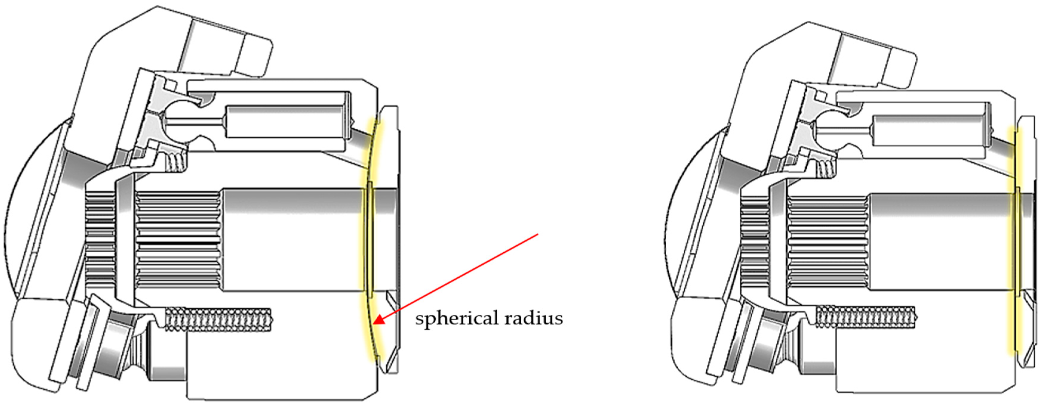
The valve plate is a component of the axial piston pump responsible for distributing high- and low-pressure fluids during operation. In terms of valve plate structure, there are currently two main forms: flat distribution and spherical distribution (Figure 1). As one of the three major frictional pairs in the swashplate-type axial piston pump, the valve plate pair also serves to support the cylinder block and valve plate. Its load-bearing capacity is of utmost importance, effectively preventing rigid contact and frictional losses, while also providing lubrication to enhance the reliability of the distribution structure.
In terms of distribution mechanisms, there is a significant similarity between the distribution mechanisms of flat distribution components and spherical distribution components, both relying on inner and outer concentric sealing rings to provide sealing and auxiliary support. Numerous scholars have extensively discussed the load-bearing mechanism analysis of flat distribution components [10,11]. This paper primarily focuses on the load-bearing mechanism of spherical distribution components. Firstly, based on the fluid continuity equation, it can be determined that the continuity equation in spherical coordinates is as follows:
1 r r ( r 2 u r ) + 1 sin θ θ ( u θ sin θ ) + 1 sin θ u φ φ = 0
where r, θ, and φ represent three directions in the coordinate system.
Based on the gap fluid dynamics of flat distribution components, the gap fluid dynamics N-S equation for spherical distribution components can be rewritten as follows:
F r 1 ρ p r + v F r 0 = d u r d t F θ 1 ρ p θ + v F θ 0 = d u θ d t F φ 1 ρ r sin θ p φ + v F φ 0 = d u φ d t
where Fr0, Fθ0, and Fφ0 are represented as follows:
F r 0 = 2 u r 2 u r r 2 2 r 2 sin θ ( u θ sin θ ) θ 2 r 2 sin θ u r φ F θ 0 = 2 u θ + 2 r 2 u r θ u θ r 2 sin θ cos θ r 2 sin θ u φ φ F φ 0 = 2 u φ + 1 r 2 sin θ u r φ u φ r 2 sin 2 θ + 2 cos θ r 2 sin θ u θ φ
where Fr,θ,φ represent the unit mass forces in the r, θ, and φ directions; ur,θ,φ represent the fluid velocity in the r, θ, and φ directions; p, ρ, and v, respectively, denote pressure, density, and dynamic viscosity.
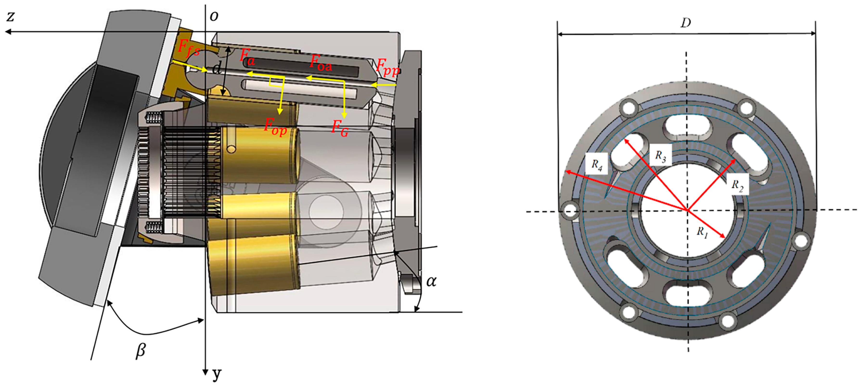
The piston pump layout structure is shown in Figure 2. The piston pump studied in this paper adopts nine pistons, and the pistons are conically distributed in the cylinder block. The primary form of pressure support on the distribution component is manifested as the static pressure support of the oil film. The static pressure support of the sealing rings on the inner and outer sides of the inlet and outlet tapered grooves provides load-bearing capability to the distribution component. The pressure distribution within the inner sealing ring (R1~R2) of the spherical distribution component is as follows [11,12]:
p = p s Δ p t g 2 R 2 t g 2 R + 2 ln ( t g 2 R 2 / t g 2 R ) t g 2 R 2 t g 2 R 1 + 2 ln ( t g 2 R 2 / t g 2 R 1 )
where R1 and R2 represent the inner diameter of the distribution oil groove and the radius of the main shaft seal of the distribution plate, ps is the oil pressure in the distribution groove, pd is the oil pressure in the pump housing, and Δp = pspd.
Similarly, the pressure distribution within the outer sealing ring (R3~R4) is as follows:
p = p s Δ p t g 2 R t g 2 R 3 + 2 ln ( t g 2 R / t g 2 R 3 ) t g 2 R 4 t g 2 R 3 + 2 ln ( t g 2 R 4 / t g 2 R 3 )
where R3 and R4 represent the outer diameter of the distribution oil groove and the radius of the distribution plate, ps is the oil pressure in the distribution groove, pd is the oil pressure in the pump housing, and Δp = pspd.
Leakage model for the spherical valve plate is as follows:
Q 1 = Δ p B 1 φ f e 3 6 μ R
Q 2 = Δ p B 2 φ f e 3 6 μ R
Q 3 = Q 4 = b [ e 3 cos 3 θ 12 μ l Δ p ± v e cos θ 2 ]
where b is the width of the waist groove, b = r3r2, v is the average velocity of the gap flow in the transition zone, v = r0ω, r0 = r3 + (r3r2)/2, h = ecosθ, l is the average length of the gap in the transition zone, which can be considered as the arc length of the circle where r0 is located, l = r0φg, B1 and B2 are the relevant angular coefficients of the spherical valve train, B1 = 1/[tan2θ2 − tan2θ1 + 2ln(tanθ2/tanθ1)], and B2 = 1/[tan2θ4 − tan2θ3 + 2ln(tanθ4/tanθ3)].
Because the relationship between the flow rate, pressure difference, and wall movement velocity is linear, they can be superimposed. When the direction of the rotational speed of the cylinder end is the same as the direction of the liquid flow caused by the pressure difference Δp, the ‘+’ sign is taken, and vice versa, the ‘−’ sign is taken.
The power loss of the clearance in the spherical valve train mainly consists of two parts: one is the flow power loss ΔPQ caused by internal and external leaks of the valve train, and the other is the mechanical friction power loss ΔPm caused by internal friction forces.
P Q = ( Q 1 + Q 2 + Q 3 + Q 4 ) p s
P m = μ A v 2 h
where A is the area of the spherical valve plate.
Assuming ∂(ΔPQ + ΔPm)/∂e = 0, the optimal clearance (emin) for the spherical valve train, where the power loss is minimized (minimum leakage), can be obtained.
e m i n 0 = μ ω Δ p [ 2 π R r 0 3 r 4 ϕ g r 0 ϕ f ϕ g B 1 + B 2 cos θ + b R cos 4 θ ] 1 4
The optimal clearance (emin) of the spherical valve train varies with changes in the hydraulic dynamic viscosity (μ), pump working pressure (Δp), and pump angular velocity (ω). Taking cosθ = 1, the above expression is transformed into the average optimal clearance (eminc0) of the spherical valve train.
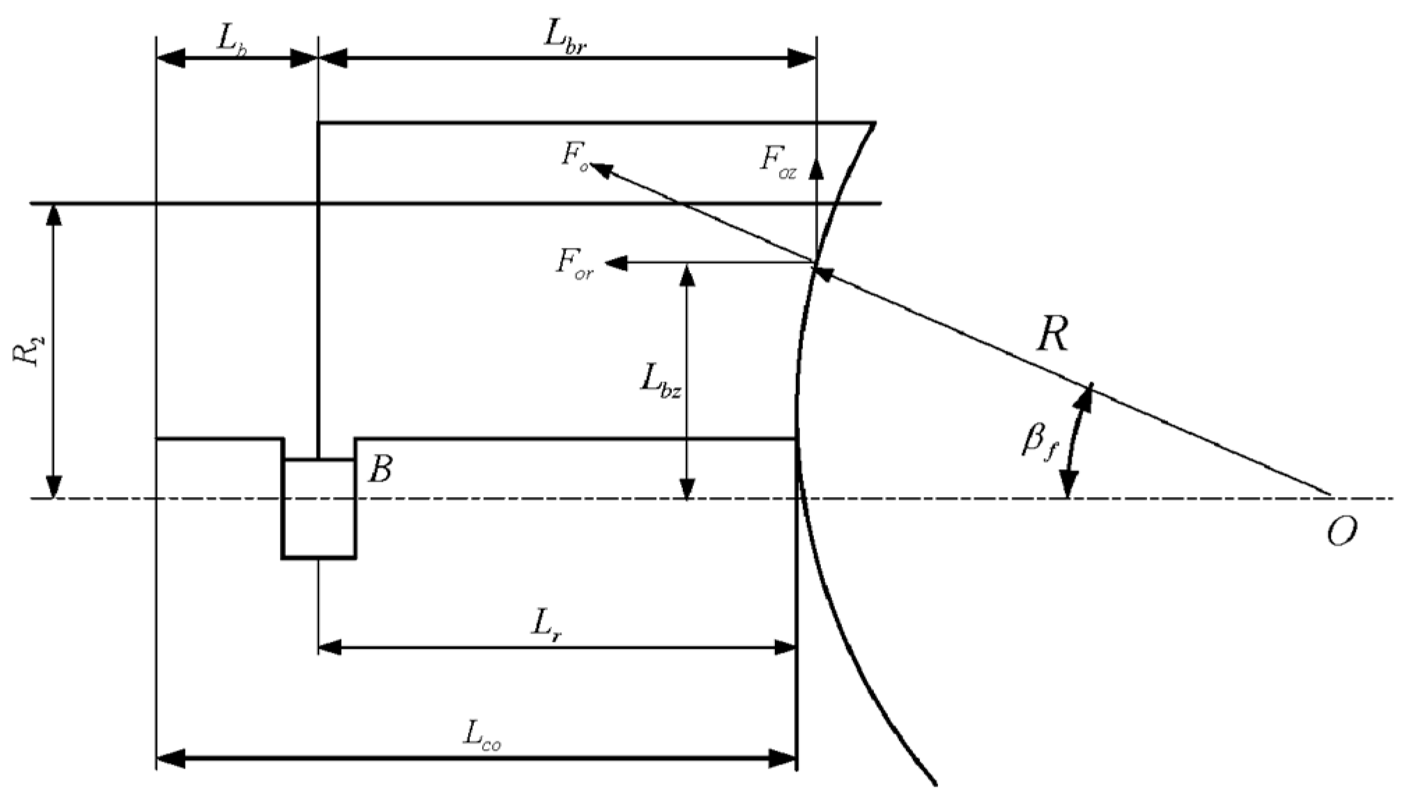
e m i n 0 = K μ ω Δ p
K = [ 2 π R r 0 3 r 4 ϕ g r 0 ϕ f ϕ g B 1 + B 2 cos θ + b R ] 1 4
The reactive force F0 of the liquid in the spherical gap of the spherical valve train can be decomposed into the axial force component Foz along the z-axis (cylinder axis) and the radial force component For perpendicular to the z-axis, as shown in Figure 3.
The axial reactive force is as follows [7,8]:
F o z = φ f R 2 p d 2 [ F 1 θ 3 , θ 4 F 1 θ 1 , θ 2 ]
F 1 x 1 , x 2 = tan 2 x 2 tan 2 x 1 tan 2 x 2 tan 2 x 1 + 2 ln ( tan x 2 / tan x 1 )
θ i = arctan ( r i R 2 r i 2 )
where φf is the included angle for the high-pressure fluid action, in radians; R is the radius of the sphere, in meters; Pd is the pump discharge pressure, in Pascals; θ is the angle corresponding to the radius ri of the ith sealing strip.
Otherwise, the axial reactive force moment directly impacts the cylinder movement; by separately determining the moments of the axial reactive force Foz about the X- and Y-axes, the axial reactive force moment Mobz can be obtained. The moment Mox of Foz about the X-axis is as follows:
M o x = 2 sin φ f 2 cos φ 1 + φ 2 2 R 3 θ 1 θ 2 p sin θ cos θ d θ
The moment Moy of Foz about the Y-axis is as follows:
M o y = 2 sin φ f 2 sin φ 1 + φ 2 2 R 3 θ 1 θ 2 p sin θ cos θ d θ
I = θ 1 θ 2 p sin θ cos θ d θ
The axial reactive force moment Mobz is as follows:
M o b z = p d 3 ( M 2 θ 4 M 2 θ 3 M 3 θ 4 , θ 3 M 1 θ 3 + M 0 M 2 θ 2 M 2 θ 1 M 3 θ 2 , θ 1 M 1 θ 1 + M 0 )
M 0 = tan 2 θ 2 + 2 ln ( tan 2 θ 2 / tan 2 θ 1 )
M 1 θ = tan 2 θ
M 2 θ = sin θ tan 2 θ + 1
M 3 x 2 , x 1 = ln [ tan ( x 2 2 + π 4 ) / tan ( x 1 2 + π 4 ) ]
The radial reactive force is as follows:
F o r = ( cos φ 2 cos φ 1 ) R 2 β 1 β 4 sin 2 θ p d θ
In practical piston pumps, forces such as gravity and inertia are negligible compared to the force exerted by pressure p. In deriving the distributed pressure p and displacement u, these secondary factors have been ignored, and only the force generated by hydraulic pressure p is considered. Clearly, in a spherical structure, the direction of liquid pressure p points toward the center of the curvature (the sphere’s center), and it is always positive pressure [13].
Based on the principles of force equilibrium and the composition theorem for concurrent force systems, it can be deduced that the resultant force Fo of the reactive force on the cylinder body in the spherical valve train must also pass through the center of the sphere [14].
Therefore, the radial reactive force is as follows:
F o r = F o z tan β f = F o z L o z / R 2 L b z 2
The radial reactive force For and the distance to the center of the cylinder rod support point B are as follows:
L b r = L c o L b + R R cos β f
Lbr is the distance from the radial reactive force For to the support point B, measured in meters (m); Lco is the distance from the cylinder body end face to the bottom sphere vertex, measured in meters (m); Lb is the distance from the cylinder body end face to the support point B, measured in meters (m).
The torque of the radial reactive force on support point B is as follows:
M o b r = F o r L o r

3. Modeling the Oil Film Flow Field in the Valve Plate

Firstly, the overall pump flow field model of the piston pump is established [14,15]. A 20-micrometer oil film structure between the piston chamber (moving structure) and the inlet/outlet channels (stationary structure) is constructed, and the oil film structure is meshed. To ensure the accuracy of the calculation, the radial direction of the oil film should have at least three layers of mesh. The flow field model and mesh model of the piston pump are shown in Figure 4.
The grid parameters for various parts in the fluid domain are shown in Table 1. The simulation parameters include structural parameters of the model, and the boundary conditions for the simulation are shown in Table 2.

4. Analysis of Load-Bearing Characteristics of the Spherical Valve Train Structure

4.1. Influence of Spherical and Planar Structures on Flow Pulsation

The piston is located at the simulated zero position of the upper dead point. At this time, the piston is connected to the pre-compression groove of the high-pressure chamber, and the piston chamber is under high-pressure conditions. There are five pistons in contact with the high-pressure chamber, and the bearing capacity of the oil film is maximum at this time. Figure 5 represents the outlet flow of the pump. From the figure, it can be observed that the outlet flow under the spherical plate with a spherical radius of 300.6 mm has the same fluctuation amplitude compared with the planar plate structure. Otherwise, the second peak of the outlet flow is also higher, which indicates a higher impact at the outlet.
The extracted data reveal that the maximum flow rate of the spherical valve plate structure is 142.21 L/min, the trough value is 92.92 L/min, and the average flow rate is 111.28 L/min. For the planar valve plate structure, the maximum flow rate is 141.09 L/min, the trough value is 92.64 L/min, and the time-averaged flow rate is 110.82 L/min. From these data, it is evident that the spherical valve plate structure can improve the volumetric efficiency of the outlet. Additionally, the outlet flow pulsation rate for the spherical valve plate structure is 44.31%, while for the planar valve plate structure, it is 43.73%. The outlet flow pulsation of the piston pump with a spherical radius (300.6 mm) is slightly larger.

4.2. Influence of Spherical and Planar Structures on Clearance Leakage

Figure 6 shows the comparison curve of the clearance leakage flow of the pump’s distribution pair. It can be seen from the figure that under the structural parameter of the spherical radius (300.6 mm), the clearance leakage is lower than that of the planar one.
It can be seen from the extracted data that the maximum value of the gap leakage of the spherical valve plate is 3.48 L/min, the minimum value is 2.86 L/min, and the average flow rate is 3.16 L/min. The maximum value and minimum value of the gap leakage of the planar valve plate are 3.72 L/min and 3.05 L/min, and the average flow rate is 3.37 L/min. The oscillating amplitude of the leakage of the spherical and the planar valve plate is similar, but the spherical structure can properly reduce the leakage and improve the volumetric efficiency of the piston pump.

4.3. Influence of Spherical and Planar Structures on Cylinder Pressure

Figure 7 shows the pressure impact in the piston cavity of the pump during the pre-boost stage. It can be seen that the pressure overshoot of the spherical valve plate in the initial stage of pre-boost is higher than that of the plane valve plate, whereas the impact of other stages is basically the same.
According to the extracted data, the four pressure impact sizes of the spherical valve structure are 29.32 MPa, 28.62 MPa, 28.57 MPa, and 28.59 MPa, respectively. The four pressure impact sizes of the planar structure are 29.19 MPa, 28.58 MPa, 28.56 MPa, and 28.58 MPa, respectively. It can be seen from these data that under the structural parameter of the spherical radius (300.6 mm), the pressure shock inside the piston cavity of the spherical plate is higher than that of the plane plate.

4.4. Influence of Spherical and Planar Structures on Load-Bearing Capacity

Figure 8 is a comparison of the bearing capacity of the oil film in the piston pump gap. It can be seen from the figure that the bearing capacity of the spherical distribution and the plane distribution are basically the same, except that the maximum and minimum values are different, and the bearing capacity of the spherical distribution is better than that of the plane distribution.
According to the extracted data, the bearing capacity of the spherical structure is 23.69 kN on average. In addition, the maximum bearing capacity of the planar structure is 20.81 kN. The carrying capacity can be increased by about 2.88 kN compared to the plane distribution, which represents about 12% more oil film load capacity.

4.5. Pressure Distribution of Clearance Oil Film between Spherical and Planar Structures

The pressure distribution of the oil film indicates the bearing characteristics of the oil film. Because the number of pistons in the high-pressure area of the piston pump is constantly changing, the bearing characteristics of the oil film are related to the rotation angle of the rotor. Figure 9 shows the gap oil film pressure distribution during the pre-boost process of the pump. It can be seen that with the rotation of the cylinder block, the pre-boost of the spherical valve pair is faster than that of the planar valve pair. Figure 10 shows the gap oil film pressure distribution during the pre-pressure relief process of the pump. It can be seen that with the rotation of the cylinder block, the pre-pressure relief of the spherical valve pair is faster than that of the planar valve pair. When the maximum pressure of the support oil film occurs, it is mainly during the process of just contact between the piston cavity and the buffer tank (at 2°rotation in the figure).
Figure 9 shows the gap oil film pressure distribution during the pre-boost process of the pump. It can be seen that with the rotation of the cylinder block, the pre-boost of the spherical valve pair is faster than that of the planar valve pair. Figure 10 shows the gap oil film pressure distribution during the pre-pressure relief process of the pump. It can be seen that with the rotation of the cylinder block, the pre-pressure relief of the spherical valve pair is faster than that of the planar valve pair. When the maximum pressure of the support oil film occurs, it is mainly during the process of just contact between the piston cavity and the buffer tank (at 2° rotation in the figure).

5. Optimization of Load-Bearing Characteristics of Spherical Plate Pairs

For the spherical plate, the spherical radius is a key parameter affecting the output performance of the pump, and the bearing capacity of the plate under different spherical radii is also different. Therefore, the output performance of the piston pump with different spherical radii is compared and analyzed.
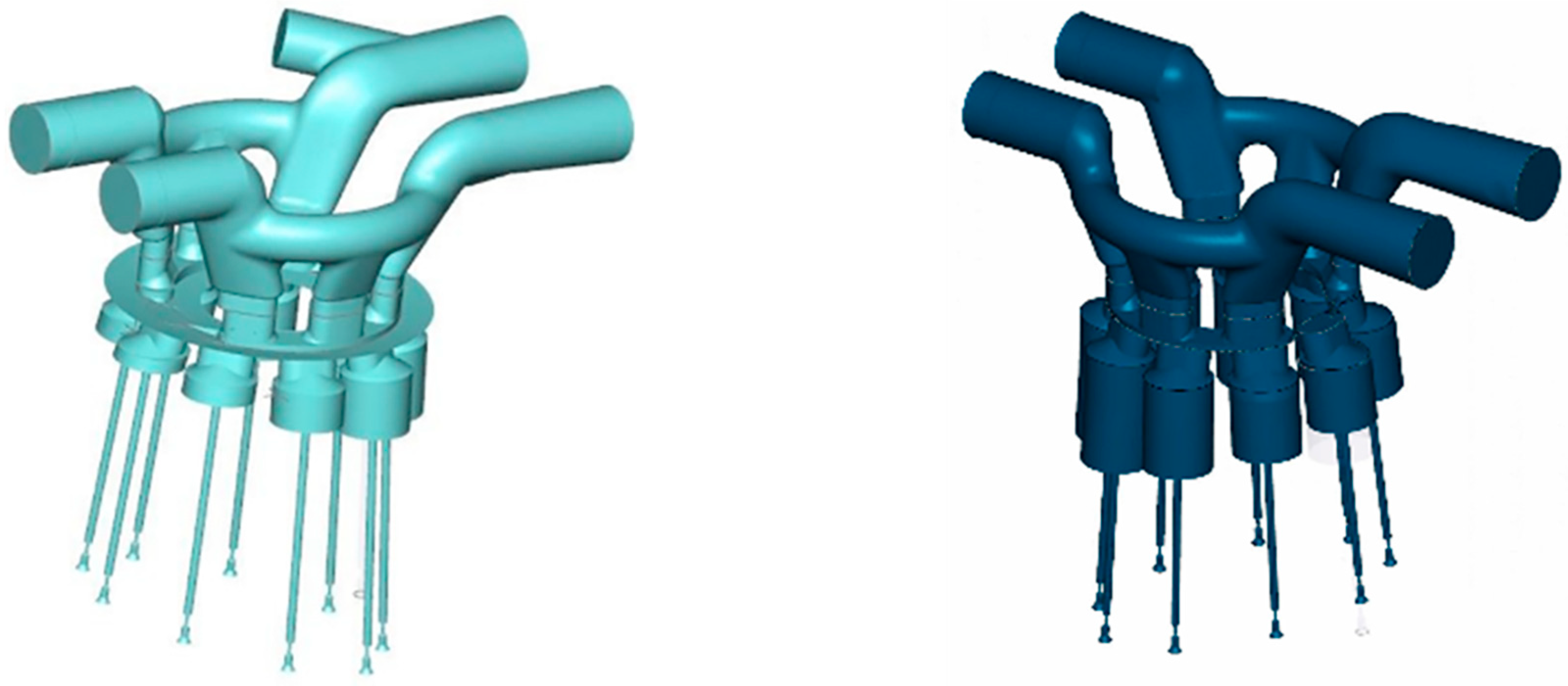
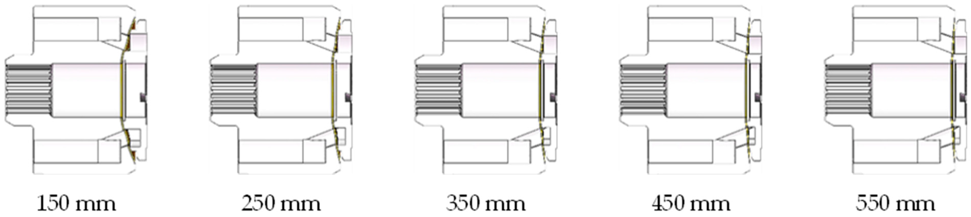
Based on the same original model, the rotor structure of the pump remains the same, and only the spherical radius parameters of the valve pair are changed. The original spherical radius of the plate is 300.6 mm. According to the original spherical radius size of the valve plate, it is divided into five groups of models, which are 150 mm, 250 mm, 350 mm, 450 mm, and 550 mm based on the increment of 100 mm as shown in Figure 11, with the minimum starting from 150 mm and the maximum being 550 mm.
Similarly, in order to compare the influence of different spherical radii on valve distribution characteristics, if the original parameters are maintained, the dividing circle of the valve plate and the top window of the nine pistons of the cylinder block will be different in the modeling process, so it is necessary to modify the dividing circle radius of the valve plate and keep it concentric. The modified parameters of each model are shown in Table 3. It can be seen that with the change in spherical radius, the spherical center distance of the valve plate changes.
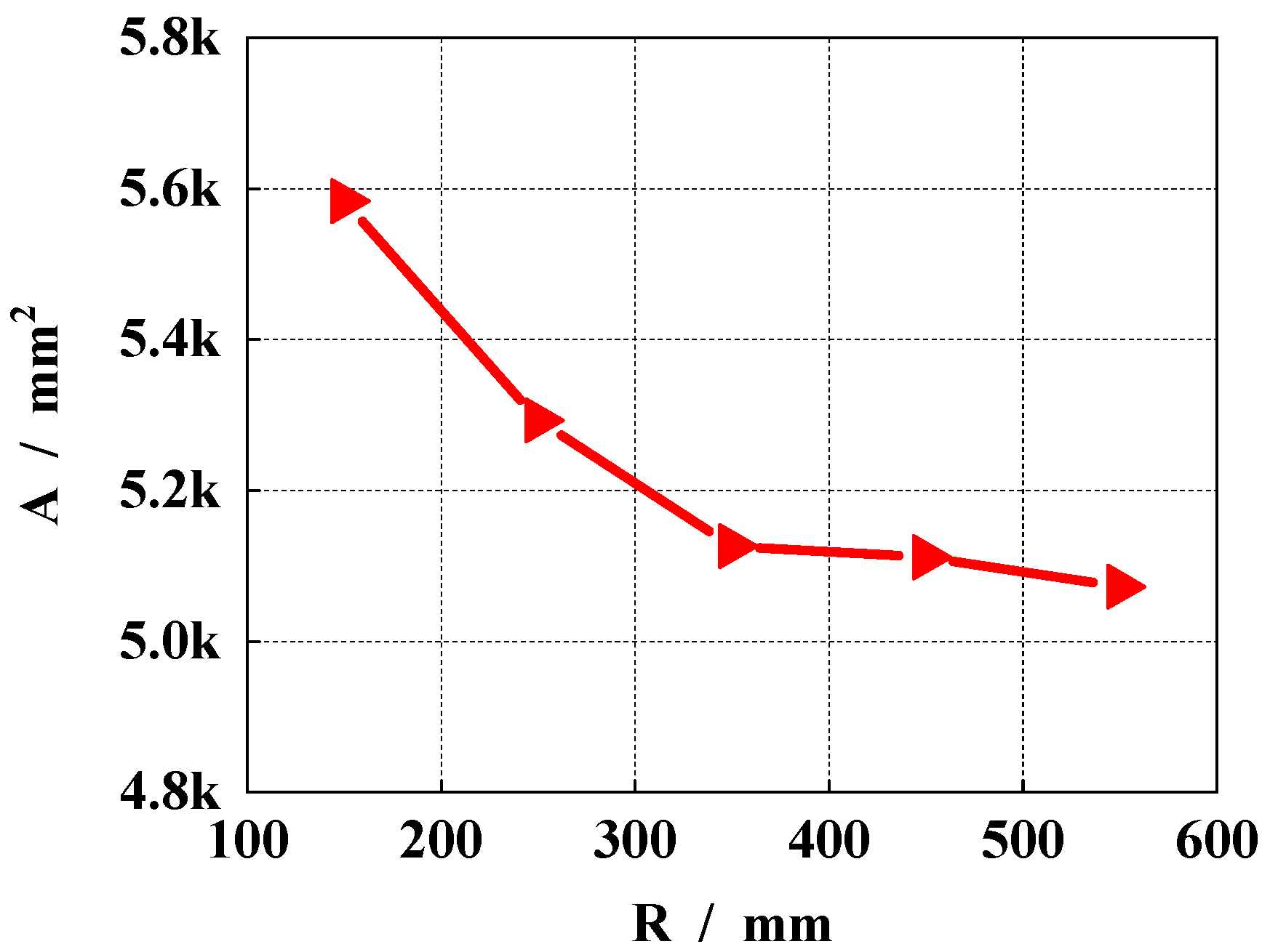
As the spherical radius increases, the bearing oil film is closer to the plane flow distribution. Therefore, in the modeling software, the contact area size of the bearing oil film is measured for further analysis.
As can be seen from Figure 12 and Table 4, with an increase in spherical radius, the bearing oil film area of the distribution gap gradually decreases. With an increase in the curvature of the oil film, the spherical radius is decreased, and the contact area is increased. Therefore, if the pressure difference in the distribution area is constant, the larger contact surface can improve the carrying capacity of the oil film.
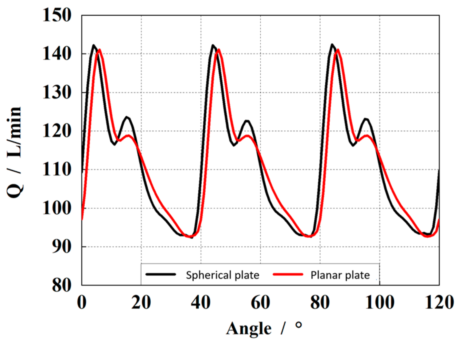
Figure 13 shows the influence of different spherical radii on the outlet flow pulsation. It can be seen that with an increase in the spherical radius, the outlet flow pulsation of the pump decreases first and then increases. According to the extracted data, when the radius of the sphere is 150 mm, the outlet flow pulsation rate is 45.02%. When the radius of the sphere is 250 mm, the outlet flow pulsation is 44.12%. When the radius of the sphere is 350 mm, the outlet flow pulsation is 42.05%. When the radius of the sphere is 450 mm, the outlet flow pulsation is 43.63%. When the radius of the sphere is 550 mm, the outlet flow pulsation is 48.35%, and the maximum and minimum flow pulsation difference is about 6.3%. According to the size of the flow pulsation rate, the optimal spherical radius is 350 mm.
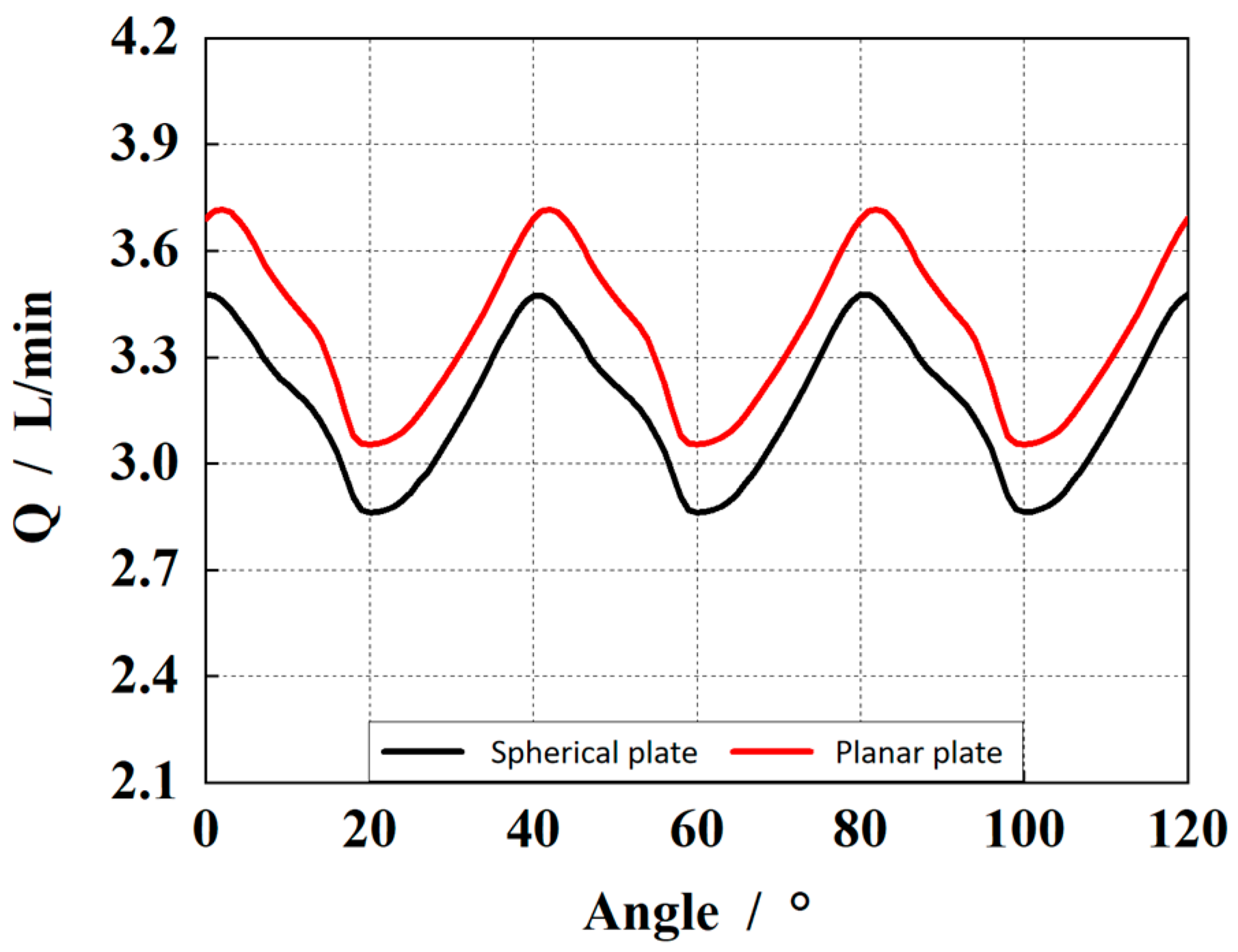
Figure 14 shows the influence of different spherical radii on the clearance leakage. As can be seen from the figure, with an increase in the spherical radius, the clearance leakage of the pump presents a changing trend of first decreasing and then increasing, which is consistent with the outlet flow pulsation rate. When the spherical radius is 350 mm, the clearance leakage is the smallest.
According to the extracted data, when the radius of the sphere is 150 mm, the gap leakage is 4.11 L/min. When the radius of the sphere is 250 mm, the gap leakage is 3.99 L/min. When the radius of the sphere is 350 mm, the gap leakage is 3.22 L/min. When the radius of the sphere is 450 mm, the gap leakage is 3.59 L/min. When the radius of the sphere is 550 mm, the gap leakage is 4.48 L/min, and the difference between the maximum and minimum leakage is about 1.26 L/min. According to the size of the leakage, the optimal spherical radius is 350 mm.
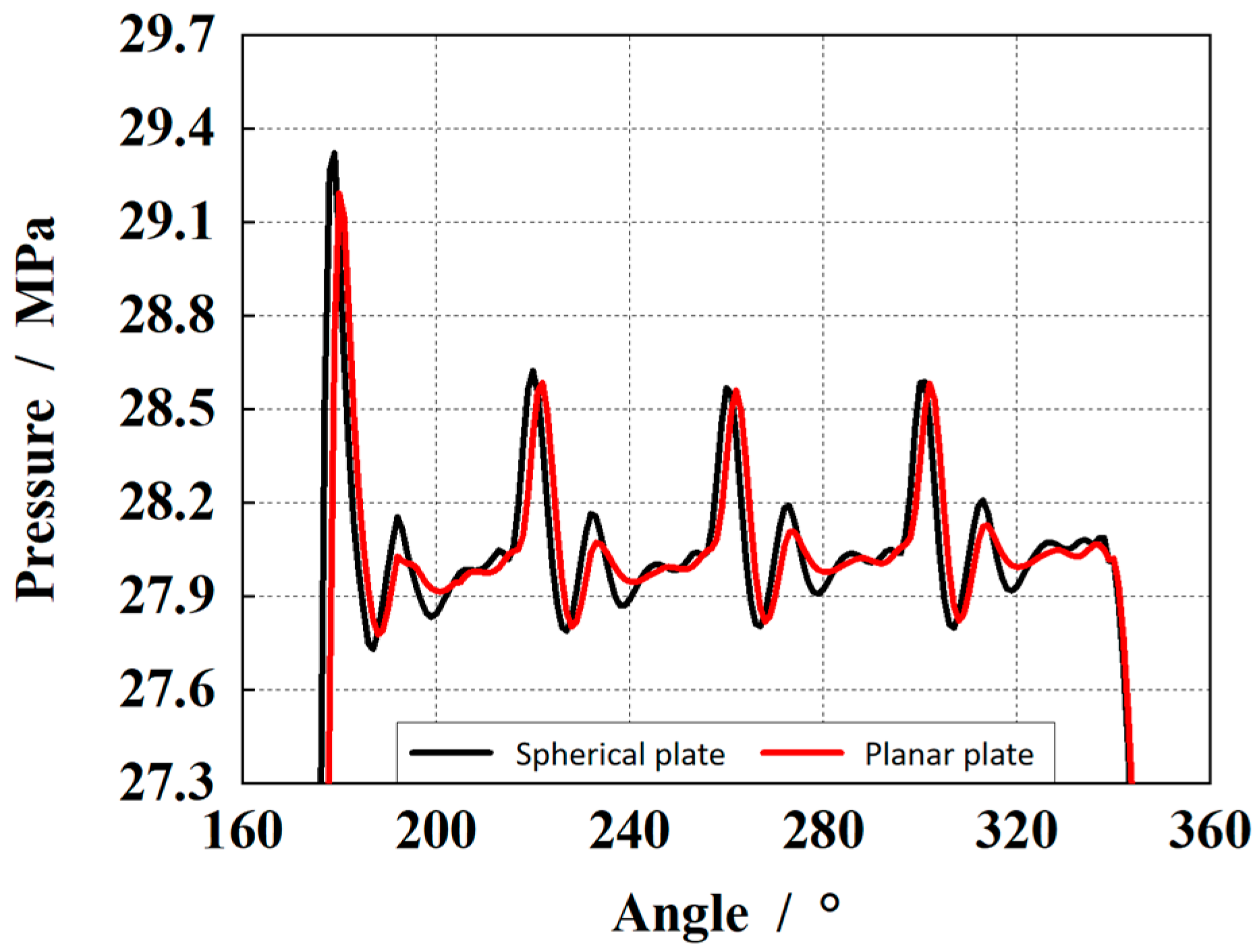
Figure 15 shows the influence of different spherical radii on pressure shock in the piston cylinder. It can be seen that with an increase in spherical radius, the pressure shock of different stages in the piston cavity changes differently. In general, the pressure shock at 350 mm is the smallest.
According to the extracted data, when the spherical radius is 150 mm, the maximum pressure impact in the cylinder is 29.39 MPa. When the radius of the sphere is 250 mm, the maximum pressure impact in the cylinder is 29.34 MPa; When the radius of the sphere is 350 mm, the maximum pressure impact in the cylinder is 29.25 Mpa. When the radius of the sphere is 450 mm, the maximum pressure impact in the cylinder is 29.27 Mpa. When the radius of the sphere is 550 mm, the maximum pressure impact in the cylinder is 29.29 MPa, and the difference between the maximum and minimum pressure impact is 0.14 MPa. According to the pressure impact size, the optimal spherical radius is 350 mm.
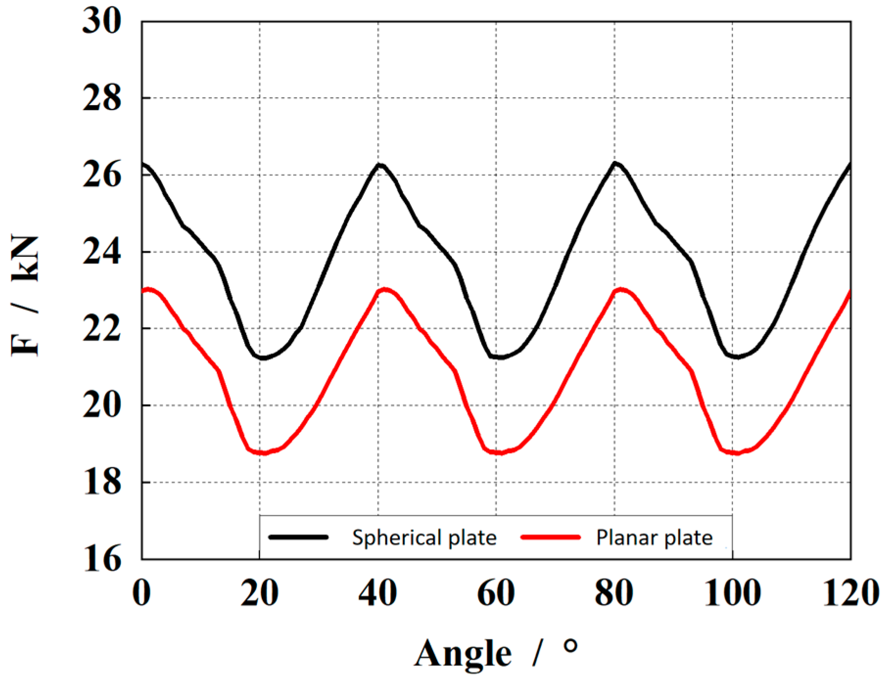
Figure 16 shows the influence of different spherical radii on the bearing capacity of the gap oil film, where the left one is the bearing capacity, and the right one is the average bearing capacity. As can be seen from the figure, the bearing capacity of the gap oil film shows a decreasing trend with an increase in the spherical radius. When the spherical radius is 150 mm, the bearing capacity of the oil film is the largest.
According to the extracted data, when the spherical radius is 150 mm, the bearing capacity of the gap oil film is 27.74 kN. When the spherical radius is 250 mm, the bearing capacity of the oil film is 24.85 kN. When the radius of the sphere is 350 mm, the bearing capacity of the oil film is 23.08 kN. When the radius of the sphere is 450 mm, the bearing capacity of the oil film is 22.55 kN. When the radius of the sphere is 550 mm, the bearing capacity of the gap oil film is 21.96 kN. According to the bearing size of the oil film, the optimal spherical radius is 150 mm.
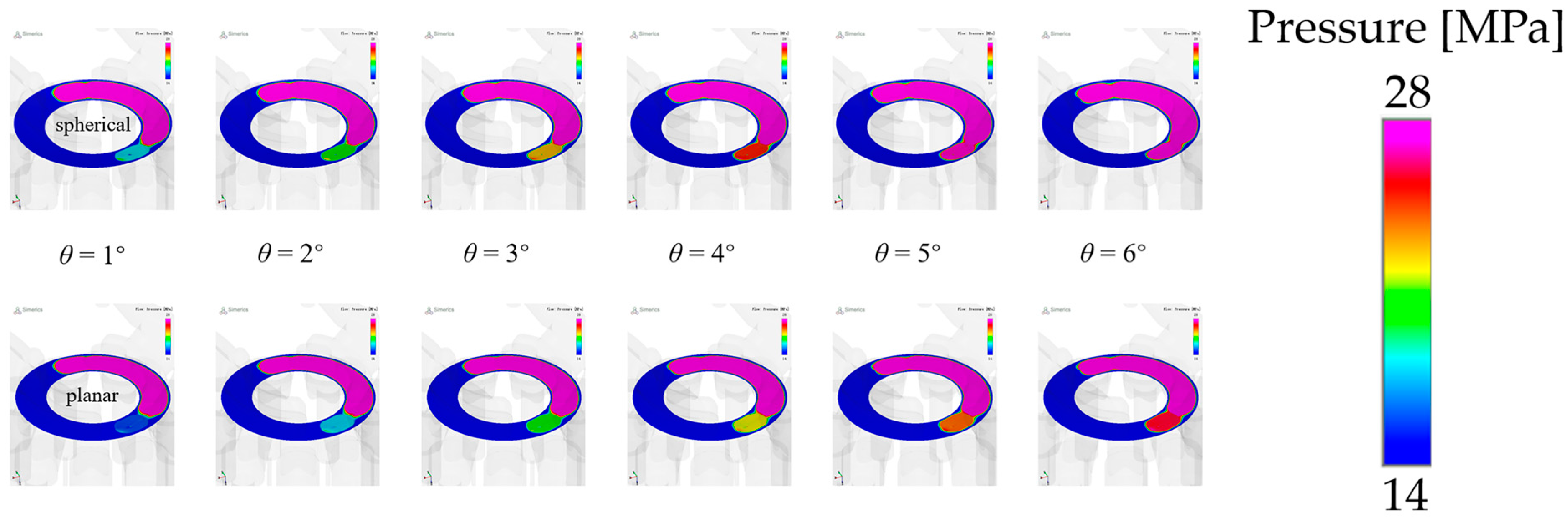
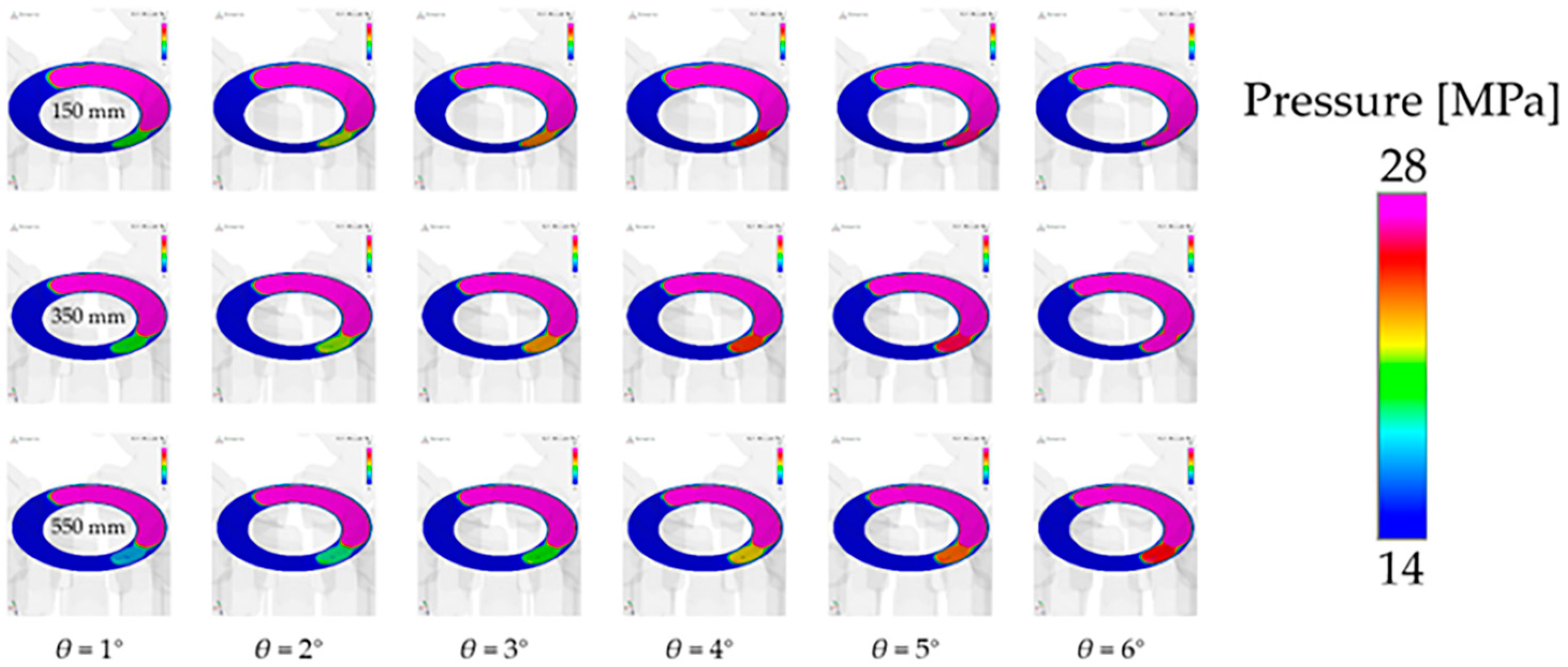
Figure 17 shows the gap oil film pressure distribution during the pre-boost process of the piston pump under different spherical radii (150 mm, 350 mm, and 550 mm; three groups). It can be seen from the figure that with the rotation of the cylinder block, the pre-boost speed of 150 mm and 300 mm is similar, and is faster than that of 550 mm. The pressure in the piston chamber rises faster, allowing the pre-boost process to be completed faster for the next stage of oil discharge.
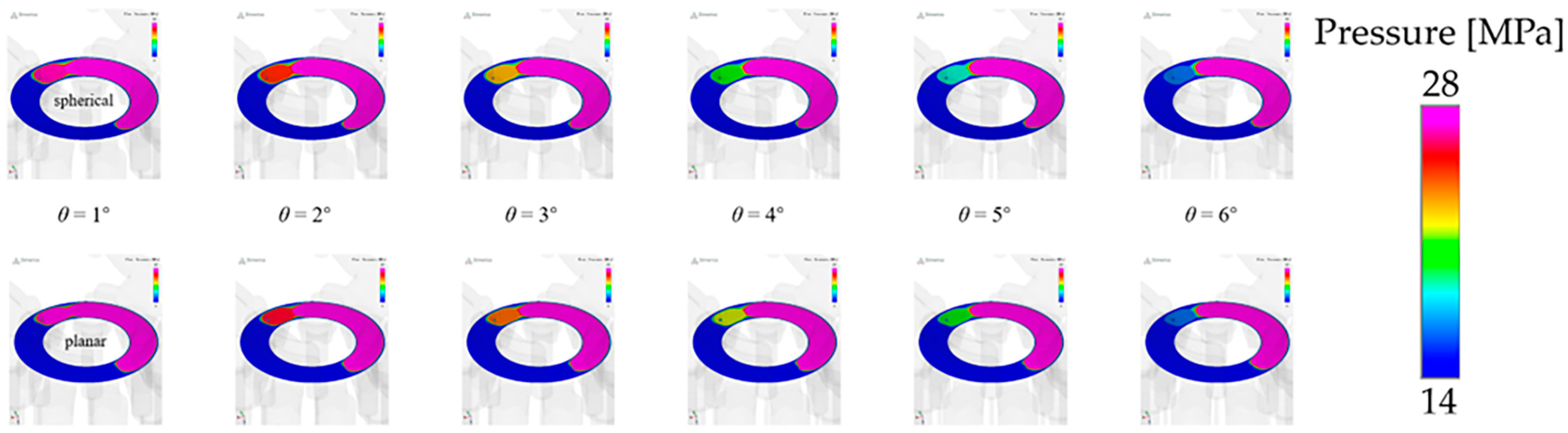
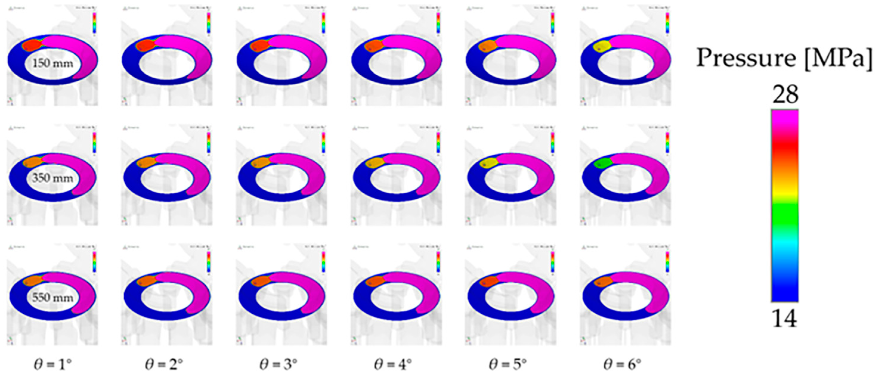
Figure 18 shows the gap oil film pressure distribution during the pre-pressure relief of the piston pump under different spherical radii (150 mm, 350 mm, and 550 mm; three groups). In order to better represent the pre-pressure relief effect, the pressure interval range under each cylinder block angle is independently set. The pressure range is 15 MPa~22 MPa when the cylinder block angle is 6°, and the pressure range is 10 MPa~12 MPa. It can be seen from the figure that with the rotation of the cylinder block, the pre-pressure relief speed of 350 mm is the fastest, the pre-pressure relief speed of 150 mm is the second fastest, and the pre-pressure relief speed of 550 mm is the slowest. With an increase in the pre-pressure relief speed, the pressure in the piston cavity can drop faster under the same cylinder block angle, which can complete the pre-pressure relief process faster and carry out the next stage of the oil absorption work.
Based on the above analysis, when the radius of the sphere is 350 mm, the output characteristics of the pump are optimal, and the distribution pair can maintain a good supporting role. When the radius of the sphere is greater than 350 mm, the bearing characteristics of the valve pair decrease, the leakage flow increases, and the pressure impact and flow pulsation are larger.

6. Conclusions

In this paper, the influence of the valve structure on the pressure-flow characteristics of the piston pump is studied. Based on the calculation and analysis of a variety of different valve structures, the following conclusions are drawn:
The spherical valve pair has significant advantages in pressure pulsation control and leakage control. Decreasing the curvature of the ball will increase the output pulsation of the piston pump. With a further increase in the curvature of the ball, the flow area of the oil film boundary will increase, resulting in an increase in leakage. On the other hand, with an increase in the curvature radius of the spherical valve pair, the supporting area of the oil film will continue to decrease, and the bearing capacity of the oil film weakens. Using the analysis of the simulation results, it is determined that the output characteristics are optimal when the radius of curvature is 350 mm.

Author Contributions

Conceptualization, S.X. and C.Z.; methodology, C.Z. and N.X.; software, C.Z. and N.X.; validation, S.X. and D.H.;formal analysis, B.Z.; investigation, B.Z.; resources, B.Z.; writing—original draft preparation, C.Z. and N.X.; writing—review and editing, S.X., D.H. and B.Z.; project administration, C.Z.; funding acquisition, G.G. All authors have read and agreed to the published version of the manuscript.

Funding

This research was funded by the Key technology of high pressure large displacement fast response closed piston pump, grant number 2023YFB3406700.

Data Availability Statement

Data are contained within the article.

Acknowledgments

The authors would like to thank the editors and the anonymous reviewers for their comments and suggestions.

Conflicts of Interest

Shunhai Xu is an employee of China Railway Engineering Equipment Group Co., Ltd., the authors declare no conflicts of interest.

References

  1. Bergada, J.M.; Kumar, S.; Davies, D.L.; Watton, J. A complete analysis of axial piston pump leakage and output flow ripples. Appl. Math. Model. 2012, 36, 1731–1751. [Google Scholar] [CrossRef]
  2. Chen, X.-F.; Gao, W.-K.; Zhang, J.-M. Analysis of Spherical Interstitial Flow Characteristics of Component in the Piston Pump. Chin. Hydraul. Pneum. 2021, 45, 87–97. [Google Scholar]
  3. Yang, G.-L.; Zhang, Z.-C. Analysis on Spherical Radius Optimum Value Range of Axial Piston Pump Port Plate. Hydraul. Pneum. Seals 2021, 41, 4. [Google Scholar]
  4. Zhang, X.; Xu, S.; Wang, S.; Geng, Y.; Shi, J.; Bai, L. Reliability Evaluation of Spherical Valve Pair in Axial Piston Pump. Mach. Tool Hydraul. 2023, 51, 183–191. [Google Scholar]
  5. Ye, S.; Lai, W.; Hou, L.; Bu, X. Modeling and Experimental Validation of Lubrication Characteristics of Spherical Valve-plate Pairs with Conical Cylinder Block. China Mech. Eng. 2022, 33, 2420–2428. [Google Scholar]
  6. Mandal, N.P.; Saha, R. Valve Plate Design of a Swash Plate Type Axial Piston Pump through Theoretical Simulation of Flow Dynamics. In Proceedings of the 7th International Fluid Power Conference, Aachen, Germany, 22–24 March 2010; pp. 1–12. [Google Scholar]
  7. Meng, G.-Y.; Shi, Y.-X.; Huang, J.-X.; Meng, H.; Sheng, K.-M. Effects of Spherical Port Plate on Performance of an Axial Piston Pump. Chin. Hydraul. Pneum. 2017, 1, 61–65. [Google Scholar]
  8. Pugi, L.; Alfatti, F.; Berzi, L.; Favilli, T.; Pierini, M.; Forrier, B.; D’Hondt, T.; Sarrazin, M. Fast modelling and identification of hydraulic brake plants for automotive applications. Int. J. Fluid Power 2020, 21, 169–210. [Google Scholar] [CrossRef]
  9. Zhanling, J. Research on thermal-fluid-structure coupling of valve plate pair in an axial piston pump with high pressure and high speed. Ind. Lubr. Tribol. 2018, 70, 1137–1144. [Google Scholar] [CrossRef]
  10. Wang, H.; Shi, G. Study of the slipper/swash plate pair loaded with a step motor-spring mechanism in the axial piston pump. Ind. Lubr. Tribol. 2022, 74, 706–713. [Google Scholar] [CrossRef]
  11. Zhao, B.; Guo, W.; Quan, L. Cavitation of a Submerged Jet at the Spherical Valve Plate/Cylinder Block Interface for Axial Piston Pump. Chin. J. Mech. Eng. 2020, 33, 197–211. [Google Scholar] [CrossRef]
  12. Du, B.; Jiang, J.; Li, G. Investigation of end effect in integrated permanent magnetic damper for cylinder block–valve plate pair in axial piston pump. AIP Adv. 2022, 12, 045004. [Google Scholar] [CrossRef]
  13. Wang, W. Analysis on the Side Leakage Amount of the Friction between Piston and Cylinder Block in Axial Piston Pump. Appl. Mech. Mater. 2014, 635, 341–345. [Google Scholar] [CrossRef]
  14. Quan, L.; Gao, H.; Guo, C.; Che, S. Assessment of the Dynamics Flow Field of Port Plate Pair of an Axial Piston Pump. Processes 2020, 8, 86. [Google Scholar] [CrossRef]
  15. Zhang, B.; Ma, J.; Hong, H.; Yang, H.; Fang, Y. Analysis of the flow dynamics characteristics of an axial piston pump based on the computational fluid dynamics method. Eng. Appl. Comput. Fluid Mech. 2016, 11, 86–95. [Google Scholar] [CrossRef]
Figure 1. Spherical distribution structure (left) and flat distribution structure (right).
Actuators 13 00147 g001
Figure 2. Schematic diagram of distribution plate.
Actuators 13 00147 g002
Figure 3. Schematic diagram of reactive force in the spherical valve train.
Actuators 13 00147 g003
Figure 4. Piston pump flow field model (Left) and mesh model (Right).
Actuators 13 00147 g004
Figure 5. Comparison of the outlet flow of the piston pump with spherical and planar structures.
Actuators 13 00147 g005
Figure 6. Comparison of clearance leakage of the piston pump with spherical and planar structures.
Actuators 13 00147 g006
Figure 7. Comparison of pressure impact in the piston cavity with the spherical and plane structure.
Actuators 13 00147 g007
Figure 8. Comparison of bearing capacity between the spherical structure and plane structure.
Actuators 13 00147 g008
Figure 9. Pressure distribution of the spherical structure and planar structure gap (pre-boost).
Actuators 13 00147 g009
Figure 10. Pressure distribution of the spherical structure and planar structure gap (pre-pressure relief).
Actuators 13 00147 g010
Figure 11. Structure models with different spherical radii.
Actuators 13 00147 g011
Figure 12. Size of bearing oil film area with different spherical radius.
Actuators 13 00147 g012
Figure 13. Comparison of outlet flow pulsation rates under different spherical radii.
Actuators 13 00147 g013
Figure 14. Comparison of pump clearance leakage under different spherical radii.
Actuators 13 00147 g014
Figure 15. Comparison of in-cylinder pressure impact sizes of pumps with different spherical radii.
Actuators 13 00147 g015
Figure 16. Comparison of bearing capacity of gap oil film under different spherical radii.
Actuators 13 00147 g016
Figure 17. Oil film pressure distribution at different spherical radii (pre-pressure boost).
Actuators 13 00147 g017
Figure 18. Oil film pressure distribution at different spherical radii (pre-pressure relief).
Actuators 13 00147 g018
Table 1. Grid parameters for various parts in the fluid domain.
Inlet and Suction PortDistribution PlatePiston Cavity
Maximum grid size0.010.0080.005
Minimum grid size0.0010.00040.0005
Surface grid size0.0050.0020.002
Total number of grids1,391,161
Total number of faces5,035,447
Total number of nodes2,012,674
Table 2. Simulation parameters of the model.
Value [Unit]
Piston diameter28 [mm]
Distribution circle diameter110.5 [mm]
Maximum swing angle of swashplate16.38°
Dead volume of cavity16,357.9 [mm3]
Film thickness25 [μm]
Rotational speed1500 [rpm]
Inlet pressure0.5 [MPa]
Outlet pressure28 [MPa]
Table 3. Modified size of valve plate and cylinder block with different spherical radii.
Spherical radius/mm150250350450550
Ball center distance/mm125.61231.89334.44435.83536.71
Dividing circle radius of plate/mm42.4641.4640.6240.3240.13
Table 4. Size of bearing oil film area with different spherical radii.
Spherical radius/mm150250350450550planar
Curvature/mm0.00670.00390.00290.00220.00180
Area size/mm25583.545292.885125.945111.395072.415026.55
Disclaimer/Publisher’s Note: The statements, opinions and data contained in all publications are solely those of the individual author(s) and contributor(s) and not of MDPI and/or the editor(s). MDPI and/or the editor(s) disclaim responsibility for any injury to people or property resulting from any ideas, methods, instructions or products referred to in the content.

