
Non-Electrically Driven Acoustic Actuator

Graduate School of Informatics and Engineering, University of Electro-Communications, 1-5-1, Chofugaoka, Chofu-shi 182-8585, Tokyo, Japan
*
Author to whom correspondence should be addressed.
Actuators 2024, 13(4), 148; https://doi.org/10.3390/act13040148
Submission received: 16 March 2024
/
Revised: 10 April 2024
/
Accepted: 10 April 2024
/
Published: 16 April 2024
(This article belongs to the Special Issue Actuators in 2024)
Abstract
:Nuclear power plants have high radiation levels and humans cannot work directly on them. Therefore, it is necessary to establish effective repair work methods. One promising approach is the use of disaster relief robots. However, strong radiation affects circuits and electronic devices. Because typical robots contain electrical circuits and are controlled by radio waves, they are difficult to use in highly radioactive environments. In this study, we propose a non-electrically driven acoustic actuator that does not use electronic circuits and is driven by sound waves. To realize this goal, we have investigated a sound wave drive using a cylindrical container.
1. Introduction
When repairing cracks in concrete buildings at nuclear power plants, it is extremely important to ensure safety. However, it is remarkably difficult to repair buildings under extremely high radiation conditions. Therefore, the development of a method for regularly repairing nuclear power plants is a pressing concern. The use of disaster relief robot technology is expected to be a powerful means of solving this problem [1,2,3,4]. Many studies of disaster robots have been carried out. These include research on small autonomous mobile robots intended for use in pipes [5] and on humanoid robots intended for use in power plants [6]. Although these robots are developed with various tasks in mind, virtually all disaster relief robots were equipped with electrical circuits and operate using electricity.
When a robot carries out work in a nuclear power plant, it is necessary to consider the effects of high radiation on the robot. Unfortunately, the radiation inside the nuclear power plant destroys electronic circuits and electric devices. Strong radiation creates strong electrical noise, interfering with radio signals. If a robot operates under strong radiation, its electrical circuits will be destroyed in a short period of time, making it difficult to operate for a long period of time [7]. For this reason, it is difficult to use conventional robots that use electricity in strong radiation environments.
When using conventional robots at nuclear power plants, there are also challenges regarding how to dispose of them after use. After robots used at nuclear power plants break down, they become scrap and must be removed. For instance, a TV broadcast in 2011 reported a situation in which a robot was left behind while investigating a nuclear reactor building [8].
In order to overcome this situation, research is actively being conducted on robots that are designed to work in nuclear power plants [9,10,11,12,13,14,15]. Some robot designs prevent radiation from affecting internal electronic circuits and critical components. Such robots use parts that are less susceptible to radiation. The effects of radiation are reduced by the use of wired rather than wireless communication with the robot. However, they are still a work in progress and many challenges remain.
Recently, other approaches have used physical phenomena other than electromagnetic force to drive robots. For example, many researchers are focusing on soft actuators and soft robots as a new approach to overcome the limitations of traditional robots [16,17,18]. Unlike robots made of metal, these robots are made of soft material and can change their shape freely due to their flexibility. Therefore, soft robots have various characteristics that are different from traditional robots. As an example, soft robots can deform themselves, allowing them to explore smaller areas than those permitted by their original bodies [19]. Because soft robots are soft, they are difficult to break even if they receive strong external shocks [20]. Pneumatic pressure is often used as a drive source for soft robots. McKibben actuators are an older example of pneumatic actuators and have been studied for a long time [21,22]. They are utilized in various robots such as infant robots [23], humanoid robots [24,25], quadruped robots [26], and worm-like robots [27] because they are safe. Many other soft robots using pneumatic actuators have been studied [28,29]. Some soft actuators are driven by hydraulics rather than pneumatics [30]. These soft actuators are soft themselves but require a pump to control the actuator pressure. Hence, the robot must be connected to the pump, making it difficult to control the robot remotely.
In addition to actuators that have been realized using air pressure, several studies of non-electric actuators have been reported. Some non-electrically driven actuators are stimulus-responsive actuators. They are sensitive to external environmental influences such as light [31], water [32], electric field [33], pH [34,35,36], and temperature [37,38]. However, because these actuators operate in response to environmental stimuli, there are limitations on the conditions under which they can be used. It is difficult to prepare the conditions necessary to drive actuators in the harsh environment of a nuclear power plant.
Considering these problems, it is desirable to be able to control a robot using a drive source other than electricity, one that is not affected by radiation when a robot is operated in a high-radiation environment such as a nuclear power plant.
In this paper, we aim to solve this problem by focusing on the movement of objects by sound. Sound waves are a physical phenomenon caused by vibrations in the air and do not, essentially, interfere with radiation, which is predominantly composed of electromagnetic waves. Since sound waves can be generated from a distance, it may be possible to carry out work using sound waves in areas where radiation levels are high and it is difficult or unsafe for people to enter. If a robot that can be moved by sound waves is created, it will be possible to remotely control the robot not only in environments filled with radiation, such as nuclear power plants, but also in spaces that radio waves cannot reach. Furthermore, if the robot can be operated from the outside using sound, there will be no need to mount an electronic board on the robot. Therefore, it is expected that it will be easier to create robots that use only materials that have lower environmental impacts than robots that use electricity.
We have previously studied the use of sound waves to drive objects, but at first we were only able to achieve movement on water [39]. Later, the actuator was successfully driven on the ground using Helmholtz resonance [40]. Although we succeeded in moving actuators on the water and the ground, it was difficult to control the direction of actuator movement. To solve the problems, in this paper, we designed another type of actuator using cylindrical vessels. We applied a ratchet mechanism to the cylindrical vessels and confirmed that different operations can be achieved by changing the frequency applied to the actuator.
The structure of this paper is as follows. Section 2 describes the design of the cylindrical vessel actuator. We also provide a theoretical analysis of the proposed actuator. We describe the experimental setup used to verify the features of the proposed actuator and demonstrate results regarding the actuator movements in Section 3. Section 4 contains the conclusion and our proposal regarding future work on the subject.
2. Design of Cylindrical Vessel Actuator
2.1. Outline of Cylindrical Actuator
Honkyu [41] showed that when a paper cup is exposed to a specific frequency, it moves depending on the frequency, and concluded that this phenomenon may be caused by resonance. Based on this feature, we theorized that it may be possible to achieve omni-directional movement by combining various types of cups. First, we measured the difference in the relationship between the frequency and the behavior of different types of cups. We conducted various experiments using different types of cups. During the experiment, cups showed various behaviors depending on the frequency of the sound waves, but the direction of movement was not stable and the reproducibility was low.
The various movements caused by the vibration of sound waves and the shape and friction of the cups led us to consider the possibility of controlling the movement caused by the vibration by designing an actuator. However, the cups were asymmetrical in shape, and their balance was poor when they were tilted sideways, making them unsuitable for the desired actuator design.
Therefore, we focused on a cylindrical container. This cylindrical container was vertically symmetrical. Therefore, it is easy to obtain good balance when it is tilted, making it easy to design an actuator. We also decided to use a ratchet mechanism as a method of controlling movement through vibration. A ratchet mechanism is used to limit movement in one direction. The ratchet mechanism used in this study is shown in Figure 1. As shown in Figure 1, the actuator is composed of the cylindrical container and legs. The legs are placed diagonally. By placing the legs diagonally, the frictional force changes depending on the movement of the actuator. As shown in Figure 2a, the friction force becomes strong when the actuator moves to the right. On the other hand, as shown in Figure 2b, the friction force becomes weak when the actuator moves to the left. As a result, the ratchet mechanism only enables the actuator to move to the left. This rachet mechanism is used in children’s toys, although manufacturers usually use an asymmetric-mass motor rather than soundwaves to drive the motion, e.g., in the Hexbug Nano series [42]. These toys are used not only for children to play with but also by physicists to demonstrate the physical model of active solids [43].
2.2. Cylindrical Actuator Design
The actual actuator designed in this study is shown in Figure 3. It consists of a cylindrical container with two rows of five legs attached at an angle to the floor. A more detailed schematic is shown in Figure 4. The side view in Figure 4 shows the mouth facing left, and the bottom view shows the mouth facing up.
The material of the cylindrical container used in this study was polyethylene. The container’s height was 10 cm, and its bottom diameter was 6 cm. The material of the ratchet foot was polyvinyl chloride, and the ratchet foot was 0.6 cm wide and 0.25 cm thick. The length of each foot was 2.7 cm for feet (4) and (7) and 3 cm for the other feet, as shown in the bottom view in Figure 3.
The resonance frequency f of the cylindrical container is provided by the following equation when the temperature is t, any odd number is n, the length of the cylindrical container is L, and the diameter of the mouth of the cylindrical container is d [44].
where c denotes the sound speed. c can be calculated as follows:
where R is the gas constant. γ represents the specific heat ratio. M represents the average molecular weight of gas. The specific heat ratio in air γ is approximately 1.403 when the gas constant R is 8.314462. M is about 28.966 × 10⁻³ [kg/mol]. Therefore, the resonance frequency f of the cylindrical vessel in this study can be obtained using Equations (1) and (2) as follows:
The room temperature was 11.9 °C on the day of the experiment. Therefore, using Equation (3), the resonance frequency of the cylindrical container in this study was determined to be 683 Hz when n = 1.
Next, the resonance frequency f of the foot was provided by the following equation using λn = nπ/L, where Young’s modulus is E, the sectional secondary moment is I, the density is ρ, the cross-sectional area is A, any integer greater than 1 is n, and the foot length is L [45,46,47].
Since the foot is rectangular, if the width of the foot is b and the thickness of the foot is h, the cross-sectional secondary moment I is calculated using the following equation.
As shown above, the material of the foot, which is the ratchet mechanism used in this study, was polyvinyl chloride, with a width of 0.6 cm and a thickness of 0.25 cm. The lengths of feet (4) and (7) were 2.7 cm, and the lengths of the other feet were 3 cm. Therefore, the cross-sectional secondary moment was 7.8125 × 10⁻¹⁵ m4. The Young’s modulus of polyvinyl chloride is 0.2~0.8 GPa, and the measured density is 1.33 g/cm3.
Therefore, using Equations (4) and (5), we can conclude the average resonance frequency of the long leg was 73.2 Hz at n = 1, 292.7 Hz at n = 2, 658.6 Hz at n = 3, and 1170.8 Hz at n = 4, and that of the short leg was 90.3 Hz at n = 1, 361.4 Hz at n = 2, 813.1 Hz at n = 3, and 1445.5 Hz at n = 4.
3. Experiments with Cylindrical Vessel Actuator
3.1. Comparison Experiment Regarding Actuator Leg Length
In this research, we aimed to control a robot’s movement using different frequencies. To achieve this goal, we considered using the difference in frictional force from the left and right sides caused by the difference in leg length of the actuator. In our scenario, the presence or absence of foot contact was controlled by the difference in vibration of the foot due to the difference in the frequency of the sound waves. In order to achieve this goal, it was necessary to confirm whether the vibrations of the robot’s legs could be properly controlled using different frequencies. The resonance frequency of plastic has a certain range, and it is difficult to uniquely determine the resonance frequency theoretically. Therefore, we conducted preliminary experiments concerning how to arrange long legs and short legs on the robot. We developed eight prototypes to determine the optimal layout and length of the actuator legs to be used on the final prototype.
Figure 5 shows the specification of prepared prototypes. In the experiment, we used cylinders of the same size and changed the length and number of the legs. Based on the calculation results of the resonance frequency of the cylinder, we observed the movement of the actuator by changing the frequency applied to the actuator from 200 Hz to 800 Hz in 100 Hz increments.
In Prototype 0, it was not possible to control the robot’s movements. Since the prototypes were created manually, the length of the legs was slightly different. Therefore, the robot’s movement was unstable. Although Prototypes 1 and 2 moved forward at a specific frequency, they did not rotate. On the other hand, although Prototype 3 rotated at a specific frequency, it did not move forward. Prototype 4 moved forward but did not rotate. Prototypes 5 and 6 did not function well.
We were able to observe that the robot’s movement became slower even if the number of legs was decreased or increased from 10. Furthermore, the robot tended to rotate when the width of the legs was widened laterally. This was because the short legs no longer touched the floor when the width of the feet was widened. The robot tended to move more easily when the legs were slightly wider in a vertical direction.
Based on these experiments, we finally created Prototype 7. In Prototype 7, the robot’s forward movement and rotation could be controlled by differences in the frequency of sound waves in the experiments. Based on these experiments, we decided to conduct more detailed experiments using Prototype 7.
3.2. Cylindrical Actuator Movement Experiment
As in the case of the cup actuator, we applied sounds ranging from 200 Hz to 1200 Hz to the actuator while rotating it through 90°, as shown in Figure 6, and observed how it behaved. The actuators were placed approximately 30 cm away from the speaker. To facilitate measurement of the direction of movement, letters A, B, C, and D were assigned to the top, bottom, left, and right of the board on which the actuator was placed, as shown in the figure. To facilitate explanation, we also labeled (as Cases 1 to 4, respectively) whether the robot direction was set to A, B, C or D, as shown in Figure 6.
3.3. Movement Experimental Results
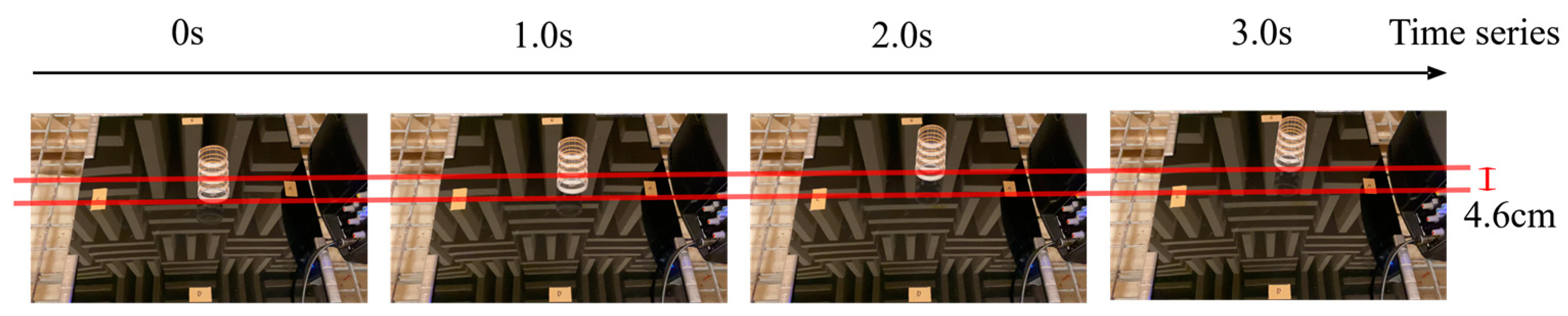
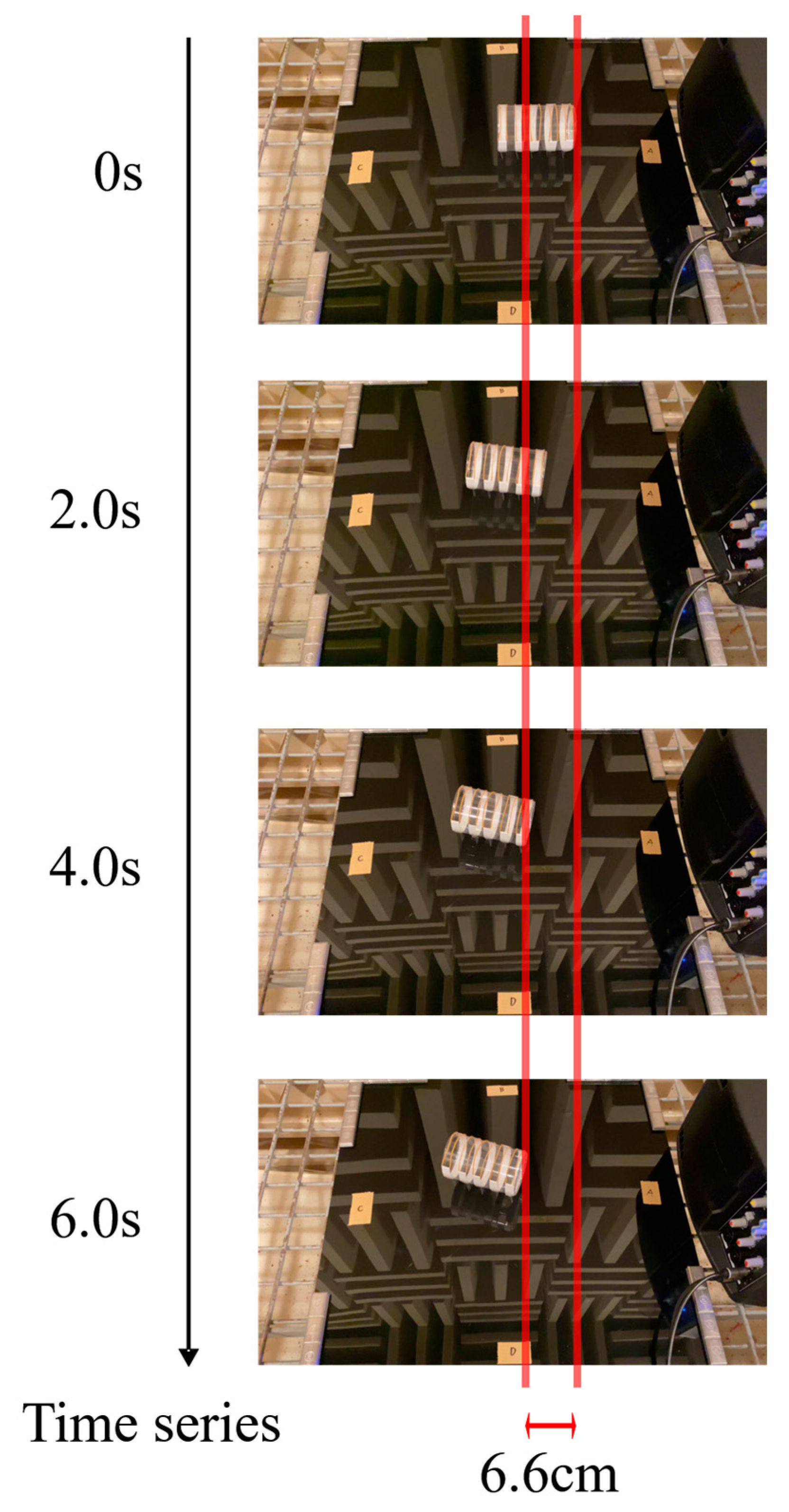
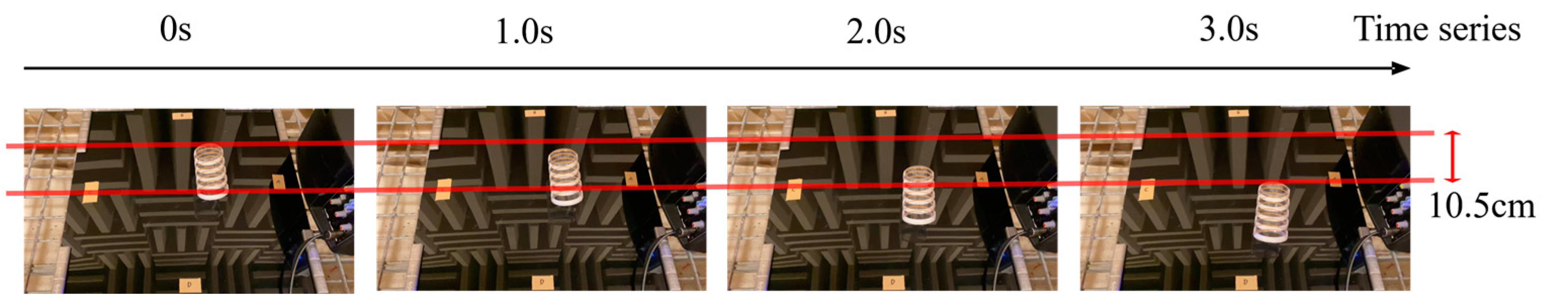
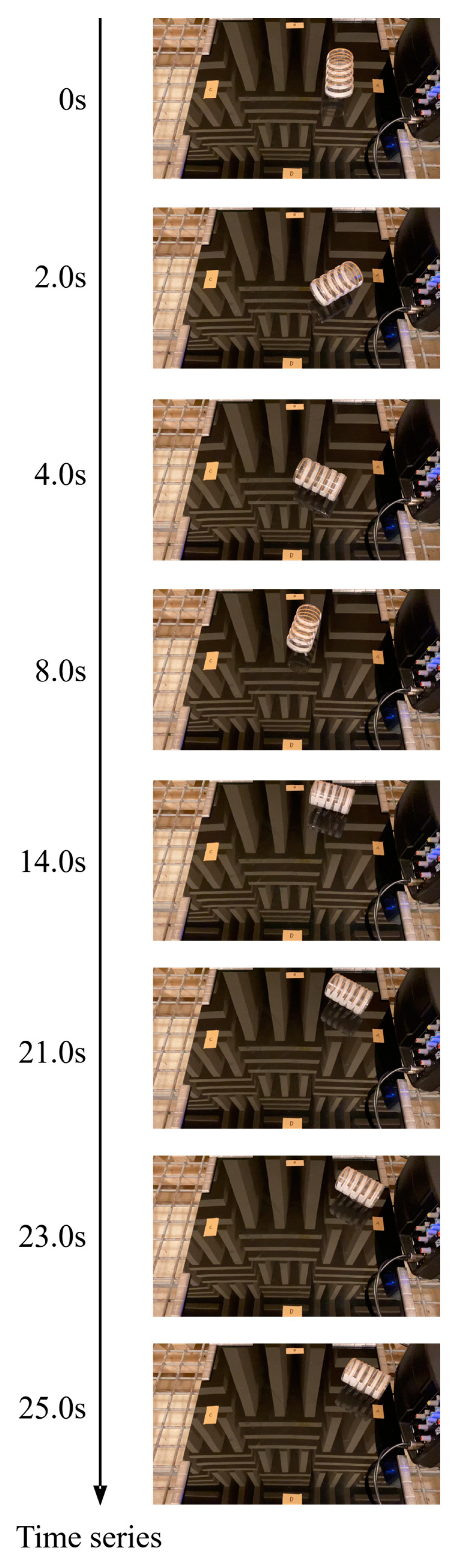
According to the experimental results, we confirmed that the developed actuator rotated at 200 Hz and moved forward at 800 Hz in Case 1 to Case 4. We show some examples of the robot’s movement in detail. Figure 7 and Figure 8 show the robot’s movement when its direction was set to direction A. Figure 7 shows the robot’s movement when the frequency of the generated sound was 200 Hz. Figure 8 shows the robot’s movement when the frequency of the generated sound was 800 Hz. Figure 9, Figure 10 and Figure 11 show the robot’s movement when its direction was set to direction B, direction C, and direction D, respectively. In Figure 9, Figure 10 and Figure 11, we show the robot’s movement when the frequency of the generated sound was 800 Hz. In all cases, the robot moved forward as we expected.
We also measured the movement speeds at 800 Hz in Cases 1 to 4. The movement speed of Case 1, Case 2, Case 3, and Case 4 was approximately 5.8 cm/s, 1.5 cm/s, 1.1 cm/s, and 3.5 cm/s, respectively. In all cases, the robots moved in the direction their mouths were facing.
3.4. Summary and Discussion of Cylindrical Actuator
In summary, the cylindrical actuator was able to rotate at 200 Hz and move forward at 800 Hz using a ratchet structure. This result may be due to the difference in resonance frequency between the cylindrical container and the legs.
The resonance frequency of the cylindrical container was 683 Hz, that of the long leg was 292.7 Hz and 658.6 Hz, and that of the short legs was 361.4 Hz and 813.1 Hz. This suggests that only the feet resonate at 200 Hz, but both the cylindrical container and the feet resonate at 800 Hz. Here, the resonance frequency of the foot is the average of the frequencies calculated using the Young’s modulus of polyvinyl chloride (0.2–0.8 GPa). Specifically, when Young’s modulus is 0.2 GPa, the resonance frequency of the long leg is 195.1–390.3 Hz for n = 2 and 439.1–878.1 Hz for n = 3. The resonance frequency of the short leg is 240.9–481.8 Hz for n = 2 and 542.0–1084.1 Hz for n = 3. From this, the experimentally determined resonance frequency of 200 Hz is included in the n = 2 range for the long leg, and 800 Hz is included in the n = 3 range for both the long and short legs.
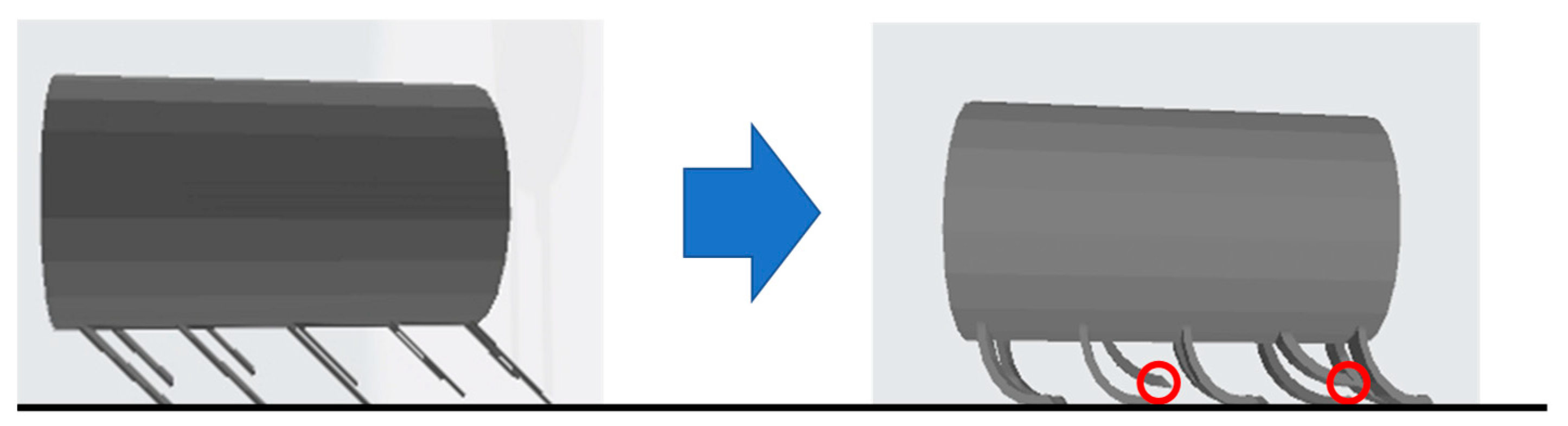
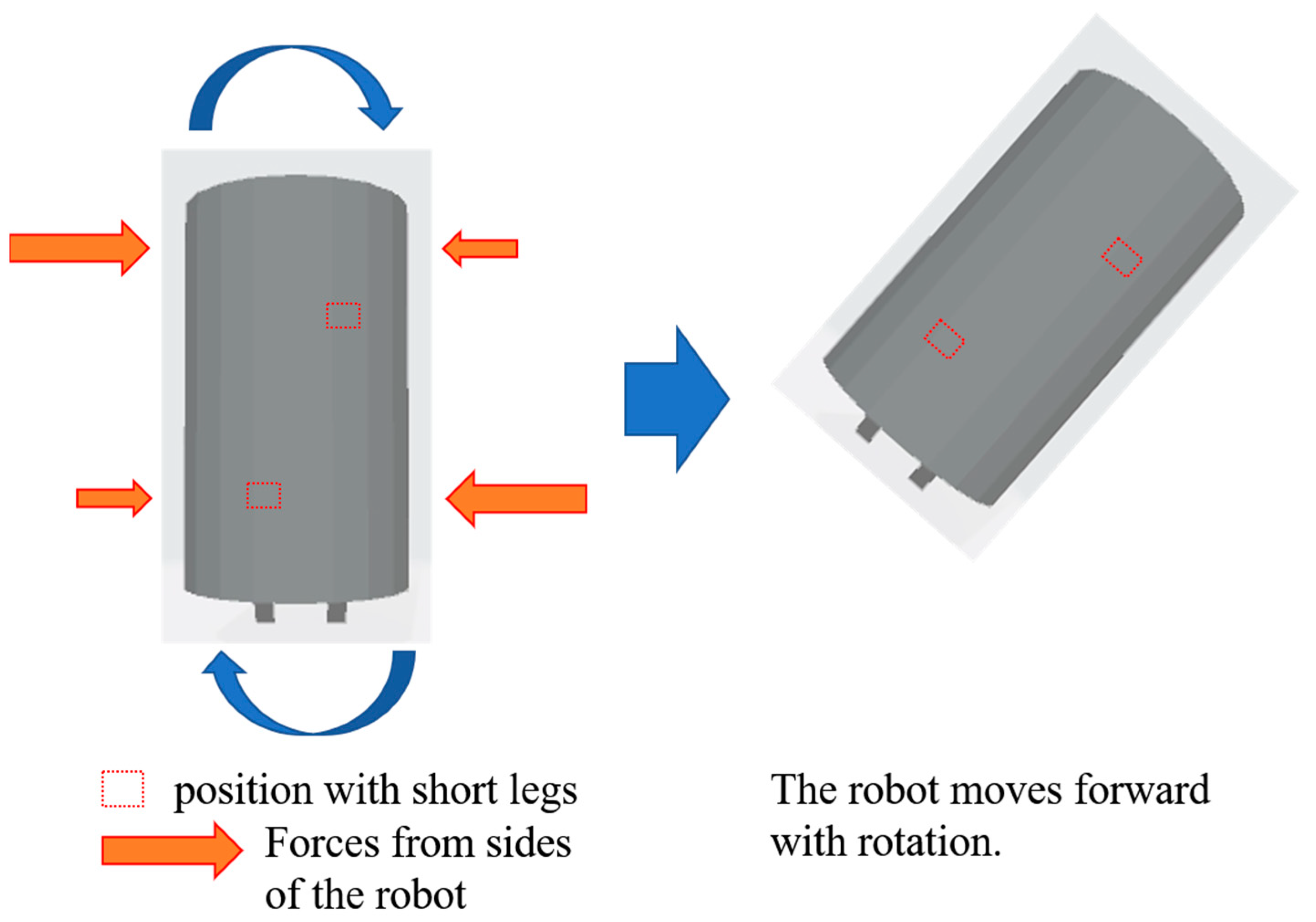
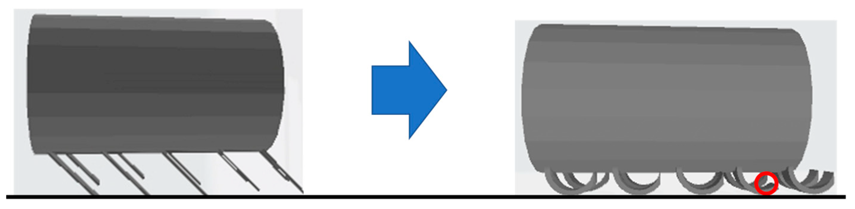
When the 200 Hz sound was applied to the robot, the long leg vibrated and the foot bent as shown in Figure 12. However, the short leg still did not touch the ground because the vibration was relatively weak. Therefore, the forces acting on the actuator from the left and right sides were uneven, as shown in Figure 13, resulting in a clockwise rotation.
When a sound of 800 Hz was applied, the foot and the cylindrical container vibrated, and the foot bent as shown in Figure 14. At 800 Hz, the vibration was stronger than at 200 Hz because the cylindrical container resonated in addition to the legs, which caused the short legs to move forward. Therefore, the forces acting on the actuator from the left and right sides were balanced, as shown in Figure 15, and as a result, the actuator moved only forward.
We also experimented with the possibility of omni-directional movement by combining rotation at 200 Hz and straight-line movement at 800 Hz. As a result of the experiment, the robot was able to move toward position A, but it was unable to move toward other positions. Figure 16 shows the movement from position (4) to position A in Figure 4.
The robot could not move because it had moved to a position where it was difficult for the sound from the speaker to reach it due to the large rotation when the 200 Hz sound was applied. In addition, the 800 Hz vibration was not transmitted, causing the robot to stop moving straight ahead. The robot was able to move to position A because the propulsive force of the 800 Hz sound was the strongest when it was directed toward A.
The movement to A was possible because the thrust was greatest when the 800 Hz sound was directed at A. Possible ways to improve the situation include changing the speaker to one with a higher output or a larger width, or using a more directional speaker.
4. Discussion and Conclusions
This study aimed to create a non-electrically driven acoustic actuator that could be operated in a nuclear power plant. To create the actuator, movement experiments were conducted with a cylindrical-container-based actuator.
After modification, the Helmholtz resonance actuator that we created was able to move in one direction, but it was difficult for us to move it in all directions due to structural and control problems. On the other hand, with the actuator using a cylindrical container, we were able to control rotational and linear motion depending on the frequency. However, omni-directional movement combining rotation and linear motion was difficult to achieve except in specific situations, because the rotation caused the speaker to move to a position where sound could not be transmitted.
In practical terms, it is assumed that various sizes of actuators will be used. According to the theoretical analysis described in this paper, the resonance frequency of the cylinder depends on the length of the cylinder. When the length of the cylinder is long, the cylinder resonates at a lower frequency. As a result of experiments, we determined that when the frequency is very low, not only the actuator but the entire floor vibrates. Hence, the experiment did not work very well. Additionally, as the size of the actuator increases, the weight of the actuator also increases, which requires more energy to move it. On the other hand, as the size of the actuator decreases, the resonance frequency increases accordingly. When the size decreases, the change in resonance frequency with respect to the change in size increases. Hence, it seems that if the actuator is small, it will be more difficult to determine the resonance frequency to operate it. As the actuator becomes smaller, it also becomes more susceptible to wind and other factors. From these points of view, there are certain limits to the size of robots that can be implemented using the proposed method. In future research, we would like to investigate to what extent this method can be used even if the actuator size is changed.
The development of sound-driven robots is still in its early stages. Robots that move using acoustic signals can do fewer things than electrically driven robots. Therefore, there are still issues that must be resolved before these robots can be used in practice.
We are considering developing a self-destructive robot for the application of sound-driven robots. In this scenario, the robot would be constructed of materials that break down in response to external stimuli (e.g., temperature) and contains repair materials. When in use, the robot is moved to the repair area using an acoustic signal and then self-destructed at that location using an external stimulus. Cracks in the wall would be filled by the repair material released in the self-destruction. To achieve this goal, we would like to construct robots made of temperature-sensitive materials and investigate whether they could self-destruct in hypothetical situations.
We also need to improve the robot’s movements so that it can be controlled more precisely. We have tried many designs and experimented with the best design currently available, but it is likely that a better design remains possible. Potential improvements include using a speaker with a higher output, wider width, and more directional characteristics to ensure stable sound transmission to the actuator.
Author Contributions
Conceptualization, T.N. and M.M.; methodology, T.N.; validation, T.N.; investigation, T.N. and M.M.; writing—original draft preparation, T.N.; writing—review and editing, M.M.; supervision, M.M.; project administration, M.M.; funding acquisition, M.M. All authors have read and agreed to the published version of the manuscript.
Funding
This research was supported by JSPS KAKENHI Grant Number JP20H02412.
Data Availability Statement
Data are contained within the article.
Conflicts of Interest
The authors declare no conflicts of interest.
References
- Gregory, J. Application of Multi-Robot Systems to Disaster-Relief Scenarios with Limited Communication. In Field and Service Robotics; Springer: Berlin/Heidelberg, Germany, 2016; Volume 113, pp. 639–653. [Google Scholar]
- Kamegawa, T.; Akiyama, T.; Sakai, S.; Fujii, K.; Une, K.; Ou, E.; Matsumura, Y.; Kishutani, T.; Nose, E.; Yoshizaki, Y.; et al. Development of a separable search-and-rescue robot composed of a mobile robot and a snake robot. Adv. Robot. 2020, 34, 132–139. [Google Scholar] [CrossRef]
- Deng, W.; Huang, K.; Chen, X.; Zhou, Z.; Shi, C.; Guo, R.; Zhang, H. Semantic RGB-D SLAM for Rescue Robot Navigation. IEEE Access 2020, 8, 221320–221329. [Google Scholar] [CrossRef]
- Ingale, K.; Deshmukh, A.; Deshpande, A.; Deshmukh, S.; Deshmukh, M.; Bhise, S. Multi-Agent Swarm Robotics for Accurate Position Detection in Disaster Scenarios. In Proceedings of the 2023 International Conference on Inventive Computation Technologies (ICICT), Lalitpur, Nepal, 26–28 April 2023; pp. 1454–1460. [Google Scholar]
- Shibata, T.; Sasaya, T.; Kawahara, N. Development of In-Pipe Microrobot Using Microwave Energy Transmission. J. Inst. Electron. Inf. Commun. Eng. B 2000, J83-B, 704–710. [Google Scholar] [CrossRef]
- Kawauchi, N.; Shiotani, S.; Kanazawa, H.; Sasaki, T.; Tsuji, H. A plant maintenance humanoid robot system. In Proceedings of the IEEE International Conference on Robotics and Automation, Taipei, Taiwan, 14–19 September 2003; pp. 2973–2978. [Google Scholar]
- Takakura, K. Protecting robot workers from radiation. Impact 2020, 10, 52–53. [Google Scholar] [CrossRef]
- ANNnewsCH. [Nuclear Power] Domestic Robot Left Behind in Reactor Building (11/10/21). Available online: https://www.youtube.com/watch?v=9AV4i6-2Q4s (accessed on 14 March 2022).
- Huruta, T.; Yoshida, T.; Nishimura, T.; Yamato, H. Development of the Exploring Robot toward Future Indoor Surveillance Missions in the Fukushima Daiichi Nuclear Power Plant. J. Robot. Soc. Jpn. 2014, 32, 92–97. [Google Scholar]
- Onishi, K.; Onishi, N.; Fujita, J.; Hara, K.; Hashimoto, T. Design and Development of Robots which Support Activities of Recovery from Nuclear Hazards. J. Robot. Soc. Jpn. 2014, 32, 816–824. [Google Scholar] [CrossRef]
- Nagatani, K.; Kiribayashi, S.; Okada, Y.; Otake, K.; Yoshida, K.; Tadokoro, S.; Nishimura, T.; Yoshida, T.; Koyanag, E.; Fukushima, M.; et al. Emergency response to the nuclear accident at the Fukushima Daiichi Nuclear Power Plants using mobile rescue robots. J. Field Robot. 2013, 30, 44–63. [Google Scholar] [CrossRef]
- Tsiligiannis, G.; Touboul, A.; Bricas, G.; Maraine, T.; Boch, J.; Wrobel, F.; Michez, A.; Saigne, F.; Godot, A.; Etile, A.; et al. Evaluation and Analysis of Technologies for Robotic Platforms for the Nuclear Decommissioning. In Proceedings of the 15th International Conference on Design and Technology of Integrated Systems in Nanoscale Era, Marrakech, Morocco, 1–3 April 2020. [Google Scholar]
- Han, Z.; Duan, X.; Wang, Y.; Pan, Y.; Wu, Y. Robot System and Fastening Force Control for Sealing Blocking Plates of Steam Generator. In Proceedings of the 9th IEEE International Conference on CYBER Technology in Automation, Control, and Intelligent Systems, Suzhou China, 29 July–2 August 2019. [Google Scholar]
- Nagatani, K.; Kiribayashi, S.; Okada, Y.; Tadokoro, S.; Nishimura, T.; Yoshida, T.; Koyanagi, E.; Hada, Y. Redesign of rescue mobile robot Quince. In Proceedings of the 2011 IEEE International Symposium on Safety, Security and Rescue Robotics, Kyoto Japan, 1–5 November 2011. [Google Scholar]
- Dong, P.; Wang, X.; Xing, H.; Liu, Y.; Zhang, M. Design and control of a tracked robot for search and rescue in nuclear power plant. In Proceedings of the 2016 International Conference on Advanced Robotics and Mechatronics, Macau, China, 18–20 August 2016. [Google Scholar]
- Zolfagharian, A.; Durran, L.; Gharaie, S.; Rolfe, B.; Kaynak, A.; Bodaghi, M. 4D printing soft robots guided by machine learning and finite element models. Sens. Actuators A Phys. 2021, 328, 112774. [Google Scholar] [CrossRef]
- Sachin; Wang, Z.; Hirai, S. Analytical Modeling of a Soft Pneu-Net Actuator Subjected to Planar Tip Contact. IEEE Trans. Robot. 2022, 38, 2720–2733. [Google Scholar] [CrossRef]
- Zolfagharian, A.; Parvez Mahmud, M.A.; Gharaie, S.; Bodaghi, M.; Kouzani, A.Z.; Kaynak, A. 3D/4D-printed bending-type soft pneumatic actuators: Fabrication, modelling, and control. Virtual Phys. Prototyp. 2020, 15, 373–402. [Google Scholar] [CrossRef]
- Hawkes, E.W.; Blumenschein, L.H.; Greer, J.D.; Okamura, A.M. A soft robot that navigates its environment through growth. Sci. Robot. 2017, 2, 101. [Google Scholar] [CrossRef] [PubMed]
- Nishikawa, Y.; Matsumoto, M. Lightweight indestructible soft robot. IEEE Trans. Electr. Electron. Eng. 2018, 13, 652–653. [Google Scholar] [CrossRef]
- Tondu, B.; Lopez, P. Modeling and control of McKibben artificial muscle robot actuators. IEEE Control Syst. 2000, 20, 15–38. [Google Scholar] [CrossRef]
- Tondu, B. Modelling of the McKibben artificial muscle: A review. J. Intell. Mater. Syst. Struct. 2012, 23, 225–253. [Google Scholar] [CrossRef]
- Norioka, K.; Hosoda, K. Motor Development of an Pneumatic Musculoskeletal Infant Robot. In Proceedings of the IEEE International Conference on Robotics and Automation, Shanghai, China, 9–13 May 2011; pp. 963–968. [Google Scholar] [CrossRef]
- Niiyama, R.; Nagakubo, A.; Kuniyoshi, Y.; Mowgli, A. Bipedal Jumping and Landing Robot with an Artificial Musculoskeletal System. In Proceedings of the IEEE/RSJ International Conference on Intelligent Robots and Systems, Rome, Italy, 10–14 April 2007; pp. 2546–2551. [Google Scholar] [CrossRef]
- Niiyama, R.; Nishikawa, S.; Kuniyoshi, Y. Athlete Robot with Applied Human Muscle Activation Patterns for Bipedal Running. In Proceedings of the IEEE-RAS International Conference on Humanoid Robots, Nashville, TN, USA, 6–8 December 2010; pp. 498–503. [Google Scholar] [CrossRef]
- Rosendo, A.; Nakatsu, S.; Narioka, K.; Hosoda, K. Pneupard: A biomimetic musculoskeletal approach for a feline-inspired quadruped robot. In Proceedings of the IEEE/RSJ International Conference on Intelligent Robots and Systems, Tokyo, Japan, 3–7 November 2013; pp. 1452–1457. [Google Scholar] [CrossRef]
- Boxerbaum, A.; Chiel, H.J.; Quinn, R.D. A New Theory and Methods for Creating Peristaltic Motion in a Robotic Platform. In Proceedings of the IEEE International Conference on Robotics and Automation, Anchorage, AK, USA, 3–7 May 2010; pp. 1221–1227. [Google Scholar] [CrossRef]
- Steltz, E.; Mozeika, A.; Rodenberg, N.; Brown, E.; Jaeger, H.M. JSEL: Jamming Skin Enabled Locomotion. In Proceedings of the IEEE/RSJ International Conference on Intelligent Robots and Systems, St. Louis, MO, USA, 10–15 October 2009; pp. 5672–5677. [Google Scholar] [CrossRef]
- Shepherd, R.F.; Ilievski, F.; Choi, W.; Morin, S.A.; Stokes, A.A.; Mazzeo, A.D.; Chen, X.; Wang, M.; Whitesides, G.M. Multigait soft robot. Proc. Natl. Acad. Sci. USA 2011, 108, 20400–20403. [Google Scholar] [CrossRef] [PubMed]
- Li, S.; Daniel, M.V.; Rus, D.; Wood, R.J. Fluid-driven origami-inspired artificial muscles. Proc. Natl. Acad. Sci. USA 2017, 114, 13132–13137. [Google Scholar] [CrossRef] [PubMed]
- Yu, Y.; Nakano, M.; Ikeda, T. Photomechanics: Directed bending of a polymer film by light. Nature 2003, 425, 145. [Google Scholar] [CrossRef] [PubMed]
- Matsumoto, M. Water driven soft actuator. Appl. Syst. Innov. 2018, 1, 41. [Google Scholar] [CrossRef]
- Osada, Y.; Okazaki, H.; Hori, H. A polymer gel with electrically driven mobility. Nature 1992, 355, 242–244. [Google Scholar] [CrossRef]
- Brannon-Peppas, L.; Peppas, N.A. Dynamic and equilibrium swelling behaviour of pH-sensitive hydrogels containing 2-hydroxyethyl methacrylate. Biomaterials. 1990, 11, 635–644. [Google Scholar] [CrossRef]
- Fundueanu, G.; Constantin, M.; Bucatariu, S.; Ascenzi, P. pH/thermo-responsive poly(N-isopropylacrylamide-co-maleic acid) hydrogel with a sensor and an actuator for biomedical applications. Polymer 2017, 110, 177–186. [Google Scholar] [CrossRef]
- Gomte, S.S.; Agnihotri, T.G.; Khopade, S.; Jain, A. Exploring the potential of pH-sensitive polymers in targeted drug delivery. J. Biomater. Sci. Polym. Ed. 2024, 35, 228–268. [Google Scholar] [CrossRef] [PubMed]
- Yamagiwa, K.; Katoh, M.; Yoshida, M.; Ohkawa, A.; Ichijo, H. Temperature-Swing Column Adsorption of Nonionic Surfactant with Poly(vinylmethylether). Gel 2001, 34, 1317–1320. [Google Scholar] [CrossRef]
- Kim, Y.S.; Liu, M.; Ishida, Y.; Ebina, Y.; Osada, M.; Sasaki, T.; Hikima, T.; Takata, M.; Aida, T. Thermoresponsive actuation enabled by permittivity switching in an electrostatically anisotropic hydrogel. Nat. Mater. 2015, 14, 1002–1007. [Google Scholar] [CrossRef] [PubMed]
- Otake, S.; Matsumoto, M. Investigation of driving principle of non-electrically driven robots using sound waves as a power source. In Proceedings of the 2021 IEEE International Conference on Mechatronics and Automation, Takamatsu, Japan, 8–11 August 2021; pp. 1261–1267. [Google Scholar]
- Niwano, T.; Matsumoto, M. Sound Driven Actuator Using Helmholtz Resonance. Actuators 2022, 11, 163. [Google Scholar] [CrossRef]
- Honkyu, Y. The movement of paper cups by sound. Phys. Educ. 2011, 59, 20–21. [Google Scholar]
- Available online: https://www.hexbug.com/nano.html (accessed on 5 April 2024).
- Baconnier, P.; Shohat, D.; Hernandèz, C.; Coulais, C.; Démery, V.; Düring, G.; Dauchot, O. Selective and collective actuation in active solids. Nat. Phys. 2022, 18, 1234–1239. [Google Scholar] [CrossRef]
- Rossing, T.D.; Fletcher, N.H. Principles of Vibration and Sound; Springer: New York, NY, USA, 1995. [Google Scholar]
- Yamagishi, G. Analysis of Vibration Characteristics of Rectangular Plates by Holography under Various Support Conditions. Trans. Archit. Inst. Jpn. 1985, 357. [Google Scholar] [CrossRef]
- Leissa, A.W. Vibration of Plates. In NASA Technical Reports Server; SP-160; NASA: Washington, DC, USA, 1969. [Google Scholar]
- Leissa, A.W. The Free Vibration of Rectangular Plates. Sound Vib. 1973, 31, 257–293. [Google Scholar] [CrossRef]
Figure 1.
Basic design of cylindrical actuator.

Figure 2.
Ratchet mechanism in cylindrical actuator. (a) The friction force becomes strong when the robot moves to the right. (b) The friction force becomes weak when the robot moves to the left.
Figure 2.
Ratchet mechanism in cylindrical actuator. (a) The friction force becomes strong when the robot moves to the right. (b) The friction force becomes weak when the robot moves to the left.

Figure 3.
Side (left) and front (right) views of cylindrical actuator.

Figure 4.
Cylindrical actuator schematic side view (left), front view (middle), and bottom view (right).
Figure 4.
Cylindrical actuator schematic side view (left), front view (middle), and bottom view (right).

Figure 5.
Prototypes designed for the comparative experiment regarding actuator leg length. (a) Prototype-0: all legs are 2.0 cm long. This prototype aims to determine the effect of difference in leg length. (b) Prototype-1: legs 2 and 4 are set to 1.8 cm, while other legs are set to 2.0 cm. (c) Prototype-2: legs 2, 3, and 4 are set to 1.6 cm, while other legs are set to 2.0 cm. (d) Prototype-3: legs 1, 2, 9 and 10 are set to 2.8 cm, while other legs are set to 3.0 cm. In this prototype, the horizontal distance between the legs was increased from 1 cm to 2 cm. (e) Prototype-4: legs 4 and 7 are set to 2.8 cm, while other legs are set to 3.0 cm. (f) Prototype-5: legs 4, 5, 6 and 7 are set to 2.8 cm, while other legs are set to 3.0 cm. In this prototype, we increased the number of legs from 10 to 12. (g) Prototype-6: legs 2 and 7 are set to 2.8 cm, while other legs are set to 3.0 cm. In this prototype, we decreased the number of legs from 10 to 8. (h) Prototype-7: final prototype. Legs 4 and 7 are set to 2.7 cm, while other legs are set to 3.0 cm. As a result of trial and error, the vertical width was increased from 2 cm to 2.3 cm.

Figure 6.
Positioning of experimental apparatus. The arrow indicates the direction in which the robot moves. (a) Case 1: The robot direction is set to the A direction. (b) Case 2: The robot direction is set to the B direction. (c) Case 3: The robot direction is set to the C direction. (d) Case 4: The robot direction is set to the D direction.

Figure 7.
Robot movement when the frequency of the generated sound was at 200 Hz. The robot rotated clockwise. The robot direction was set to direction A.
Figure 7.
Robot movement when the frequency of the generated sound was at 200 Hz. The robot rotated clockwise. The robot direction was set to direction A.

Figure 8.
Robot movement when the frequency of the generated sound was at 800 Hz. It moved forward. The robot direction is set to direction A.
Figure 8.
Robot movement when the frequency of the generated sound was at 800 Hz. It moved forward. The robot direction is set to direction A.

Figure 9.
Robot movement when the frequency of the generated sound was at 200 Hz. The robot moved forward. The robot direction was set to direction B.
Figure 9.
Robot movement when the frequency of the generated sound was at 200 Hz. The robot moved forward. The robot direction was set to direction B.

Figure 10.
Robot movement when the frequency of the generated sound was at 200 Hz. The robot moved forward. The robot direction was set to direction C.
Figure 10.
Robot movement when the frequency of the generated sound was at 200 Hz. The robot moved forward. The robot direction was set to direction C.

Figure 11.
Robot movement when the frequency of the generated sound was at 200 Hz. The robot moved forward. The robot direction was set to direction D.
Figure 11.
Robot movement when the frequency of the generated sound was at 200 Hz. The robot moved forward. The robot direction was set to direction D.

Figure 12.
Vibration model at 200 Hz. When the vibration was weak, the short leg did not touch the ground. The red circles show the short legs. The friction to each side was unbalanced.
Figure 12.
Vibration model at 200 Hz. When the vibration was weak, the short leg did not touch the ground. The red circles show the short legs. The friction to each side was unbalanced.

Figure 13.
Rotation mechanism of the actuator at 200 Hz. Because the short legs did not touch the ground, the friction to the left and right sides of the actuator was uneven. As a result, the actuator moved forward while rotating.
Figure 13.
Rotation mechanism of the actuator at 200 Hz. Because the short legs did not touch the ground, the friction to the left and right sides of the actuator was uneven. As a result, the actuator moved forward while rotating.

Figure 14.
Vibration model at 800 Hz. When the vibration was strong, the short leg touched the ground. The red circles show the short legs. The friction to each side was balanced.
Figure 14.
Vibration model at 800 Hz. When the vibration was strong, the short leg touched the ground. The red circles show the short legs. The friction to each side was balanced.

Figure 15.
Movement mechanism of the actuator at 800 Hz. Because the short legs touched the ground, the friction from the left and right sides of the actuator become even. As a result, the actuator moved forward without rotation.
Figure 15.
Movement mechanism of the actuator at 800 Hz. Because the short legs touched the ground, the friction from the left and right sides of the actuator become even. As a result, the actuator moved forward without rotation.
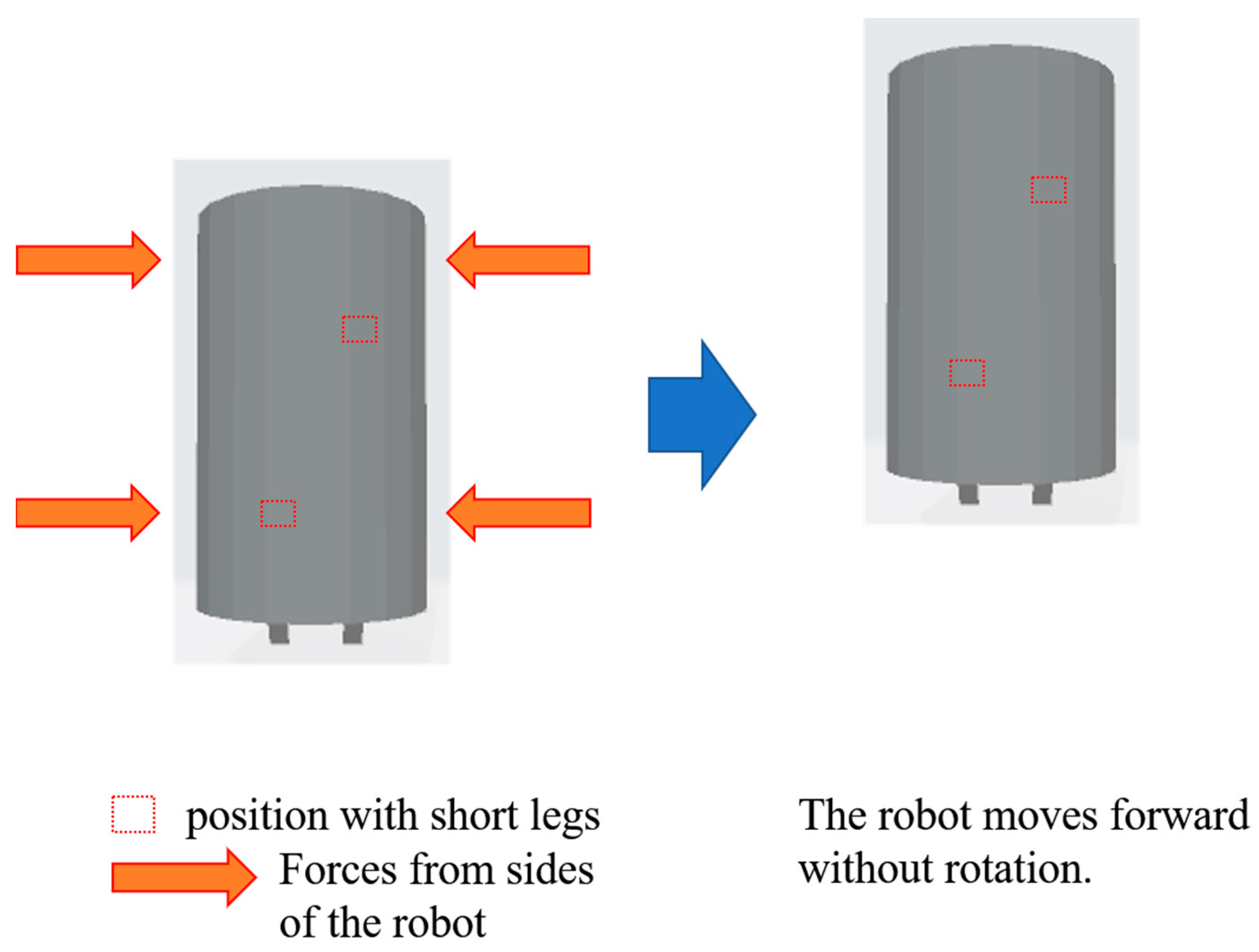
Figure 16.
Robot control experiment using frequency control. We changed the frequency from 200 Hz to 800 Hz. At first, the robot rotated from direction D to direction A when a 200 Hz sound was generated. Then, the robot moved forward to A when the sound frequency was changed from 200 Hz to 800 Hz.
Figure 16.
Robot control experiment using frequency control. We changed the frequency from 200 Hz to 800 Hz. At first, the robot rotated from direction D to direction A when a 200 Hz sound was generated. Then, the robot moved forward to A when the sound frequency was changed from 200 Hz to 800 Hz.

Disclaimer/Publisher’s Note: The statements, opinions and data contained in all publications are solely those of the individual author(s) and contributor(s) and not of MDPI and/or the editor(s). MDPI and/or the editor(s) disclaim responsibility for any injury to people or property resulting from any ideas, methods, instructions or products referred to in the content. |
© 2024 by the authors. Licensee MDPI, Basel, Switzerland. This article is an open access article distributed under the terms and conditions of the Creative Commons Attribution (CC BY) license (https://creativecommons.org/licenses/by/4.0/).
Share and Cite
MDPI and ACS Style
Niwano, T.; Matsumoto, M. Non-Electrically Driven Acoustic Actuator. Actuators 2024, 13, 148. https://doi.org/10.3390/act13040148
AMA Style
Niwano T, Matsumoto M. Non-Electrically Driven Acoustic Actuator. Actuators. 2024; 13(4):148. https://doi.org/10.3390/act13040148
Chicago/Turabian StyleNiwano, Takeru, and Mitsuharu Matsumoto. 2024. "Non-Electrically Driven Acoustic Actuator" Actuators 13, no. 4: 148. https://doi.org/10.3390/act13040148
Note that from the first issue of 2016, this journal uses article numbers instead of page numbers. See further details here.