Abstract
Currently, the textile industry is a poorly automated sector, due in part to problems in the handling of deformable leather and textile parts during production operations. In this work, several problems in the handling process of leather and textile parts are addressed, introducing methods to increase the automation of the process. A pneumatic actuator designed to pick up textile or leather parts avoiding their deformation during transport has been developed. This actuator maximizes the number of gripping points to improve handling, making it more stable and efficient. Additionally, a vision system has been implemented in the part-picking task which, in conjunction with the CAD information of the part, sends the modified gripping position of the part to the robot. This allows customized handling of each textile or leather part. Finally, validation tests have been carried out on this development, both in simulations and in laboratory conditions, demonstrating its viability and direct applicability in the production line.
1. Background
In today’s textile industry, leather pieces are manually sorted post-cutting, either by type or product, such as footwear or accessories. This process is known as kitting [1,2,3]. Kitting involves assembling all product parts into a package, known as a kit, to reduce the assembly time and boost productivity. Figure 1 illustrates the process of extracting cut parts from a piece of leather. Figure 1a shows the leather with the cut pieces, with random orientations to make the most of the leather, the cut is very thin, and this will be a problem when it comes to locating the pieces because they cannot be identified using computer vision. In contrast, Figure 1b illustrates the extracted pieces sorted into piles of the same type, leaving an empty leather skin that can be recycled.
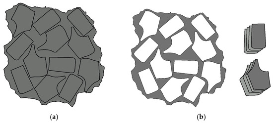
Figure 1.
Visual description of project’s objective, starting from (a) to obtain (b) automatically.
1.1. Industry Automatization
The handling of textile pieces is becoming highly automated, enhancing system efficiency and process performance. To automate a production plant, an optimized design for automated lines and robots is essential [4]. In this line, robots are being incorporated into production lines to automate industrial processes [5]. According to a study carried out in [6], the use of robots for sewing and assembly in the textile industry has significantly enhanced production speed and accuracy. Robotics allows for 24/7 operation, reducing production times and improving final product quality. A research article [7] notes that computer-aided sewing (CAD) robots have demonstrated high accuracy in garment manufacturing, which has led to a significant decrease in material waste and a reduction in associated costs. In terms of inventory management efficiency, one study [8] shows how robotics and automation have enabled the real-time monitoring of stock levels through IoT-based sensors. This has optimized inventory management, allowing companies to adjust their production according to demand and reduce warehousing costs. A review article [9] highlights that robotics in the textile industry enhances sustainability by allowing more efficient resource use and reducing energy and raw material consumption.
Robotics, especially through pick-and-place systems, has transformed the textile industry by efficiently handling and placing materials in production, automating tasks and being crucial in textile manufacturing. A recent study [10] has highlighted the impact of pick-and-place systems in the textile industry. Equipped with advanced sensors and computer vision, pick-and-place systems in the textile industry swiftly and accurately handle materials like fabric cuts, positioning them for the next production stage. This automation reduces production times, minimizes errors, and enhances garment quality. It also allows for the flexible production of customized products, adapting quickly to market demands and trends. By automating repetitive tasks, workers focus on creative and value-added activities, boosting job satisfaction and innovation. These systems exemplify how robotics improves efficiency, quality, and flexibility, being critical to the industry’s growth and competitiveness. The findings in [10] and other similar research underscores the importance of this technology in the contemporary textile industry. It is also relevant to mention the study [11,12] which highlights the time optimization in pick-and-place applications in footwear production. Another study [13] was conducted to optimize the execution of simultaneous tasks by multiple robots in a shared space. In [14] the authors showcase a system for automating and simulating robot tasks in producing carbon-fiber materials, highlighting its potential to enhance aerospace manufacturing. The research aimed to minimize total time and avoid collisions by using Markov Decision Processes (MDP).
1.2. Handling of Flexible Pieces in the Industry
In the field of textile manufacturing, automating the pick-and-place of cut textiles is complex due to potential deformation, leading to handling failures. Research is focused on solving these problems. In [15] the authors develop a robotic gripper with soft tips to simulate the human grip. The primary goal is to attain the stability and robustness of a human-like gripper using a straightforward and affordable gripping device. In [16], the authors introduce a robotic system designed to execute pick-and-place tasks involving flexible objects. The system employs a structured light scanner to create a point cloud representation of the object intended for grasping. In [16], a parallel gripper equipped with a strap embedded in a blade is developed for passive pulling operations. This gripping mechanism is adept at lifting thin, flexible items individually. The belt’s smooth surface, integrated within the blade, offers significant flexibility to conform to the object’s shape, allowing the system to handle a wide variety of workpieces effectively. The authors of [17] aim to highlight the obstacles encountered in automating the handling of materials and scrutinize the principal design approaches utilized in pick-and-place systems. This includes examining strategies for handling, reconfigurability, gripping technologies, and the distribution of gripping points, among other aspects.
1.3. Actuators in the Leather and Textile Fashion Industry
In the textile industry, grippers are vital for automating fabric handling and assembly, allowing for the precise and efficient movement of materials. Recent advances have led to the development of grippers tailored for textile automation. In [18] a brief review of the different gripper categories is presented. The objective of this article is to provide a brief informative overview of the different classifications, as proper gripper selection plays a vital role in the efficiency and performance of the robotic manipulator. In [19] the authors provide a detailed overview of the current status of robotic grippers, gripping and sensor-based control methods.
A widely used actuator in industry is the pneumatic actuator, in [20,21] the authors introduce a four-finger pneumatic soft gripper that comes in two sizes and offers four modes of gripping. A fiber-reinforced bending actuator is utilized to replicate the functionality of the soft gripper finger. Additionally, hydraulic actuators are mentioned as an alternative option in this context, in [22] a new hydraulic robotic gripper called WLRG-I (the first generation of wheeled robotic grippers) is introduced that can handle large loads and is very robust. The gripper can grip objects weighing 20 kg with a dead weight of 2.15 kg. To the authors’ knowledge, robotic grippers with such a high load-to-weight ratio are very rare. Finally, one of the most commonly used solutions for textile materials is suction cups, in [23] an experimental modeling approach is introduced, which takes into account the dynamic deformation behavior of vacuum grippers when interacting with specific combinations of grippers and objects. In [24] POLYPUS, a groundbreaking gripper was designed with under-actuation and vacuum technology; it facilitates the handling of objects regardless of their shape or material, such as plastic, metal sheets, glass, and cardboard. Unlike traditional grippers that are limited to specific weights, POLYPUS has the versatility to lift items ranging from lightweight to heavyweight. Its innovative modular design ensures that it can be quickly adjusted to accommodate a variety of object sizes and operational needs. Reference [25] introduces methods to predict the gripping forces of a specialized granular gripper for diverse objects, aiming to improve automation in manufacturing with minimal testing.
The porosity of textile materials presents significant challenges in the context of automation, particularly in robotic handling operations such as picking. Porosity affects the way a material can be gripped, as it alters the contact surface and friction between the material and the robot end-effector. The textile industry commonly does not use vacuum cups (Figure 2a) for handling due to textile porosity. The technology used to allow this manipulation is the needle gripper (Figure 2b), which uses a needle mechanism to pick up the piece for manipulation. The main problem with these grippers is that they can damage the grain side of leather materials, so the gripping technology must be adapted to the managed material.
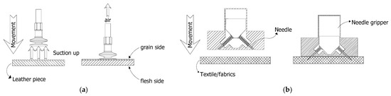
Figure 2.
Gripping point techniques: (a) based on suction cups and (b) based on needle actuators.
This research introduces a novel approach for handling flexible or deformable textile pieces by gripping them at multiple points, making them effectively rigid during transport. A specially designed tool with an array of gripping points ensures no deformation. The tool’s design, featuring numerous gripping points, and its control system, which adjusts for each piece’s shape by recalculating the tool’s position and orientation, allow for the manipulation of deformable pieces in the textile and leather industry.
The article is structured as follows: In Section 1, the solutions adopted to the problem of cutting and handling textile pieces will be presented. It will begin with a brief description of the Nesting process (Section 2.1) and then address the main problem by adopting a suction cup array actuator as a solution (Section 2.2). Then, the Contour Scanning (Section 2.3) and Computer vision system (Section 2.4) processes will be detailed. In Section 3, the results in simulation and in a real test will be presented. Finally, the conclusions will be presented in Section 4.
2. Design and Prototyping of the Suction Cups Array Actuator
In the process of cutting and the subsequent handling of textile pieces, different tasks are performed, in this context this research will address the problem of handling textile pieces in order to improve the pick-and-place process in the industry.
Firstly, the problem of the flexible piece’s placement task is addressed, in this line a suction cup array actuator has been developed in order to perform the task in the most efficient way possible. This actuator incorporates an algorithmic process that analyzes the piece and positions itself by means of rotation and translation in order to perform the place, maximizing the number of suction cups (or needle actuators) that will pick up the part. As can be seen in Figure 3, the outer contour of the piece can be detected with Machine Vision, but the pieces that have been cut on the inside by the cutting machine are not able to be differentiated because the machine cut is a very fine cut. After performing robustness tests, it was observed that the detection of some parts was partial and the detection of interior parts by artificial vision was not sufficiently robust. Therefore, a program has been developed which, through the CAD of the nesting and the detection of the whole contour, sends to the robot the position and orientation of the pieces to pick them up.
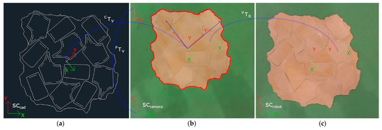
Figure 3.
(a) Nesting design in CAD and textile material (leather), (b) Computer vision recognition. (c) change of coordinate system.
2.1. The Nesting Process and Pieces Location
Nesting [26,27,28], in textile manufacturing is a key strategy that goes beyond the simple arrangement of cut patterns on a material. Its key point lies in optimizing the placement of pattern pieces on a roll of fabric or sheet of material in order to minimize the associated costs while simultaneously minimizing the waste generated during the cutting process. In the production of garments and other textile products, the effective application of nesting algorithms has become an essential pillar to achieve optimal levels of efficiency. These algorithms, developed based on optimization principles and heuristic algorithms, play a crucial role in determining the most efficient arrangement of pattern pieces, thus ensuring that the least possible amount of material is used. Figure 3 shows the Nesting design in the CAD format and once cut on the textile material. As can be seen, the coordinate system for each piece and that of the leather piece for the CAD is different from that of the image taken by vision, so a coordinate system conversion will have to be made.
The identification and location of pieces within the original sheet (see Figure 4) cannot be performed solely through computer vision, due to two very relevant factors. On the one hand, the cut is usually so fine that the silhouette of the cut piece cannot be distinguished. On the other hand, pieces have the same color as the background (the same material from which they are cut), generating no contrast of pieces with their surroundings. This makes it very difficult to locate the pieces only by vision. However, in this work, the CAD file used by the CNC cutting machine to cut the pieces is available. This CAD file can be opened and read from a Python program to obtain the position and orientation of the pieces with respect to the CAD coordinate system (SCcad).
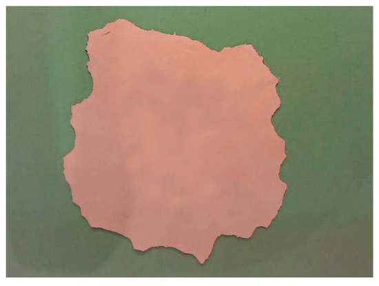
Figure 4.
Sheet of leather immediately after being cut with a very thin blade.
Through computer vision, the outer contour of the entire original sheet can be located, so when the correspondence between the CAD contour and that of the piece acquired by vision (CTv) is found, the positions and orientations of the cut elements are known precisely, and they can be picked up by the robot tool. This concept is the main contribution of the project, and it has allowed us to mix CAD information with computer vision to obtain the position and orientation of elements that are not recognized in processing the image. Figure 3 shows a sheet of material (leather) immediately after being cut. Internal pieces cannot be visually recognized due to the extremely thin cut performed by the machine blade. Images shown in Figure 3b,c depict the same sheet of material, cut and manipulated by authors many times.
When performing rotation and translation transformations, as shown in Figure 4, a series of equations are used to transform the coordinate systems. Rigid transformations are movements in space that preserve the shape and size of an object and are essential for understanding how objects move. These transformations consist of rotations and translations, which can be mathematically represented as a pair of a rotation matrix (1), which is a 2 × 2 matrix, and a translation vector (t).
The multiplication of these transformations follows a specific rule that is not commutative. This indicates that the final result is affected by the order of operations. The inverse transformation allows for the calculation of reverse trajectories, which is essential in robotics and motion planning. To simplify the composition of multiple transformations, a 3 × 3 matrix representation (2) is used that integrates both rotations and translations for calculation purposes.
This representation can be equally adapted for two-dimensional vectors by converting them to three-dimensional vectors, which allows for their inclusion in the unified mathematical framework. For example, assuming , it can be converted to a 3-dimensional vector (3).
These equations facilitate the conversion of coordinate systems between the CAD and the vision system, enabling the corresponding pick of each part. Figure 4 displays the detected part outline after converting the coordinate systems between the CAD and the images captured by the camera and processed by the artificial vision system.
2.2. The Actuator: Suction Cups Array Actuator
The pick-and-place process, essential in automated manufacturing environments, demands a specialized tool capable of performing the task quickly and efficiently. In this context, suction cups emerge as an outstanding choice to perform these tasks with precision and speed. In this project, a suction cup array actuator has been designed that manipulates the piece preventing it from deforming during transport, allowing it to be considered as rigid during the handling process.
This suction cup array actuator is composed of a matrix of 16 suction cups arranged in a non-symmetrical and non-homogeneous way in order to be able to perform different picks. This design translates into a highly versatile tool adaptable to different sizes and shapes of parts, providing different picks depending on the orientation of the part. The integration of this suction cup array actuator not only simplifies the task but also contributes to the overall optimization of the pick-and-place process. The combination of speed, accuracy and simultaneous handling capability makes this tool an advantageous component for continuous improvement in the automation of piece handling in industrial environments.
Figure 5 illustrates part of the tool design process using Solid-Works. The implementation shown corresponds to the vacuum gripper implementation, while the needle gripper implementation is equivalent. It can also be observed in the different views how the positioning of the suction cups is not symmetrical to adapt to the various shapes of the pieces. Figure 6 presents the exploded view of the components of the same implementation, providing greater detail and several zoom views of the most representative elements.
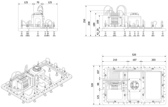
Figure 5.
Design of the suction cups array actuator: elevation, plan, and profile together with perspective view.
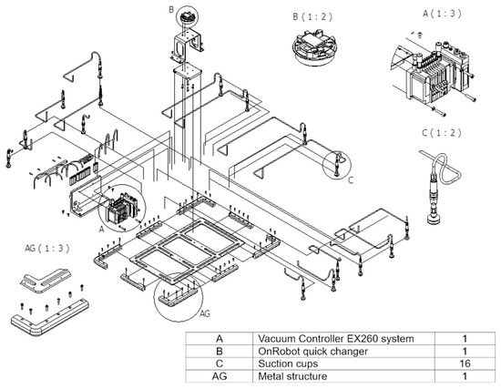
Figure 6.
Exploded-view drawing of tool components with element details.
2.2.1. Implementation of a Suction Cups Array Actuator: Hardware
This research has tested a vacuum actuator designed to manipulate flexible objects. The distribution of the gripping points allows a uniform distribution of the grabbing forces, minimizing the risk of slippage or detachment during the manipulation task. This compact and lightweight design allows us to use it with low-end-effector payload robots. In this case, a Universal Robots UR5 has been used, so the weight of the tool must be below 5 kg. In any case, the less the tool weighs, the faster it can be moved by the robot without bypassing the robot’s safety limits. Figure 7a shows the irregular distribution of the suction cups used for the tool and Figure 7b shows the final weight of the tool.

Figure 7.
Suction cups array actuator implementation detail: (a) Non-symmetrical distribution of the actuator suction cups and (b) Final weight of the tool: 3.18 kg.
The sixteen suction cups are distributed on a light frame, as shown in Figure 7a. To optimize object manipulation, the distance of each suction cup from the center of the coordinates of the frame has been determined, considering as a reference the junction with the robot end effector. This information is essential to work with the matrix and ensure optimal precision in the manipulation operations.
Figure 8 provides a clear visual representation of the spatial arrangement of the suction cups in relation to the center of the structure, as well as the plan, elevation, and profile of the actuator. The actuator gripper is protected at its edges by a padded liner firmly attached to the tool frame. A quick changer from OnRobot [29], capable of changing tools in less than 5 s, is connected to the suction cup tool; this adapter has been incorporated to change the actuator quickly if necessary due to the size or shape of the pieces or the requirements of the task. Each of the sixteen suction cups is connected via tubing to a five-way solenoid valve. The choice of these solenoid valves, specifically of the JSY1000 series [30]. This is based on its ability to significantly reduce the size, thanks to its high flow rate, thus contributing to efficient space management and reducing the overall weight of the system.
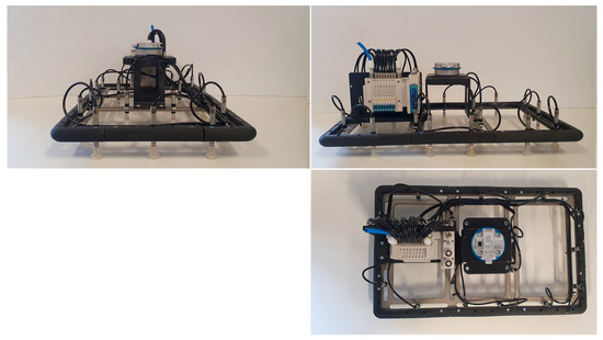
Figure 8.
Elevation, plan, and profile of the suction cups array implementation.
An EX260 system, which operates via a fieldbus, has been used to control the suction cups. This communications link allows synchronization and control of gripping and handling operations. In terms of the control interface, the suction cup array actuator is controlled by a computer running programs in Python, as this is the language in which the algorithm has been developed.
2.2.2. Optimized Use of the Tool: Software 1.0
The actuator is designed to pick pieces of different shapes and sizes by varying the orientation of the tool. To further develop this task, software has been developed that optimizes the number of suction cups per part, i.e., it calculates which orientation the suction cups array actuator should have in order to pick up the piece with the maximum number of suction cups, thus improving the pick-and-place task, as shown in Figure 9.
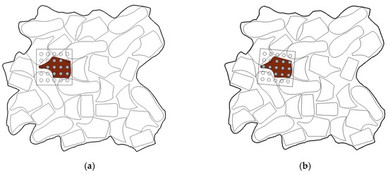
Figure 9.
Gripper of a piece with a generic matrix gripper (circles are the vacuum cups and brown piece is the pick piece): (a) Gripping by assigning the position and orientation of the workpiece to the robot end effector: seven gripping points, and (b) Gripping of the workpiece by rotating and moving the tool to maximize the number of gripping points: 11 gripping points.
The function of maximizing the grip points of each piece has been conducted by creating a Python function that returns the position and orientation with which the end effector must be corrected to perform the grip. This function has been generated using the Visual Studio Code editor. The packages necessary to achieve the required functionality have been added as development progressed. The packages used to create the program in Python were:
- ezdxf 1.0.3: Python interface to the DXF format, developed by Autodesk. Allows developers to read and alter existing DXF documents or to create new DXF documents [31].
- Math 3.2.: A module that offers access to mathematical functions as defined by the C standard C language. This includes functions for representation and number theory, powers and logarithms, trigonometric functions, hyperbolic functions, special functions, and mathematical constants [32].
- Matplotlib 3.8.1.: A comprehensive library designed for generating static, animated, and interactive visualizations in Python [33].
- NumPy 1.26.1: Library that defines a data type representing multidimensional arrays, having basic functions to work with. It is a stable and fast library [34].
- Shapely 2.0.1: A Python package utilized for the set-theoretic analysis and manipulation of planar features, leveraging the functionalities of the GEOS library [35].
The development of the program has been structured in three steps. The first step deals with the preparation of the images for processing in the Python code, using AutoCAD. Obtaining the silhouette of the piece is essential, and for this purpose a specific procedure has been followed to guarantee its appropriate interpretation in the Python code. In this process, we have worked exclusively with straight lines connected in the required order, excluding the use of circles, semicircles, or splines.
The second step of the program presents the various functions developed for the code, dealing with the manipulation and analysis of the matrices associated with the pieces obtained. Each function has been designed with the purpose of maximizing the number of suction cups coinciding with the part.
Finally, the third step shows the “Driver Code”, which coordinates and executes the previously defined functions. The process is performed by mediating a DXF file created in AutoCAD containing the piece to be picked. The program processes the file and displays the points that make up the resulting polygon. In addition, the center of the polygon is calculated using the “centroid” function. This systematic and detailed approach facilitates obtaining matrices with the maximum number of suction cups activated within the part, thus contributing to the efficiency of the system in the manipulation of objects.
The center of the piece is shown in the graph by a star. The position of the suction cup array actuator has been moved to the center of the part; the suction cups are represented by a cross inside a circle (Figure 10).
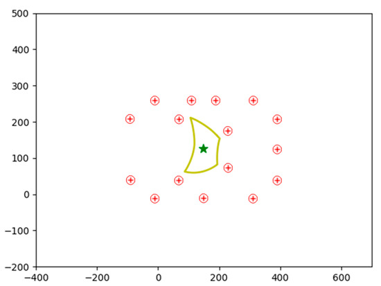
Figure 10.
Center of the tool represented in the center by a star (so gripping point at that point). Red points are the available vacuum cups. In yellow the piece.
Next, the first step of the displacement, known as translation is carried out. In this phase, a process of optimizing the translation of the actuator in the space occupied by the part is carried out in order to calculate the suction cups to be used, maximizing the number of suction cups. This process is shown in Figure 11.
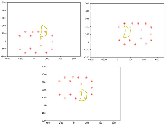
Figure 11.
Process for finding the optimal configuration. Red points are the available vacuum cups. In yellow the piece.
Once the first step is completed, the analysis and calculation of the matrices with the highest number of active suction cups inside the piece is carried out, as well as the identification of the activated suction cups in each matrix. In addition, the number of arrays that meet the requirement of the maximum number of active suction cups, set at 2 in the shown example is determined; the coordinates used to move the array are recorded. When the translation phase is completed, the rotation phase is carried out using the matrices obtained in order to maximize the number of active suction cups inside the leather piece. These matrices are rotated around their axis, thus generating new configurations (see Figure 12 for more information on the process). After calculating the rotation matrices with the highest number of active suction cups inside the part, the active suction cups in each matrix, the total number of selected matrices, and the coordinates associated with each configuration are recorded. In this case, the maximum number of active suction cups is kept at 2, both in the rotation and translation phases. This increase in the number of dies offers a variety of options when selecting the optimal position for piece handling.
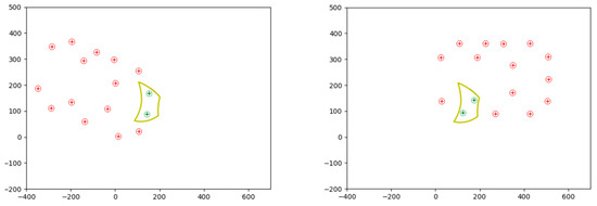
Figure 12.
Selection of the actuator arrangement according to the selected suction cups (Green points). Red points are the available vacuum cups. In yellow the piece.
Figure 13 shows a flowchart of the program developed to carry out the process presented. Software tests have been carried out for different sizes and dimensions of pieces as shown in Figure 14, with satisfactory results.
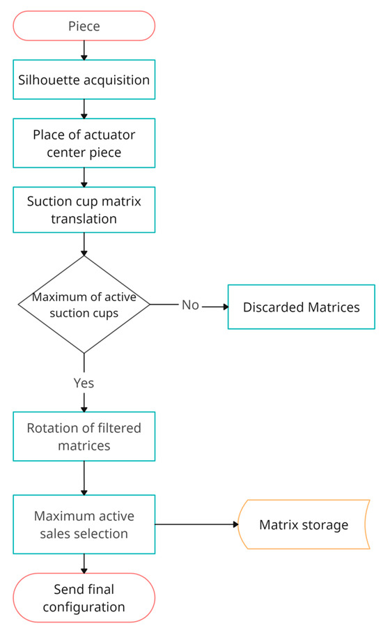
Figure 13.
Flowchart of the code developed in Python.
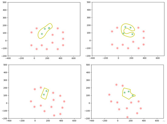
Figure 14.
Process for finding the optimal configuration of various parts.
2.3. Contour Scanning
Once the Nesting is conducted on the textile material in the computer-aided manufacturing process, obtaining data from the pieces to be collected is fundamental; for this AutoCAD is used as the main tool. In addition to extracting data from the pieces according to the model sent for cutting on the CNC machine, detailed information on the uncut base is obtained, thus providing a complete set of data for the production process. For the extraction of piece data, the AutoCAD EXTRACDAT command is used. This command allows for the specific selection of the required data from the templates, thus simplifying access to them from a programming environment such as Python. The data extracted include the template model, essential for classification, as well as the X and Y coordinates and rotation of each of the templates. The process to obtain these data starts with the use of the EXTRACDAT command in AutoCAD, generating a structured text file that stores the selected information. These data are essential for the classification and organization of the production process.
They also facilitate the traceability of each piece throughout the manufacturing chain. Once the data have been obtained from AutoCAD, the next step involves the manipulation of the cropped image centered on the part. Transformations are applied to identify the contour of the part. This contour, once obtained, provides valuable information, including the center of the part. The correlation of this center with that obtained during AutoCAD data extraction establishes a coordinate system to facilitate the subsequent piece processing. In addition, the eigenvectors of the contour are obtained. These vectors, which coincide with the axes of inertia of the figure are used to extract the orientation and shape of the part.
2.4. Computer Vision System
After the textile or leather sheet has undergone the cutting process, the coordinates of each piece cannot be extracted by vision as has been mentioned before. The complexity lies in the fact that the cut is so fine that it is impossible to differentiate each piece by vision. Therefore, it is necessary to resort to the information contained in the CAD file of the Nesting. The coordinates and rotation angles of the individual pieces can be extracted from the CAD file. First of all, the CAD and the image taken by vision must be matched. This is because the center of coordinates of the CAD does not have to coincide with the center of coordinates of the vision captures. Once the translation and rotation between the CAD and the vision capture are known, the rotation-translation matrix will be applied to locate the pieces in the robot’s workspace.
The objective of this piece is to locate the textile piece on the conveyor belt using machine vision. Once the position of the plate is known, the data can be extracted from AutoCAD and the transformations described in Section 2.1 can be applied. This procedure allows for correcting small positioning errors that may occur due to the movement of the plate on the conveyor belt. At the same time, the correspondence of the AutoCAD, camera and robot coordinate systems is calculated. The algorithm starts by reading the image that has been taken during the simulation. This image is cropped in such a way that all the pixels around the piece that are not interesting, such as the sides of the tape are removed. So, the image is centered on the textile piece from which it must extract information. Once the image is cropped and centered on the piece, several morphological transformations are performed to detect the contour of the piece. From this contour, the center of the contour is obtained, with which a first relation of the coordinate system with the center obtained in the AutoCAD data extraction can be made. In addition, you can also obtain the value of the eigenvectors of the contour, which coincide with the axes of inertia of the figure that are also extracted from AutoCAD.
With the above-mentioned data, it is possible to calculate whether the piece has been rotated with respect to AutoCAD. By having the eigenvectors of the axes both from AutoCAD and from the outline extracted from the image, the axes can be drawn on the image and the rotation and translation between the coordinate systems can be calculated. In the cropped image it can be seen and in the outline of the part, the center and the axes have been drawn. In this case, the rotation is 0 degrees, so the piece has not changed its orientation during the movement of the ribbons.
3. Results and Discussion
3.1. Simulation Results
This section describes the simulation process of the workstation with representative images. Figure 15 shows the complete station before starting the simulation. The sequence starts with the introduction of the uncut leather into the CNC for processing according to the specified cutting pattern (Figure 15a). After cutting, the re-cut pieces move along the rolling mat until they reach the collection area where an image of the cut base is captured. Once the capture is conducted, the Python algorithm is started. The first step involves obtaining data both for each individual piece and the uncut base directly from AutoCAD. Subsequently, all piece data are recalculated to establish relationships with the data obtained from the captured image. After this recalculation process, the phase of sending data from Python to RobotStudio begins. It is imperative that the robot has been positioned in the waiting area for the start of the collection before this step. From RobotStudio, the signal is sent to initiate the socket communication and start sending data. Figure 15b shows the robot in a waiting position to receive the first data. The robot executes the pick-and-place task by picking up each piece and depositing it in a pile together with other pieces of the same cutting pattern. This strategy ensures proper sorting in the case of having several cut models. This simulation process integrates the interaction between the CNC machine, the Python algorithm, and the robot in RobotStudio, showing a pick-and-place operation and the correct sorting of the collected parts.
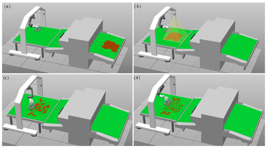
Figure 15.
Complete simulated process: (a) Nesting and piece cutting, (b) machine vision, (c) pick-and-place, (d) end pick-and-place.
Figure 15c illustrates the moment when the robot performs the task of picking a piece and moving it to the corresponding place. The sequence culminates with the correct pick-up of all the parts, depositing them one by one in the designated pile together with the rest of the pieces of the same model, all aligned in the same orientation. In Figure 15, the result of the process is presented in Figure 15d, showing all the collected templates in an organized manner. This closure visualizes the efficiency of the system in completing the handling of the pieces and their successful sorting, demonstrating the ability of the workstation to perform pick-and-place operations in an autonomous and orderly manner.
3.2. Real Tests
The process starts with the operator inserting the uncut textile piece into the CNC machine, indicating the CAD file model to be cut. Figure 16 shows the piece inserted and ready for cutting. Once positioned, the CNC is activated and performs the cut, generating the different cut pieces. Subsequently, these pieces move on the CNC rolling mat, as shown in Figure 16, until they reach the position where the algorithm starts to extract data from AutoCAD, capture the image and send the data to the robot. The algorithm starts with the extraction of data from each template as well as from the base to establish the relationship between the piece on the table and the AutoCAD data. With all the data extracted, the visual recognition process is started. The camera is activated and records, storing the frames in a folder. When the operator indicates that the piece is in place or a specific time has elapsed, the recording stops, and the algorithm starts reading the last 15 frames.
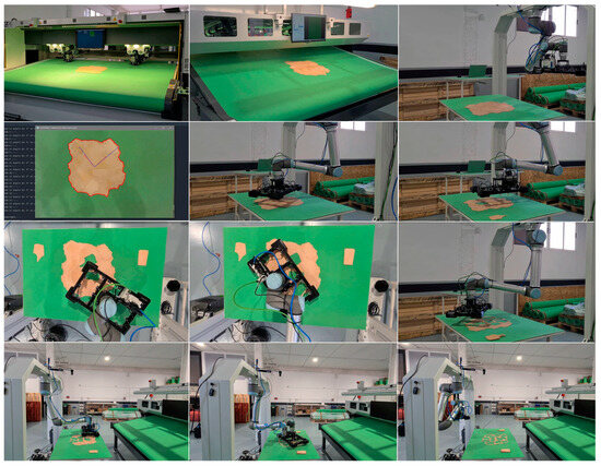
Figure 16.
Real setup: Set of frames extracted from the video that shows how the system works. These 16 frames depict the entry of a leather piece into the cutting machine, its exit and how the robot equipped with the tool developed in this project manages cut pieces successfully.
In each of the 15 frames, the morphological transformations are applied to detect the contour of the piece and determine the angle of rotation with respect to the AutoCAD data. After calculating all the iterations, the algorithm discards results that indicate anomalous angles. Finally, an image of the detected con-torque and the axes of the base in AutoCAD and the actual rotated base is displayed on the screen. Figure 4 shows the resulting image and the on-screen message with the angle of rotation. This approach combines CNC accuracy with visual recognition capability, allowing precise alignment of the cut pieces with the AutoCAD data prior to manipulation by the robot. The algorithm then recalculates all the template positions and rotation angles required to send the instructions to the robot accurately. This step is essential to ensure proper handling of each cut part. Afterward, the robot establishes a connection via the socket, waiting to receive a message from the robot controller with the template number to be sent. This approach facilitates synchronization between the algorithm and the robot, allowing a coordinated execution of the process. With the connection established, the algorithm sends the data for each piece to the robot sequentially. Once the sending of data for all pieces is completed, the robot returns to its initial position, awaiting the next pick-and-place process. Figure 16 illustrates the end of the process where all pieces have been picked and sorted according to the model that has been cut. This closure visualizes the efficiency of the system in the coordination of the cutting, visual recognition, and robotic handling operations.
This video shows the entire process described: https://youtu.be/GJxV3TP_N2E (accessed on 6 February 2023).
4. Conclusions
This paper deals with the automation of processes in the textile and clothing industry, especially in the robotic sorting of CNC cut parts. A non-symmetrical suction cup array actuator has been developed and tested, complemented with a vision system and algorithms for the handling of textile parts. The results obtained both in simulations and in industrial plant environments highlight the efficiency and practical applicability of this technology in real production environments. Traditionally, the handling of textiles in industrial environments has been a challenge due to their deformable and varied nature. This project addresses these challenges effectively, enabling the more precise handling adapted to the specific characteristics of each textile piece. In addition, the integration of a vision system and image processing algorithms allows for more accurate and automated sorting and handling, representing a significant step towards the modernization of the textile industry. Experiments have focused on specific textile types and handling conditions. The development of the suction cups array actuator allows the activation of the suction cups in an individual way, using an algorithm to maximize the gripping points to perform the task of picking up the part, in this way the actuator moves to the position and angle that maximizes the suction cups to pick up the piece so that it does not deform during the trajectory towards the place position. When the pieces are cut and need to be transferred, the computer vision system cannot differentiate the pieces due to their thin cut, this problem is addressed by matching the CAD generated by the nesting and the recognition of the external contour of the leather made by vision; by means of a rotation-translation matrix, the correct data are sent to the robot so that it can carry out the pick-and-place task. The applicability of this technology in the textile and leather industry has been confirmed through experiments in simulated production environments, reaching TRL 4.
Author Contributions
Conceptualization, F.J.M.-P., J.B.M., J.V.S.H. and C.P.-V.; methodology, J.V.S.H. and C.P.-V.; software, F.J.M.-P. and J.B.M.; validation, F.J.M.-P. and J.B.M.; formal analysis, J.V.S.H. and C.P.-V.; investigation, J.B.M. and F.J.M.-P.; resources, J.B.M.. and F.J.M.-P.; writing—original draft preparation, F.J.M.-P., J.B.M., J.V.S.H. and C.P.-V.; writing—review and editing, F.J.M.-P., J.B.M., J.V.S.H. and C.P.-V.; visualization, F.J.M.-P. and J.B.M.; supervision, J.V.S.H. and C.P.-V.; project administration, C.P.-V.; funding acquisition, C.P.-V. All authors have read and agreed to the published version of the manuscript.
Funding
This research has been partly funded by project CPP2021-008593, grant MICIU/AEI/10.13039/501100011033 and by the European Union-NextGenerationEU/PRTR.

Data Availability Statement
Data are contained within the article.
Acknowledgments
This project has been performed in collaboration with CFZ Cobots SL (https://cfzcobots.com/), (accessed on 12 January 2024) a company devoted to create software solutions in combination with hardware implementations for integrators and engineering companies.
Conflicts of Interest
The authors declare no conflicts of interest.
References
- Brynzér, H.; Johansson, M. Design and performance of kitting and order picking systems. Int. J. Prod. Econ. 1995, 41, 115–125. [Google Scholar] [CrossRef]
- Hanson, R.; Medbo, L. Kitting and time efficiency in manual assembly. Int. J. Prod. Res. 2012, 50, 1115–1125. [Google Scholar] [CrossRef][Green Version]
- Hanson, R.; Brolin, A. A comparison of kitting and continuous supply in in-plant materials supply. Int. J. Prod. Res. 2013, 51, 979–992. [Google Scholar] [CrossRef]
- Méndez, J.B.; Cremades, D.; Nicolas, F.; Perez-Vidal, C.; Segura-Heras, J.V. Conceptual and Preliminary Design of a Shoe Manufacturing Plant. Appl. Sci. 2021, 11, 11055. [Google Scholar] [CrossRef]
- Borrell, J.; González, A.; Perez-Vidal, C.; Gracia, L.; Solanes, J.E. Cooperative human–robot polishing for the task of patina growing on high-quality leather shoes. Int. J. Adv. Manuf. Technol. 2023, 125, 2467–2484. [Google Scholar] [CrossRef]
- Smith, A.; Johnson, B.; Brown, C. Robotic Automation in Textile Industry: Advancements and Benefits. J. Text. Eng. Fash. Technol. 2020, 6, 110–112. [Google Scholar]
- Lee, S.; Kim, H. Precision Sewing with Computer-Aided Robotic Systems in Textile Manufacturing. Int. J. Robot. Autom. 2019, 34, 209–218. [Google Scholar]
- Wang, Y.; Liu, H.; Zhang, Q. IoT-Based Inventory Management in Textile Manufacturing: A Case Study. J. Ind. Eng. Manag. 2021, 14, 865–878. [Google Scholar]
- García, L.; Pérez, M.; Rodríguez, J. Sustainability Benefits of Automation in the Textile Industry. J. Sustain. Text. 2018, 5, 94–105. [Google Scholar]
- Chen, X.; Wu, Z.; Li, J. Robotic Pick-and-Place Systems in Textile Manufacturing: A Review of Efficiency and Quality Improvements. Robot. Autom. Rev. 2022, 18, 45–56. [Google Scholar]
- Mendez, J.B.; Perez-Vidal, C.; Heras, J.V.S.; Perez-Hernandez, J.J. Robotic Pick-and-Place Time Optimization: Application to Footwear Production. IEEE Access 2020, 8, 209428–209440. [Google Scholar] [CrossRef]
- Borrell, J.; Perez-Vidal, C.; Segura, J.V. Optimization of the pick-and-place sequence of a bimanual collaborative robot in an industrial production line. Int. J. Adv. Manuf. Technol. 2024, 130, 4221–4234. [Google Scholar] [CrossRef]
- Mateu-Gomez, D.; Martínez-Peral, F.J.; Perez-Vidal, C. Multi-Arm Trajectory Planning for Optimal Collision-Free Pick-and-Place Operations. Technologies 2024, 12, 12. [Google Scholar] [CrossRef]
- Körber, M.; Glück, R. A Toolchain for Automated Control and Simulation of Robot Teams in Carbon-Fiber-Reinforced Polymers Production. Appl. Sci. 2024, 14, 2475. [Google Scholar] [CrossRef]
- Jørgensen, T.B.; Jensen, S.H.N.; Aanæs, H.; Hansen, N.W.; Krüger, N. An Adaptive Robotic System for Doing Pick and Place Operations with Deformable Objects. J. Intell. Robot. Syst. 2019, 94, 81–100. [Google Scholar] [CrossRef]
- Morino, K.; Kikuchi, S.; Chikagawa, S.; Izumi, M.; Watanabe, T. Sheet-Based Gripper Featuring Passive Pull-In Functionality for Bin Picking and for Picking Up Thin Flexible Objects. IEEE Robot. Autom. Lett. 2020, 5, 2007–2014. [Google Scholar] [CrossRef]
- Björnsson, A.; Jonsson, M.; Johansen, K. Automated material handling in composite manufacturing using pick-and-place system—A review. Robot. Comput. Manuf. 2018, 51, 222–229. [Google Scholar] [CrossRef]
- Samadikhoshkho, Z.; Zareinia, K.; Janabi-Sharifi, F. A Brief Review on Robotic Grippers Classifications. In Proceedings of the 2019 IEEE Canadian Conference of Electrical and Computer Engineering (CCECE), Edmonton, AB, Canada, 5–8 May 2019; pp. 1–4. [Google Scholar]
- Zhang, B.; Xie, Y.; Zhou, J.; Wang, K.; Zhang, Z. State-of-the-art robotic grippers, grasping and control strategies, as well as their applications in agricultural robots: A review. Comput. Electron. Agric. 2020, 177, 105694. [Google Scholar] [CrossRef]
- Ye, Y.; Cheng, P.; Yan, B.; Lu, Y.; Wu, C. Design of a Novel Soft Pneumatic Gripper with Variable Gripping Size and Mode. J. Intell. Robot. Syst. 2022, 106, 5. [Google Scholar] [CrossRef]
- Zhang, X.; Yu, S.; Dai, J.; Oseyemi, A.E.; Liu, L.; Du, N.; Lv, F. A Modular Soft Gripper with Combined Pneu-Net Actuators. Actuators 2023, 12, 172. [Google Scholar] [CrossRef]
- Qi, J.; Li, X.; Tao, Z.; Feng, H.; Fu, Y. Design and Control of a Hydraulic Driven Robotic Gripper. In Proceedings of the 2021 IEEE International Conference on Robotics and Biomimetics (ROBIO), Sanya, China, 27–31 December 2021; pp. 398–404. [Google Scholar]
- Gabriel, F.; Fahning, M.; Meiners, J.; Dietrich, F.; Dröder, K. Modeling of vacuum grippers for the design of energy efficient vacuum-based handling processes. Prod. Eng. 2020, 14, 545–554. [Google Scholar] [CrossRef]
- Maggi, M.; Mantriota, G.; Reina, G. Introducing POLYPUS: A novel adaptive vacuum gripper. Mech. Mach. Theory 2022, 167, 104483. [Google Scholar] [CrossRef]
- Wacker, C.; Dierks, N.; Kwade, A.; Dröder, K. Analytic and Data-Driven Force Prediction for Vacuum-Based Granular Grippers. Machines 2024, 12, 57. [Google Scholar] [CrossRef]
- Heckmann, R.; Lengauer, T. A simulated annealing approach to the nesting problem in the textile manufacturing industry. Ann. Oper. Res. 1995, 57, 103–133. [Google Scholar] [CrossRef]
- Chryssolouris, G.; Papakostas, N.; Mourtzis, D. A decision-making approach for nesting scheduling: A textile case. Int. J. Prod. Res. 2000, 38, 4555–4564. [Google Scholar] [CrossRef]
- Alves, C.; Brás, P.; de Carvalho, J.V.; Pinto, T. New constructive algorithms for leather nesting in the automotive industry. Comput. Oper. Res. 2012, 39, 1487–1505. [Google Scholar] [CrossRef]
- OnRobot: Quik Changer. Available online: https://onrobot.com/es/productos/quick-changer (accessed on 11 December 2023).
- Electric Vacuum: JSY100. Available online: https://www.smcworld.com/catalog/New-products-en/mpv/es11-113-jsy-np/data/es11-113-jsy-np.pdf (accessed on 11 December 2023).
- Introduction—Ezdxf 1.0.3 Documentation. (s. f.). Available online: https://ezdxf.readthedocs.io/en/stable/introduction.html (accessed on 11 December 2023).
- Math—Mathematical Functions. (s. f.). Python Documentation. Available online: https://docs.python.org/3/library/math.html (accessed on 11 December 2023).
- Matplotlib—Visualization with Python. Available online: https://matplotlib.org (accessed on 11 December 2023).
- NumPy—Bioinformatics at COMAV 0.1 Documentation. (s. f.). Available online: https://bioinf.comav.upv.es/courses/linux/python/scipy.html (accessed on 11 December 2023).
- The Shapely User Manual—Shapely 2.0.1 Documentation. (s. f.). Available online: https://shapely.readthedocs.io/en/stable/manual.html (accessed on 11 December 2023).


Disclaimer/Publisher’s Note: The statements, opinions and data contained in all publications are solely those of the individual author(s) and contributor(s) and not of MDPI and/or the editor(s). MDPI and/or the editor(s) disclaim responsibility for any injury to people or property resulting from any ideas, methods, instructions or products referred to in the content. |
© 2024 by the authors. Licensee MDPI, Basel, Switzerland. This article is an open access article distributed under the terms and conditions of the Creative Commons Attribution (CC BY) license (https://creativecommons.org/licenses/by/4.0/).