Article

Development of the Anthropomorphic Arm for Collaborative and Home Service Robot CHARMIE

1
Mechanical Engineering Department, University of Minho, 4800-058 Guimarães, Portugal
2
LIACC, University of Maia, 4475-690 Maia, Portugal
3
Centro ALGORITMI, University of Minho, 4800-058 Guimarães, Portugal
*
Author to whom correspondence should be addressed.
Actuators 2024, 13(7), 239; https://doi.org/10.3390/act13070239
Submission received: 17 May 2024 / Revised: 22 June 2024 / Accepted: 24 June 2024 / Published: 26 June 2024

Abstract

:
Service robots are rapidly transitioning from concept to reality, making significant strides in development. Similarly, the field of prosthetics is evolving at an impressive pace, with both areas now being highly relevant in the industry. Advancements in these fields are continually pushing the boundaries of what is possible, leading to the increasing creation of individual arm and hand prosthetics, either as standalone units or combined packages. This trend is driven by the rise of advanced collaborative robots that seamlessly integrate with human counterparts in real-world applications. This paper presents an open-source, 3D-printed robotic arm that has been assembled and programmed using two distinct approaches. The first approach involves controlling the hand via teleoperation, utilizing a camera and machine learning-based hand pose estimation. This method details the programming techniques and processes required to capture data from the camera and convert it into hardware signals. The second approach employs kinematic control using the Denavit-Hartenbergmethod to define motion and determine the position of the end effector in 3D space. Additionally, this work discusses the assembly and modifications made to the arm and hand to create a cost-effective and practical solution. Typically, implementing teleoperation requires numerous sensors and cameras to ensure smooth and successful operation. This paper explores methods enabled by artificial intelligence (AI) that reduce the need for extensive sensor arrays and equipment. It investigates how AI-generated data can be translated into tangible hardware applications across various fields. The advancements in computer vision, combined with AI capable of accurately predicting poses, have the potential to revolutionize the way we control and interact with the world around us.

1. Introduction

In recent years, robots have increasingly become integral parts of daily human life, with a growing demand for their presence in both domestic and industrial settings. Consequently, numerous research efforts across various labs are yielding remarkable results. To effectively replicate human actions in humanoid robots, a sufficient number of degrees of freedom (DOF) is necessary to achieve anthropomorphic functionality. Typically, humanoid robot arms require 7 DOF from the shoulder to the wrist to perform most human motions, while hand DOF can range from 5 to 24, depending on the necessary motions [1]. Notable examples of such robots include NASA’s Robonaut Arm, ARMAR-III humanoid platforms, the LIMS2 lightweight robot arm, and JUSTIN [2,3,4].
Robots have undergone several iterations and improvements to reach this point. The first major anthropomorphic arm was the Rancho Anthropomorphic Manipulator (RAM), designed in 1972. The human hand, a very complex mechanism, saw its first major robotic evolution with the Belgrade Hand, created in 1963 by Professor Rajko Tomović at the Serbian Academy of Sciences and Arts (SANU) in Belgrade, Serbia. The Belgrade Hand was fitted with the Minsky arm from MIT and NASA’s JPL Ames teleoperator arm [5]. These advancements led to the development of the Salisbury Hands, which had sensory capabilities to handle delicate objects [6].
In 1993, Campbell Aird became the first cyborg human by using the Edinburgh Modular Arm System, created at Margaret Rose Hospital in Edinburgh, UK. Aird’s new arm could move in various orientations, mimicking a human arm [7]. Recent developments in this field are remarkable. The most advanced anthropomorphic hand today is the OpenAI hand, which can solve a Rubik’s Cube single-handedly [8]. OpenAI utilized AI to enable the hand to learn how to actuate in difficult situations to achieve the desired result.
Further advancements include LIMS1 [9] and LIMS2 [3], which presented dual arms capable of high-speed manipulations while maintaining a lower overall mass. LIMS1 weighed 3.37 kg with an inertia of 0.57 kgm2. In the area of hand development, the most notable and extensive work is the Design of the Highly Biomimetic Anthropomorphic Arm by Zhe Xu and Emanuel Todorov. This work studied the hand from a biomimetic perspective and replicated its kinematics, with joints capable of flexion, abduction, and opposition, closely mimicking actual joint movements [10].
This work is conducted within the development of the CHARMIE robot [11,12], tailored for domestic applications as home service and assistant robots, with social goals including settings such as nursing homes for interaction and task assistance. For this project, selecting and developing appropriate control strategies for the robot arms was imperative. Inmoov, an open-source robot with a sizable community following, features a 10 DOF robotic arm comprising 5 DOF hands, 1 DOF wrist, 1 DOF elbow, and 3 DOF shoulder [13,14].
The work is structured into three main parts: assembly, focusing on cost reduction and performance enhancement; kinematics definition, considering operational limits and designing control software for arm actuation and motion verification; and teleoperation method design, utilizing computer vision and machine learning (ML)-based hand pose estimation to control the arm’s hand.

2. Methodologies

The methodology addresses three key components of the work and details the efforts made to achieve the results. These components are: electromechanical assembly, defining the robot’s operational limits and Denavit-Hartenberg(DH) parameters, and mimicking movements through computer vision.

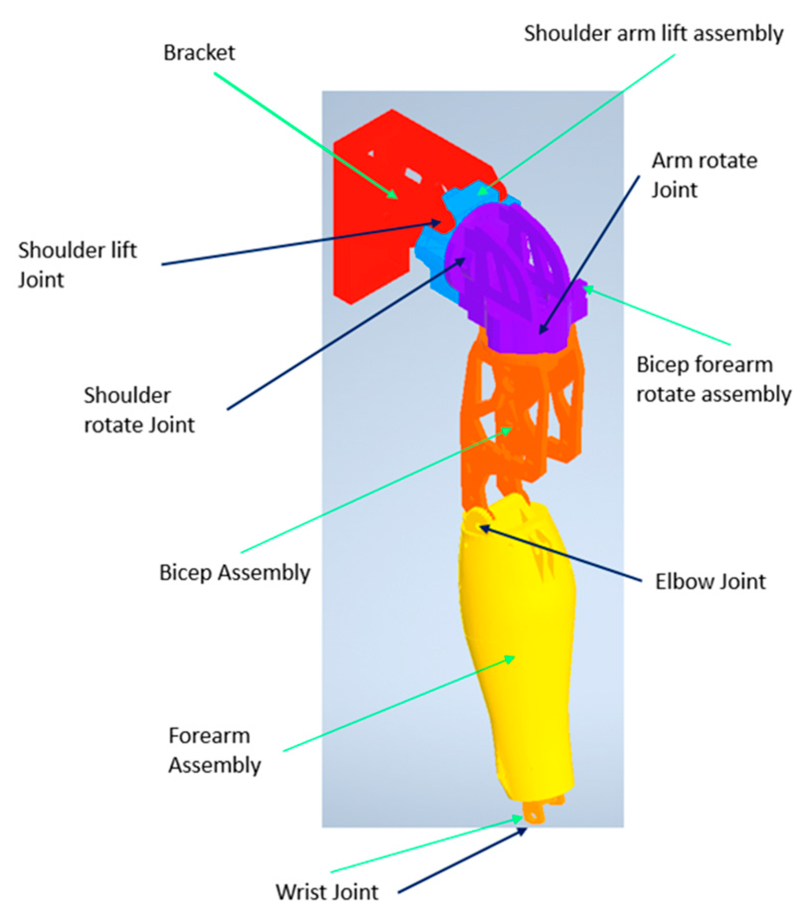
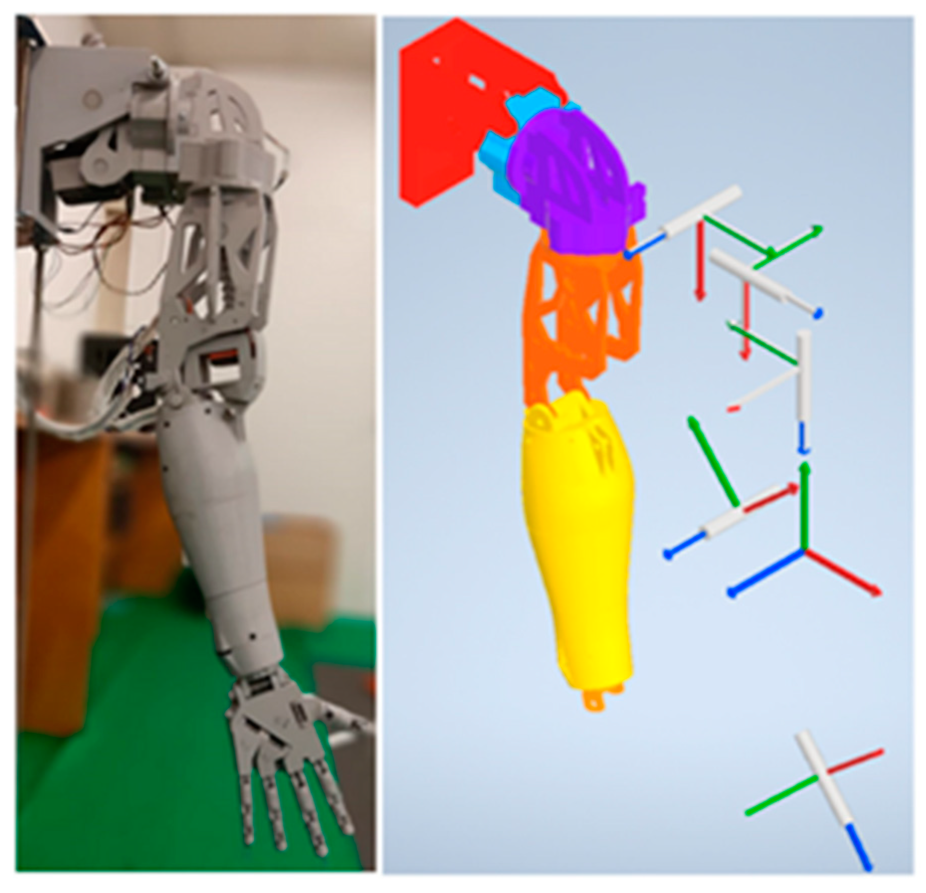
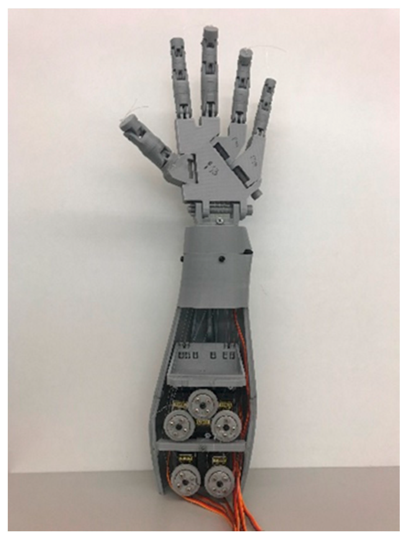
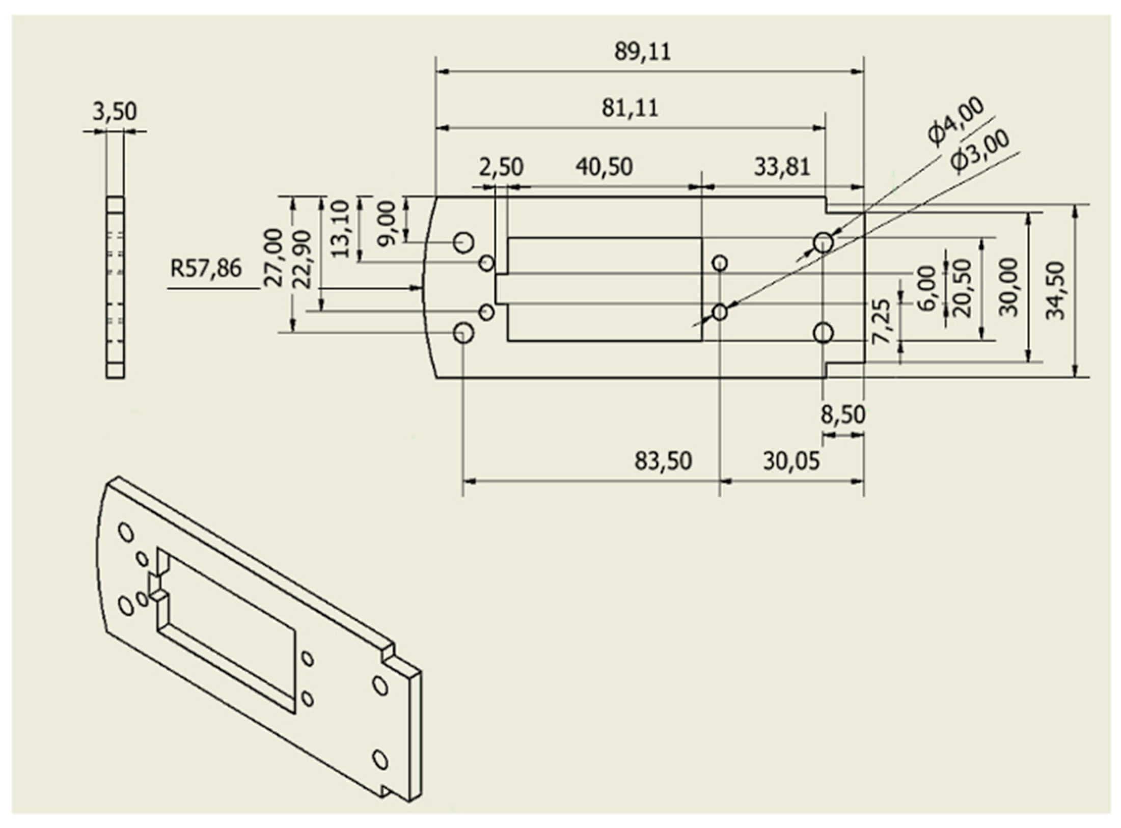
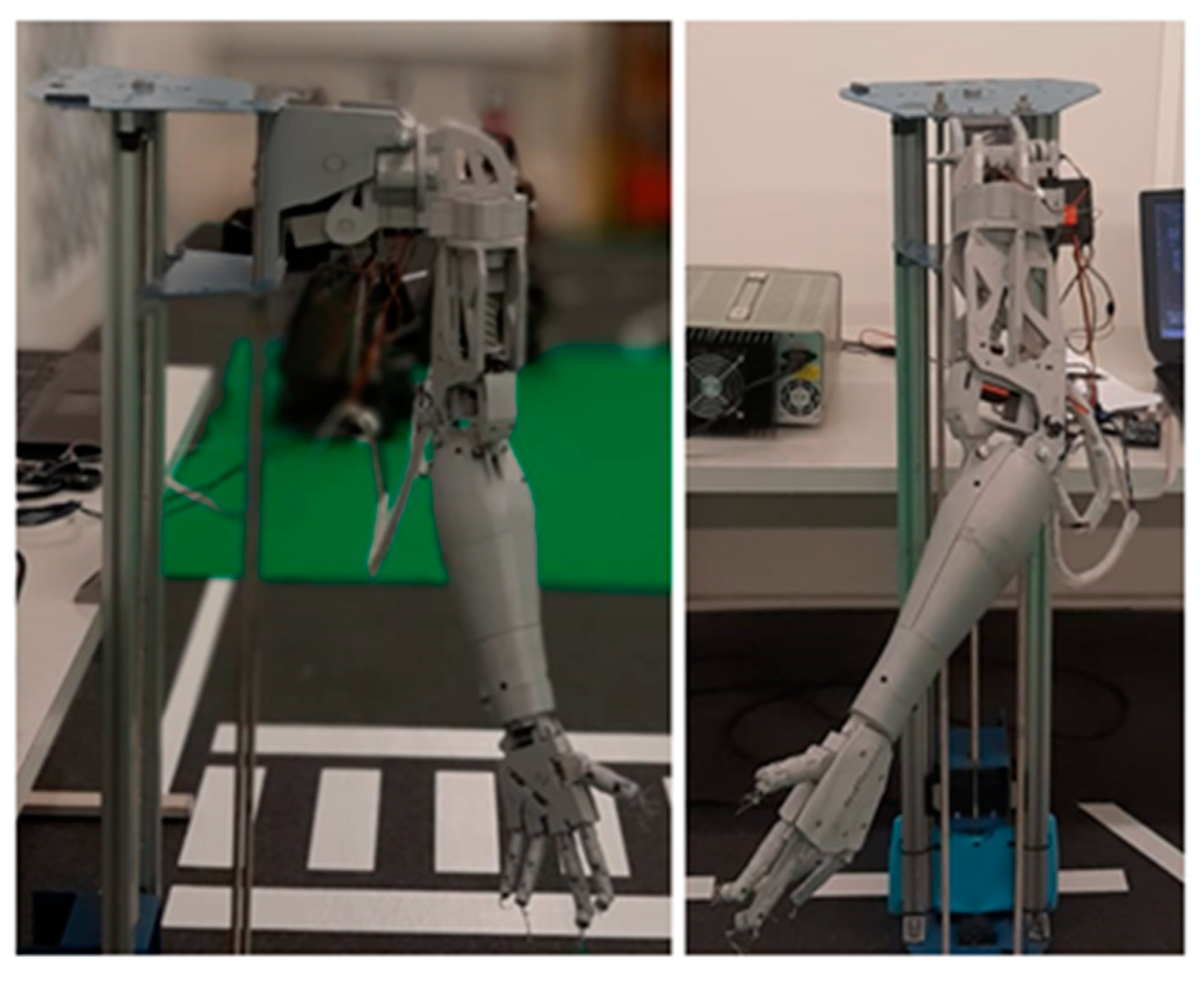
2.1. Electromechanical Build

The project began by manufacturing the parts of Inmoov, an open-source robot, adhering to the inventor’s specifications. The components were 3D printed using PLA (Polylactic Acid) with a MakerBot Replicator 2. This step ensured that the robot’s physical structure was constructed accurately and in accordance with the original design, laying the foundation for further assembly and development.
The initial modification involved replacing the original single-track pulley, known as the servo-pulley in Inmoov’s part nomenclature. According to the assembly instructions, the tension in the tendons was not consistently taut, resulting in loose tendons and imprecise movements. To address this issue, the single-track pulley was substituted with a dual-track pulley. This adjustment allowed for the rotation of the tendon motors in either direction, ensuring that the tendons remained taut and the fingers moved precisely.
The second modification involved the “GearHolder” and “gearpotentio” components, which are necessary to secure the elbow potentiometer in place.
The third modification entailed replacing the original servomotors, specifically the elbow and arm rotation servos. The initial design utilized Hitec HS-805BB servos, which were substituted with TD-8125MG servos. The new motors offered similar torque output but in a smaller form factor, enhancing the overall efficiency and compactness of the system. The total mass of the 3D-printed components amounted to 1.864 kg, while the combined mass of the motors was 0.804 kg. Consequently, the total mass of the arm was just under 2.7 kg.
The electronics assembly comprises three small circuits, with an Arduino Mega serving as the controller due to its provision of all necessary pulse width modulation pins for servo actuation. In total, there are ten servomotors: six MG996R motors for controlling finger and wrist movements, two TD-8125MG motors for elbow and arm rotation, and two Hitec HS-805BB motors for shoulder lift and shoulder rotation joints. The motors are individually actuated to determine their extreme angles. These angles (shown in Table 1) are measured based on two criteria: the electric current consumed by the motor when holding a joint position, and the overall position of the robot, crucial for collision avoidance. These angles are vital for kinematic calculations, computer vision calculations, and arm actuation. Table 2 shows the angle limits for the hand’s finger movements.
Figure 1 illustrates the different components of the arm and its respective joints, presented in a 3D CAD colored model to enhance visualization.

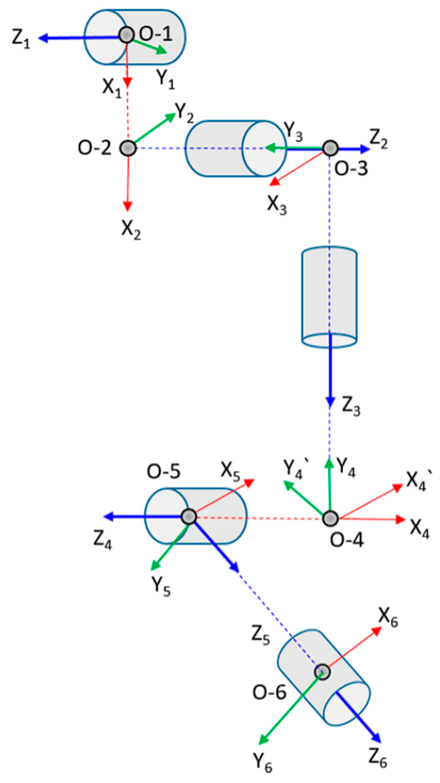
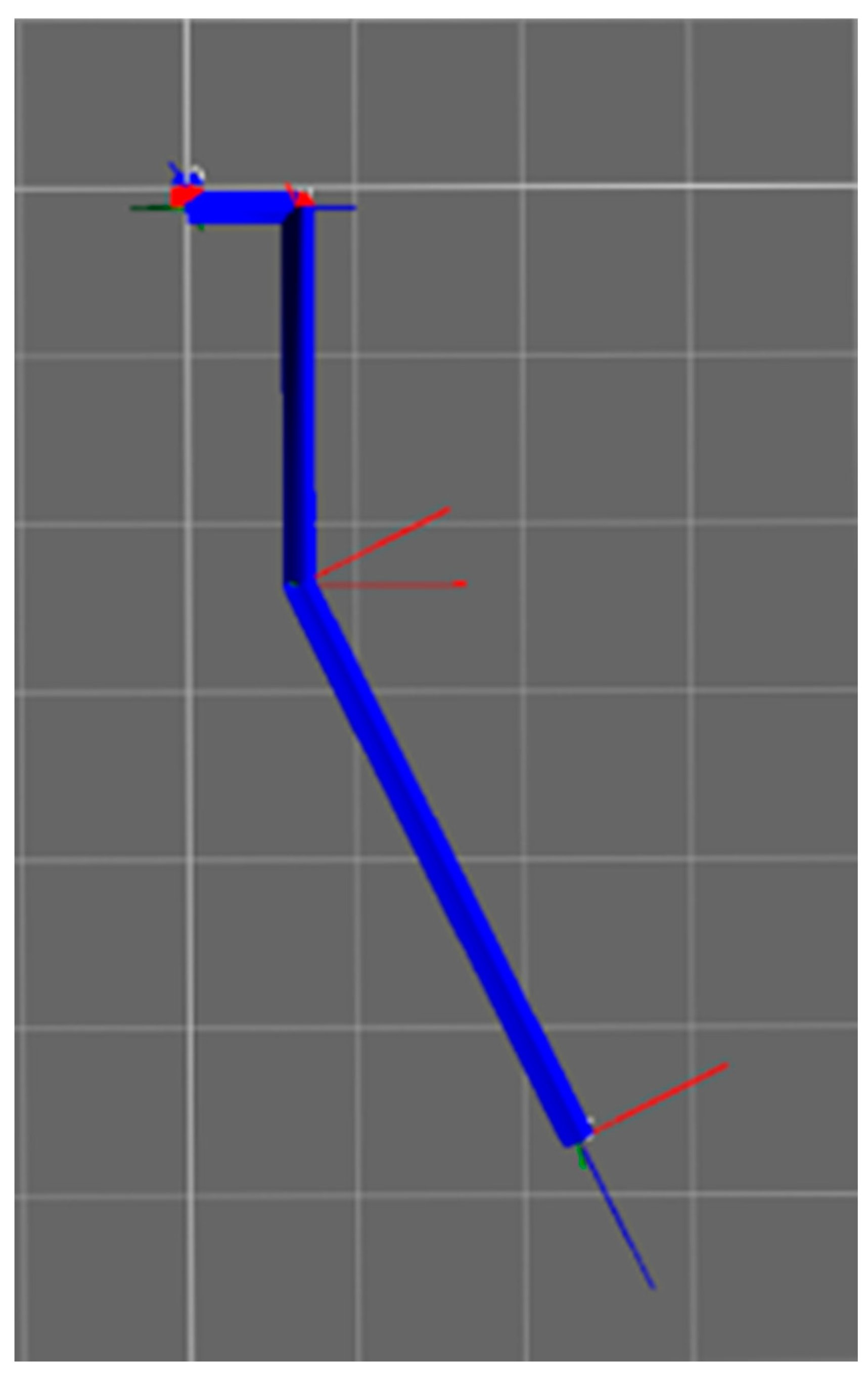
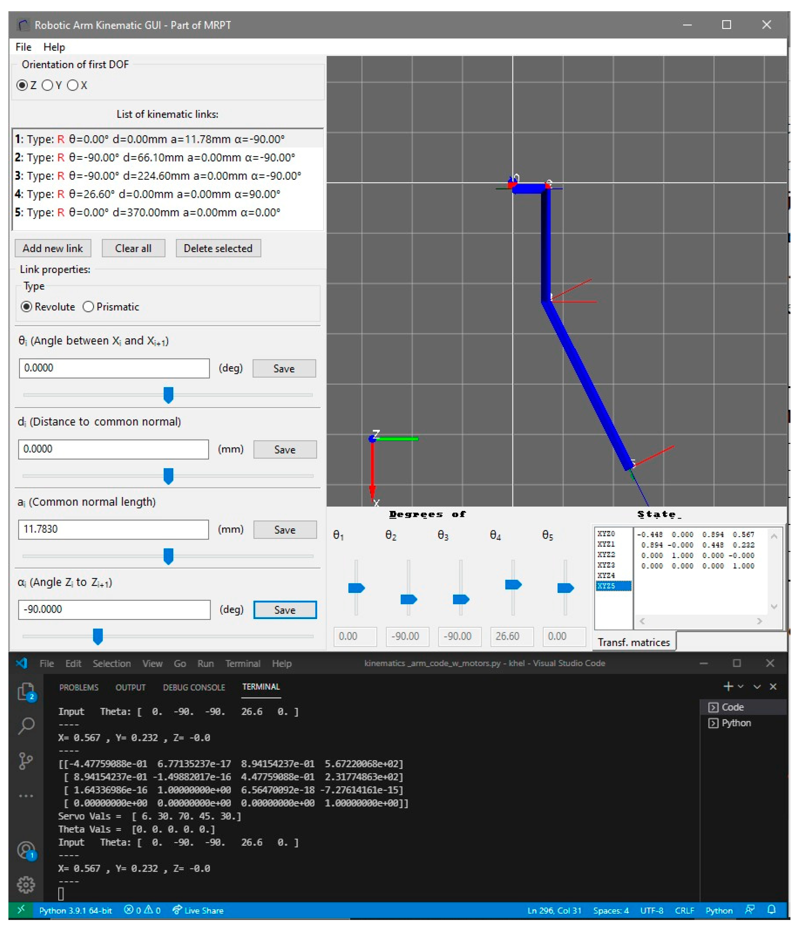
2.2. Forward Kinematics

The kinematics developed specifically pertain to the arm. The initial phase of this work involves creating an assembly in a CAD system (Figure 1) to ascertain the center of rotation and the dimensions of each joint and part.
The arm is a 5 DOF arm, calculated using Grubler’s Rule as follows:
D O F = λ N J 1 + i = 1 J F i
where, N represents the number of links, J the number of joints, Fi the degree of freedom (DOF) at the ith joint, and λ is a constant that is either 6 for 3D motion or 3 for 2D motion.
The DH equations [15] show the transformation matrix for each link, and the final transformation matrix is calculated as:
T i i 1 = R Z i 1 θ i   T Z i 1 d i   T x i α i R x i α i   = C θ i S θ i 0 0 S θ i C θ i 0 0 0 0 1 0 0 0 0 1 1 0 0 a i 0 1 0 0 0 0 1 d i 0 0 0 1 1 0 0 0 0 C α i S α i 0 0 S α i C α i 0 0 0 0 1 = C θ i C α i S θ i S α i S θ i a i C θ i S θ i C α i C θ i S α i C θ i a i S θ i 0 S α i C α i d i 0 0 0 1
where C and S are cosine and sine of the joint angle, respectively, θ is the angle of rotation around the Z-axis, α is the angle offset around the X-axis of the joint, and a and d are the joint offsets along the X and Z-axes, respectively. The subscript i represents the link number in (2).
In Equation (3), the total transformation matrix H is obtained by multiplying each individual transformation matrix T i 0 . This multiplication is represented as:
H = T i 0 = T 1 0 T 2 1 T t i 1 = T i 0 = R i 0 T i 0 0 1
Each T i 0 matrix consists of a 3 × 3 rotation matrix R i 0 and a 3 × 1 translation matrix T i 0 combined. The resulting H matrix encapsulates both the orientation (represented by R) and the position (represented by T) of the end effector with respect to the base joint.
Utilizing the CAD assembly and following the DH parameters, Table 3 shows the obtained values for each link.
The d parameter for link 5 incorporates two values combined. The first value, 289.5 mm, signifies the distance from the elbow to the wrist joint. Additionally, as the end effector is the hand and is also part of this link, an extra value of 80.5 is added to position the end effector precisely at the center of the hand.
The parameters listed in Table 3 were derived from the kinematic axis diagram depicted in Figure 2. In Figure 3, O-6 designates the end effector for the robot.
The parameters of Table 3 were calculated using an open-source software called MRPT (Mobile Robot Programming Toolkit, version 2.13.2) [16]. This software was utilized for finalizing the parameters and served as a verification tool for the Python (version 3.12.0) software developed to control the robot. The MRPT model is depicted in Figure 4.

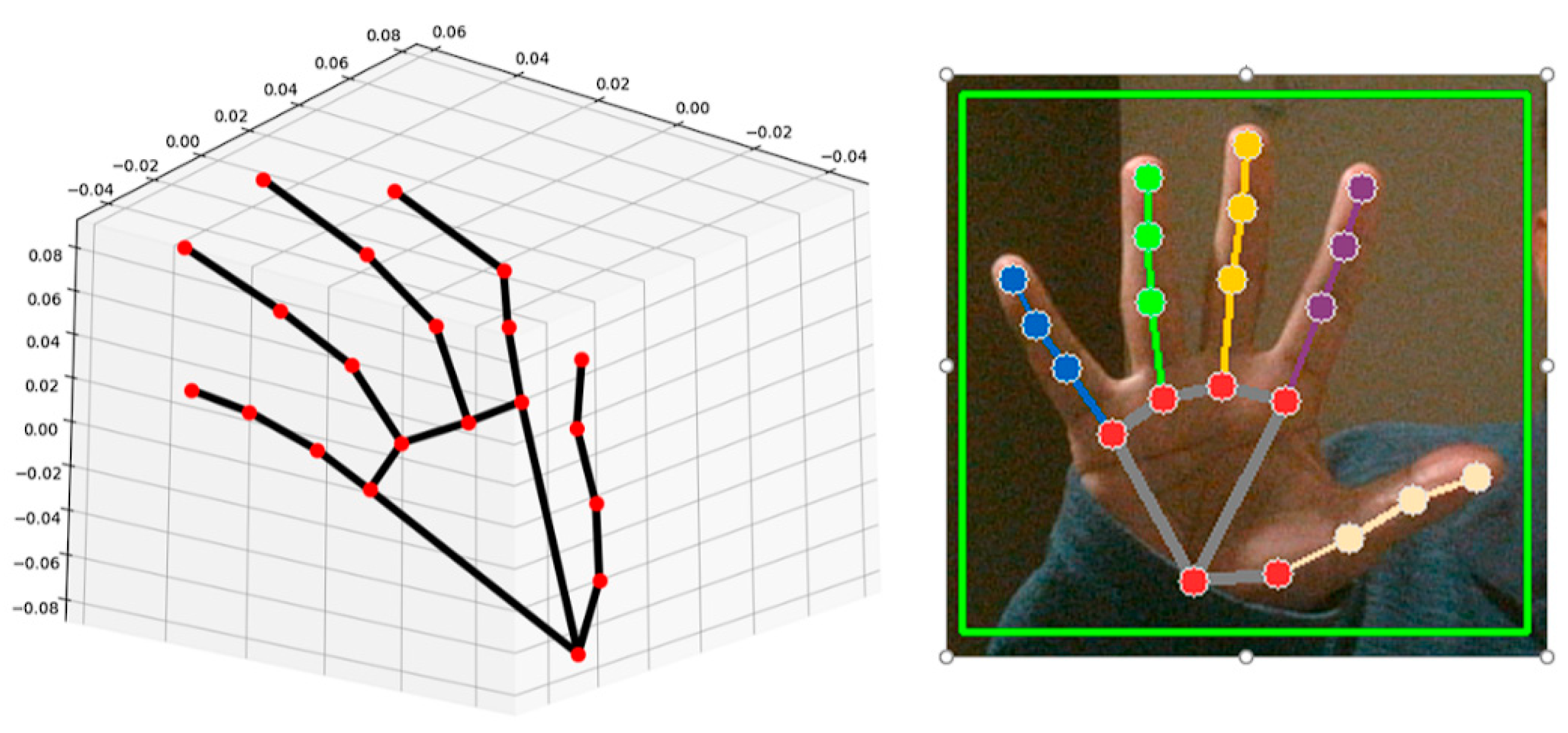
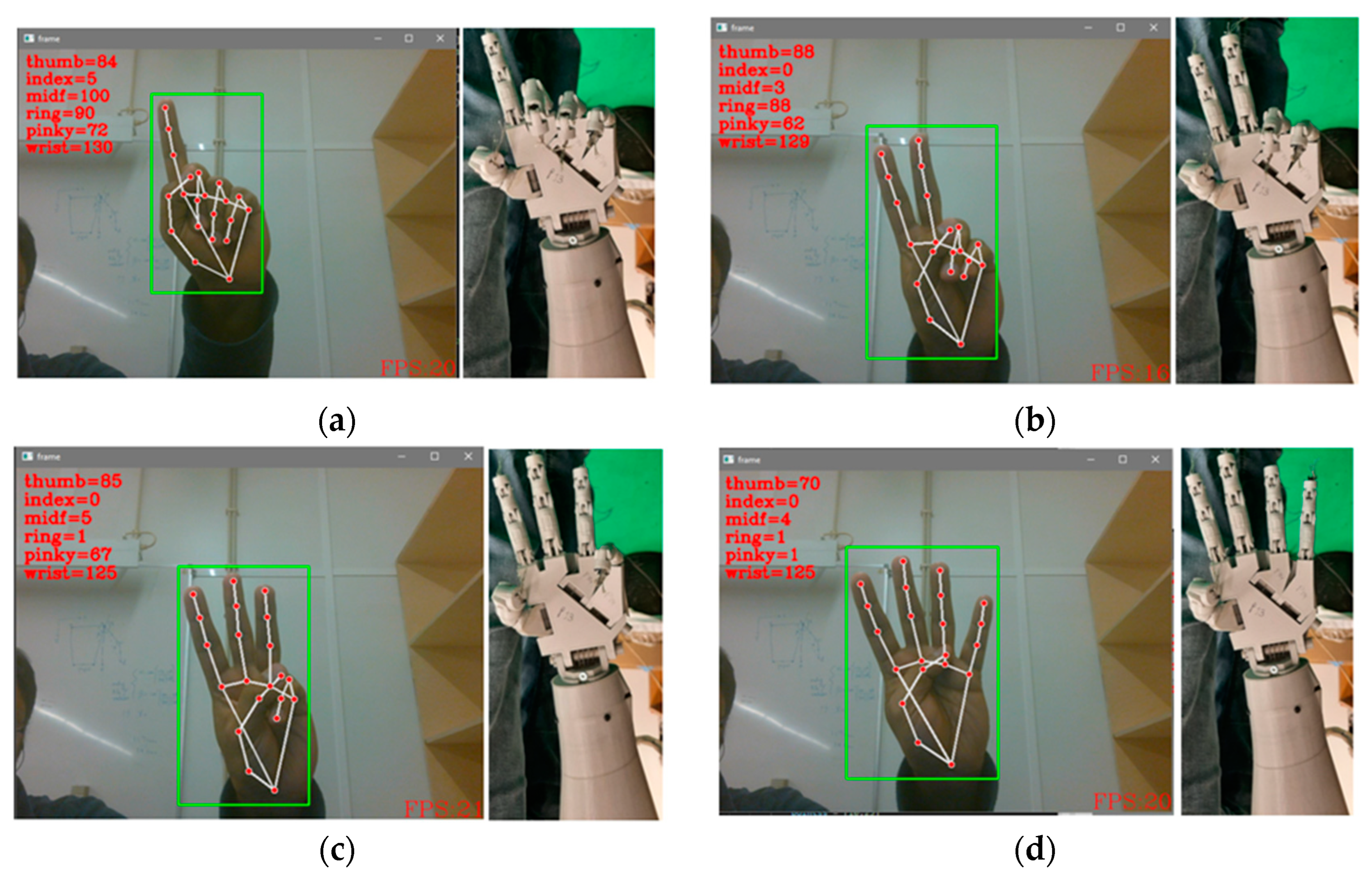
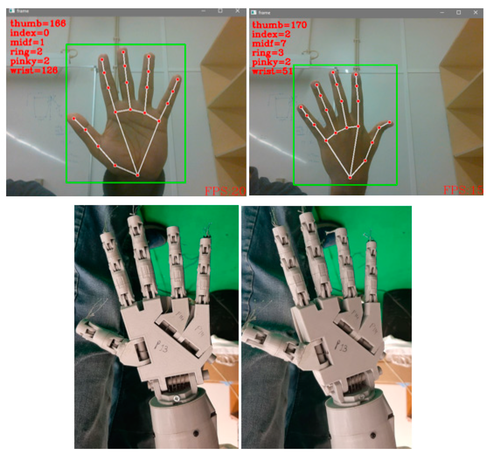
2.3. Mimicking through Vision

The primary software utilized for this phase of the project was developed in Python, leveraging the OpenCV library. Initially, the focus was on creating software capable of detecting hands within an image frame and determining their pose. Google Mediapipe [17] was adapted for pose detection (Figure 5).
To enable the robot to mimic human hand movement, several software packages were necessary. Since the robot is actuated using Arduino as the controller for servomotors, PyFirmata [18] was employed for serial communications. This software detects the Arduino’s port and sets up the servomotors as output.
Google Mediapipe requires two values to configure the detection and tracking confidence. For this project, a value of 0.7 out of 1 was selected. Various values were tested, and a value of 0.5 resulted in randomly shifting detected hand poses, while values above 0.7 proved overly restrictive and failed to detect hands in certain lighting conditions. A value of 0.7 was chosen as it provided a reasonable frame rate, ranging between 16 and 25 frames per second (fps). The program continuously receives frames from the camera, creating a bounding box to maintain the hand or hands within perspective.
The hand pose estimation also provides landmarks, which are essentially 3D points with X and Y coordinates corresponding to the video frame size. However, the Z value is a scaled value and does not represent true depth. In this estimation, the wrist serves as an anchor, with its coordinates always set to (X, Y, 0), indicating that the wrist is positioned at a depth equal to 0, or Z = 0. The coordinates of all other landmarks are referenced based on the wrist’s Z value.
To calculate the angle of finger flexion and extension, several techniques were considered and tested. Initially, one approach involved computing the Euclidean distance between the fingertips and the MCP (metacarpophalangeal) joint and relating it to the angle the finger motor can move during actuation. However, this approach failed due to variations in distance to the camera, which caused changes in the length. Similar issues occurred when employing the cosine law. Ultimately, the vector dot product method was used to determine this angle:
θ = c o s 1 a · b a b
where θ represents the angle, a and b are two vectors, and ∣∣a∣∣ and ∣∣b∣∣ are the magnitudes of these normalized vectors. For equation (4) to function correctly, the coordinates for the fingertip and MCP joint, as well as the wrist and MCP, are converted to vectors and inserted into the equation. The challenge in wrist rotation arises from its axis of rotation being the X-axis. To address this, the gradient of the line connecting the wrist to the index MCP (and similarly for the thumb MCP) is calculated and incorporated into the formula, ensuring that the denominator never reaches zero:
θ = t a n 1 m 1 m 2 1 + m 1 × m 2
where θ is the angle, m1 and m2 are the gradients. If the denominator goes to zero, the program converts the denominator to 1 thus not giving a divide-by-zero exception.
These values are then fed into an averaging filter to smooth the values of the angles calculated:
A v e r a g e   a n g l e = 1 N ! × i = 1 N i × a n g _ v a l : i + 1  
where N is the number of values taken, for the filtration N = 3 was used, ang_val is the value of a joint’s angle and i is the joint index that is i = 0 means its index finger.
These averaged values were then mapped where it takes in five values such as the actual input (averaged angle) and the two ranges of input and output, respectively:
C o n v e r t e d   V a l u e = m a x m i n o u t _ m a x o u t m a x o u t m i n i n m a x i n m i n + o u t _ m i n o u t _ m i n  
These values are sent to the Arduino microcontroller through the PyFirmata library, and the fingers actuate as per these values.

3. Results and Discussion

This chapter discusses three sections describing the results of the respective methodologies.

3.1. Electromechanical Build

The mechanical build has deviated from the original design. The major changes were the servo pulley from single track to dual track pulley as shown in Figure 6, and the tautness of the tendons was increased. The mass of all pulleys was 0.010 kg. Figure 7 shows the PLA built forearm with servomotors and respective tendons connected to the fingers.
The bicep motor plate was swapped for other servomotors and required another motor mounting plate. Figure 8 shows the new motor plate with a mass of 0.020 kg.
The elbow motor was also swapped so a new plate was designed as shown in Figure 9, with a mass of 0.020 kg.
The original motors specified in the Inmoov design were Hitec HS-805B, each with a mass of 0.152 kg. Consequently, a total reduction of 0.304 kg was achieved on the arm, offset by an additional 0.040 kg. Since the new bracket is not integrated into the arm, its mass does not affect the arm’s operation.
The two newly added motors are TD8125, with a combined mass of 0.112 kg. These new motors perform comparably and effectively, providing 2.31 Nm of torque at 4.8 V, an improvement from the previous 1.94 Nm. This also means that TD8125 is approximately 8.3-fold greater when comparing torque, having a higher payload capacity. However, one issue arising from this upgrade is that the original parts need modification to accommodate the new motors.
The motor body contributes to the rigidity of the motor holder, which is currently lacking and can be addressed by either redesigning the part (making the motor slot smaller) or filling gaps in the original part. Despite this, there is minimal vibration, and the arm operates smoothly without observable buckling or vibrations in the structure. The total mass of the arm is measured at 2.168 kg, excluding the bracket designed for mounting the arm. Including the bracket, the mass totals approximately 2.7 kg.

3.2. Forward Kinematics

The results for this section entail the results achieved by simulation and the software developed and the comparison of the simulation posture and the real-world robot. Figure 10 shows the robot’s working volume.
Following is the result of the software developed and the posture (Table 4). Table 4 basically compares the result of the simulation run by MRPT to generate the coordinate of the end effector and Python calculates the coordinates for the end effector. The figures from Figure 11, Figure 12, Figure 13 and Figure 14 along with Table 4 verifies the simulated position (MRPT), actual position (physical inspection) and Python software calculation combining Denavit-Hartenbergcalculations and potentiometer values from the servomotors.
Figure 11 and Figure 12 visually represent the robot in its default state, where none of the motors are actuated. This is the POS 1 from Table 4. In this state, the default position of the end effector is calculated and verified. This verification process encompasses both physical validations, conducted through manual examination and software-based analysis, often employing simulation techniques. This ensures that the robot’s actual configuration aligns accurately with the intended default position, as determined through calculations.
Figure 13 and Figure 14 visually depict the robot at its two-extreme position. This is the POS 5 from Table 4. The validation process involves both physical inspections, where the robot’s actual position is manually checked, and software-based analyses and utilizing simulation methods. This combined approach ensures alignment between the robot’s actual configuration and the intended position as initially calculated. Additionally, the loopback system from the servos ensures that the specified angle of any motor matches the actual angle of the corresponding joint.
Figure 12 and Figure 14 show the two extreme positions of the robot. The result shows the real-world position of the end effector as compared to the simulation (MRPT simulation vs. Python software). Through the calculations, simulation and robot actuation, the performance of the robot matches the same position in 3D space as that of the simulation as depicted in Table 4 and Figure 11, Figure 12, Figure 13 and Figure 14. Also the same can be observed in the demonstration video [19].

3.3. Mimicking through Vision

The computer vision component of the project delves into the teleoperation capability of the robot, which involves controlling the robot’s movements remotely using visual input. In practical testing, the system demonstrated satisfactory performance in terms of frames per second (fps), with a range typically falling between 16 to 25 fps. This indicates that the system can process and respond to visual input efficiently within this frame rate range.
The methodology section discusses the range of motion for the servos, which dictates how far each joint of the robot can move. It is essential to understand this range as it determines the capabilities of the robot in terms of executing different motions and gestures.
Figure 15 demonstrates the robot’s mimicking capability using a 2D camera. Notably, the motion depicted in the figures exhibits smoothness without any noticeable jittering. This indicates that the pose captured by the camera holds steady in the software, and the robot accurately complies with the captured pose to mimic it.
Figure 16 illustrates the movement of the wrist relative to the hand position. While the rotation depicted in the figure may not be extensive, as previously discussed, this limitation is deliberate to ensure the smooth functioning of the robot. By constraining the wrist rotation within a specific range, the system safeguards the robot’s operation and minimizes potential strain on its mechanical components.
In the context of hand movement, the captured visual input from the camera is important. Figure 16 provides a visual representation of the hand’s configuration, showcasing the positions of the five fingers and the overall hand posture. Additionally, it highlights the movement of the wrist.
Notably, the wrist movement does not encompass a full 180-degree actuation with respect to the servomotor. Instead, the wrist is allowed a range of motion from 0.523 radians (30 degrees) to 2.617 radians (150 degrees), totaling 2.094 radians (120 degrees), which later goes to a larger gear, thus reducing the rotation further. This limitation is intentional and stems from practical considerations regarding the mechanical structure of the hand. The load on the tendons passing through the wrist plays a significant role here, causing them to become taut or loose based on the wrist’s position. Therefore, the restricted range of motion is designed to ensure optimal functionality and stability while minimizing strain on the mechanical components.

4. Conclusions

This paper delves into the theoretical foundation and practical application of anthropomorphic arms and hands in robotics. It begins with an overview of current technologies, discussing their advantages and limitations while exploring potential applications in service and industrial robots. This study introduces the Inmoov arm and hand, detailing the 3D printing and assembly process, along with solutions to encountered challenges, highlighting avenues for cost-cutting and unconventional design approaches to achieve functional arm.
Mechanically, the arm is constructed using 3D-printed components, giving it an advantage in easy modification, fabrication, design, and faster prototyping compared to competitors that require specialized, expensive materials needing machining and metalworking. The mass of the arm significantly affects its manipulation capabilities and payload capacity. Inmoov weighs 2.168 kg, while its competitors weigh 3.7 kg [1], 4.17 kg [9], and 14 kg [4]. In comparison, Inmoov lacks the heavy payload capacity of its competitors but excels in mimicking operations similar to more advanced robots and achieving human-like motion. The Inmoov arm can handle masses up to 0.5 kg, actuated by hobby servos with lower payload capacity and a structure made from 3D-printed PLA, which lacks the robustness needed for heavy loads. In contrast, its competitors can manage significant loads up to 10 kg [9] and 14 kg [4], utilizing materials like aluminum and stainless steel for durability and strength. The mechanical design of the Inmoov arm reduces costs, manufacturing time, and assembly complexity, making it a feasible platform for developing, designing control strategies, and testing them.
The electronics for this robot are relatively simple and can be implemented on basic microcontrollers with minimal control software. In contrast, competitors employ specialized actuators with complex control circuits and dedicated software. For instance, LIMS2 [9] incorporates dedicated motors for each joint with individual control circuits and specific software, resulting in more complex control systems.
A significant novelty of this arm lies in its kinematic design and implementation. While competitors feature intricate mechanical designs requiring specialized algorithms for kinematics, the Inmoov arm benefits from the straightforward development and testing of Denavit-Hartenberg parameters which can be easily verified through simulation software and implemented in Python to be calculated and verified. Another innovation is the teleoperation of the hand, a major milestone where an AI-trained model mimics hand movement in real-time using a 2D camera [19] capturing 16–25 frames per second (fps).
Furthermore, this work serves as the groundwork for the development of the CHARMIE robot, establishing a starting point for future iterations of arms and hand control. It introduces various control strategies, including fully automated systems and methods for teleoperation. It gives a cheaper, rapid protype capable and easier to control platform for future iteration to come to a point where the arm can be manufactured with stronger materials and powerful actuators to perform desired operations. Identified areas for future improvement include enhancing robot arm actuation mechanisms, integrating advanced servomotors with improved sensors, adopting 3D cameras for better depth measurement, developing inverse kinematics for automated arm control, and refining mechanical systems for increased strength and efficiency.
Through these advancements, the aim is to refine the capabilities of anthropomorphic robots, enabling them to perform tasks with greater precision, adaptability, and efficiency in various real-world scenarios.

Author Contributions

Conceptualization, F.A.S., A.F.R. and G.L.; methodology, F.A.S.; software, F.A.S. and A.F.R.; validation, F.A.S. and A.F.R.; formal analysis, A.F.R. and G.L.; investigation, F.A.S.; resources, F.A.S.; writing—original draft preparation, F.A.S.; writing—review and editing, A.F.R. and G.L.; visualization, F.A.S.; supervision, A.F.R. and G.L.; project administration, A.F.R. and G.L. All authors have read and agreed to the published version of the manuscript.

Funding

This work has been supported by FCT—Fundação para a Ciência e a Tecnologia within the R&D Units Project Scope: UIDB/00319/2020.

Institutional Review Board Statement

Not applicable.

Informed Consent Statement

Not applicable.

Data Availability Statement

Data are contained within the article.

Acknowledgments

This work has been supported by the Laboratory of Automation and Robotics (LAR) of University of Minho, and the ALGORITMI research center.

Conflicts of Interest

The authors declare no conflicts of interest.

References

  1. Paik, J.K.; Shin, B.H.; Bang, Y.B.; Shim, Y.B. Development of an anthropomorphic robotic arm and hand for interactive humanoids. J. Bionic Eng. 2012, 9, 133–142. [Google Scholar] [CrossRef]
  2. Asfour, T.; Regenstein, K.; Azad, P.; Schroder, J.; Bierbaum, A.; Vahrenkamp, N.; Dillmann, R. ARMAR-III: An integrated humanoid platform for sensory-motor control. In Proceedings of the 2006 6th IEEE-RAS international conference on humanoid robots, Genova, Italy, 4–6 December 2006; pp. 169–175. [Google Scholar]
  3. Song, H.; Kim, Y.S.; Yoon, J.; Yun, S.H.; Seo, J.; Kim, Y.J. Development of low-inertia high-stiffness manipulator LIMS2 for high-speed manipulation of foldable objects. In Proceedings of the 2018 IEEE/RSJ International Conference on Intelligent Robots and Systems (IROS), Madrid, Spain, 1–5 October 2018; pp. 4145–4151. [Google Scholar]
  4. Borst, C.; Ott, C.; Wimbock, T.; Brunner, B.; Zacharias, F.; Bauml, B.; Hillenbrand, U.; Haddadin, S.; Albu- Schaffer, A.; Hirzinger, G. A humanoid upper body system for two-handed manipulation. In Proceedings of the 2007 IEEE International Conference on Robotics and Automation, Rome, Italy, 10–14 April 2007; pp. 2766–2767. [Google Scholar]
  5. Cybernetic Zoo Home Page. Available online: http://cyberneticzoo.com/tag/belgrade-hand/ (accessed on 10 May 2024).
  6. Pellerin, C. The salisbury hand. Ind. Robot. 1991, 18, 25–26. [Google Scholar] [CrossRef]
  7. Dimery, Rob. 1993: First Bionic Arm. Available online: https://www.guinnessworldrecords.com/world-records/first-bionic-arm-fitted-on-an-individual-(male) (accessed on 10 May 2024).
  8. OpenAI Solving Rubik’s Cube with a Robot Hand. Available online: https://openai.com/blog/solving-rubiks-cube/ (accessed on 5 June 2024).
  9. Kim, Y.J. Design of low inertia manipulator with high stiffness and strength using tension amplifying mechanisms. In Proceedings of the 2015 IEEE/RSJ International Conference on Intelligent Robots and Systems (IROS), Hamburg, Germany, 28 September–2 October 2015; pp. 5850–5856. [Google Scholar]
  10. Xu, Z.; Todorov, E. Design of a highly biomimetic anthropomorphic robotic hand towards artificial limb regeneration. In Proceedings of the 2016 IEEE International Conference on Robotics and Automation (ICRA), Stockholm, Sweden, 16–21 May 2016; pp. 3485–3492. [Google Scholar]
  11. Ribeiro, T.; Gonçalves, F.; Garcia, I.S.; Lopes, G.; Ribeiro, A.F. CHARMIE: A collaborative healthcare and home service and assistant robot for elderly care. App. Sci. 2021, 11, 7248. [Google Scholar] [CrossRef]
  12. Laboratory of Automation Robotics Development of Anthropomorphic Arm for Collaborative Home Service Robot, C.H.A.R.M.I.E. Available online: https://www.youtube.com/watch?v=XTWzT82S9b4 (accessed on 5 June 2024).
  13. Mabrouk, Y.; Shehata, O.M.; Morgan, E.I. Development of a Robotic Framework for Modeling and Simulation of an Upper Humanoid Robot. In Proceedings of the 2023 5th Novel Intelligent and Leading Emerging Sciences Conference (NILES), Giza, Egypt, 21–23 October 2023; pp. 205–210. [Google Scholar]
  14. InMoov. Available online: https://inmoov.fr/ (accessed on 5 June 2024).
  15. Denavit, J.; Hartenberg, R.S. A Kinematic Notation for Lower-Pair Mechanisms Based on Matrices. ASME J. Appl. Mech. 1955, 77, 215–221. [Google Scholar] [CrossRef]
  16. Mobile Robot Programming Toolkit. MRPT: Mobile Robot Programming Toolkit. Available online: https://www.mrpt.org/ (accessed on 5 June 2024).
  17. Google. MediaPipe. Available online: https://google.github.io/mediapipe/ (accessed on 5 June 2024).
  18. Firmata. Protocol. Available online: https://github.com/firmata/protocol (accessed on 5 June 2024).
  19. Demonstration of the Anthropomorphic Arm. YouTube Video. Available online: https://www.youtube.com/watch?v=XTWzT82S9b4 (accessed on 5 June 2024).
Figure 1. Arm components in CAD environment.
Actuators 13 00239 g001
Figure 2. Arm kinematics and joint axes.
Actuators 13 00239 g002
Figure 3. Arm Joint axes for DH parameters.
Actuators 13 00239 g003
Figure 4. Arm simulation in MRPT.
Actuators 13 00239 g004
Figure 5. Hand pose estimation using Google Mediapipe.
Actuators 13 00239 g005
Figure 6. New pulley design with dual tracks.
Actuators 13 00239 g006
Figure 7. Forearm with servomotors and tendons.
Actuators 13 00239 g007
Figure 8. Bicep motor plate.
Actuators 13 00239 g008
Figure 9. Elbow motor plate.
Actuators 13 00239 g009
Figure 10. Work volume of the arm in meters.
Actuators 13 00239 g010
Figure 11. Arm Configuration as of 1 from Table 4.
Actuators 13 00239 g011
Figure 12. Comparison of software and simulation.
Actuators 13 00239 g012
Figure 13. Arm configuration as of 5 from Table 4.
Actuators 13 00239 g013
Figure 14. Comparison of software and simulation.
Actuators 13 00239 g014
Figure 15. Finger movement mimicking: (a) one finger; (b) two fingers; (c) three fingers; (d) four fingers.
Actuators 13 00239 g015
Figure 16. Wrist rotation.
Actuators 13 00239 g016
Table 1. Joint rotation angle range in radians.
Joint NameMinimum Angle Value (rad)Maximum Angle Value (rad)
Shoulder Lift0.1050.960
Arm Rotate0.5242.793
Bicep Rotate1.2222.094
Elbow2.3560.785
Wrist0.5242.618
Table 2. Finger servo angle range in radians.
Finger nameMin Angle Value (rad)Max Angle Value (rad)
Thumb1.2222.967
Index2.1840.436
Middle2.3560.523
Ring1.0940.523
Small1.9200.523
Table 3. Link parameters obtained from the calculations with θ and α in radians, a and d in mm.
Link iθdaα
1θ1011.783 π 2
2 θ 2   π 2 66.1040 π 2
3 θ 3   π 2 224.600 π 2
4θ4 + 0.46400 π 2
5θ5289.5 + 80.5 = 37000
Table 4. DH parameter and simulated results with θx in radians and MRPT in meters.
POSJoint Variables (rad)MRPTPython
θ1θ2θ3θ4θ5XYZXYZ
10 π 2 π 2 0.46400.5670.23200.5670.2320
20.349 π 2 π 2 0.46400.4540.41200.4540.4120
30−2.356 π 2 0.46400.4050.2320.3930.4050.2320.393
40−2.356−0.6980.46400.3150.1730.4820.3150.1730.482
50.611−3.753−0.6981.1630−0.503−0.0050.155−0.503−0.0050.155
Disclaimer/Publisher’s Note: The statements, opinions and data contained in all publications are solely those of the individual author(s) and contributor(s) and not of MDPI and/or the editor(s). MDPI and/or the editor(s) disclaim responsibility for any injury to people or property resulting from any ideas, methods, instructions or products referred to in the content.

