Article

An Ultrasonic Vibration Scratch Tester for Studying the Scratch Characteristics of Materials under Ultrasonic Vibration Contact Status

by
Yaming Huang
,
Haoxiang Wu
,
Yuan Yao
,
Hongwei Zhao
and
Hu Huang
*
Key Laboratory of CNC Equipment Reliability, Ministry of Education, School of Mechanical and Aerospace Engineering, Jilin University, Changchun 130022, China
*
Author to whom correspondence should be addressed.
Actuators 2024, 13(7), 262; https://doi.org/10.3390/act13070262
Submission received: 1 June 2024 / Revised: 8 July 2024 / Accepted: 9 July 2024 / Published: 11 July 2024

Abstract

:
Ultrasonic vibration-assisted machining is a promising technique for improving the removability of materials, especially for difficult-to-machine materials, but the material removal mechanism under ultrasonic vibration status is still far from clear. Scratch testing is generally employed to study the material removal mechanism, but currently, there is a lack of instruments capable of performing scratch testing under ultrasonic vibration. To address this gap, this study developed an ultrasonic vibration scratch tester that can perform quantitative ultrasonic vibration-assisted scratch (UVAS) testing of materials. A prototype was designed and fabricated, followed by characterizing its performance parameters. Comparative experiments of conventional scratch (CS) testing and UVAS testing were performed on AL1050 to investigate the effects of ultrasonic vibration on scratch characteristics, such as the scratch depth and coefficient of friction. It was found that compared to CS testing, UVAS testing, with an amplitude of 1.45 µm and a frequency of 20 kHz, achieved a maximum reduction in the coefficient of friction of approximately 22.5% and a maximum increase in the depth of the residual scratch of approximately 175%. These findings confirm the superiority of ultrasonic vibration-assisted machining and demonstrate the requirement for the development of ultrasonic vibration scratch testers.

1. Introduction

Ultrasonic vibration-assisted machining has gained significant attention due to its ability to overcome the limitations in conventional machining methods [1,2,3], particularly in cutting-edge research areas involving high-performance and difficult-to-machine materials [4,5,6]. For instance, Zhao et al. [7] investigated ultrasonic vibration-assisted grinding of particle-reinforced titanium matrix composites, and it was found that the grinding force was reduced by a maximum of 17.2%, and the material removal rate was increased by a factor of 2.8 compared to conventional grinding. Li et al. [8] compared conventional abrasive belt grinding with ultrasonic vibration-assisted abrasive belt grinding through experiments on GH4169 superalloy. They found that the latter reduced the surface roughness by 25%, increased the surface residual compressive stress by 110% and slightly increased the surface hardness. Liu et al. [9] found that rotary ultrasonic vibration-assisted elliptical milling reduced the cutting force by 31.33% and significantly reduced the tool wear when milling Inconel 718. These studies have demonstrated the advantages of ultrasonic vibration-assisted machining in terms of increasing the material removal rate, reducing the tool wear, and reducing the machined surface roughness. The works of Celaya et al. [10,11,12] and Suárez et al. [13] provided a foundation for further research into the field of ultrasonic vibration-assisted machining. Celaya et al. [12] identified the advantages and drawbacks of ultrasonic vibration-assisted turning. They then proposed a new booster design based on the theory of longitudinal vibration of a bar with a varying cross-sectional area, with the aim of amplifying the ultrasonic vibration to a greater extent. Generally, ultrasonic vibration-assisted machining is performed on machines that are normally displacement-controlled. In addition, although the cutting forces could be measured by additional force sensors, the measured forces are normally in Newton scale. These bring difficulties for investigating the micro-scale material removal mechanism during ultrasonic vibration-assisted machining, and thus impede the further optimization of the machining process.
The contact interaction process between the indenter and the material surface during micro/nano-scratch testing is very similar to that between the cutting tool/abrasive particle and the specimen during single-point diamond turning and grinding [14,15]. Therefore, micro/nano-scratch testing has been widely employed to explore the material removal mechanism at the micro/nano scale [16,17,18]. For example, Ji et al. [19] studied the evolution of the material removal mechanisms of 3 mol% yttria-stabilized tetragonal zirconia polycrystal during the sintering process by micro-scratch testing. It was revealed that before 1100 °C, the material removal process was mainly the rearrangement and aggregation of grains. Afterward, the material removal was dominated by intergranular and transgranular fractures. Zeng et al. [20] conducted nano-scratch testing on neodymium-doped yttrium aluminum garnet materials to investigate the material removal and surface damage mechanisms. The material removal mechanisms in the nano-scratch were revealed as elastic and plastic deformation with brittle fracture. When the scratch load exceeded 37 mN, the material removal mechanism transformed from elastic–plastic deformation to brittle fracture. Li et al. [21] carried out nano-scratch testing of gallium nitride single crystal on the (0001) plane along different zone axes. The experimental results indicated that under the same processing parameters, the processing on the (0001) plane of gallium nitride crystals along the [11,12,13,14,15,16,17,18,19,20] zone axis had a larger brittle-to-ductile transition depth, deeper penetration depth, and less phase transformation. Therefore, the processing along the [11,12,13,14,15,16,17,18,19,20] zone axis was more conducive to achieve the plastic removal and deformation of gallium nitride crystals. Huang et al. [22] performed single and repeated nano-scratch testing on polycrystalline zinc selenide using a Berkovich indenter along the face-forward and edge-forward directions. Material removal in the ductile mode was obtained in the edge-forward scratch direction. This was accompanied by the slip lines, and the radial cracks generated along grain boundaries. Shear deformation in front of the indenter was the predominant deformation behavior in the scratch in the face-forward direction, whereas side flow of the material dominated the deformation behavior during scratching in the edge-forward direction.
Because of the advantages of micro/nano-scratch testing for investigating the material removal mechanism, some studies have attempted to replace the tool with a standard indenter and perform ultrasonic vibration-assisted scratch (UVAS) testing on machines, thereby investigating the deformation and removal mechanisms of materials during ultrasonic vibration-assisted machining. For example, Cao et al. [23] conducted UVAS testing on carbon fiber-reinforced plastics using a computerized numerical control machine tool to investigate the material removal mechanism under the ultrasonic vibration. The results showed that the introduction of ultrasonic vibration reduced the machining damage caused by the scratch process. Zhou et al. [24] carried out UVAS testing by using a five-axis machine tool and introduced an approach to depict the contact behavior exerted by ultrasonic vibration in multiple directions. They found that the scratch hardness under UVAS testing was reduced compared to that under conventional scratch (CS) testing owing to the change in contact status. To simulate ultrasonic vibration-assisted grinding and conventional grinding, Zheng et al. [25] conducted UVAS testing and CS testing on RB-SiC ceramics using a three-axis high-precision machine to explore the material removal capabilities. Since the removal of RB-SiC ceramics is considered a brittle process, a greater amount of interactive energy would certainly lead to a greater scale of cracking for the material. Hence, this would be the key factor for a higher material removal rate of UVAS testing. Therefore, the key factor for the effectiveness of UVAS in material removal could be attributed to the superiority in terms of energy input. However, all of the above mentioned UVAS testing was conducted on machine tools in an open-loop manner, which presented challenges in performing constant load scratch testing and controlled linear load scratch testing. Consequently, this limits the ability to ensure the repeatability, stability, and comparability of the results under varying scratch conditions. These factors are critical for conducting mechanism studies through comparative experiments and analysis. In spite of this, there have been no reports of UVAS testing on a scratch tester that can do a better job than the machine tools in terms of these factors. Due to the above constraints, the material removal mechanism at the micro/nano-scale during ultrasonic vibration-assisted machining is still far from clear.
Accordingly, this study developed an ultrasonic vibration scratch tester that can realize quantitative and controlled UVAS testing. First, a prototype was designed and fabricated. Subsequently, performance parameters were measured and evaluated. Then, a CS test and UVAS test were carried out using the ultrasonic vibration scratch tester. The effect of ultrasonic vibration on the scratch characteristics, such as the scratch depth and the coefficient of friction, were investigated by comparing the force curves and the topographies/morphologies of the residual scratch obtained by the CS test and UVAS test.

2. The Ultrasonic Vibration Scratch Tester

The ultrasonic vibration scratch tester consists of two main functional components, the conventional scratch tester and a module capable of producing stable ultrasonic vibration. This module is referred to as the ultrasonic vibration platform. The generation of reciprocating vibrations is commonly achieved through the utilization of ultrasonic transducers, piezoelectric stacks, and voice coil motors. In order to ensure the reliability of high-frequency vibrations, an ultrasonic transducer (DW20K-50176.5-4Y, DEVEY ULTRASONIC, Shaoxing, China) was, therefore, selected as the excitation source. In order to carry the sample and to ensure its levelness, a sample stage is attached to the ultrasonic transducer by means of double-headed studs. However, the presence of the sample stage may influence the resonance frequency, necessitating the optimization of the structure through finite element (FE) simulation. To ensure the stability and aesthetics of the ultrasonic vibration platform, the sample stage is fabricated utilizing Ti6Al4V. The materials of the ultrasonic transducer and the double-ended stud are Ti6Al4V and 304 stainless steel, respectively. There are four piezoceramics, each with a diameter of 30 mm and a thickness of 4 mm. The heights of the ultrasonic transducer and the booster is 69 mm and 38 mm, respectively. By changing the dimensions of the sample stage, the resonant frequency of the ultrasonic vibration platform was adjusted to 20 kHz, which corresponds to the operating frequency of the ultrasonic transducer. Due to the small volume and light weight of the sample, its influence was neglected when establishing the finite element model. In the simulation, the mesh size was determined as 1 mm. The length of the sample stage ranges from 23 mm to 28 mm, in increments of 1 mm. The simulation results are presented in Figure 1. It is seen that when the size of the sample stage was 20 mm × 20 mm × 25 mm, the resonant frequency was 19,939 Hz, which is closest to the target value 20 kHz. Moreover, at this size, the vibration direction of the sample stage was entirely along the x-axis, with very small, coupled amplitudes in the y-axis and z-axis directions. Therefore, the dimensions of 20 mm × 20 mm × 25 mm are appropriate for the sample stage.
Following the completion of the finite element simulation, the ultrasonic transducer and carrier table were assembled with other components to form the ultrasonic vibration platform. Figure 2 shows the structure of the designed ultrasonic vibration platform, which mainly includes an ultrasonic transducer, four bolts, a double-ended stud, a sample stage, a connector, and a base. The connector is installed to the base by four bolts, and the ultrasonic transducer is installed to the connector by its own external threads. Parts other than the sample stage and ultrasonic transducer are manufactured with AL6061 and subjected to anodization for surface treatment. The base features four circular slots that facilitate the rotational adjustment of the connector during assembly to ensure the leveling of the sample stage. The ultrasonic vibration platform is attached to the scratch tester through six threaded holes in the base.
Then, the ultrasonic vibration platform was installed onto the x-axis motor stage of a conventional scratch tester to form the ultrasonic vibration scratch tester. Figure 3 shows the prototype. The x-, y-, and z-axis motor stages were used to realize the macro-positioning between the indenter and the sample surface. The precision loading module, driven by a piezoelectric stack, was used to achieve precision loading of the normal force. A two-axis force sensor was used to simultaneously measure the normal force and lateral force during the scratch testing. The measurement ranges were 1–2000 mN for the normal load and 1-1000 mN for the lateral force, with a load noise of 0.1 mN. Further details can be found in our previous work [26]. The standard Vickers indenter with a two-sided angle of 136° and a tip radius of about 500 nm (Shanghai Diamond Tools, Shanghai, China) was used for subsequent scratch testing. The ultrasonic vibration scratch tester was placed on the vibration-isolated optical platform, and all the experiments were performed under room temperature of 25 °C.

3. Experiments and Discussion

3.1. Performance of the Ultrasonic Vibration Platform

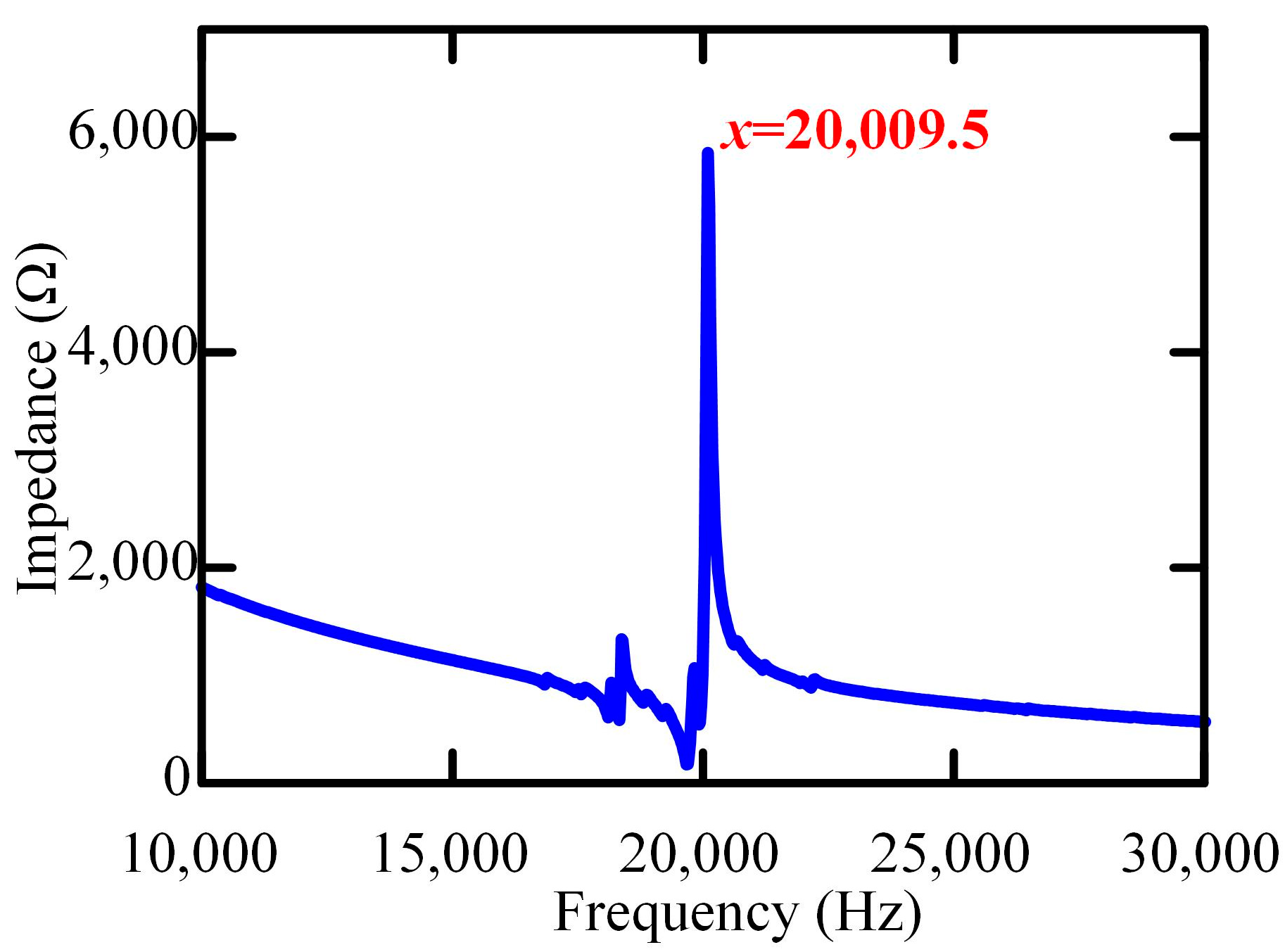
To determine the resonant frequency of the ultrasonic vibration platform under practical operating conditions, an impedance analysis experiment was performed using an impedance analyzer (WK6500B, Wayne Kerr, London, UK). During the experiment, the excitation voltage was set to 1 V, and the frequency sweep range was 10 kHz–30 kHz. The results are shown in Figure 4. They indicate that the resonant frequency of the ultrasonic vibration platform was 20,009.5 Hz. This value is very close to the simulated result of 19,939 Hz, verifying the reliability of the simulation findings. With consideration of the experimental error and other factors, the resonant frequency of the ultrasonic vibration platform was determined to be 20 kHz.
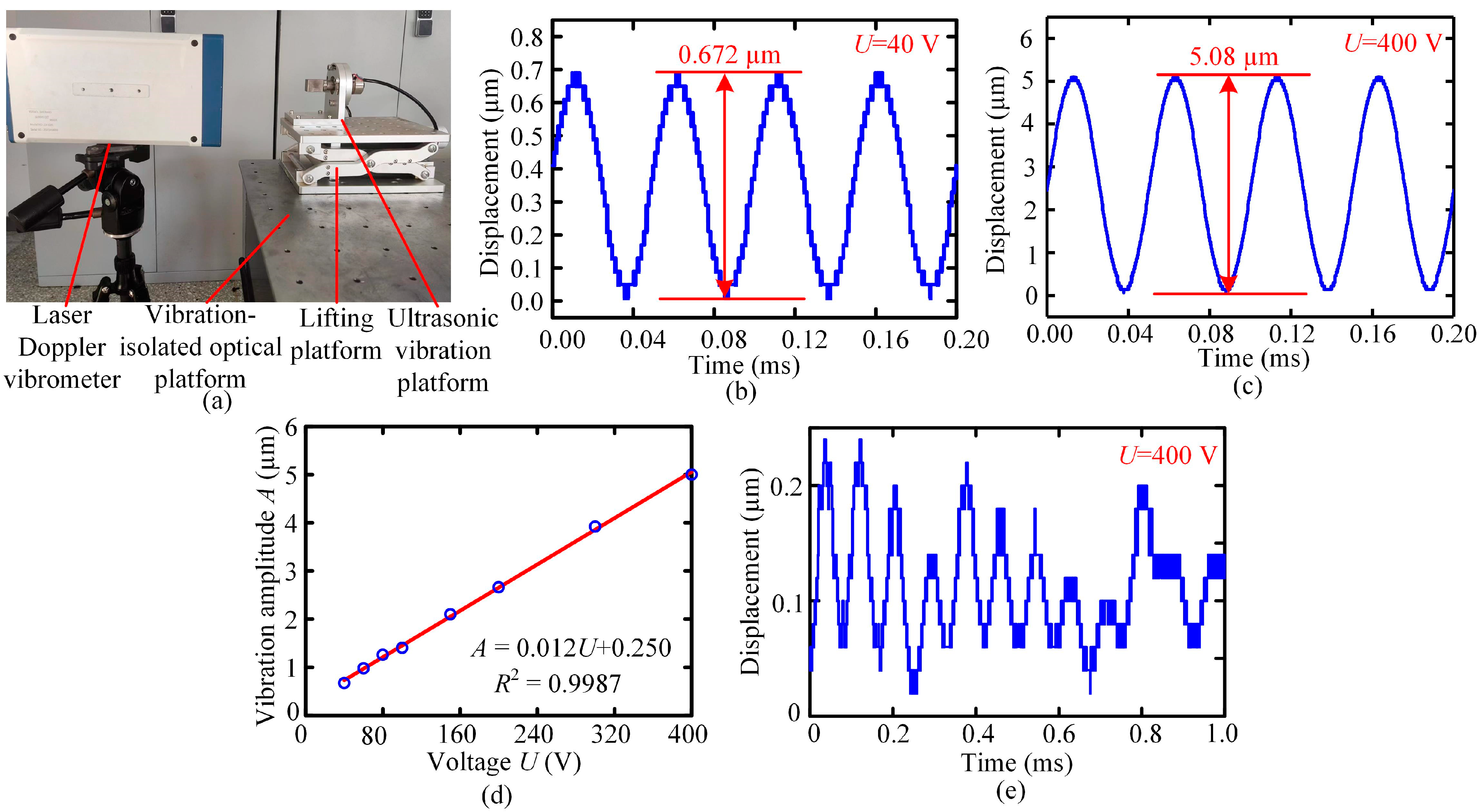
Furthermore, a laser Doppler vibrometer (LV-S20, SOPTOP, Nanjing, China), operating at a sampling frequency of 320 kHz, was employed to measure the performance of the ultrasonic vibration platform at a resonant frequency of 20 kHz, as shown in Figure 5a. The experimental setup consisted of a signal generator (DG4062, RIGOL Technologies, Suzhou, China), a power amplifier (HF-64, Nanjing Funeng Technology Industry Co., Ltd., Nanjing, China), an oscilloscope (DS1054Z, RIGOL Technologies, Suzhou, China), and the laser Doppler vibrometer. The signal generator produced a sinusoidal voltage signal with an amplitude of 5 V and a frequency of 20 kHz, and it was then amplified by the power amplifier to reach the operating voltages (40–400 V) of the ultrasonic transducer. The output displacements of the sample stage under various voltages (40, 60, 80, 100, 150, 200, 300, and 400 V) were measured by the laser Doppler vibrometer, and the measurement results were subsequently received and displayed by the oscilloscope. Taking the results obtained at 40 V and 400 V as examples, Figure 5b,c illustrate the output displacement changing with time, respectively. The results demonstrate that at both the minimum and maximum operating voltages of the ultrasonic transducer, the displacement curves exhibit a sinusoidal pattern with excellent periodic repeatability. Correspondingly, the ultrasonic vibration platform can provide stable vibration with the amplitude range of 0.672 µm to 5.08 µm. Figure 5d shows the vibration amplitude changing with the excitation voltage. By performing a linear regression analysis, the relationship between the excitation voltage U and the vibration amplitude A was obtained as:
A = 0.012U + 0.250.
And the corresponding linear correlation coefficient was 0.9987, demonstrating a good linear relationship between them. Figure 5e shows the displacement along the loading direction changing with time, obtained at the excitation voltage of 400 V. The results demonstrate that the amplitude was approximately 0.2 µm, which constitutes merely 4% of the amplitude in the scratch direction at the identical excitation voltage. Therefore, the amplitude in the loading direction had a negligible effect on the UVAS test.

3.2. UVAS Testing of AL1050

To verify the availability of the designed ultrasonic vibration scratch tester and to investigate the effect of ultrasonic vibration on the scratch characteristics of materials, scratch testing with and without ultrasonic vibration (i.e., UVAS test and CS test) were performed on the AL1050 sample. The samples were attached to the sample stage using paraffin wax, and during the scratch test, one edge of the Vickers indenter was forward. For comparison, various sinusoidal excitation voltages (40, 60, 80, and 100 V) at the same frequency of 20 kHz were applied to the ultrasonic vibration platform. According to Equation (1), the corresponding vibration amplitudes were calculated to be 0.73, 0.97, 1.21, and 1.45 μm, respectively. The scratch tests were conducted with a constant normal load of 500 mN, scratch length of 1000 μm, and scratch speed of 10 μm/s. After the tests, the morphologies of the residual scratch were examined using a scanning electron microscope (SEM, JSM-IT500A, JEOL, Tokyo, Japan), and the three-dimensional (3D) topographies were measured using a laser scanning confocal microscope (OLS5100, Olympus, Tokyo, Japan). Additionally, the content and distribution of elements on the surface of the residual scratch were analyzed using an energy dispersive spectroscope (EDS, EX-74600U4L2Q, JEOL, Tokyo, Japan).
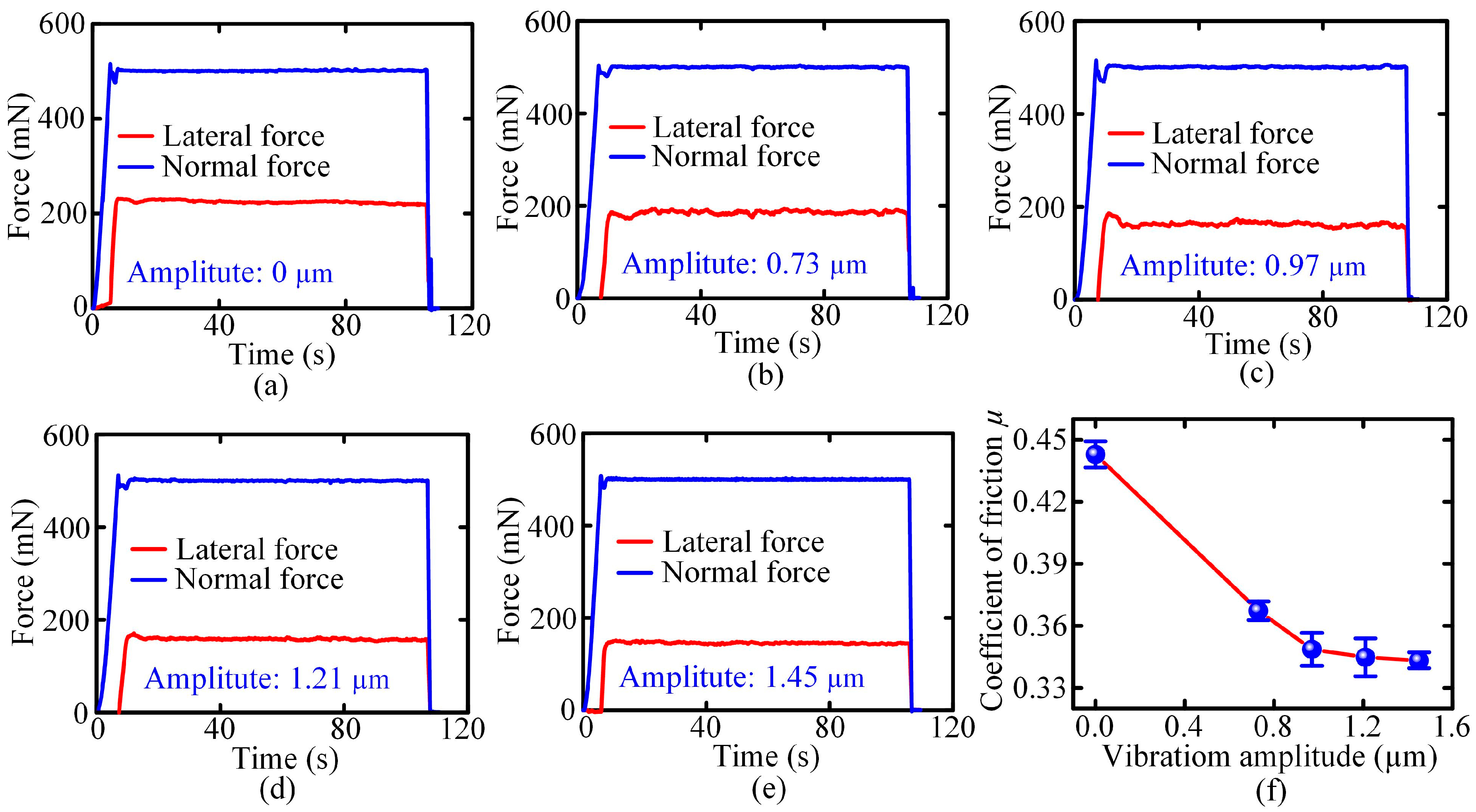
Figure 6a–e illustrate the normal force (perpendicular to the sample surface) and lateral force (parallel to the scratching direction) changing with time during the CS test (vibration amplitude: 0 μm) and UVAS test with different vibration amplitudes (0.73, 0.97, 1.21, and 1.45 μm), respectively. For all the curves, both the lateral force and normal force fluctuated around certain values, without significant variation during the stable stage. This was true for both the UVAS test and CS test. However, it is noted that the lateral force in the UVAS test was significantly lower than that in the CS test (around 220 mN) for all the employed vibration amplitudes. As the normal force was same for all the tests, it is confirmed that the introduction of ultrasonic vibration reduced the coefficient of friction during the scratch testing. Furthermore, the lateral force in the UVAS test with a vibration amplitude of 1.45 μm (around 170 mN) was significantly smaller than that with a vibration amplitude of 0.73 μm (around 185 mN), demonstrating that a relatively large vibration amplitude here was beneficial to reducing the coefficient of friction. The evolution of the coefficient of friction with the vibration amplitude is summarized in Figure 6f, which shows an evident decreasing tendency with the increase in the vibration amplitude.
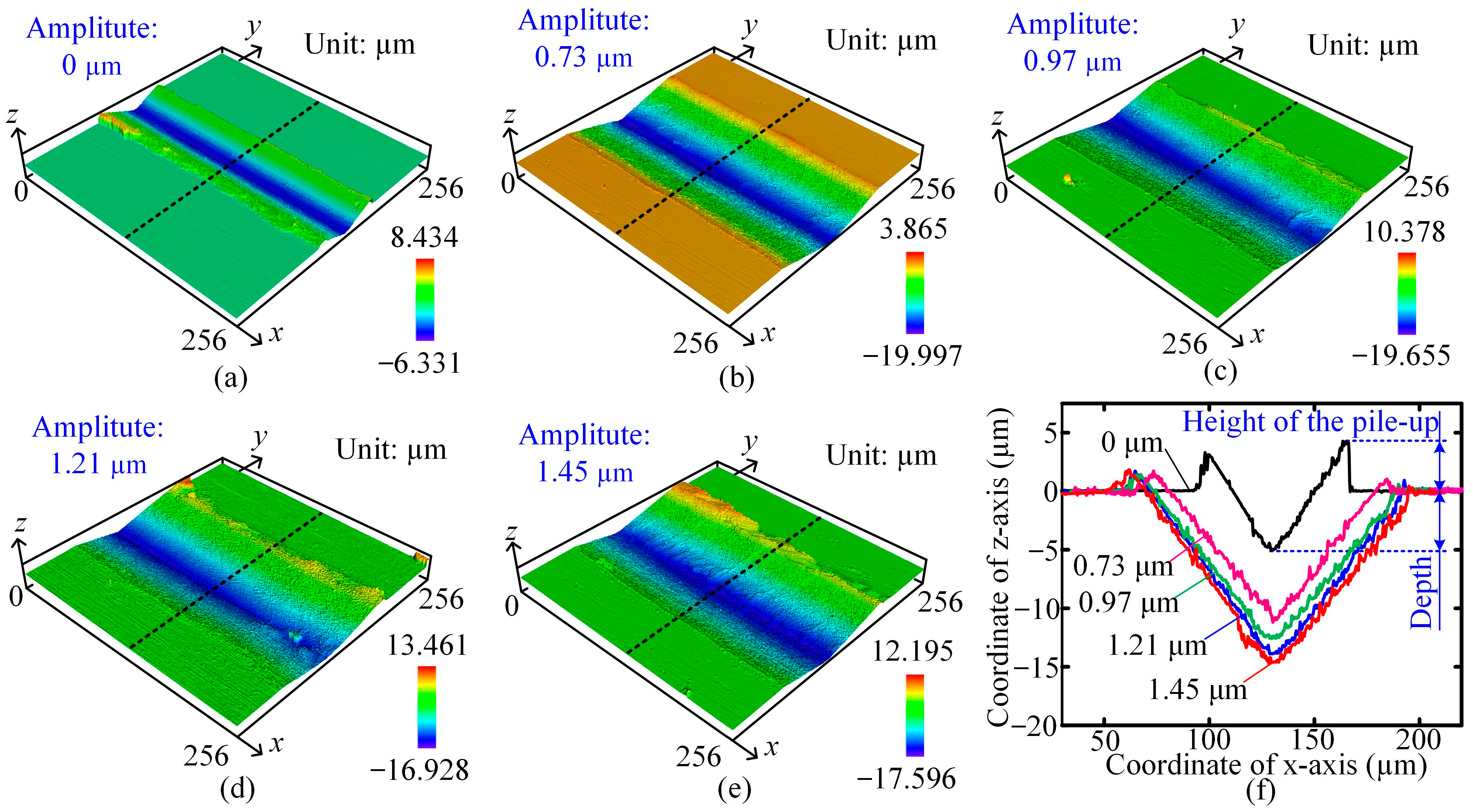
Figure 7a–e show the corresponding 3D topographies of the residual scratch, and Figure 7f illustrates the profiles of the cross-sections marked in Figure 7a–e. In Figure 7a, after the CS test, a V-groove was generated on the surface, with evident pile-ups around. This could be further confirmed from the cross-sectional profile. The depth of the V-groove was about 5.11 μm, and the height of the pile-up was about 4.23 μm. Compared to the residual scratch obtained in the CS test, the size of the residual scratch was significantly increased in the UVAS test, and the whole size also depended on the vibration amplitude. As shown in Figure 7f, the depth of the residual scratch was significantly increased from 5.11 μm in the CS test to 12.44 μm in the UVAS test with the vibration amplitude of 0.73 μm. When further increasing the vibration amplitude, the depth of the residual scratch tended to increase, and when the vibration amplitude reached 1.45 μm, the depth of the residual scratch was about 14.93 μm, which is significantly larger than that in the CS test. The principal factor contributing to the augmented depth of the residual scratch during the UVAS test was the intensified relative motion between the indenter and the material, with the influence of vibration. The enhanced relative movement allowed for the comprehensive removal of material from the scratched area, thus increasing the scratch depth [24]. However, even with a remarkable increase in the depth of the residual scratch, the corresponding pile-ups around the V-groove were greatly reduced. For example, when the vibration amplitude was 0.73 μm, the corresponding height of the pile-up was around 1 μm; with the increase in vibration amplitude, the height of the pile-up had no significant difference.
As shown in Figure 8, being the same as the 3D topographies, the SEM morphologies of the residual scratches in the UVAS test also show some significant differences compared to those in the CS test. In Figure 8a, there are many fine scratches on the inner surface of the residual scratch obtained during the CS test. Combined with the 3D topography in Figure 7a, it is derived that the removal mechanism of AL1050 during the CS test was mainly dominated by plowing [27]. Instead of the fine scratches obtained in the CS test, wrinkles were formed on the inner surface of the residual scratches in the UVAS test, as shown in Figure 8b–e. This indicates a transformation in the material removal mechanism from plowing to cutting [27], which resulted in the reduction in pile-ups around the V-groove. The contact between the indenter and the material was altered by the repeated back-and-forth relative movement caused by ultrasonic vibration, resulting in the generation of wrinkles. Nevertheless, the surface quality of the residual scratch obtained by UVAS testing at different vibration amplitudes did not differ significantly, which is also confirmed by Figure 7a. As the vibration amplitude increased, the relative movement between the indenter and the material also increased, resulting in more pronounced wrinkles on the inner surface of the residual scratch, as shown in Figure 8b–e.
The above observations, on the one hand, serve as evidence that the ultrasonic vibration scratch tester has the ability to perform scratch testing under ultrasonic vibration contact status. On the other hand, these phenomena demonstrate that the application of ultrasonic vibration and the amplitude of such a vibration significantly affect both the coefficient of friction and the material removal rate. As the vibration amplitude increased, there was a decrease in the coefficient of friction and an increase in the depth of the residual scratch. Compared to the CS test, the coefficient of friction decreased by about 22.5%, while the depth of the residual scratch increased by about 175% under ultrasonic vibration with a vibration amplitude of 1.45 μm and a frequency of 20 kHz. Compared to the UVAS test with a vibration amplitude of 0.73 μm, the UVAS test with a vibration amplitude of 1.45 μm exhibited a 6.55% reduction in the coefficient of friction and a 19% increase in the depth of the residual scratch. These phenomena are consistent with some previous studies [25,28]. However, the variations in the coefficient of friction and the depth of the residual scratch with the vibration amplitude were relatively large at small vibration amplitudes and decreased as the vibration amplitude increased. This could be due to the oxidizing effect during the UVAS test [29,30].
In order to investigate the reason for the diminished growth rates of the coefficient of friction and the depth of the residual scratch with the increased vibration amplitude, the content of oxygen and its distribution on the surface of the residual scratch were measured by an energy spectrometer. Figure 9a–e illustrate the distribution of oxygen on the residual scratch of AL1050 under different vibration amplitudes. Figure 9f provides the relationship between the percentage of oxygen and the vibration amplitude. The residual scratch surface after the CS test had a uniform distribution of oxygen, and the oxygen content was notably low. However, as the vibration amplitude increased, the oxygen content significantly increased and was predominantly concentrated on the inner surface of the residual scratch. The percentage of oxygen increased from 2.68 ± 0.05% in the CS test to 14.48 ± 0.05% in the UVAS test with an amplitude of 1.45 μm, which indicates that severe oxidation occurred on the AL1050 sample during the UVAS test. This oxidation was likely caused by the repeated frictional heating between the indenter and the sample during the UVAS test, promoting the oxidation reaction. The formation of aluminum oxide can lead to an increase in material hardness, making it more difficult to remove material during the subsequent scratch process. Therefore, the hardening process resulting from increased oxidation due to large vibration amplitudes may have reduced the effect of ultrasonic vibration on decreasing the coefficient of friction and increasing the scratch depth. This also highlights the importance of selecting an appropriate amplitude during ultrasonic vibration-assisted machining.

4. Conclusions

In summary, an ultrasonic vibration scratch tester for characterizing the scratch characteristics of materials under ultrasonic vibration contact status was developed. By analysis and experiments, the following conclusions were obtained.
(1)
The ultrasonic vibration platform could generate stable ultrasonic vibration at a frequency of 20 kHz within the amplitude range from 0.73 µm to 5.08 µm. The vibration amplitude had a good linear relationship with the excitation voltage.
(2)
The ultrasonic vibration scratch tester could perform ultrasonic vibration-assisted scratch (UVAS) testing of materials and simultaneously measure the normal force and lateral force.
(3)
Comparative experiments of AL1050 indicate that compared to conventional scratch (CS) testing, the introduction of ultrasonic vibration reduced the coefficient of friction, increased the depth of the residual scratch, and significantly reduced the height of the pile-up. These kinds of effects were dependent on the vibration amplitude. For the vibration amplitude of 1.45 μm, the coefficient of friction decreased by approximately 22.5%, and the depth of the residual scratch increased by approximately 175%.
(4)
SEM morphologies showed different material removal mechanisms of AL1050, plowing in the CS test, and cutting in the UVAS test. In addition, oxidation of the AL1050 occurred in the UVAS test, contributing to the different scratch characteristics listed above.

Author Contributions

Conceptualization, H.H.; methodology, Y.H. and H.W.; software, H.W.; validation, Y.H., Y.Y., and H.W.; investigation, Y.H., Y.Y., and H.W.; resources, H.H.; writing—original draft preparation, Y.H., Y.Y., and H.W.; writing—review and editing, H.H.; visualization, Y.H., Y.Y., and H.W.; supervision, H.H. and H.Z.; project administration, H.H.; funding acquisition, H.H. All authors have read and agreed to the published version of the manuscript.

Funding

This research was funded by the Jilin Province Key Research and Development Plan Project (20240302066GX), the National Natural Science Foundation of China (Grant No. 52075221), and the Fundamental Research Funds for the Central Universities (2023-JCXK-02).

Data Availability Statement

The data that support the findings of this study are available on request from the corresponding author [Hu Huang].

Conflicts of Interest

The authors declare no conflicts of interest.

References

  1. Azarhoushang, B.; Tawakoli, T. Development of a novel ultrasonic unit for grinding of ceramic matrix composites. Int. J. Adv. Manuf. Technol. 2011, 57, 945–955. [Google Scholar] [CrossRef]
  2. Nath, C.; Rahman, M. Effect of machining parameters in ultrasonic vibration cutting. Int. J. Mach. Tools Manuf. 2008, 48, 965–974. [Google Scholar] [CrossRef]
  3. Babitsky, V.I.; Mitrofanov, A.V.; Silberschmidt, V.V. Ultrasonically assisted turning of aviation materials: Simulations and experimental study. Ultrasonics 2004, 48, 81–86. [Google Scholar] [CrossRef] [PubMed]
  4. Teimouri, R.; Amini, S.; Lotfi, M.; Alinaghian, M. Sustainable drilling process of 1045 steel plates regarding minimum energy consumption and desired work quality. Int. J. Lightweight Mater. Manuf. 2019, 25, 397–406. [Google Scholar] [CrossRef]
  5. Yang, Z.; Zou, P.; Zhou, L.; Wang, X. Research on modeling of grinding force in ultrasonic vibration–assisted grinding of 304 stainless steel materials. Int. J. Adv. Manuf. Technol. 2022, 120, 3201–3223. [Google Scholar] [CrossRef]
  6. Duan, J.; Zou, P.; Wei, S.; Fang, R.; Fang, L. Research on the formation mechanism of surface morphology in three-excitation ultrasonic spatial vibration-assisted turning. Int. J. Adv. Manuf. Technol. 2022, 121, 6851–6876. [Google Scholar] [CrossRef]
  7. Zhao, B.; Wu, B.; Yue, Y.; Ding, W.; Xu, J.; Guo, G. Developing a novel radial ultrasonic vibration-assisted grinding device and evaluating its performance in machining PTMCs. Chin. J. Aeronaut. 2023, 36, 244–256. [Google Scholar] [CrossRef]
  8. Li, S.; Xiao, G.; Chen, B.; Zhuo, X.; Xu, J.; Huang, Y. Surface formation modeling and surface integrity research of normal ultrasonic assisted flexible abrasive belt grinding. J. Manuf. Process. 2022, 80, 232–246. [Google Scholar] [CrossRef]
  9. Liu, Y.; Geng, D.; Zhang, D.; Zhai, Y.; Liu, L.; Sun, Z.; Shao, Z.; Zhang, M.; Jiang, X. Cutting performance and surface integrity for rotary ultrasonic elliptical milling of Inconel 718 with the ball end milling cutter. J. Mater. Process. Technol. 2023, 319, 118094. [Google Scholar] [CrossRef]
  10. Pujana, J.; Rivero, A.; Celaya, A.; López de Lacalle, L.N. Analysis of ultrasonic-assisted drilling of Ti6Al4V. Int. J. Mach. Tools Manuf. 2009, 49, 500–508. [Google Scholar] [CrossRef]
  11. Celaya, A.; Campa, F.J.; López de Lacalle, L.N.; Marina, D.; Chinesta, F.; Chastel, Y.; El Mansori, M. The Effects of Ultrasonic Vibration Parameters on Machining Performance in Turning of Mild Steels. Int. Conf. Adv. Mater. Process. Technol. 2011, 1315, 1139–1144. [Google Scholar]
  12. Celaya, A.; López de Lacalle, L.N.; Campa, F.J.; Lamikiz, A. Ultrasonic assisted turning of mild steels. Int. J. Mater. Prod. Technol. 2010, 37, 60–70. [Google Scholar] [CrossRef]
  13. Suárez, A.; Veiga, F.; de Lacalle, L.N.L.; Polvorosa, R.; Lutze, S.; Wretland, A. Effects of Ultrasonics-Assisted Face Milling on Surface Integrity and Fatigue Life of Ni-Alloy 718. J. Mater. Eng. Perform. 2016, 2, 5076–5086. [Google Scholar] [CrossRef]
  14. He, G.; Wu, H.; Huang, H.; Zhao, H. An in-situ scratch tester under the confocal laser scanning microscope (CLSM). Vacuum 2024, 222, 113033. [Google Scholar] [CrossRef]
  15. Domagała, I.; Gil, L.; Firlej, M.; Pieniak, D.; Selech, J.; Romek, D.; Biedziak, B. Statistical Comparison of the Hardness and Scratch-Resistance of the PMMA Polymers Used in Orthodontic Appliances. Adv. Sci. Technol. Res. J. 2020, 14, 250–261. [Google Scholar] [CrossRef]
  16. Kamplade, K.; Biermann, D. Examination of the Material Removal of unreinforced, thermoplastic Polymers by Scratch Tests. Prod. Eng. 2019, 13, 713–719. [Google Scholar] [CrossRef]
  17. Tang, J.; Wei, J.; Wang, Y.; Xu, Z.; Huang, H. A Novel Rotation-Structure Based Stick-Slip Piezoelectric Actuator with High Consistency in Forward and Reverse Motions. Actuators 2021, 10, 189. [Google Scholar] [CrossRef]
  18. Yang, X.; Tang, J.; Guo, W.; Huang, H.; Fan, H.; Liu, J.; Li, T. Design and Analysis of a Stepping Piezoelectric Actuator Free of Backward Motion. Actuators 2021, 10, 200. [Google Scholar] [CrossRef]
  19. Ji, M.; Xu, J.; Li, L.; Yu, D.; Chen, M.; Geier, N.; El Mansori, M. Investigation of material removal mechanisms and ductile-brittle transition zone of zirconia ceramics sintered at various temperatures. J. Mech. Behav. Biomed. Mater. 2022, 125, 104944. [Google Scholar] [CrossRef] [PubMed]
  20. Zeng, K.; Wu, X.; Jiang, F.; Fang, C.; Zhu, L.; Zhang, J.; Wang, M.; Liu, C. Material removal and surface damage mechanisms in micro drilling of Nd:YAG material. J. Manuf. Process. 2023, 90, 43–53. [Google Scholar] [CrossRef]
  21. Li, C.; Piao, Y.; Meng, B.; Zhang, Y.; Li, L.; Zhang, F. Anisotropy dependence of material removal and deformation mechanisms during nanoscratch of gallium nitride single crystals on (0001) plane. Appl. Surf. Sci. 2022, 578, 152028. [Google Scholar] [CrossRef]
  22. Huang, W.; Yan, J. Deformation behaviour of soft-brittle polycrystalline materials determined by nanoscratching with a sharp indenter. Precis. Eng. 2021, 72, 717–729. [Google Scholar] [CrossRef]
  23. Cao, S.; Zhang, X.; Wu, C.; Yang, M.; Xia, K. Towards understanding the material removal mechanism on the effect of ultrasonic vibration and anisotropy for unidirectional CFRP by scratching. J. Mater. Process. Technol. 2024, 324, 118250. [Google Scholar] [CrossRef]
  24. Zhou, W.; Tang, J.; Li, Z.; Shao, W.; Wen, J.; Huang, W. Study on scratch hardness in ultrasonic vibration-assisted scratching based on instantaneous contact analysis. Wear 2023, 528–529, 204991. [Google Scholar] [CrossRef]
  25. Zheng, F.; Dong, Z.; Kang, R.; Zhang, B.; Zhu, X.; Liu, J. Analysis of material removal behavior in ultrasonically assisted scratching of RB-SiC from energy aspects. Int. J. Adv. Manuf. Technol. 2018, 98, 2257–2270. [Google Scholar] [CrossRef]
  26. Wu, H.; Huang, H.; Xu, Z.; Li, X.; Zhao, H. Development of a Vibration-Assisted Micro/Nano Scratch Tester for Evaluating the Scratch Behaviors of Materials Under Vibration Environment. IEEE Trans. Ind. Electron. 2024, 1–10. [Google Scholar] [CrossRef]
  27. Tao, H.; Liu, Y.; Zhao, D.; Lu, X. Prediction and measurement for grinding force in wafer self-rotational grinding. Int. J. Mech. Sci. 2023, 258, 108530. [Google Scholar] [CrossRef]
  28. Lin, W.; Hu, Z.; Chen, Y.; Zhang, Y.; Yu, Y.; Xu, X.; Zhang, J. Comparison of Vibration-Assisted Scratch Characteristics of SiC Polytypes (3C-, 4H- and 6H-SiC). Micromachines 2022, 13, 640. [Google Scholar] [CrossRef] [PubMed]
  29. Wang, S.Y.; Yang, W.J.; Ma, L.L. Advances in Theoretical Investigation of Work Hardening for Metal Cutting. Appl. Mech. Mater. 2012, 217–219, 2060–2064. [Google Scholar] [CrossRef]
  30. Dai, S.J.; Wen, D.H.; Yuan, J.L. PCBN Tool Wear Mechanism in Hard Turning Hardened Bearing Steel. Key Eng. Mater. 2006, 315–316, 334–338. [Google Scholar] [CrossRef]
Figure 1. Frequency characteristics of the sample stage with different dimensions obtained by FE simulation: (a) 20 mm × 20 mm × 23 mm; (b) 20 mm × 20 mm × 24 mm; (c) 20 mm × 20 mm × 25 mm; (d) 20 mm × 20 mm × 26 mm; (e) 20 mm × 20 mm × 27 mm; (f) 20 mm × 20 mm × 28 mm.
Actuators 13 00262 g001
Figure 2. Three-dimensional model of the designed ultrasonic vibration platform.
Actuators 13 00262 g002
Figure 3. Prototype of the ultrasonic vibration scratch tester.
Actuators 13 00262 g003
Figure 4. Impedance characteristic of the ultrasonic vibration platform.
Actuators 13 00262 g004
Figure 5. (a) Vibration amplitude measurement of the ultrasonic vibration platform using the laser Doppler vibrometer. (b) Output displacement changing with time, obtained at the excitation voltage of 40 V. (c) Output displacement changing with time, obtained at the excitation voltage of 400 V. (d) Relationship between the excitation voltage and the vibration amplitude. (e) Displacement along the loading direction changing with time obtained at the excitation voltage of 400 V.
Actuators 13 00262 g005
Figure 6. (ae) Curves of lateral and normal forces of (a) CS test and (be) UVAS test under different vibration amplitudes: (b) 0.73 μm; (c) 0.97 μm; (d) 1.21 μm; (e) 1.45 μm. (f) Summary of the coefficient of friction changing with the vibration amplitude.
Actuators 13 00262 g006
Figure 7. (ae) Three-dimensional topographies of the residual scratch on the AL1050 surface obtained by (a) CS testing and (be) UVAS testing under different vibration amplitudes: (b) 0.73 μm; (c) 0.97 μm; (d) 1.21 μm; (e) 1.45 μm. (f) Profiles of the cross-sections marked in (ae).
Actuators 13 00262 g007
Figure 8. (ae) SEM morphologies of the residual scratches on the AL1050 surface obtained by (a) CS testing and (be) UVAS testing under different vibration amplitudes: (b) 0.73 μm; (c) 0.97 μm; (d) 1.21 μm; (e) 1.45 μm.
Actuators 13 00262 g008
Figure 9. (ae) Distribution of oxygen on the residual scratches of AL1050 under different vibration amplitudes: (a) 0 μm; (b) 0.73 μm; (c) 0.97 μm; (d) 1.21 μm; (e) 1.45 μm. The color red indicates the presence of oxygen. (f) Effect of the vibration amplitude on percentage of oxygen on the residual scratch surface.
Actuators 13 00262 g009
Disclaimer/Publisher’s Note: The statements, opinions and data contained in all publications are solely those of the individual author(s) and contributor(s) and not of MDPI and/or the editor(s). MDPI and/or the editor(s) disclaim responsibility for any injury to people or property resulting from any ideas, methods, instructions or products referred to in the content.