
Increasing Payload Capacity of a Continuum Soft Robot Using Bio-Inspired Ossicle Reinforcement

Abstract
:1. Introduction
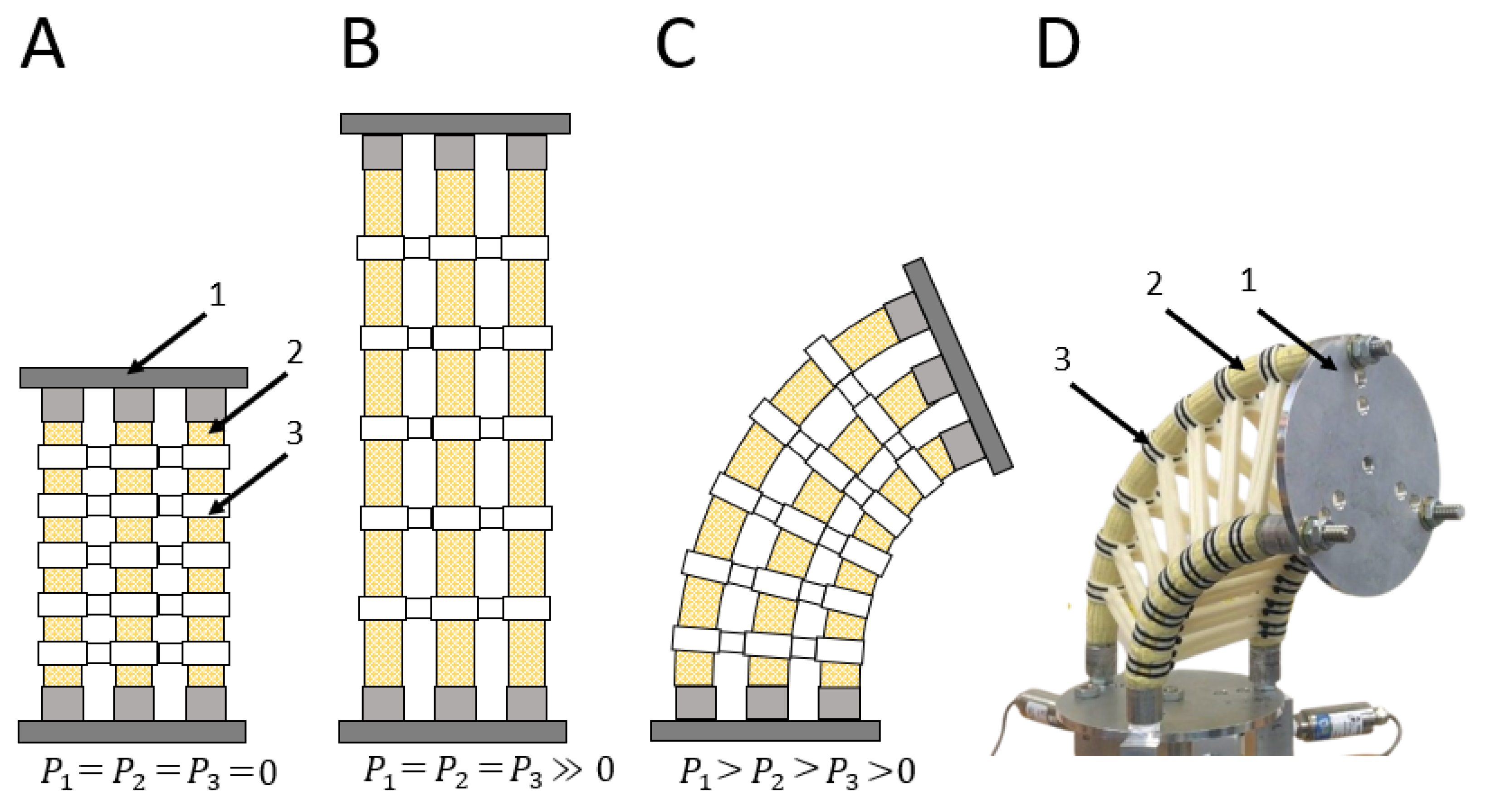
Initial Observations
2. Materials and Methods
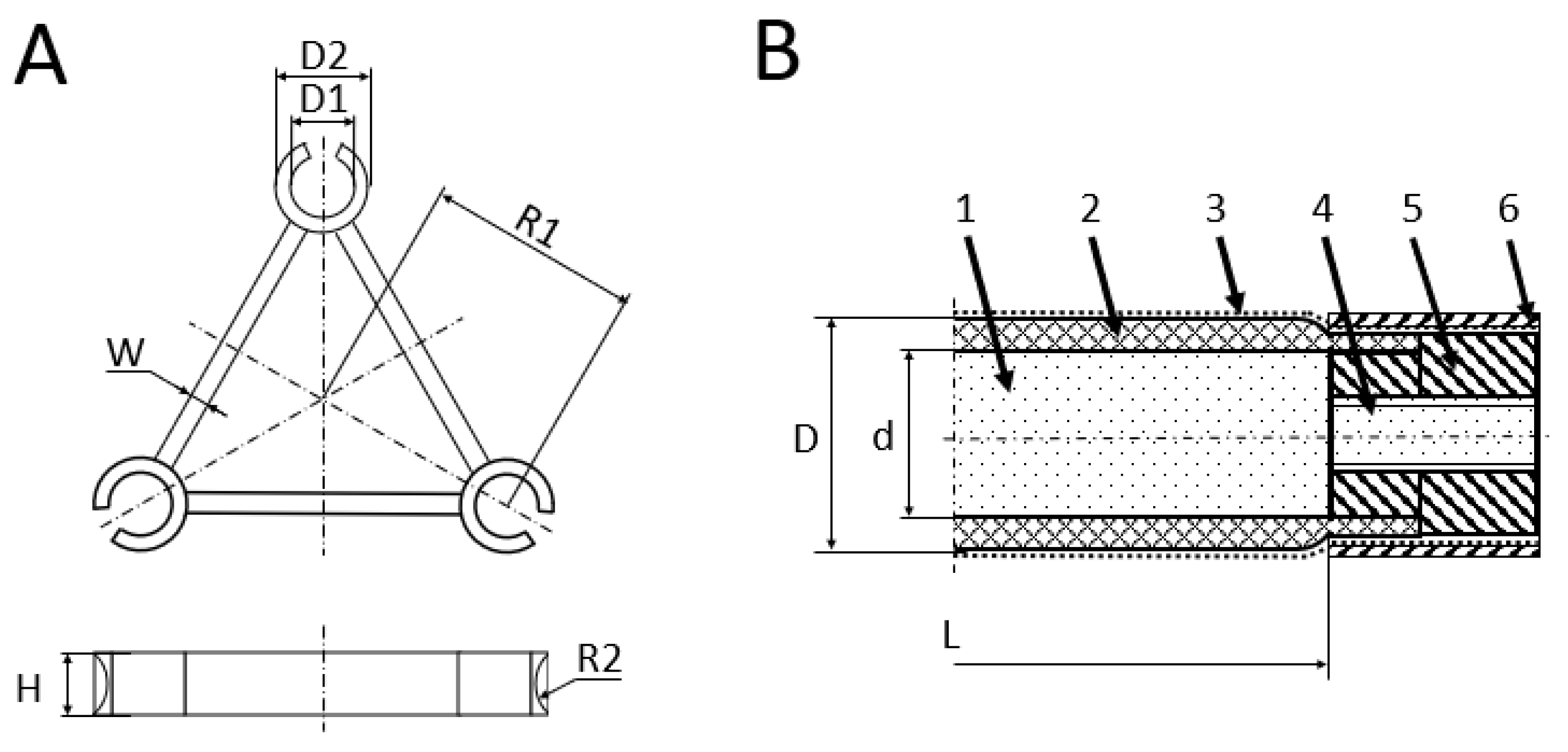
2.1. Materials
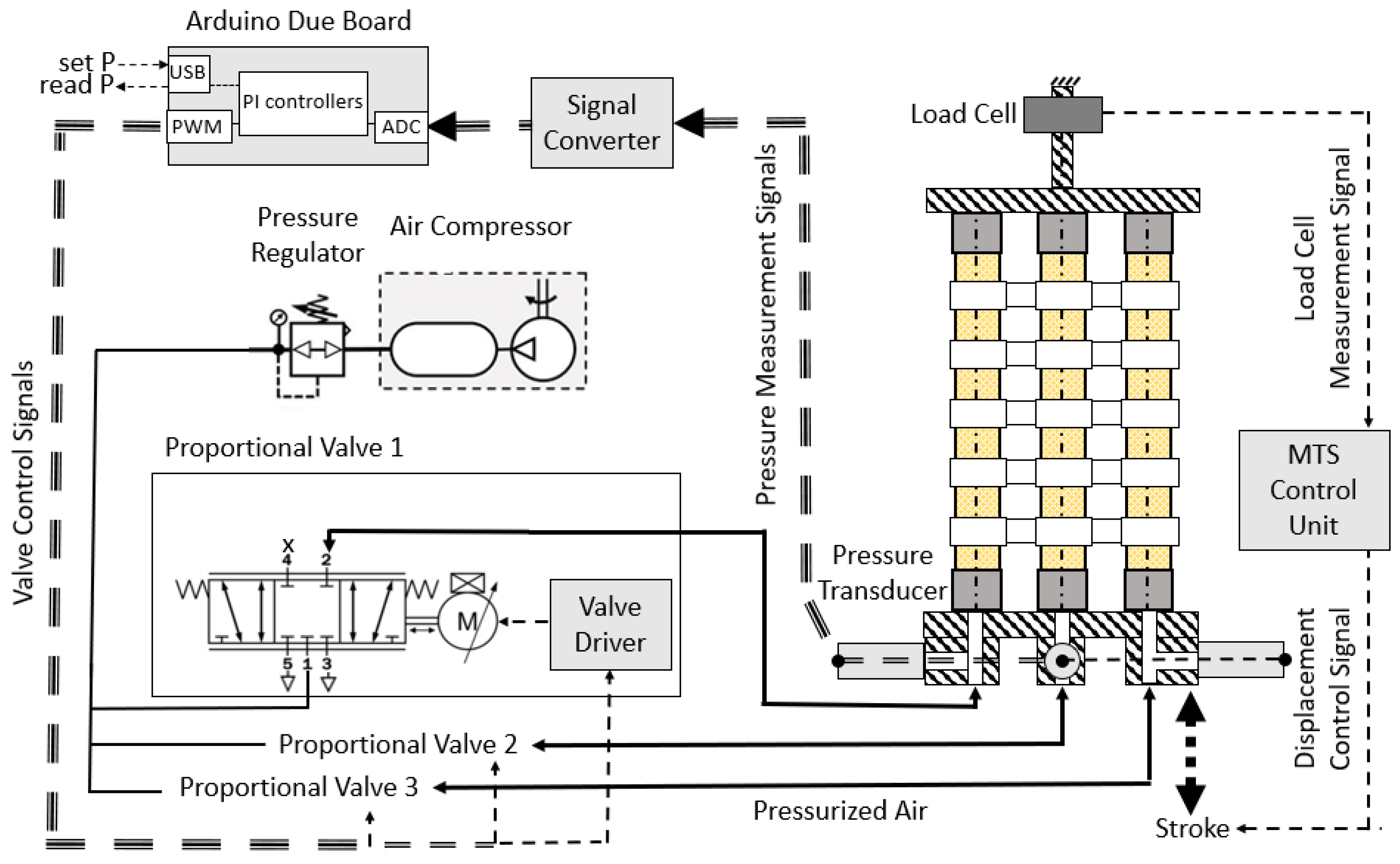
2.2. Methods
3. Experimental Results
3.1. Maximum Non-Buckling Pressure
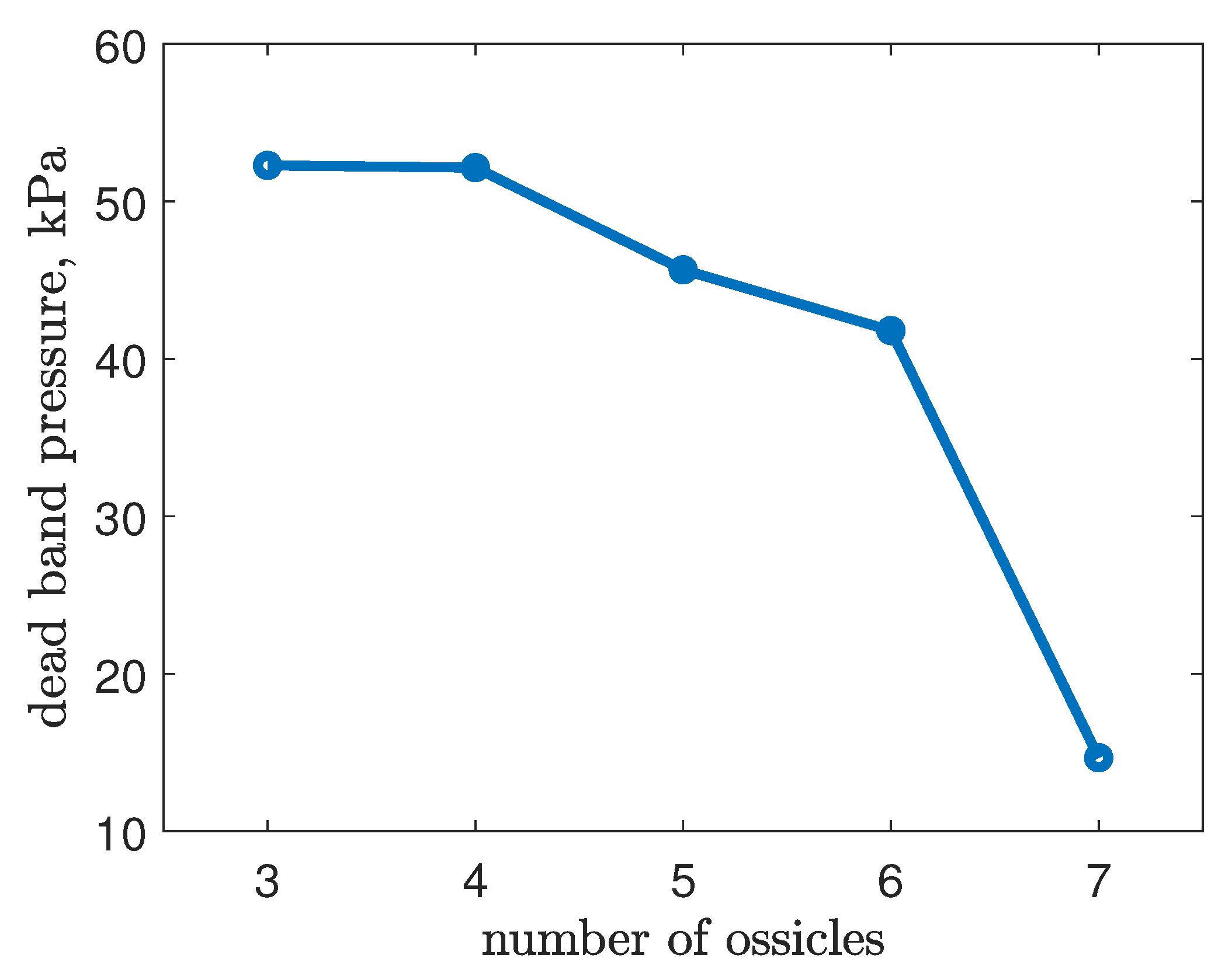
3.2. Dead-Band Pressure
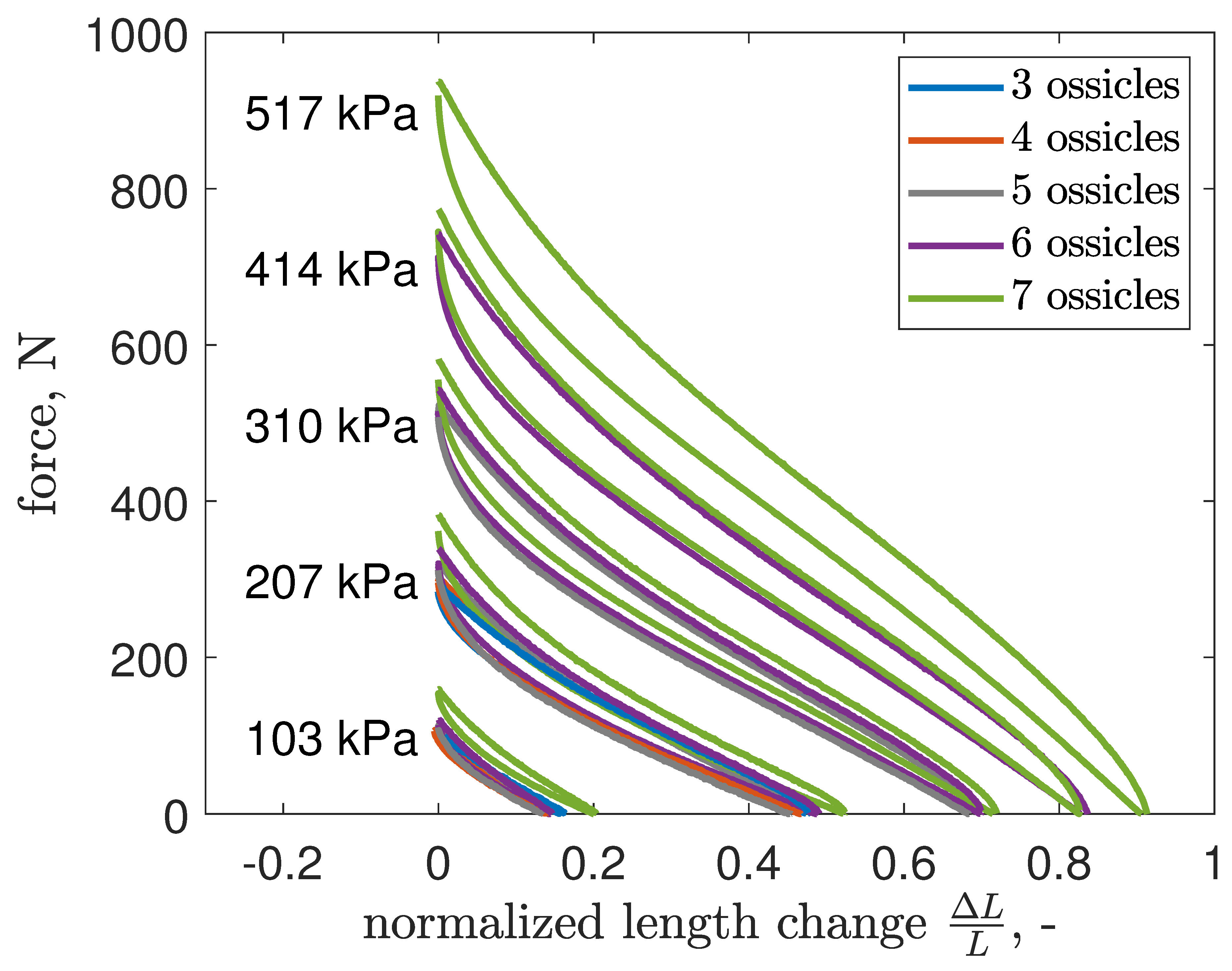
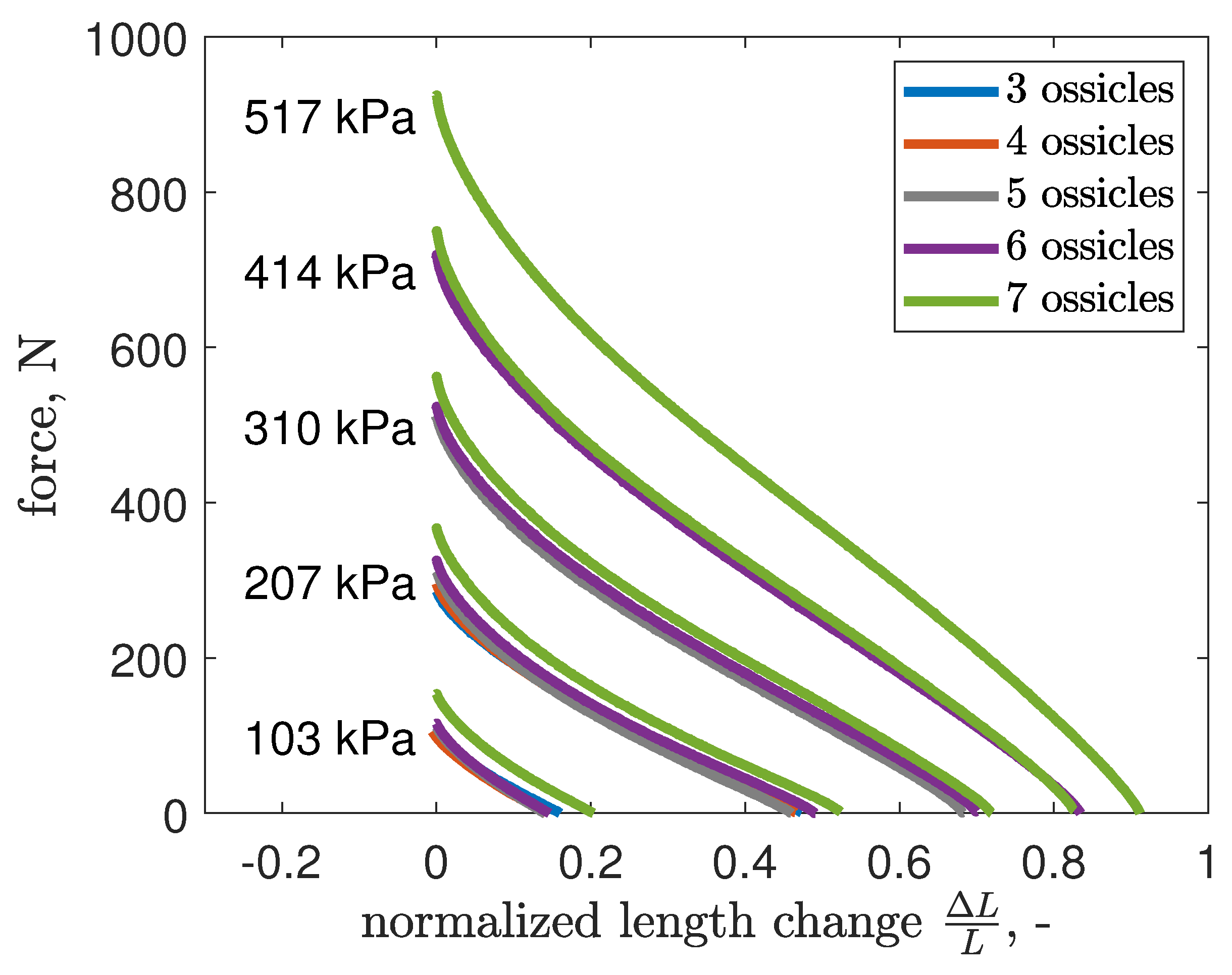
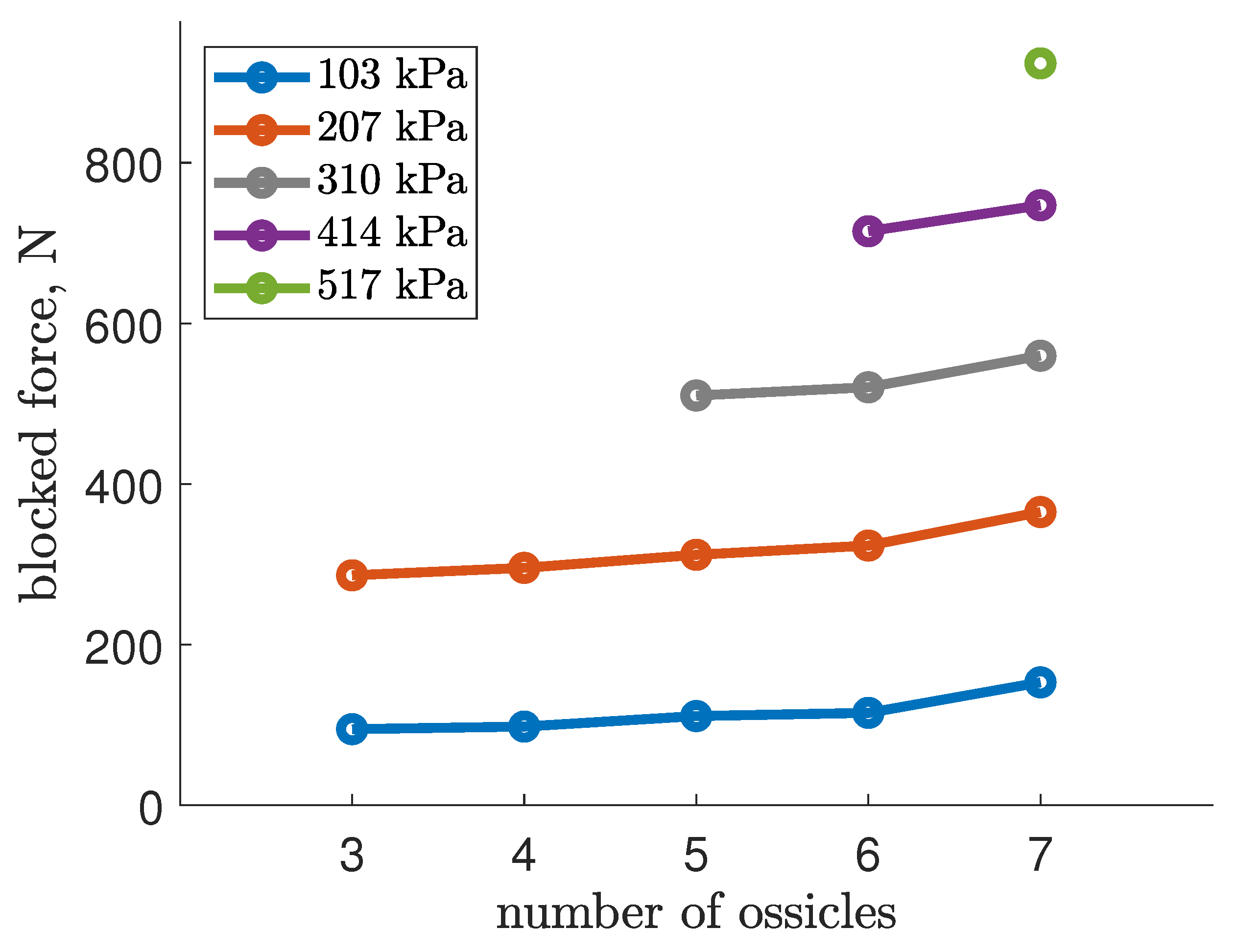
3.3. Blocked Force
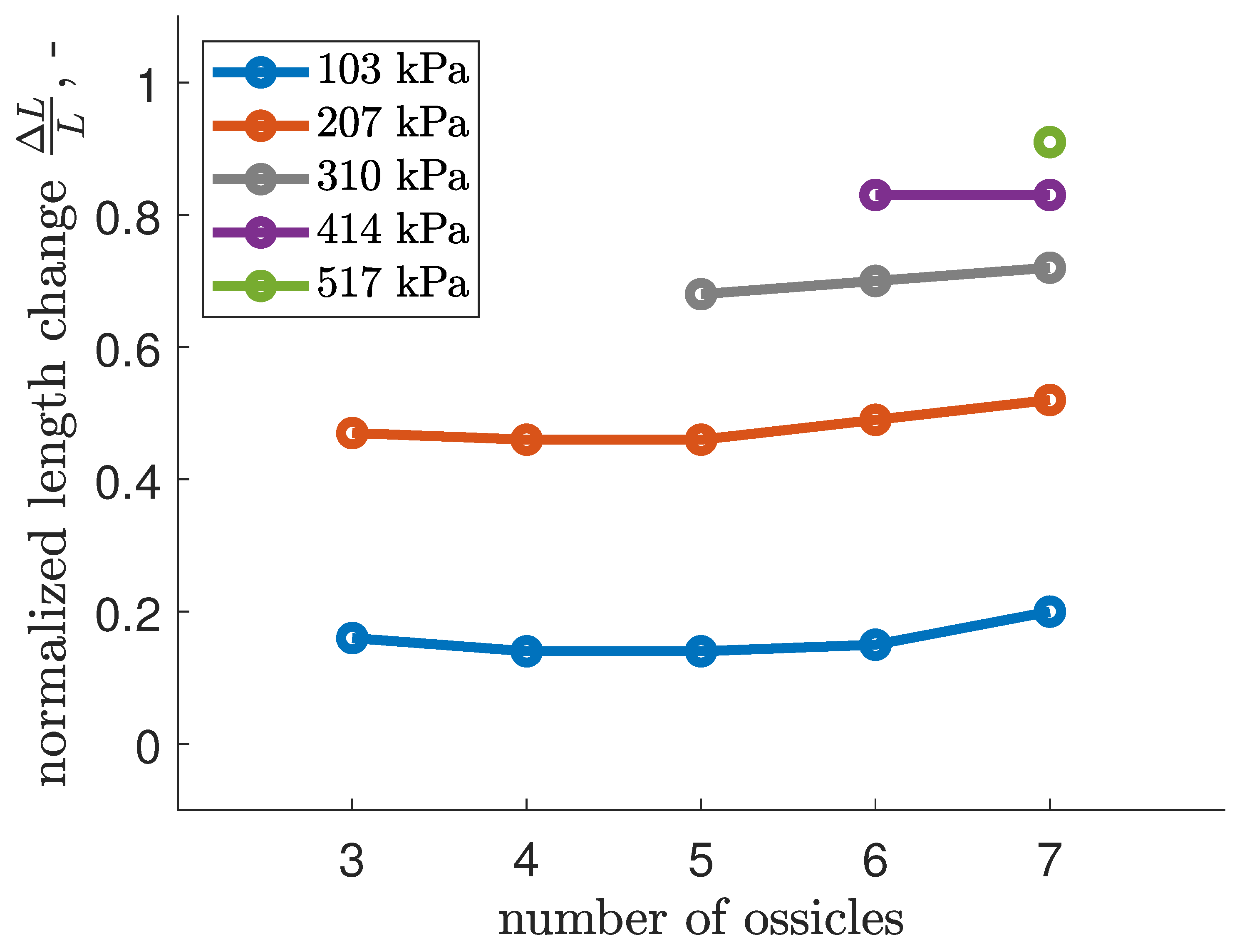
3.4. Free Extension
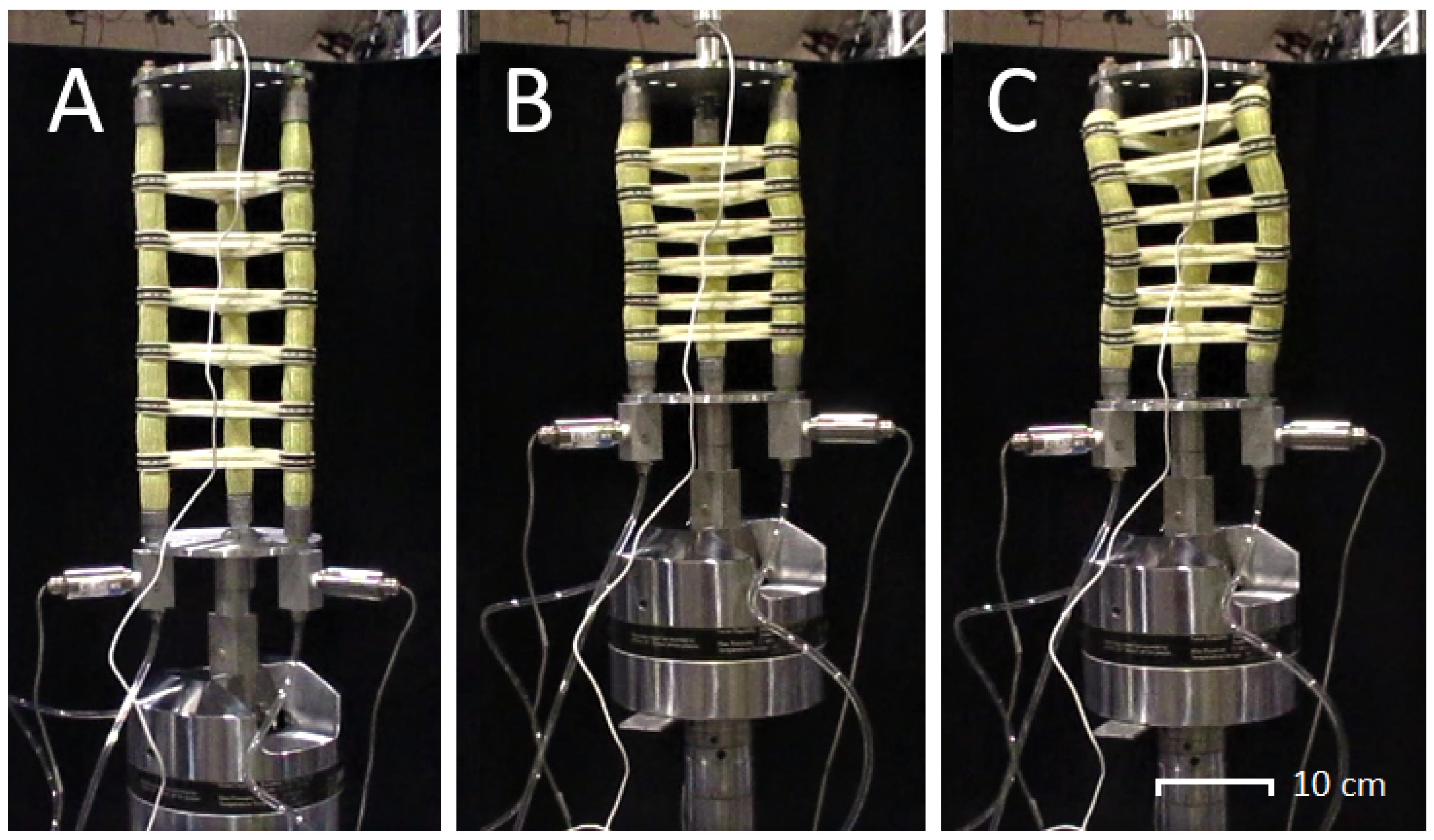
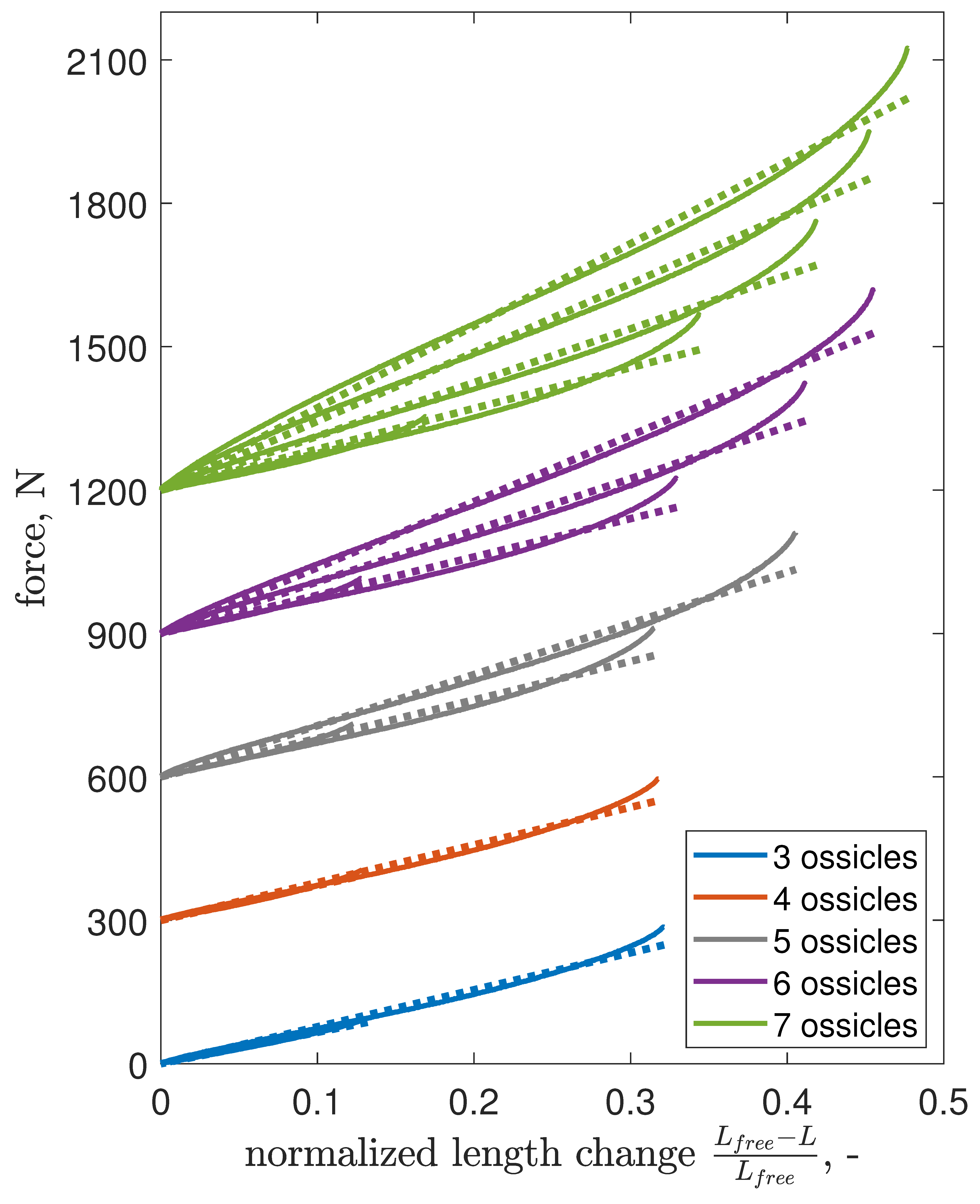
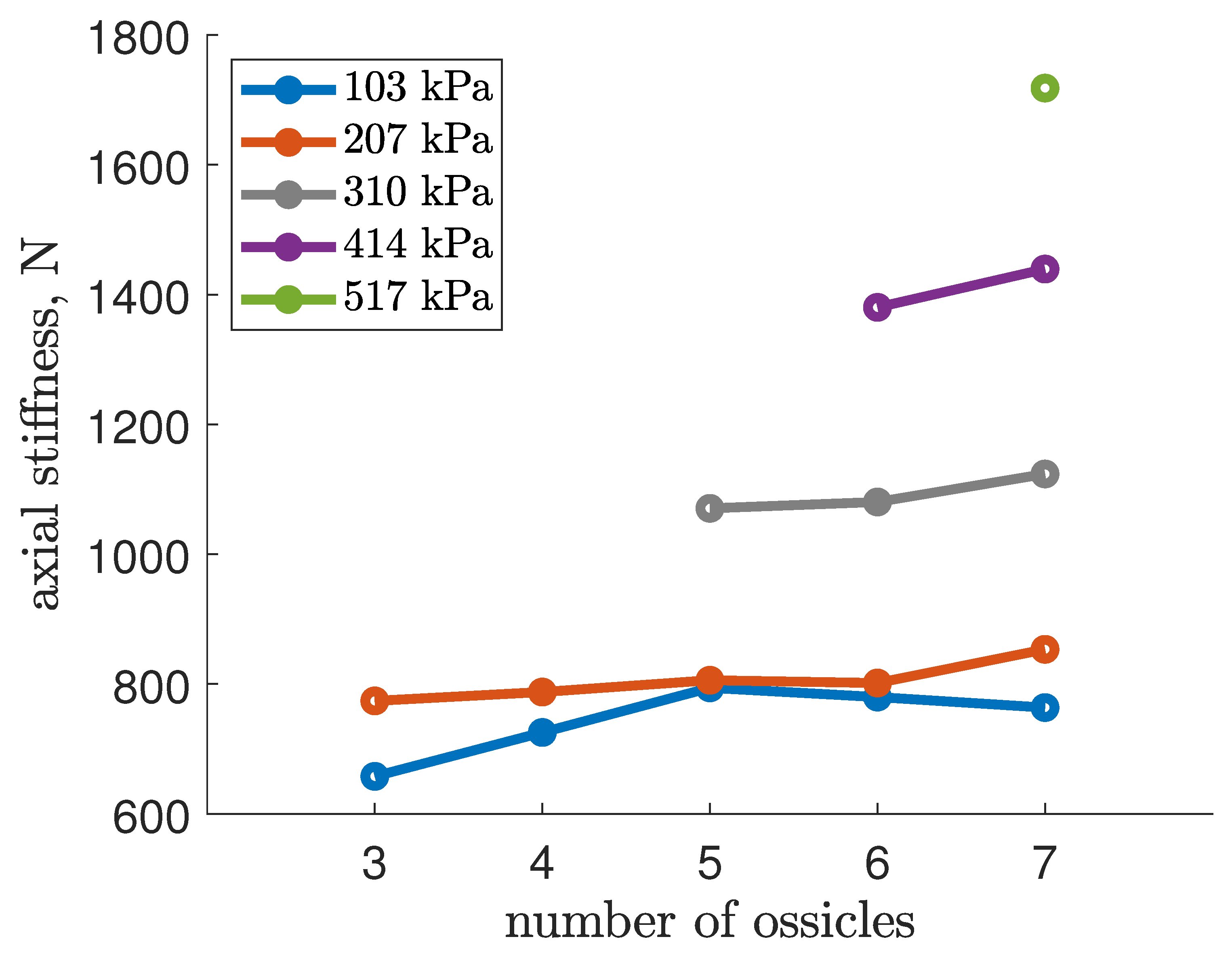
3.5. Axial Stiffness
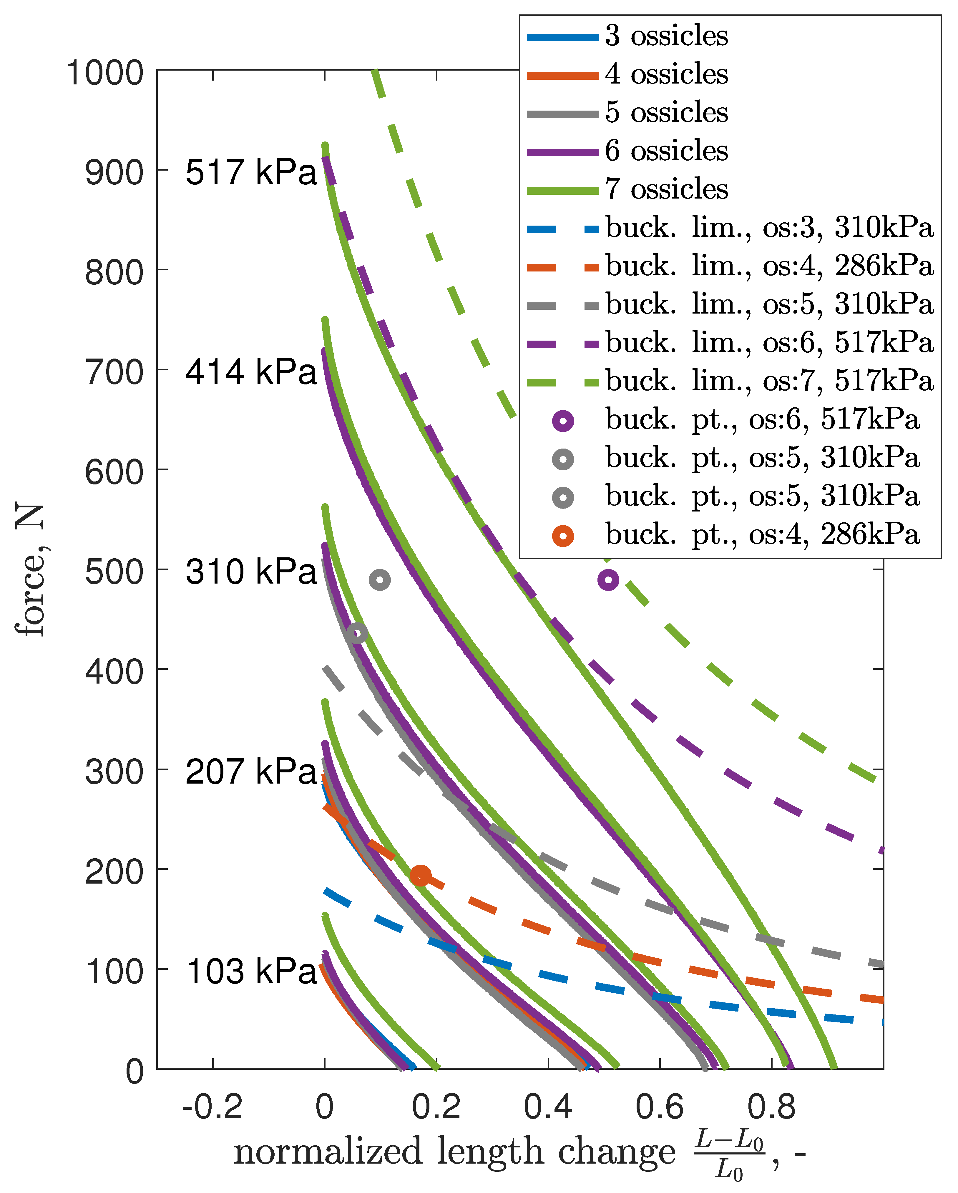
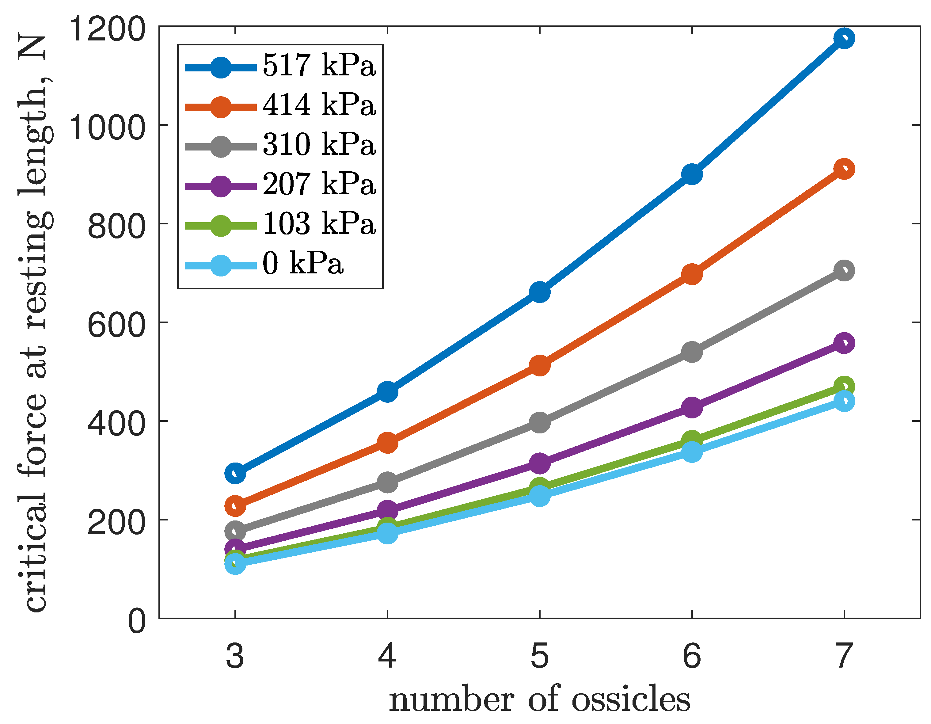
4. Buckling Analysis
Euler Column Model
5. Discussion
6. Conclusions
7. Future Work
Author Contributions
Funding
Data Availability Statement
Acknowledgments
Conflicts of Interest
Abbreviations
| EFAM | Extensile Fluidic Artificial Muscles |
| FAM | Fluidic Artificial Muscles |
| PAM | Pneumatic Artificial Muscle |
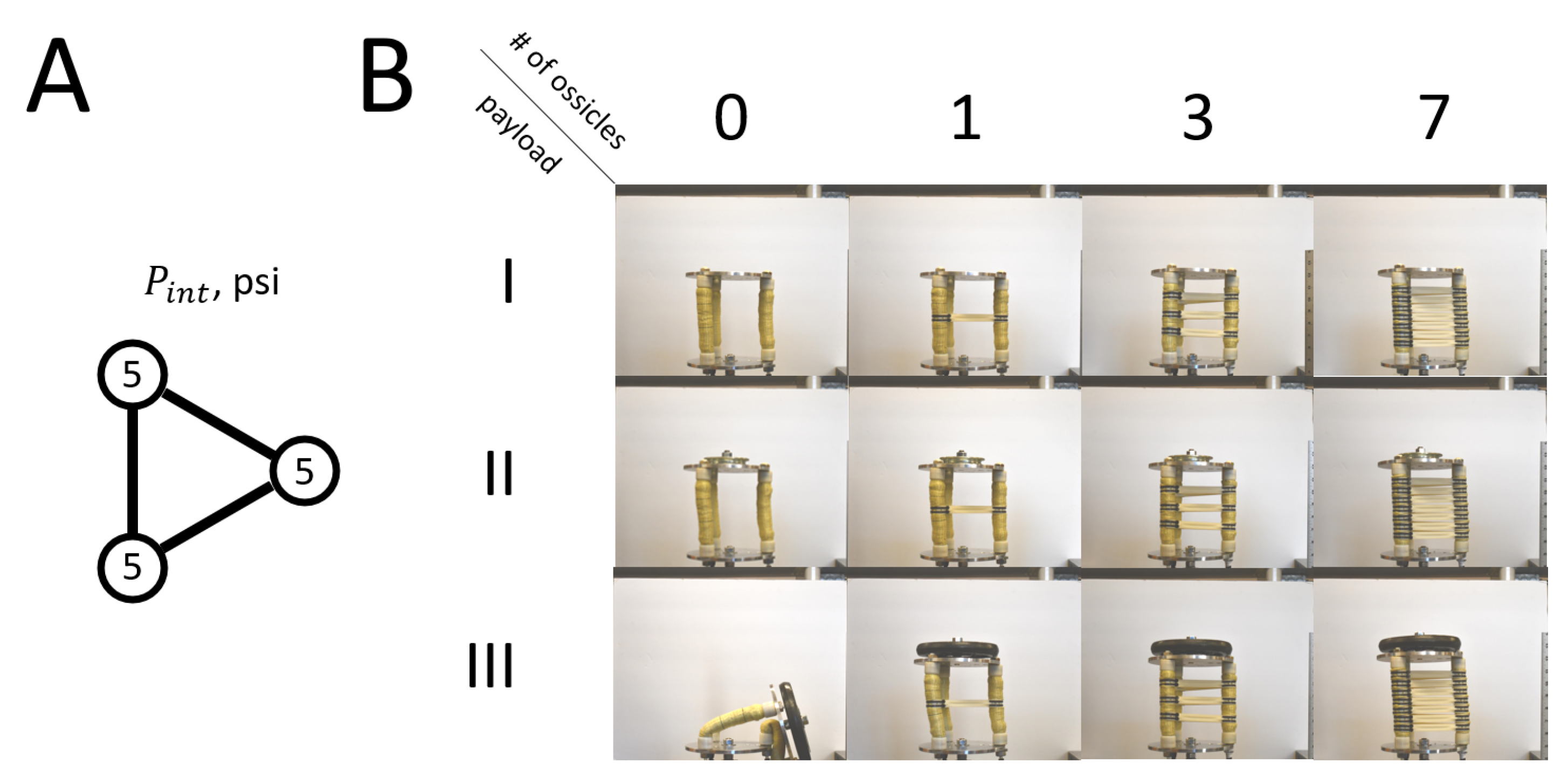
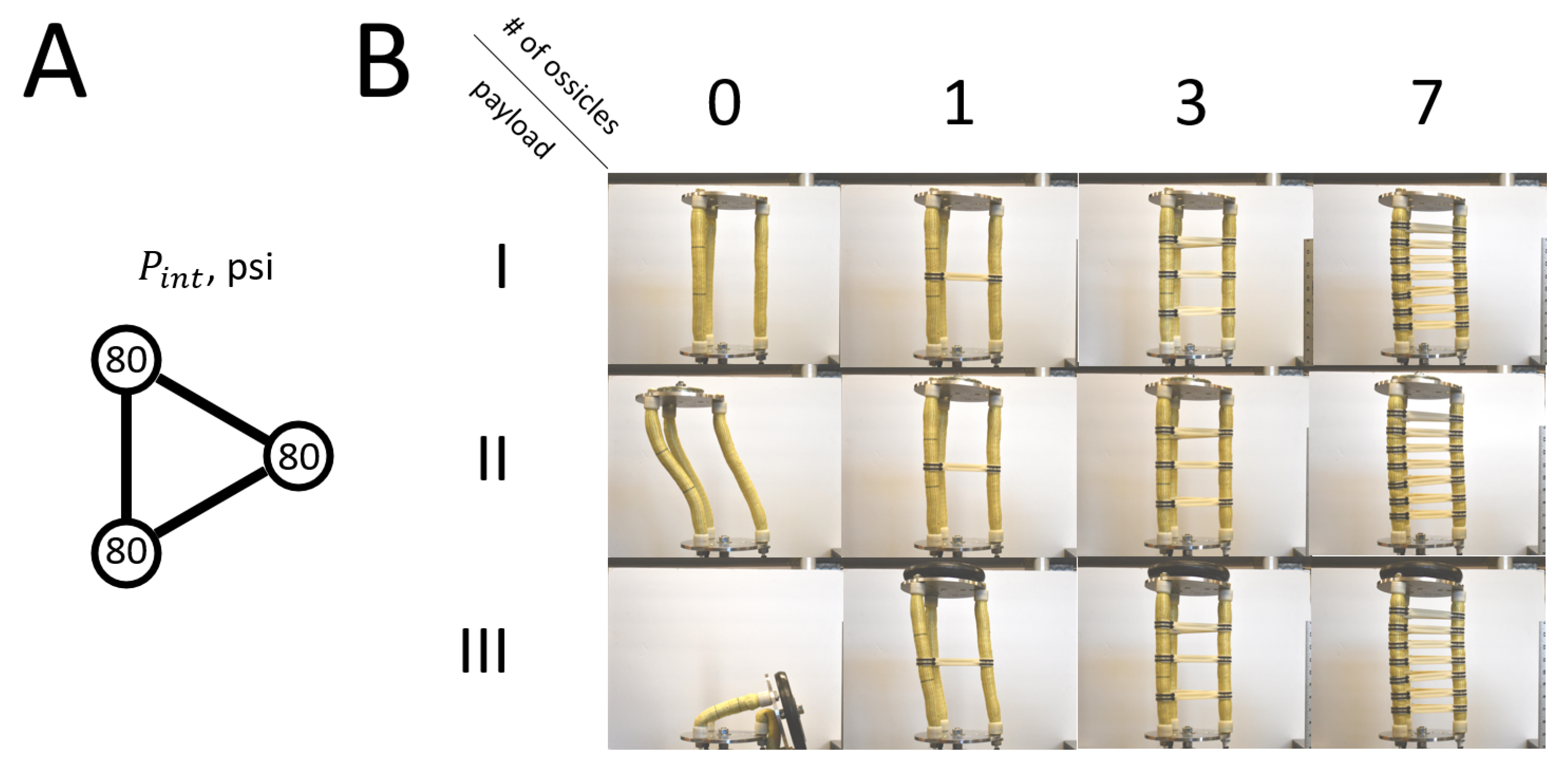
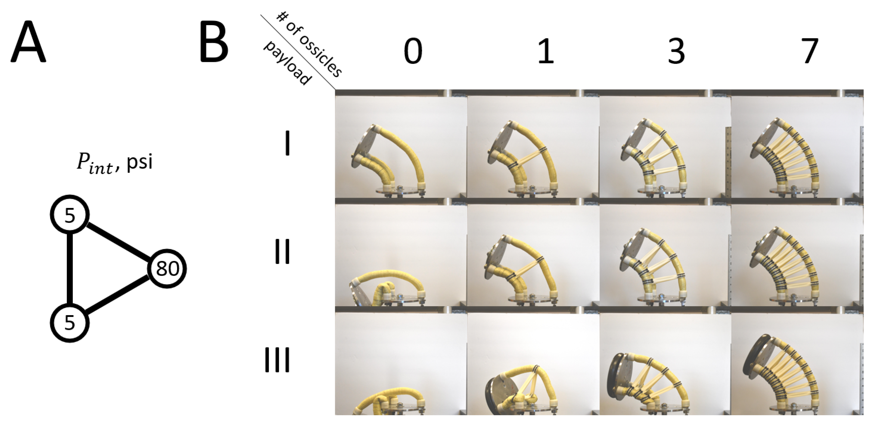
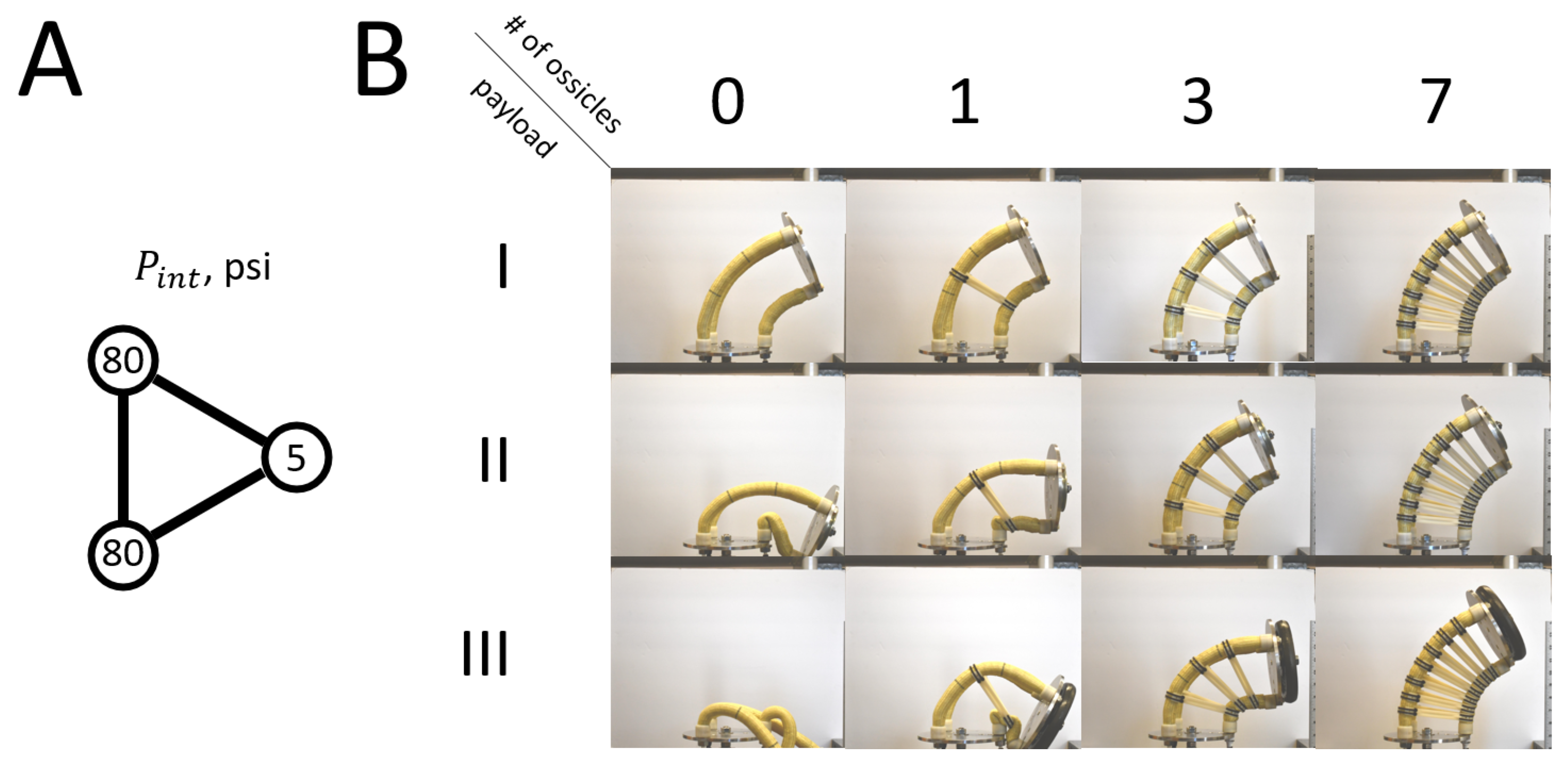
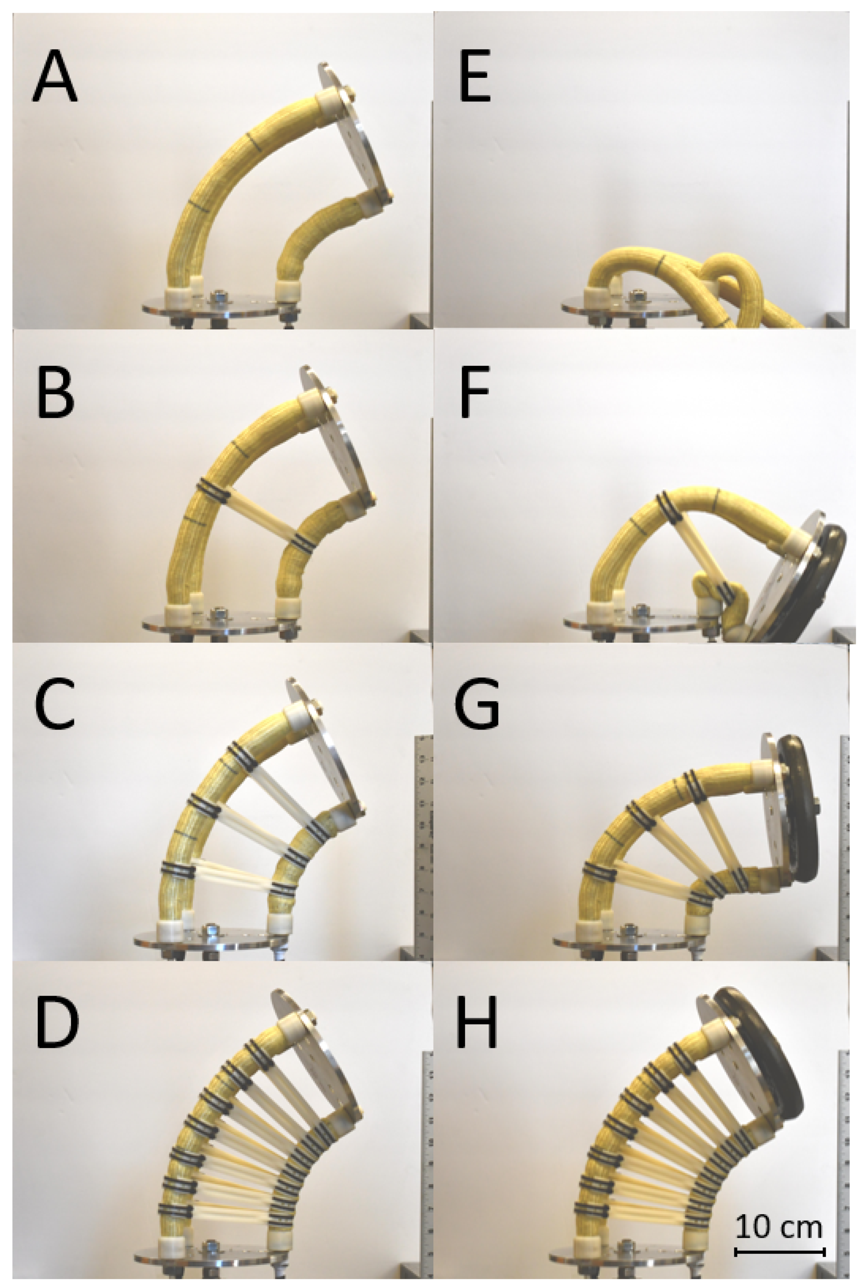
Appendix A. Pictographic Data—Spatial Behavior
References
- Davis, S. Pneumatic Actuators. Actuators 2018, 7, 62. [Google Scholar] [CrossRef]
- Majidi, C. Soft Robotics: A Perspective—Current Trends and Prospects for the Future. Soft Robot. 2013, 1, 5–11. [Google Scholar] [CrossRef]
- Trivedi, D.; Rahn, C.D.; Kier, W.M.; Walker, I.D. Soft Robotics: Biological Inspiration, State of the Art, and Future Research. Appl. Bionics Biomech. 2008, 5, 1176–2322. [Google Scholar] [CrossRef]
- Jones, B.A.; Walker, I.D. Practical kinematics for real-time implementation of continuum robots. IEEE Trans. Robot. 2006, 22, 1087–1099. [Google Scholar] [CrossRef]
- Neppalli, S.; Jones, B.; McMahan, W.; Chitrakaran, V.; Walker, I.; Pritts, M.; Csencsits, M.; Rahn, C.; Grissom, M. Octarm—A soft robotic manipulator. In Proceedings of the IEEE/RSJ International Conference on Intelligent Robots and Systems, San Diego, CA, USA, 29 October–2 November 2007; p. 2569. [Google Scholar]
- Webster, R.J., III; Jones, B.A. Design and kinematic modeling of constant curvature continuum robots: A review. Int. J. Robot. Res. 2010, 29, 1661–1683. [Google Scholar] [CrossRef]
- Walker, I.D. Continuous backbone “continuum” robot manipulators. ISRN Robot. 2013, 2013, 1–19. [Google Scholar] [CrossRef]
- Pritts, M.B.; Rahn, C.D. Design of an artificial muscle continuum robot. In Proceedings of the IEEE International Conference on Robotics and Automation, New Orleans, LA, USA, 26 April–1 May 2004; Volume 5, pp. 4742–4746. [Google Scholar]
- McMahan, W.; Chitrakaran, V.; Csencsits, M.; Dawson, D.; Walker, I.D.; Jones, B.A.; Pritts, M.; Dienno, D.; Grissom, M.; Rahn, C.D. Field trials and testing of the OctArm continuum manipulator. In Proceedings of the 2006 IEEE International Conference on Robotics and Automation—ICRA 2006, Orlando, FL, USA, 15–19 May 2006; pp. 2336–2341. [Google Scholar]
- Trivedi, D.; Lotfi, A.; Rahn, C.D. Geometrically Exact Models for Soft Robotic Manipulators. Trans. Rob. 2008, 24, 773–780. [Google Scholar] [CrossRef]
- Chawla, A.; Frazelle, C.; Walker, I. A Comparison of Constant Curvature Forward Kinematics for Multisection Continuum Manipulators. In Proceedings of the 2018 Second IEEE International Conference on Robotic Computing (IRC), Laguna Hills, CA, USA, 31 January–2 February 2018; pp. 217–223. [Google Scholar]
- Giannaccini, M.E.; Xiang, C.; Atyabi, A.; Theodoridis, T.; Nefti-Meziani, S.; Davis, S. Novel Design of a Soft Lightweight Pneumatic Continuum Robot Arm with Decoupled Variable Stiffness and Positioning. Soft Robot. 2018, 5, 54–70. [Google Scholar] [CrossRef]
- Guan, Q.; Sun, J.; Liu, Y.; Wereley, N.M.; Leng, J. Novel Bending and Helical Extensile/Contractile Pneumatic Artificial Muscles Inspired by Elephant Trunk. Soft Robot. 2020, 7, 597–614. [Google Scholar] [CrossRef] [PubMed]
- Tomholt, L.; Friesen, L.J.; Berdichevsky, D.; Fernandes, M.C.; Pierre, C.; Wood, R.J.; Weaver, J.C. The structural origins of brittle star arm kinematics: An integrated tomographic, additive manufacturing, and parametric modeling-based approach. J. Struct. Biol. 2020, 11, 107481. [Google Scholar] [CrossRef] [PubMed]
- Pillsbury, T. Soft Robotic Appendages Using Pneumatic Artificial Muscles. Ph.D. Thesis, University of Maryland, College Park, MD, USA, 2018. [Google Scholar]
- Olson, G.; Woronowicz, B.; Mengüç, Y. Characterization of a Class of Soft Bending Arms. In Proceedings of the 2019 2nd IEEE International Conference on Soft Robotics (RoboSoft), Seoul, Republic of Korea, 14–18 April 2019; pp. 462–469. [Google Scholar] [CrossRef]
- Olson, G.; Hatton, R.L.; Adams, J.A.; Mengüç, Y. An Euler–Bernoulli beam model for soft robot arms bent through self-stress and external loads. Int. J. Solids Struct. 2020, 207, 113–131. [Google Scholar] [CrossRef]
- Godage, I.S.; Medrano-Cerda, G.A.; Branson, D.T.; Guglielmino, E.; Caldwell, D.G. Dynamics for variable length multisection continuum arms. Int. J. Robot. Res. 2016, 35, 695–722. [Google Scholar] [CrossRef]
- Ansari, Y.; Manti, M.; Falotico, E.; Cianchetti, M.; Laschi, C. Multiobjective Optimization for Stiffness and Position Control in a Soft Robot Arm Module. IEEE Robot. Autom. Lett. 2018, 3, 108–115. [Google Scholar] [CrossRef]
- Sridar, S.; Majeika, C.J.; Schaffer, P.; Bowers, M.; Ueda, S.; Barth, A.J.; Sorrells, J.L.; Wu, J.T.; Hunt, T.R.; Popovic, M. Hydro Muscle—A novel soft fluidic actuator. In Proceedings of the 2016 IEEE International Conference on Robotics and Automation (ICRA), Stockholm, Sweden, 16–21 May 2016; pp. 4014–4021. [Google Scholar] [CrossRef]
- Skorina, E.H.; Onal, C.D. Soft Pneumatic Actuators: Modeling, Control, and Application. In Smart Materials: Considerations on Earth and in Space; Rasmussen, L., Ed.; Springer International Publishing: Cham, Switzerland, 2022; pp. 129–219. [Google Scholar] [CrossRef]
- Kim, J.Y.; Mazzoleni, N.; Bryant, M. Modeling of Resistive Forces and Buckling Behavior in Variable Recruitment Fluidic Artificial Muscle Bundles. Actuators 2021, 10, 42. [Google Scholar] [CrossRef]
- Mazzoleni, N.; Kim, J.Y.; Bryant, M. Motor unit buckling in variable recruitment fluidic artificial muscle bundles: Implications and mitigations. Smart Mater. Struct. 2022, 31, 035004. [Google Scholar] [CrossRef]
- Hocking, E.G.; Wereley, N.M. Analysis of nonlinear elastic behavior in miniature pneumatic artificial muscles. Smart Mater. Struct. 2012, 22, 014016. [Google Scholar] [CrossRef]
- Woods, B.K.S.; Gentry, M.F.; Kothera, C.S.; Wereley, N.M. Fatigue life testing of swaged pneumatic artificial muscles as actuators for aerospace applications. J. Intell. Mater. Syst. Struct. 2012, 23, 327–343. [Google Scholar] [CrossRef]
- Garbulinski, J.; Balasankula, S.C.; Wereley, N.M. Characterization and Analysis of Extensile Fluidic Artificial Muscles. Actuators 2021, 10, 26. [Google Scholar] [CrossRef]
- Kothera, C.; Jangid, M.; Sirohi, J.; Wereley, N. Experimental characterization and static modeling of McKibben actuators. J. Mech. Des. Trans. ASME 2009, 131, 091010. [Google Scholar] [CrossRef]
- Pillsbury, T.E.; Wereley, N.M.; Guan, Q. Comparison of contractile and extensile pneumatic artificial muscles. Smart Mater. Struct. 2017, 26, 095034. [Google Scholar] [CrossRef]
- Chou, C.P.; Hannaford, B. Measurement and modeling of McKibben pneumatic artificial muscles. IEEE Trans. Robot. Autom. 1996, 12, 90–102. [Google Scholar] [CrossRef]
- Raj, P.P.; Ramasamy, V. Strength of Materials, 1st ed.; Dorling Kindersley: New Delhi, India, 2012. [Google Scholar]
- Popov, E.P. Mechanics of Materials, 2nd ed.; Civil Engineering and Engineering Mechanics Series; Prentice-Hall, Inc.: Englewood Cliffs, NJ, USA, 1976. [Google Scholar]
- Garbulinski, J. Extensile Fluidic Artificial Muscles in Payload-Carrying Continuum Soft Robots. Ph.D. Thesis, University of Maryland, College Park, MD, USA, 2023. [Google Scholar]

| Part Name | Quantity | Material | Length cm (in) | Diameter cm (in) |
|---|---|---|---|---|
| End fitting | 2 | Aluminium | 2.54 (1) | 2.133 (0.84) |
| Swage tube | 2 | Aluminium | 2.54 (1) | inner: 2.25 (0.884) outer: 2.54 (1) |
| Elastomeric tube | 1 | Soft latex rubber | 17.78 (7) | inner: 1.9 (3/4) outer: 2.22 (7/8) |
| Braided sleeve | 1 | Biaxial Kevlar | 50.8 (20) at | 1.905 (3/4) at |
| Ossicles | P [kPa] | L [cm] | F [N] | K | |
|---|---|---|---|---|---|
| 4 | 286.1 | 19.94 | 440.8 | 19.24 | 4.82 |
| 5 | 310.3 | 18.7 | 489.3 | 17.45 | 3.18 |
| 5 | 310.3 | 18.01 | 435.9 | 15.89 | 3.5 |
| 6 | 517.1 | 25.66 | 489.3 | 17.13 | 2.86 |
Disclaimer/Publisher’s Note: The statements, opinions and data contained in all publications are solely those of the individual author(s) and contributor(s) and not of MDPI and/or the editor(s). MDPI and/or the editor(s) disclaim responsibility for any injury to people or property resulting from any ideas, methods, instructions or products referred to in the content. |
© 2024 by the authors. Licensee MDPI, Basel, Switzerland. This article is an open access article distributed under the terms and conditions of the Creative Commons Attribution (CC BY) license (https://creativecommons.org/licenses/by/4.0/).
Share and Cite
Garbulinski, J.; Balasankula, S.C.; Wereley, N.M. Increasing Payload Capacity of a Continuum Soft Robot Using Bio-Inspired Ossicle Reinforcement. Actuators 2024, 13, 265. https://doi.org/10.3390/act13070265
Garbulinski J, Balasankula SC, Wereley NM. Increasing Payload Capacity of a Continuum Soft Robot Using Bio-Inspired Ossicle Reinforcement. Actuators. 2024; 13(7):265. https://doi.org/10.3390/act13070265
Chicago/Turabian StyleGarbulinski, Jacek, Sai C. Balasankula, and Norman M. Wereley. 2024. "Increasing Payload Capacity of a Continuum Soft Robot Using Bio-Inspired Ossicle Reinforcement" Actuators 13, no. 7: 265. https://doi.org/10.3390/act13070265