Abstract
Morphing airplane technology is currently a focal point of research. For morphing airplanes, besides effective morphing strategies and control schemes, the hinge moment at the root of the vertical tail during morphing is a critical factor influencing flight safety. To prevent failure in tail morphing due to excessive hinge moments, this paper analyzes the hinge moment characteristics of the variable vertical tail structure in high-speed flight, based on a flying wing model from the China Aerodynamics Research and Development Center. The proposed adaptive morphing tail hinge moment reduction (AMTHR) method is model-free, utilizing real-time data to dynamically adjust the rudder and reduce hinge moments without requiring prior knowledge of system dynamics. This method utilizes the concept of extremum-seeking control by introducing periodic perturbations to the system and adjusting the control input based on their impact on the output. This approach drives the output toward an extremum point, enabling real-time reduction of the vertical tail hinge moment. Finally, the simulation analysis is carried out under the conditions of no wind and gust disturbance, and the effect of this method on the load reduction of the tail hinge moment is verified.
1. Introduction
Tail-less–fuselage blended aircraft exhibit high aerodynamic lift efficiency and excellent stealth capabilities. Moreover, the omnidirectional low radar reflection area and penetrating counter-air capability of high-speed tail-less aircraft will further enhance combat effectiveness, playing a crucial role in anti-access/area denial environments [1], thus potentially revolutionizing the future of air combat operations. Therefore, in the development of future advanced fighters, countries worldwide are converging towards high-speed tail-less configurations with a small aspect ratio. Examples include the U.S. B-2 stealth bomber [2], Boeing’s X-45 series UAV [3], the ‘Thunder’ UAV [4], and the Next-Generation Air Dominance (NGAD) fighter [5]. The concept designs of these next-generation combat aircraft clearly emphasize stealth and high-speed flight capabilities. Consequently, they generally adopt low-aspect-ratio tail-less or ‘V’-tail wing–body fusion layouts. To meet the demands for stealth and maneuverability, under different mission scenarios, morphing technology can be applied to tail-less wing–body fusion aircraft [6,7,8]. The morphing tail blended-wing–body aircraft switches between the tail and tail-less layout by altering the tail deflection angle, enabling combat maneuvers in a tailed configuration and cruising or penetrating in a tail-less stealth configuration [9]. An example is the low-aspect-ratio flying wing model from the China Aerodynamics Research and Development Center [10]. This design features a morphing tail located at the rear. During stealth cruising, the wings and tail retract, forming a typical flying wing configuration, providing a high lift-to-drag ratio and improved stealth capability. When high maneuverability is required, the morphing tail deploys, also meeting the yaw control needs for crosswinds, takeoff, and landing. This paper uses the flying wing model proposed in [10] to study the morphing tail configuration.
However, a series of morphing flight problems caused by the introduction of variable tails need to be solved by designing active control to ensure smooth flight during the entire morphing process. First, before the variable tail operation, the aircraft is in a tail-less body fusion layout. At this stage, challenges such as lateral instability, weak yaw control efficiency, and significant lateral control coupling exist. Secondly, in the process of high-speed variable tail operation, the aircraft converts from a tail-less to a tailed layout, leading to a change in the aircraft motion mode [11]. Consequently, the control system at this phase must adapt to the drastic changes in the aircraft’s stability. Additionally, the coupling effects resulting from tail morphing introduce a range of issues such as the change in control effectiveness and rudder allocation. Furthermore, a unique challenge for this phase is the reduction of aerodynamic loads added to the hinge moment at the root of the vertical tail [12,13]. As the hinge moment at the root of the tail increases with flight speed, how to meet the hinge moment demand within the limited capacity of the morphing tail drive motor is crucial for achieving variable tail flight and ensuring flight safety. This aspect constitutes a prerequisite factor and a focal point of this study.
At present, there are numerous studies on morphing aircraft, but most of them focus on design [14,15], modeling [16], aerodynamic analysis [17], morphing strategy [18,19], morphing flight control [20,21,22], and so on. The nonlinear dynamic modeling of morphing aircraft serves as the foundation for analyzing aircraft characteristics and studying integrated morphing and flight control. However, in high-speed flight, particular attention is required for the hinge moment characteristics of variable tail structures under high dynamic pressure conditions, which is the decisive factor for the realization of the variable tail. There is not much research in this area. This paper designs a morphing aircraft based on the basic aircraft configuration in Ref. [10], focusing on investigating hinge moment reduction schemes for the morphing tail.
The remaining contents of this paper are organized as follows. Section 2 introduces the morphing aircraft model and the tail morphing configuration, and provides the initial numerical investigation. In Section 3, the adaptive morphing tail hinge moment reduction (AMTHR) method is proposed. Section 4 conducts numerical simulations to validate the effectiveness of the proposed approach. The last section summarizes the whole work.
2. Flight Mechanics Model Formulation
2.1. Aircraft Model
The prototype of the morphing airplane studied in this paper is shown in Figure 1a [10]. This aircraft features a large sweep-angle diamond wing, which is advantageous for reducing shock wave drag and enhancing supersonic performance. In this paper, its configuration is further refined and updated to Figure 1b. When the tail is fully retracted, the aircraft is a tail-less stealth configuration; when the tail is fully deployed, it is a tailed maneuvering configuration. The vertical tail deformation diagram is shown in Figure 1c. The basic parameters of the morphing tail aircraft are shown in Table 1.
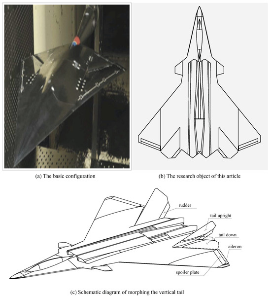
Figure 1.
Scheme of a morphing tail aircraft.

Table 1.
The basic parameters of the morphing tail aircraft.
2.2. Tail Deformation Setting
As shown in Figure 1c, the vertical tail is symmetrically deformed, with the rudder hinged on the vertical tail, moving in conjunction with it. This vertical tail structure can be simplified into a combination of a linkage and hinge, possessing two rotational degrees of freedom, as depicted in Figure 2.
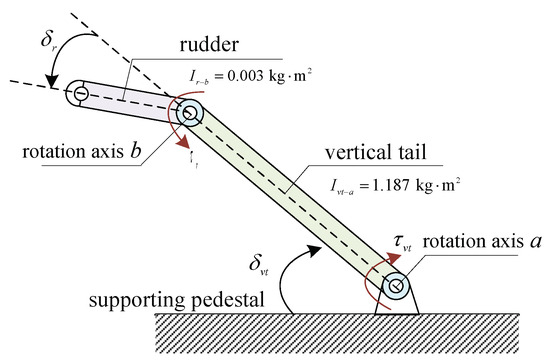
Figure 2.
Diagram of simplified deformation of vertical tail structure.
In the diagram, the inertia moments of the vertical tail and the rudder around rotation axes a and b are and , respectively. The rudder’s moment of inertia is smaller than that of the vertical tail. The deflection angle of the rudder is . The values provided by rotation axes a and b to overcome the aerodynamic hinge moments are and , respectively. The deformation coefficient of the tail is , defined as follows:
where the vertical tail deflection range of is –, and the deformation coefficient is determined in Equation (1). Subsequently, the impact of the deformation coefficient on the aerodynamic characteristics of the morphing tail aircraft will be established.
Table 2 presents the changes in the moment of inertia characteristics under a different mass and deformation coefficient . It can be observed from the table that as the vertical tail is lowered, the body gradually transitions from a tailed to a tail-less configuration. During this transition, the and show an increasing trend, whereas the changes little, and the changes most drastically, reaching 40%. Therefore, it is crucial to consider the potential impact of the transformation process on inertial coupling.
Table 2.
The moment of inertia characteristics with and mass.
2.3. Analysis of Tail Hinge Moment Characteristics
Since the vertical tail deformation process studied is continuous and slow, the effect of the deformation rate on aerodynamics is not considered. Aerodynamic forces and moment coefficients under various conditions are calculated based on CFD, yielding quasi-steady-state aerodynamic coefficients. The changes in the aerodynamic characteristics during the vertical tail deformation process can then be obtained by interpolating or fitting these aerodynamic coefficients. The process of obtaining the aerodynamic model for the entire aircraft during the continuous transition of the vertical tail is as follows: the vertical tail angle varies from to . We take the configuration where the vertical tail is fully lowered (at ) and forms a continuous surface with the main wing as the baseline configuration. By calculating the aerodynamic data for the aircraft at different vertical tail angles and comparing them with the baseline configuration, we obtain the aerodynamic increment data caused by changes in the vertical tail angle. These increment data are interpolated according to the variation in the vertical tail angle to derive the aerodynamic model for the entire transition process of the vertical tail, which serves as the basis for our analysis and simulation.
Therefore, all force and moment coefficients can be expressed as the sum of a baseline value and an incremental value. The aerodynamic and moment coefficients for the tail-off configuration () are taken as the baseline, with the incremental aerodynamic coefficients resulting from the vertical tail variation and control surface deflection. Taking the lift coefficient as an example, it can be represented as follows:
where is the baseline value related to the angle of attack and Mach number, represents the lift coefficient increment due to the vertical tail variation, and represents the lift coefficient increment from the coupling of control surface deflection and vertical tail variation. Both the baseline value and increments can be described using interpolation tables or fitted functions.
Figure 3 shows the baseline aerodynamic characteristics of the longitudinal and lateral–directional axes for the variable vertical tail aircraft. Figure 4 presents the variation curves of the aerodynamic derivative increments caused by the deformation, relative to the baseline values of the tail-off configuration, for both longitudinal and lateral–directional axes. To minimize the coupling effects caused by changes in the angle of attack, only the aerodynamic derivative variations at small angles of attack () are considered.
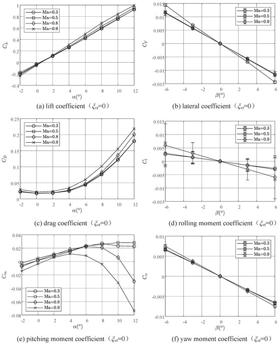
Figure 3.
The baseline aerodynamic characteristics.
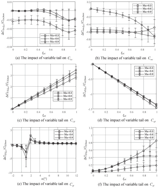
Figure 4.
The impact of the variable vertical tail process on aerodynamic derivatives.
Figure 3 and Figure 4 show that as increases from 0 to 1, the lift curve slope of the main body decreases by 1% to 3%, with the reduction positively correlated with the Mach number. Additionally, the variable vertical tail significantly affects the longitudinal projection area of the vertical tail. The derivative of the side force coefficient with respect to the sideslip angle increases several times with the variable coefficient, approximately threefold at . Consequently, the aircraft’s lateral overload effectively reflects changes in the sideslip angle, allowing for the reduction of the sideslip angle through control methods that suppress lateral overload.
The hinge moment is generated by the connection axis between the vertical tail and the fuselage to overcome aerodynamic loads. In the process of varying the vertical tail, the hinge moment directly influences the success of the operation. Therefore, it is necessary to analyze the hinge moment at the rotation axis for the vertical tail. The calculation formula of the hinge moment on a single side of the tail is as follows:
where and are the reference area and length of the tail, respectively. denotes the hinge moment coefficient, which is influenced by a combination of the angle of attack , the rudder angle , and the deformation coefficient .
The rudder angle for balancing the hinge moment is calculated at different angles of attack and deformation coefficients; the trim surface obtained is shown in Figure 5a. By projecting this surface onto a plane with as the horizontal axis and as the vertical axis, the numerical relationship between the rudder trim angle with and can be obtained (Figure 5b). Figure 5b shows that the increase in the or leads to an increase in the rudder trim angle. In the entire process, the maximum rudder trim angle reaches , which is approximately 33% of the maximum rudder angle (). This result shows that within the allowable range, the rudder can be used in conjunction with the variable tail to counteract the hinge moment, thereby reducing the demand for the variable vertical tail drive motor.
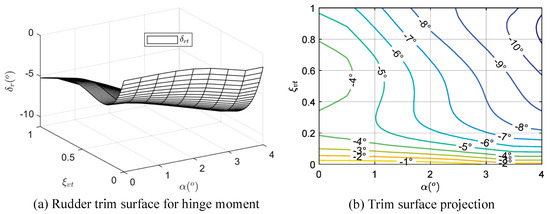
Figure 5.
The rudder trim characteristics for hinge moment.
3. Adaptive Morphing Tail Hinge Moment Reduction
This section presents an adaptive morphing tail hinge moment reduction method, which aims to operate without relying on the model and computes the required actuator commands in real time to achieve a “floating” effect of the tail in the variation process. To achieve this, the section first analyzes vertical tail hinge moment alleviation, then designs the unloading method based on the extremum-seeking control concept, and finally provides the final design scheme.
3.1. Analysis of Tail Hinge Moment Reduction
The analysis in Section 2.3 indicates that by synchronizing the rudder with the tail deformation, it is possible to offset the hinge moment at the tail root. Figure 6 shows the calculated hinge moment at the root of the tail during the continuous deformation process at 0.8 Ma and 10,000 m. This figure shows that when the rudder is not deflected, the hinge moment increases with the deformation coefficient , exhibiting an approximate quadratic function between and . When , the hinge moment reaches its maximum, at 269 Nm; when , the hinge moment is the minimum, with a value of 17 Nm. If the rudder is deflected according to the trim relation obtained in Section 2.3, the hinge moment curve represented by the dashed line in Figure 6 can be obtained. In the entire deformation process, the rudder’s maximum deflection is , which is 1/3 of the maximum rudder, bringing the close to zero.
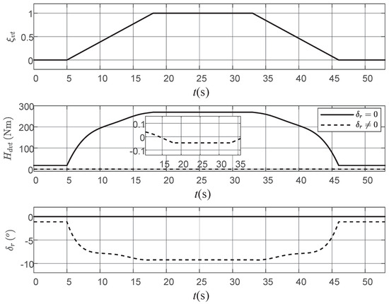
Figure 6.
Hinge moment during the tail transformation.
Based on the analysis and simulation results, it can be concluded that the rudder follow-up deflection can effectively reduce the hinge moment during the variable tail. However, there is a problem of uncertainty through the interpolation of the rudder with the deformation coefficient and angle of attack. First, the hinge moment calculation model (interpolation model) is constrained by computational accuracy and the complexity of flight conditions, making it unable to always reflect the true moment characteristics. This limitation makes it difficult to create a model that covers all maneuvering requirements. Second, there are environmental uncertainties during the variable tail flight, such as gusts and turbulence. In these cases, compensating rudder deflections based on the prior hinge moment result might lead to opposite outcomes, switching from reducing to increasing the hinge moment.
Therefore, to reduce the hinge moment at the tail root and achieve a “floating” effect of the tail in the variation process, ultimately realizing adaptive tail transformation, a control strategy is needed that does not rely on models while meeting the real-time computational requirement.
3.2. AMTHR Based on ESC
Extreme-seeking control (ESC) [23] is a model-independent, data-driven type of control method [24] that guarantees convergence under certain conditions [25]. ESC adjusts the control input by introducing a periodic perturbation to the system and analyzing the effect on the system output, thereby steering the output towards an extremum. As shown in Figure 7, a periodic sinusoidal signal is injected into the input u of the physical system, and the cost function J is calculated based on the output y from the system sensors. By estimating the gradient of the cost function J, the optimal estimate of the control input, , is obtained.
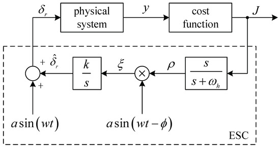
Figure 7.
Diagram of the ESC method.
The advantage and principle of ESC lie in its ability to adjust control inputs for minimal target values via online gradient optimization, without the need for knowledge about the complex nonlinear relationship between inputs and outputs [26]. This method is widely applied in the field of photovoltaic power generation [27,28], where it controls the orientation of solar panels to maximize energy output. Additionally, successful applications of ESC include controlling the maximum braking force during anti-lock braking in automobiles [29], minimizing energy consumption during formation flying [30], and maximizing flight duration in turbulent conditions [31]. These applications all involve clear control objectives that require maintaining near the optimal level.
Inspired by the ECS concept, this study addresses the issue of hinge moment unloading during the adaptive variable tail flying process. The control input, represented by the rudder deflection angle , aims to maintain the hinge moment at the root of the vertical tail, keeping the minimum within the range of deformation coefficient . The design process of the extreme value function of the hinge moment based on ESC is given below. According to Figure 7, the rudder with sinusoidal perturbation can be expressed as follows:
From Figure 8, it can be observed that under the sinusoidal input (4), the cost function J formed by the output y (hinge moment ) also exhibits a sinusoidal trend around its mean value. By applying a high-pass filter to remove the low-frequency component of signal J, which represents the mean value of the cost function, an oscillatory signal is obtained, as shown in Equation (5):
where represents the filtering frequency of the high-pass filter; its selection depends on the input sinusoidal perturbation frequency w. The signal is multiplied by the input signal after phase shifting, which denotes , resulting in the demodulated signal :
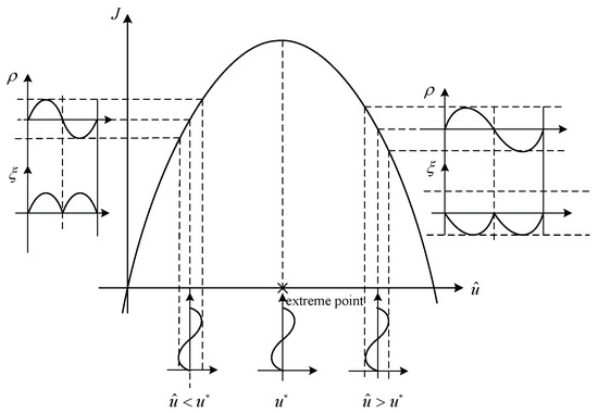
Figure 8.
Principle diagram of extreme value optimization.
As shown in Figure 8, when is to the left of the optimal value (where corresponds to the maximum), the computed value of is always positive. Conversely, when is to the right of , is negative. Therefore, by integrating , an estimate of the optimal value can be obtained:
where k is the integral gain, which represents the learning rate. A larger value of k indicates a more pronounced impact of the variation in on the gradient of J.
An analysis of Equation (7) shows that when the gradient of J is relatively large, the system state under control input will converge more rapidly towards the extremum. Assuming the physical system has a unit constant of 1, and the objective function J is a simple function of , J can be expressed as
The first-order Taylor series expansion of Equation (8) at is obtained:
Combined with Equation (9), the approximate calculation result of signal is
Combining Equation (6) and Equation (10), the mean value of in one period is calculated as
It can be seen from Equation (11) that is proportional to the derivative of the objective function J with respect to .
3.3. AMTHR Scheme
In practical flight operations, cannot be directly measured. Therefore, approximations such as the current or voltage of the tail motor can be used to reflect the magnitude of the hinge moment. Thus, the ESC problem concerning is transformed into an optimization problem regarding the current or voltage. For ease of simulation and analysis, this study evaluates the effectiveness of ECS in active aerodynamic unloading and adaptive variable tail applications based on its control effect on the hinge moment at the vertical tail. The conclusion can be extrapolated to the control of the current or voltage in actual flight scenarios.
Constructing the cost function for AMTHR is as follows:
By finding the maximum value of the cost function (12), the rudder deflection corresponding to the minimum hinge moment of the variable tail can be obtained.
As shown in Figure 9, an adaptive variable tail simulation model is constructed, where and represent the transfer functions of the vertical tail and rudder actuator, respectively. The calculation steps of the AMTHR method can be divided into the following steps:
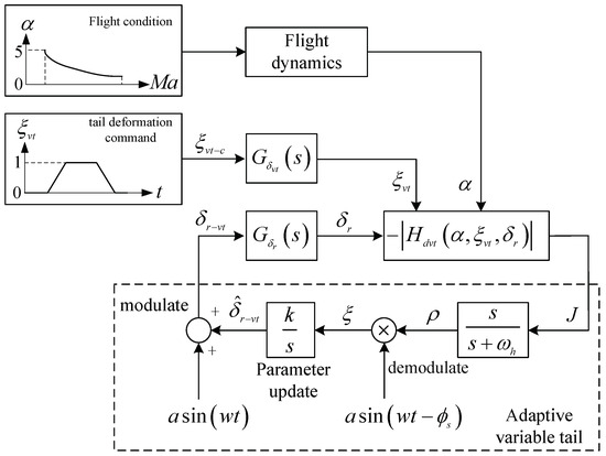
Figure 9.
Scheme diagram of AMTHR.
- (1)
- A sinusoidal perturbation with amplitude a and frequency w is injected into the control input signal to modulate ;
- (2)
- A high-pass filter with a cutoff frequency of is utilized to compute the gradient of the cost function J, and then it is multiplied by the signal after phase shifting for demodulation;
- (3)
- The demodulated signal is integrated and multiplied by the learning rate k to obtain an estimated value of the optimal rudder angle after parameter update.
The parameter selection of AMTHR is presented in Table 3. A higher value of the learning rate k leads to faster convergence of AMTHR. However, the excessively large k may result in significant oscillations or even divergence in control [25]. The excitation frequency w and the high-pass filter cutoff frequency are selected based on the time scale [12]. From the perspective of time scale, the excitation frequency w should be chosen such that the time scale of excitation is slower than the variable tail frequency . Additionally, the value of should be less than w. Based on the above selection principle, the parameter selection inequality relationship is derived, and values are chosen according to 3–5 times of the time scale separation principle [32]. The selection of the excitation amplitude should exceed the rudder surface clearance and dead zone while also sufficiently stimulating the hinge moment of the vertical tail actuator. The phase shift angle , can be calculated by substituting into the rudder transfer function .
Table 3.
Parameters of AMTHR.
4. Numerical Simulation
In this section, we continue to use the flight conditions depicted in Figure 6 as the baseline, namely, 0.8 Mach and 10,000 m, to validate the effectiveness of the AMTHR method under no wind and gust wind conditions.
4.1. Load Reduction of Vertical Tail Hinge Moment
Firstly, the AMTHR method is applied under the same simulation conditions as Figure 6, and the simulation results are compared with those of Figure 6. Figure 10 presents the simulation results of the adaptive variable tail.
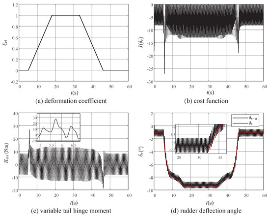
Figure 10.
Simulation results of adaptive variable tail process.
From Figure 10a,c, it can be observed that throughout the entire variable tail process, the hinge moment mostly ranges between −15 and 15 Nm. Compared to the simulation results without introducing rudder deflection in Figure 6, decreased by 95%. Observing Figure 10c, it is evident that when the deformation coefficient of the morphing tail airplane starts to change or reaches 0, exhibits a peak. However, this initial transient impact quickly converges within 1s, demonstrating the adaptive capability of the AMTHR method. Figure 10d compares the rudder interpolation result obtained via model trim relationships with the rudder command value output by AMTHR. It can be observed that the AMTHR method provides good estimation results for the optimal rudder deflection angle. The trend and value of and are nearly identical, reflecting the effectiveness of the AMTHR method. Additionally, exhibits low-frequency oscillations with an amplitude of approximately and a frequency of 1.6 Hz, primarily caused by the input excitation signal.
Although the frequency of this low-frequency oscillation is much lower than the control bandwidth of the rudder actuator, long-term rudder oscillation may lead to issues such as structural fatigue and reduced lifespan of the actuator. Therefore, the AMTHR method is only used during continuous dynamic variable sweep processes. When the morphing tail airplane in this study maintains a tail-less or tailed configuration for a long time, the tail is locked via the locking mechanism. This serves to prevent issues arising from continuous rudder excitation and to allocate more rudder control margin for yaw control.
4.2. Simulation under Gust Disturbance
Ref. [33] suggests that ECS exhibits potential robustness under random disturbances and speculates that ECS can effectively handle vertical gust effects. To verify the adaptability of AMTHR to vertical gusts, simulation experiments of this method under vertical gust conditions are conducted here.
In this section, we use a discrete gust model to validate the effectiveness of the proposed method. The reason for choosing this wind model is to assess the impact and effect of sudden gusts on the hinge moment, allowing us to examine the algorithm’s adaptability to wind disturbances in more severe conditions. In practice, discrete gusts are typically used to evaluate loads, while turbulence is used to assess the robustness of control systems. For the above reasons, we selected the discrete gust model to analyze the AMTHR algorithm. The vertical gust model is introduced into the adaptive vertical tail simulation. The vertical gust can be expressed as [34]
where denotes the integral of velocity with respect to time; is the length of the wind field; and expresses the gust amplitude. Following the conditions of moderate gust () at 10,000 m, and are chosen as 424 m and 4 m/s, respectively [34]. At 20 s, with a deformation coefficient , a gust in half-waveform is introduced. Figure 11 presents the simulation results for the entire process.
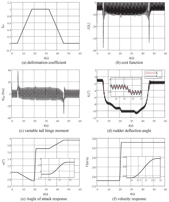
Figure 11.
Simulation results of adaptive variable tail process under gust.
From Figure 11e,f, it can be observed that the 4m/s gust results in an approximate increase in the angle of attack. To overcome the effects of gust disturbances, Figure 11d shows that under AMTHR control, the absolute value of the rudder command increases by and converges within 2 s. Furthermore, under gust disturbances, AMTHR achieves a good estimation of the optimal rudder value. As shown in Figure 11c, under gust disturbances, there are no significant fluctuations in hinge moment, and the steady-state response remains within the range of ±15 Nm.
To assess the characteristics of AMTHR under different gust intensities, as shown in Figure 12, 20 calculation points were selected based on a logarithmic distribution of different gust lengths and magnitudes. According to the flight quality standard 8785C [34], and considering a flight altitude of 10,000 m, the root mean square corresponds to mild (), moderate (), and severe () gusts. Combining this with Figure 12, the gust field lengths and amplitudes for different gust levels at discrete calculation points can be obtained. The gust field lengths and amplitudes are plugged into the gust model, and the simulation of the variable tail is conducted accordingly to obtain scattered results under different intensities and gust levels.
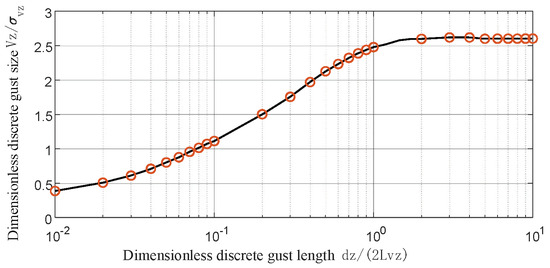
Figure 12.
Gust influence calculation point.
Referring to Figure 11a, gusts are introduced at t = 10 s to investigate the gust influence in the process of variable tail. The simulation time is 0–30 , covering both the continuous variable tail and stable tail flight phases. Figure 13 depicts the variations in the angle of attack and velocity induced by different gust levels. It can be observed that the angle of attack increment corresponding to severe gust is the largest, about , followed by moderate gust, about . The gust-induced angle of attack increment is smallest under mild gust, and is less than .
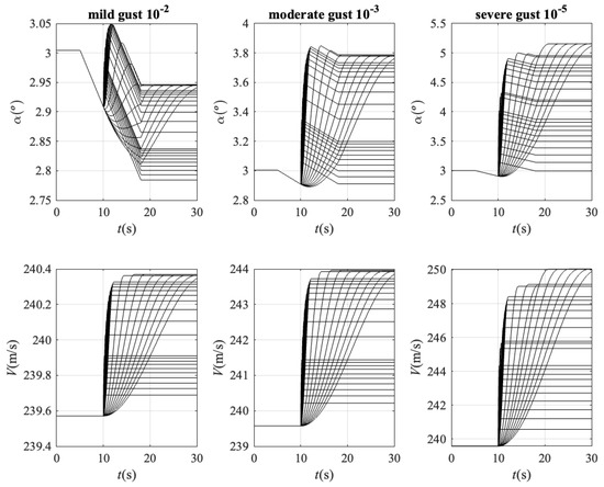
Figure 13.
Angle of attack and velocity dispersion under gust disturbance.
Figure 14 illustrates the simulation results of the AMTHR method under gusts of different scales and gust levels. The results indicate that regardless of mild, moderate, or severe gust, this method achieves the hinge moment load reduction at high-speed variable tail operations. As the gust level intensifies, the rudder deflection increases. In severe gusts, it even reaches 1/2 of the maximum deflection angle. Therefore, it is necessary to pay attention to the available yaw control margin in severe gusts, which underscores the importance of introducing locking mechanisms after completing the variable tail.
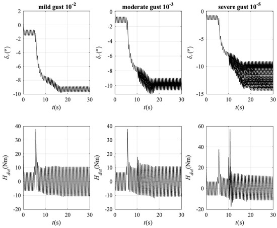
Figure 14.
Rudder and hinge moment dispersion under gust disturbance.
It is worth noting that even under the influence of gusts with severe gust probability, the maximum magnitude of the tail hinge moment under the AMTHR method is 60 Nm, which is only 20% of the case without active hinge moment unloading. Additionally, the steady-state value after gust disturbance convergence decreases to 5% of under the same condition in Figure 6. From both reliability and benefit perspectives, the AMTHR method demonstrates certain advantages.
5. Conclusions
In this paper, we address the specific issue of the morphing tail airplane, that is, the load reduction problem of the aerodynamic load on the hinge at the tail root. Based on the idea of ESC, an AMTHR scheme of hinge moment in the process of variable vertical tail is proposed to solve this problem. The AMTHR method introduces periodic perturbations to the system and adjusts the control input based on their impact on the output. This approach drives the output toward an extremum point, enabling real-time reduction of the vertical tail hinge moment. The numerical simulation results under no-wind conditions show that the AMTHR scheme can reduce the vertical tail hinge moment by 95%. Under various levels of turbulent gusts, this method achieves a hinge moment reduction of 83% or more during high-speed morphing. Therefore, the simulation results confirm the effectiveness of the proposed AMTHR scheme, demonstrating good adaptability and reliability even in gusty environments.
Author Contributions
Conceptualization, H.L. and R.C.; methodology, H.L. and R.C.; software, R.C.; validation, H.L. and R.C.; formal analysis, H.L. and R.C.; investigation, H.L. and R.C.; writing original draft preparation, R.C.; writing—review and editing, H.L. and R.C. All authors have read and agreed to the published version of the manuscript.
Funding
This research was funded by the Natural Science Foundation of Jiangsu Province of China
(No. BK20230560) and the National Natural Science Foundation of China (grant number No. 62303400,
92371116, 62373101, 62073075).
Institutional Review Board Statement
Not applicable.
Informed Consent Statement
Not applicable.
Data Availability Statement
Data are contained within the article.
Conflicts of Interest
Huitao Lyu was employed by the Shenyang Aircraft Design and Research Institute, Yangzhou Collaborative Innovation Research Institute Co., Ltd. The remaining authors declare that the research was conducted in the absence of any commercial or financial relationships that could be construed as a potential conflict of interest.
Abbreviations
The following abbreviations are used in this manuscript:
| AMTHR | adaptive morphing tail hinge moment reduction |
| NGAD | Next-Generation Air Dominance |
| ESC | Extreme-seeking control |
| Vertical tail angle | |
| Deformation coefficient | |
| Hinge moment of single tail | |
| Rudder angle | |
| Angle of attack | |
| Oscillation excitation signal | |
| J | Objective function of ESC |
References
- Bolander, C.R.; Kohler, A.J.; Hunsaker, D.F.; Myszka, D.; Joo, J. Development of smart structures for aircraft vibration and noise control. In Proceedings of the AIAA SCITECH 2023 Forum, National Harbor, ML, USA, 23–27 January 2023; pp. 1–6. [Google Scholar]
- Grellmann, H. B-2 aerodynamic design. In Proceedings of the Aerospace Engineering Conference and Show, Los Angeles, CA, USA, 3–15 February 1990; p. 1802. [Google Scholar]
- Brinker, J. Autonomous steering of the joint unmanned combat air system (J-UCAS) X-45A. In Proceedings of the AIAA 3rd “Unmanned Unlimited” Technical Conference, Chicago, IL, USA, 20–23 September 2004; p. 6575. [Google Scholar]
- Sepulveda, E.; Smith, H. Technology challenges of stealth unmanned combat aerial vehicles. Aeronaut. J. 2017, 121, 1261–1295. [Google Scholar] [CrossRef]
- Dean, S.E. USAF’s Next Generation Air Dominance Programme Status Report and Impact. Eur. Secur. Def. 2021, 10, 1–3. [Google Scholar]
- Wang, H.; Du, X.; Hu, Y. Investigation on the reduced-order model for the hydrofoil of the blended-wing-body underwater glider flow control with steady-stream suction and jets based on the POD method. Actuators 2024, 13, 194. [Google Scholar] [CrossRef]
- Zhang, B.; Li, Q.; Wang, T.; Wang, Z. Development of a bionic dolphin flexible tail experimental device driven by a steering gear. Actuators 2021, 10, 167. [Google Scholar] [CrossRef]
- Goetzendorf-Grabowski, T.; Kwiek, A. Study of the impact of aerodynamic model fidelity on the flight characteristics of unconventional aircraft. Appl. Sci. 2023, 13, 12522. [Google Scholar] [CrossRef]
- Ryseck, P.; Yeo, D.; Hrishikeshavan, V.; Chopra, I. Expanding the mission capabilities of a quadrotor biplane tail-sitter with morphing winglets. In Proceedings of the AIAA Scitech 2020 Forum, Orlando, FL, USA, 6–10 January 2020; pp. 1–8. [Google Scholar]
- Ma, X.Y.; Su, J.C.; Zhong, S.D.; Huang, Y.; Zhang, Y. Study of aerodynamic and stealthy performance for a multifunctional morphing tail. ACTA Aerodyn. Sin. 2020, 5, 896–900. [Google Scholar]
- Nieto, C.; Sobel, K. Eigen-structure assignment for a tailless aircraft. In Proceedings of the AIAA Guidance, Navigation and Control Conference and Exhibit, San Francisco, CA, USA, 20–23 August 2007; pp. 1–6. [Google Scholar]
- Ansell, P.J.; Kerho, M.F.; Bragg, M.B. Application of a hinge-moment-based envelope protection system on a wing. J. Aircr. 2014, 51, 2038–2042. [Google Scholar] [CrossRef]
- Gu, H.; Cheung, R.; Healy, F.; Rezgui, D.; Lowenberg, M.; Cooper, J. Experimental study of the impact of folding wingtip devices on aircraft flight mechanics and handling qualities. In Proceedings of the AIAA SCITECH 2023 Forum, National Harbor, ML, USA, 23–27 January 2023; pp. 1–6. [Google Scholar]
- Concilio, A.; Galasso, B.; Ameduri, S. Scaling effects on morphing structures: Preliminary guidelines for managing the effects on a case study. Actuators 2023, 12, 366. [Google Scholar] [CrossRef]
- Ameduri, S.; Dimino, I.; Pellone, L.; Concilio, A.; Mercurio, U.; Gallorini, F.; Pispola, G.; D’Andrea, M. Kinematic chain of a morphing winglet: Specifications, Conceptual and Advanced Design. Actuators 2023, 12, 194. [Google Scholar] [CrossRef]
- Huang, R.; Yu, X.; Zhou, X. Efficient nonlinear aeroservoelastic modeling for morphing wing with bilinear stiffness. AIAA J. 2021, 60, 3135–3146. [Google Scholar] [CrossRef]
- Lv, B.; Wang, Y.; Lei, P. Effects of trailing edge deflections driven by shape memory alloy actuators on the transonic aerodynamic characteristics of a super critical airfoil. Actuators 2021, 10, 160. [Google Scholar] [CrossRef]
- Mkhoyan, T.; Ruland, O.; Breuker, R.D.; Wang, X. On-line black-box aerodynamic performance optimization for a morphing wing with distributed sensing and control. IEEE Trans. Control Syst. Technol. 2023, 31, 1063–1077. [Google Scholar] [CrossRef]
- Zhang, B.; Guo, J.; Wang, H.; Tang, S. Autonomous morphing strategy for a long-range aircraft using reinforcement learning. Aerosp. Sci. Technol. 2024, 148, 109087. [Google Scholar] [CrossRef]
- Grigorie, T.L.; Botez, R.M. A self–tuning intelligent controller for a smart actuation mechanism of a morphing wing based on shape memory alloys. Actuators 2023, 12, 350. [Google Scholar] [CrossRef]
- Wu, Y.; Dai, Y.; Yang, C. Time-delayed active control of stall flutter for an airfoil via camber morphing. AIAA J. 2022, 60, 5723–5734. [Google Scholar] [CrossRef]
- Feng, L.; Guo, T.; Zhu, C.; Chen, H. Control design and flight test of aerodynamics-driven monoplane–biplane morphing aircraft. J. Guid. Control Dyn. 2023, 46, 2373–2387. [Google Scholar] [CrossRef]
- Ariyur, K.B.; Krstic, M. Real-Time Optimization by Extremum-Seeking Control; John Wiley and Sons: New York, NY, USA, 2003; pp. 154–196. [Google Scholar]
- Brunton, S.L.; Kutz, J.N. Data-Driven Science and Engineering: Machine Learning, Dynamical Systems, and Control; Cambridge University Press: Britain, UK, 2022; pp. 261–267. [Google Scholar]
- Krstic, M.; Wang, H. Stability of extremum seeking feedback for general nonlinear dynamic systems. Automatica 2000, 36, 595–602. [Google Scholar] [CrossRef]
- Scaramal, M.; Horn, J.F. Load alleviation on compound rotorcraft using load feedback and extremum seeking control. J. Guid. Control Dyn. 2023, 46, 2399–2409. [Google Scholar] [CrossRef]
- Bratcu, A.; Munteanu, I.; Bacha, S.; Raison, B. Maximum power point tracking of grid-connected photovoltaic arrays by using extremum seeking control. J. Control Eng. Appl. Inform. 2008, 10, 3–12. [Google Scholar]
- Brunton, S.L.; Rowley, C.W.; Kulkarni, S.R.; Clarkson, C. Maximum power point tracking for photovoltaic optimization using ripple-based extremum seeking control. IEEE Trans. Power Electron. 2010, 25, 2531–2540. [Google Scholar] [CrossRef]
- Tanelli, M.; Astolfi, A.; Savaresi, S. Non-local extremum seeking control for active braking control systems. In Proceedings of the 2006 IEEE Conference on Computer Aided Control System Design, Munich, Germany, 4–6 October 2006; pp. 891–896. [Google Scholar]
- Binetti, P.; Ariyur, K.B.; Krstic, M.; Bernelli, F. Formation flight optimization using extremum seeking feedback. J. Guid. Control Dyn. 2003, 26, 132–142. [Google Scholar] [CrossRef]
- Krieger, J.P.; Krstic, M. Extremum seeking based on atmospheric turbulence for aircraft endurance. J. Guid. Control Dyn. 2011, 36, 1876–1885. [Google Scholar] [CrossRef][Green Version]
- Shtessel, Y.; Buffington, J.; Banda, S. Tailless aircraft flight control using multiple time scale reconfigurable sliding modes. IEEE Trans. Control Syst. Technol. 2002, 10, 288–296. [Google Scholar] [CrossRef]
- Stankovic, M.S.; Stipanovic, D.M. Extremum seeking under stochastic noise and applications to mobile sensors. Automatica 2010, 46, 1243–1251. [Google Scholar] [CrossRef]
- Moorhouse, D.J.; Woodcock, R.J. Background Information and User Guide for MIL-F-8785C, Military Specification: Flying Qualities of Piloted Airplanes; AFWAL-TR-81-3109; Air Force Flight Dynamics Laboratory: Dayton, OH, USA, 1982. [Google Scholar]


Disclaimer/Publisher’s Note: The statements, opinions and data contained in all publications are solely those of the individual author(s) and contributor(s) and not of MDPI and/or the editor(s). MDPI and/or the editor(s) disclaim responsibility for any injury to people or property resulting from any ideas, methods, instructions or products referred to in the content. |
© 2024 by the authors. Licensee MDPI, Basel, Switzerland. This article is an open access article distributed under the terms and conditions of the Creative Commons Attribution (CC BY) license (https://creativecommons.org/licenses/by/4.0/).