Article

Study and Experimental Verification on Anti-Disturbance Control Strategy for Electro-Mechanical Servo Systems

1
Department of Precision Instrument, Tsinghua University, Beijing 100084, China
2
State Key Laboratory of Precision Space-Time Information Sensing Technology, Qinghua Garden, Chengfu Road, Haidian District, Beijing 100084, China
3
National Key Laboratory of Science and Technology on Aerospace Intelligence Control, Beijing Aerospace Automatic Control Institute, Beijing 100854, China
4
School of Mechanical Engineering and Automation, Beihang University, 37 Xueyuan Road, Haidian District, Beijing 100191, China
*
Authors to whom correspondence should be addressed.
Actuators 2024, 13(9), 377; https://doi.org/10.3390/act13090377
Submission received: 26 August 2024 / Revised: 20 September 2024 / Accepted: 21 September 2024 / Published: 23 September 2024
(This article belongs to the Section Control Systems)

Abstract

:
With technological advances and industrial upgrading, electro-mechanical actuators (EMAs) have gradually replaced traditional hydraulic actuation systems. During operation, force servo systems inevitably suffer from external force or position disturbances, thus affecting the output performance of the system. Therefore, it is of significant engineering application value to develop EMA anti-disturbance control strategies that exhibit strong robustness and are more easily applicable to engineering practice. In this study, an open-loop transfer function of the system with command signals and disturbance signals as inputs was established based on the nonlinear mathematical models built for the core components of EMAs. To overcome the impact of external position disturbances on the motion performance of the force servo system, a proportional integral derivative (PID) controller was introduced and a high-order transfer function associated with various parameters such as speed and acceleration was derived and obtained as feedforward compensation based on the mathematical model. By incorporating a three-loop PID controller, the impact of external disturbance forces on the motion performance of the position servo system was overcome and the tracking accuracy of the system was also improved. Finally, simulation models were built using AMESim software (AMESim 2020, LMS Imagine.Lab, Roanne, France) and a dual-channel EMA performance testing system was developed. Simulation and test results indicated that both anti-disturbance control methods exhibited strong robustness and excellent anti-disturbance performance, with the control accuracy and dynamic performance almost unaffected by disturbances. This verified the correctness of the single-channel EMA anti-disturbance control strategy and the usability of the simulation model.

1. Introduction

Since the 1990s, countries in Europe and the United States have proposed a series of policies and plans to support the development of more-electric aircraft (MEA). MEA, owing to its high reliability, maintainability, battlefield survivability, stealth capability, as well as other advantages such as light weight and compact size, has become the development direction of aircraft [1,2,3,4]. The ultimate development goal of MEA is the all-electric aircraft (AEA). AEA replaces the original hydraulic, pneumatic, and mechanical systems with an electric power system, distributing all secondary power in the form of electricity [5,6,7]. Power-by-wire (PBW) actuators, as one of the core components of MEA, mainly include two forms: electro-hydrostatic actuator (EHA) and electro-mechanical actuator (EMA) [8,9,10]. Compared with EHAs, EMAs exhibit higher efficiency, lighter weight, and shorter maintenance time. The Boeing 787, one of the most advanced passenger aircraft currently, also uses EMAs in its landing gear braking and spoiler driving [11,12,13,14]. With technological advances and industrial upgrading, the EMA is also gradually used in transportation, military, and industrial fields to replace traditional hydraulic actuation systems.
EMA’s force servo control is commonly used in brake systems [15] and load simulators, with control methods mainly including PID control [16], fuzzy control [17], sliding-mode control [18], backstepping control [19], and neural network control [20]. Jing et al. proposed a practical torque-tracking control strategy based on singular perturbation theory for an electro-hydraulic load simulator, which shows rapid response, high tracking accuracy, and good stability [21]. Ma et al. put forward a chattering suppression fast terminal sliding-mode control strategy based on a nonlinear perturbation observer for EMA brake systems, which can ensure high force tracking accuracy and fast convergence of the brake system even in the presence of external force disturbances [22]. Huang et al. presented a parameter self-adaptive sliding-mode control method based on the reaching law for aerospace servo simulation systems, which can maintain good force control tracking accuracy, even when a 5 Hz square wave motion is given at the system output end [23]. Kim et al. designed a robust nonlinear torque control method consisting of an extended state observer and a nonlinear sliding-mode control method to improve the robustness of the automobile steering system [24]. Xing et al. proposed an exoskeleton torque control strategy based on spatial iterative learning, which has a smaller torque-tracking error and faster convergence rate in the case of spatial interference and uncertainty [25].
The application of EMA position servo systems is more common, with control methods mainly including PID control [26], fuzzy control [27], sliding-mode control [28], robust control [29,30], adaptive control [31,32], active disturbance rejection control [33], and intelligent algorithms [34]. Chen et al. proposed an active disturbance rejection robust adaptive control strategy for EMA position servo systems, which can ensure high position tracking accuracy even in the presence of external force disturbances [35]. Zhang et al. presented a nonlinear compensation method that can effectively improve the dynamic performance of EMA systems but failed to analyze the performance of position servo systems under external force disturbances [36]. Zhang et al. put forward a friction feedforward compensation method based on improved active disturbance rejection control, which shows high tracking accuracy under inertial load conditions [37]. Fang et al. proposed an active disturbance rejection control method with an improved extended state observer, which can effectively reduce the impact of external step disturbances but needs a longer time to return to a steady state [38]. Yang et al. proposed a nonlinear intelligent controller that has functional uncertainties, external disturbances, and measurement noise at the same time, showing high position tracking accuracy [39]. Chaiprabha et al. proposed an advanced trajectory controller based on a digital twin framework incorporated with artificial intelligence (AI) for precise control of the electromechanical linear platform position [40]. Sun et al. proposed a friction compensation controller that combines time-delay estimation and an adaptive fuzzy logic system. The position tracking accuracy of the manipulator is significantly improved in the case of frictional nonlinearity [41]. Hu et al. proposed a robust adaptive output feedback control strategy based on a dual cerebella model neural network, which can reduce the influence of external disturbance and parameter uncertainty on the performance of the observer, and has a small angle-tracking error in the case of position–velocity disturbance [42].
There are also some scholars who have carried out research on the anti-interference performance of the motor. Liu proposed a novel composite speed controller combining a sliding-mode speed controller with a disturbance observer for the vector-controlled synchronous reluctance motor drive system, which effectively enhances the control system’s robustness against external disturbances and parametric uncertainties in the speed-tracking error [43]. Tahami et al. presented a super robust control structure for the speed control of permanent magnet synchronous motors. In the proposed method, model uncertainties with Lipschitz conditions together with disturbances are considered during the PMSM modeling, and their effects are managed using robust state feedback control. Additionally, they also presented a fuzzy adaptive sliding-mode observer to determine the load torque and use it in the control signal generation, making the whole control structure robust against sudden load changes [44].
However, among the aforementioned control methods, some failed to consider the impact of random fluctuations in position or force at the servo system output end on EMA performance. On the other hand, some sophisticated control methods, despite their better disturbance suppression effects, demand high computational power from the controller. In some industrial fields or under low-cost requirements, the influence of the controller’s computational power often makes it difficult to employ sophisticated control methods, even though these methods can effectively suppress disturbances.
In this study, based on the establishment of a nonlinear mathematical model, anti-disturbance control strategies for both the force servo system and the position servo system were proposed. Modeling and simulation analysis were then conducted, and a performance testing system was built to test and analyze the anti-disturbance capabilities of the two types of EMA. Relevant study results improved the anti-disturbance capability of the EMA servo systems and laid a solid foundation for subsequent research on dual-channel synchronous control strategies. In Section 2, the classification and structural composition of EMA are introduced. In Section 3, the transfer functions of each core component are derived based on the basic equations, and open-loop system model block diagrams are also provided. In Section 4 and Section 5, studies on single-channel anti-disturbance control strategies for the force servo system and the position servo system are reported. Simulation models were built in Amesim based on the mathematical models, and performance simulation analysis was also performed on the closed-loop system. In Section 6, a dual-channel EMA performance testing system is developed to test and analyze the anti-disturbance capabilities of the EMA force servo system and position servo system. Finally, the findings are summarized in Section 7.
The main contributions of this manuscript are summarized as follows. (1) To suppress the impact of external position disturbances on the performance of the force servo system, this study proposes a composite controller combining a PID controller with a feedforward correction element. Simulation and test results verify that this control strategy exhibits good anti-disturbance capability, rapidity, and loading accuracy. (2) To overcome the impact of external disturbance forces on the performance of the position servo system, this study introduces speed feedback and a PID controller to improve system stability, tracking accuracy, and rapidity. The feasibility of this control strategy is verified through simulations and tests. (3) The EMA anti-interference control strategy proposed in this paper is easy to apply in engineering practice. The control strategy has low requirements for the computational power of the control system, can be more widely used, and is able to significantly enhance the robustness of EMAs.

2. Classification and Structural Composition of EMA

Different applications place different demands on the structural forms and power levels of EMAs. Based on whether the end output motion is linear or rotary, EMAs can be classified into linear electro-mechanical actuators (LEMAs) or rotary electro-mechanical actuators (REMAs). Compared with REMAs, LEMAs have an additional motion conversion mechanism at the end that converts rotary motion into linear motion (typically a screw pair), making their structure and composition more complex.
The LEMA system consists of a servo motor, a reducer, a screw pair, a control system, a sensor, and an auxiliary mechanism, as shown in the schematic diagram in Figure 1. Upon receiving control commands from the upper computer, the controller sends these commands to the power control unit, which then controls the motor and reducer to move the screw pair and outputs linear displacement and force. In addition to these basic functions, the LEMA system also performs a comprehensive analysis of signals collected from various sensors (e.g., current sensors, speed sensors, position sensors, temperature sensors, angle sensors, and force sensors) to monitor its operating state and manage its health status.
LEMAs can also be classified into gear-drive electro-mechanical actuators (GEMAs) or direct-drive electro-mechanical actuators (DEMAs) based on whether a reducer is integrated, as shown in Figure 1. In a DEMA, the motor rotor is integrated with the screw pair, and the motor stator is integrated into the inner wall of the housing, making it the most compact structural form of EMA. Compared with GEMAs, DEMAs have fewer components, which reduces the likelihood of mechanical jamming and increases system reliability. Additionally, since there is no reducer, DEMAs achieve higher system transmission efficiency, higher integration, and higher positioning accuracy, along with a smaller system size, weight, and rotational inertia. However, DEMAs are relatively difficult to manufacture and require higher performance from the motors [45,46].

3. Basic Equations and Mathematical Models of Core Components

Considering the LEMA studied in this paper, the mathematical models of each core component were derived based on the basic equations, laying the foundation for system performance analysis and control strategy studies.

3.1. Servo Motor

Permanent magnet synchronous motors (PMSMs), known for their compact size, excellent overall performance, and high cost-effectiveness, are extensively used in EMAs. Before establishing the dynamic mathematical model of the PMSM, the following assumptions are made:
(1)
Assume that the three-phase winding of the stator is completely symmetrical.
(2)
Ignoring the saturation of magnetic circuit, the self-inductance and mutual inductance of each winding are assumed to be constant.
(3)
Ignore the stator core loss.
(4)
The effect of temperature change on the motor is not considered.
(5)
To simplify the mathematical model, the nonlinear friction torque is reduced to a constant efficiency.
To achieve maximum torque output, the id = 0 control method is typically employed, with the approximate assumption that the inductances in the d-axis and q-axis are equal. According to coordinate transformation theory, the flux linkage equation and electromagnetic torque equation in the dq coordinate system can be obtained as follows:
d i q d t = K i K v L m u R m + K i K f L m i q C E L m ω m T m = C T i q
The friction torque of the motor is ignored here, and the friction torque in the EMA system is expressed by the efficiency ηema. The motion equation of the PMSM is derived based on Newton’s law:
T m = T L + B fm ω m + J m d ω m d t
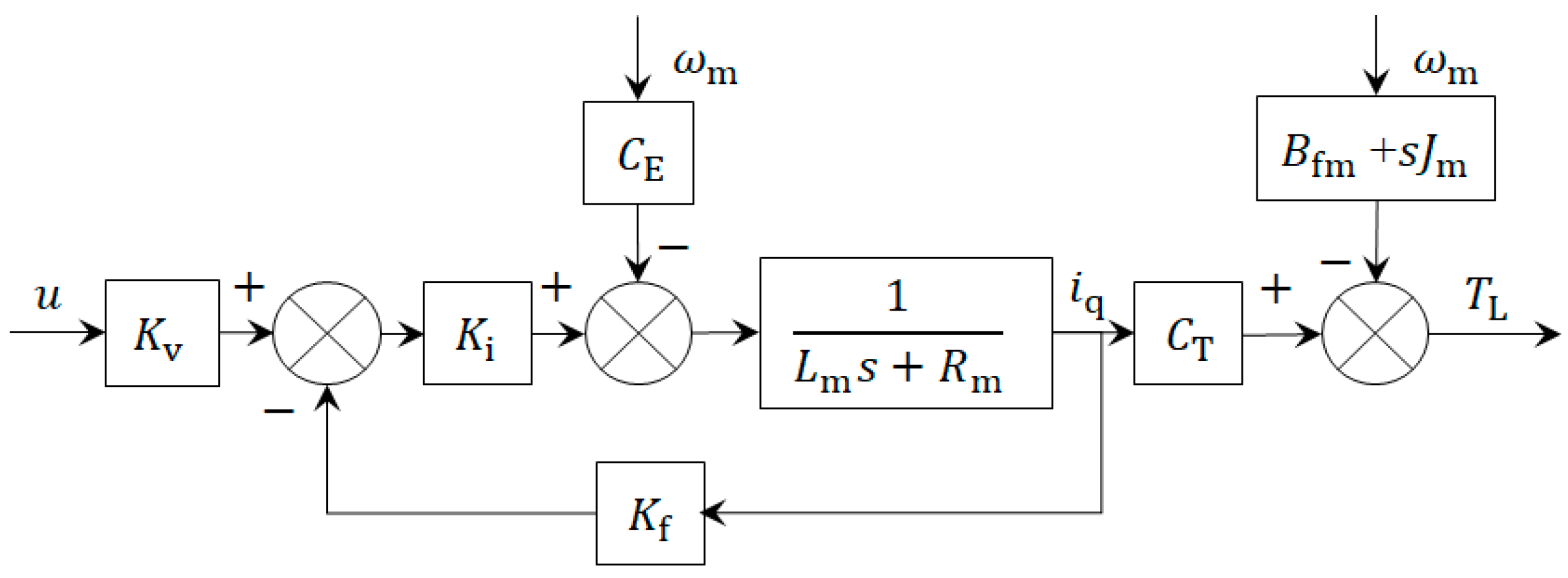
Taking the Laplace transform of Equations (1) and (2), a transfer function with TL as the output and u and θm as inputs can be obtained as follows:
T L = K i K v C T u C E C T ω m s L m + R m + K i K f ( B fm + s J m ) ω m
The open-loop system model block diagram of the PMSM is shown in Figure 2.

3.2. Planetary-Roller Screw Pair

Considering the nonlinear friction torque, the force analysis equation of the screw pair can be obtained as follows:
F n = m ema x ¨ ema + B fr x ˙ ema + F ema
Based on the conversion relationship between linear and rotary motions, the motion equation of the planetary-roller screw pair can be obtained as follows:
F n = η ema k ema T L R = η ema 2 π P rs T L R
Taking the Laplace transform of Equations (4) and (5), a transfer function with xema as the output and TL and Fema as inputs can be obtained as follows:
x ema = η ema k ema T L R F ema s ( s m ema + B fr )
The model is not specific to the roller-screw type, but is instead general. Equations (5) and (6) are written in the case of an opposite load, and for simplification the case of an aiding load is not considered, although the EMA works in both cases.
The open-loop system model block diagram of the planetary-roller screw pair is shown in Figure 3.

3.3. Force Sensor

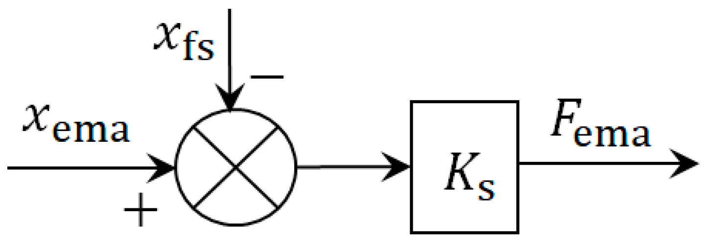
Since the force sensor has very small inertia and operates within the range of elastic deformation, the force analysis equation of the force sensor can be obtained as follows:
F ema = K s ( x ema x fs )
Thus, the open-loop system model block diagram of the force sensor is shown in Figure 4.

3.4. Load Connection Point

In order to make the model more perfect, the inertial load is selected in the mathematical model; the mass of the inertial load is 0.001 kg, which is equivalent to no load.
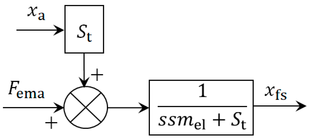
Considering the connection stiffness between the LEMA and the load connection point, the force analysis equation at the load connection point can be obtained as follows:
F ema = m el x ¨ ema + S t ( x ema x a )
Thus, the open-loop system model block diagram at the load connection point is shown in Figure 5.

4. Anti-Disturbance Control Strategy for the Force Servo System

4.1. Establishment of an Open-Loop Model of the Force Servo System

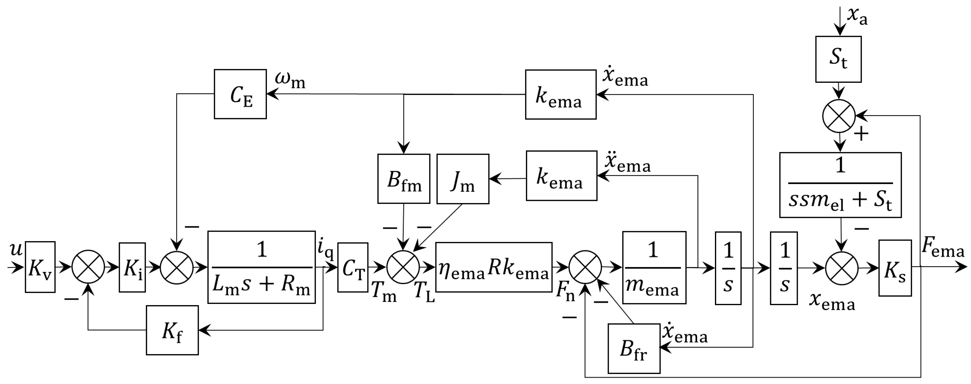
Based on the model block diagrams of each core component, an open-loop model block diagram of the force servo system with the input command u and the external position disturbance xa as inputs and Fema as the output can be obtained, as depicted in Figure 6. Its open-loop transfer function is expressed as follows:
F ema = R k ema η ema K i K v C T u s F ab ( F ema K s + F ema + S t x a s 2 m el + S t ) s L m + R m + K i K f
where Fab can be obtained as follows:
F ab = { R k ema 2 η ema C T C E + ( B fm + s J m ) ( s L m + R m + K i K f ) + ( s m ema + B fr ) ( s L m + R m + K i K f ) }

4.2. Design of the Force Servo System Controller

Compared with GEMAs, DEMAs lack an internal reducer, resulting in a larger equivalent moment of inertia from the system’s output end to the motor’s output end. Furthermore, due to the smaller system damping of DEMAs, the force servo system exhibits poor stability without the addition of a compensation link.
In this study, an EXLAR GSX40-1801 DEMA was chosen to discuss and analyze the control strategy and performance of the EMA force servo system. The GSX40-1801 model boasts a rated output force of 17.6 kN, a maximum speed of 127 mm/s, a maximum stroke of 457 mm, and a screw lead of 2.54 mm. Detailed parameters of this EMA can be found on EXLAR’s official website and thus are not elaborated herein [47].
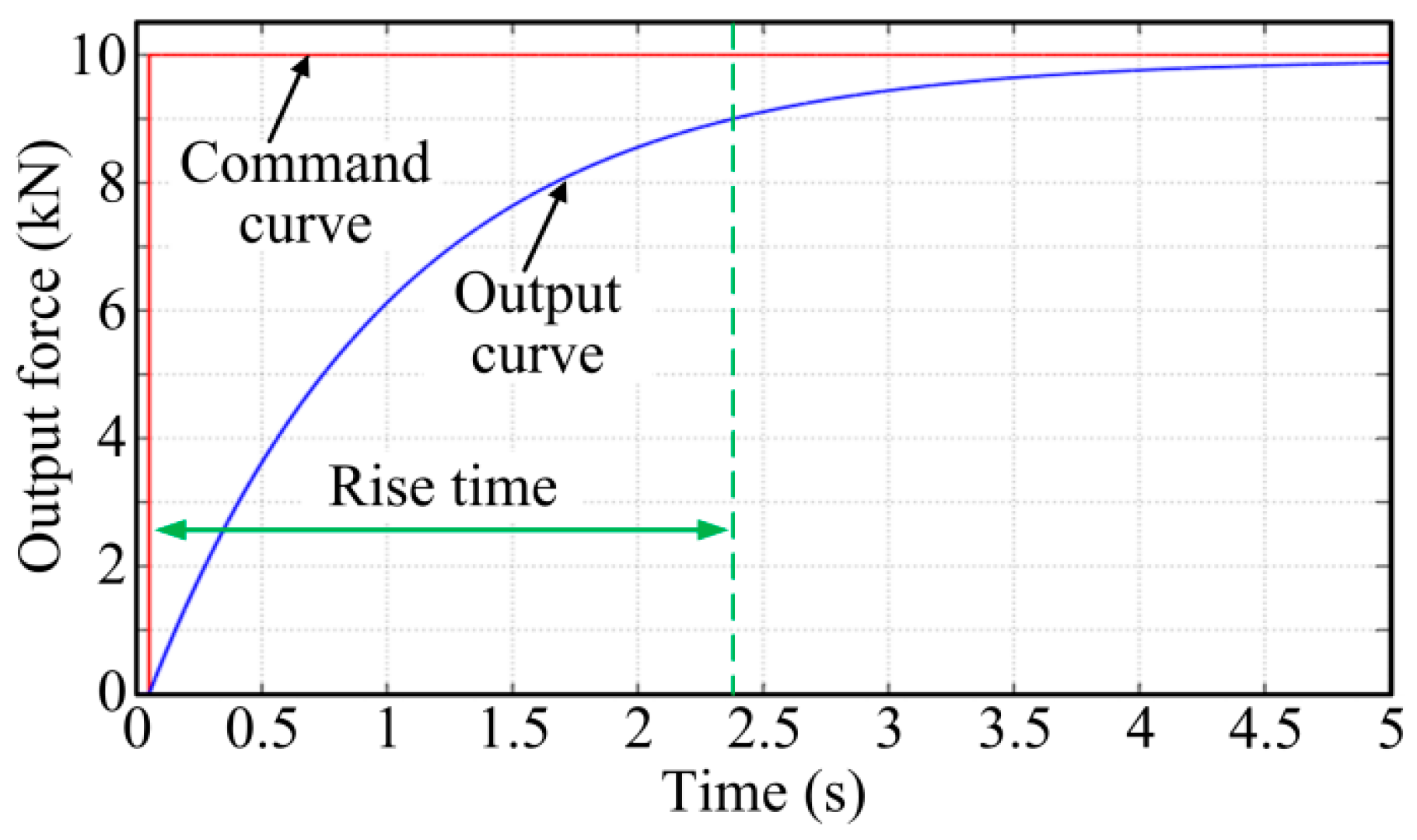
The stability of the closed-loop control system is crucial in the control system design. According to control theory, the introduction of speed feedback can increase the system’s damping ratio, thereby enhancing its stability. After the introduction of speed feedback with no control parameters added (even the P controller), and given a step command of 10 kN, a response curve of the DEMA system was obtained (as depicted in Figure 7), with a rise time of 2.3 s and a steady-state error of 477 N (4.77%). This indicated that appropriately introducing speed feedback could increase the damping of the DEMA system and improve its stability. However, as can be seen in Figure 7, the DEMA at this moment showed poor rapidity and response speed.
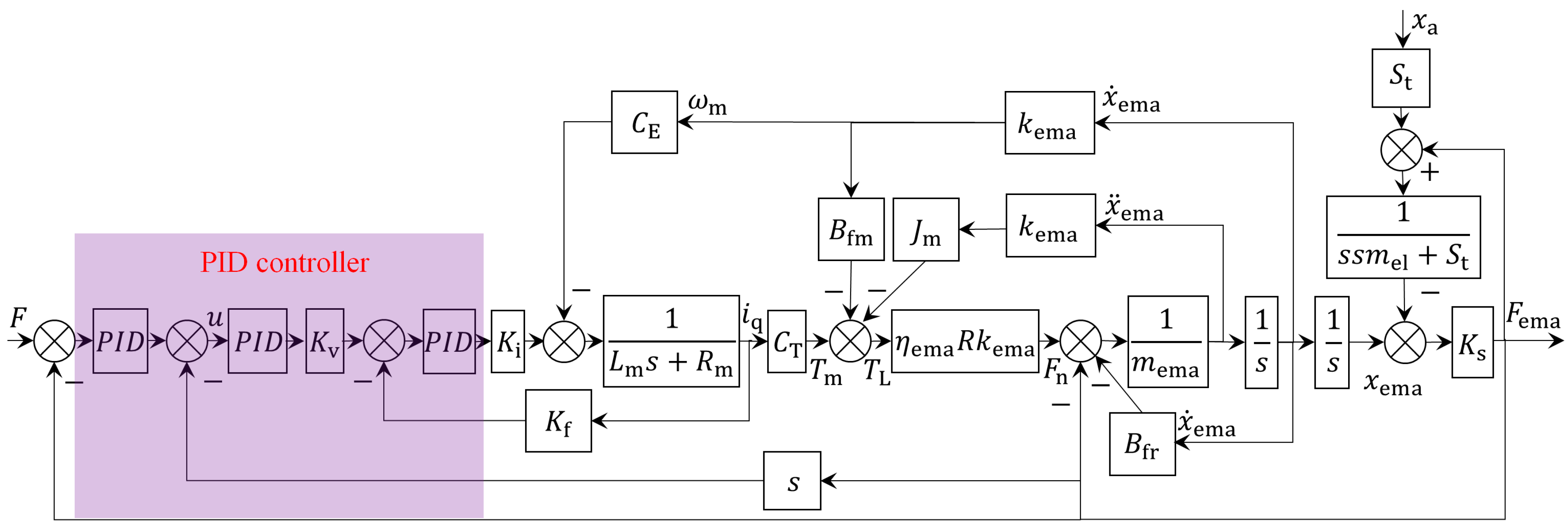
To further improve the tracking accuracy and rapidity of the DEMA system, a PID controller, recognized for its straightforward algorithm, high reliability, and wide applicability, was introduced on the basis of speed feedback. The system block diagram after the introduction of a PID controller is shown in Figure 8.
Amesim is a simulation platform capable of building precise and complex system models across various disciplines and domains. Its application in engineering has been widely recognized by professionals in fields such as aviation, aerospace, navigation, and the automotive industry. In this study, a simulation model of the DEMA force servo system was built in Amesim based on the mathematical model, and a simulation analysis was then performed, aiming to replicate the input–output characteristics of the DEMA system to the greatest extent and to verify the control strategy.
In the simulation of sweep characteristics, 10–20% of the EMA’s rated output is generally taken. The GSX40-1801 model boasts a rated output force of 17.6 kN, so 2 kN is taken as an example for simulation analysis.
Under the condition of no external position disturbance input, a performance simulation analysis was conducted on the DEMA system introduced with a PID controller. Details are as follows:
(1)
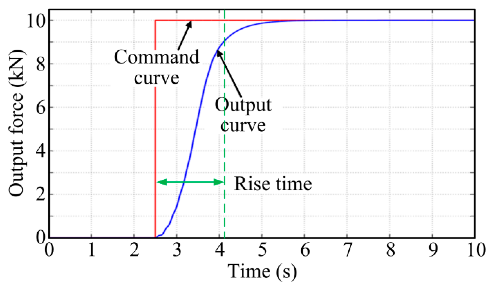
Given a step command of 10 kN, a response curve of the DEMA system was obtained (as shown in Figure 9), with a rise time of 1.6 s and a steady-state error of 3 N (0.03%). It is worth mentioning that this result is relatively ideal. For actual EMA systems, such high control accuracy would not be possible due to sensor testing errors and nonlinear friction.
(2)
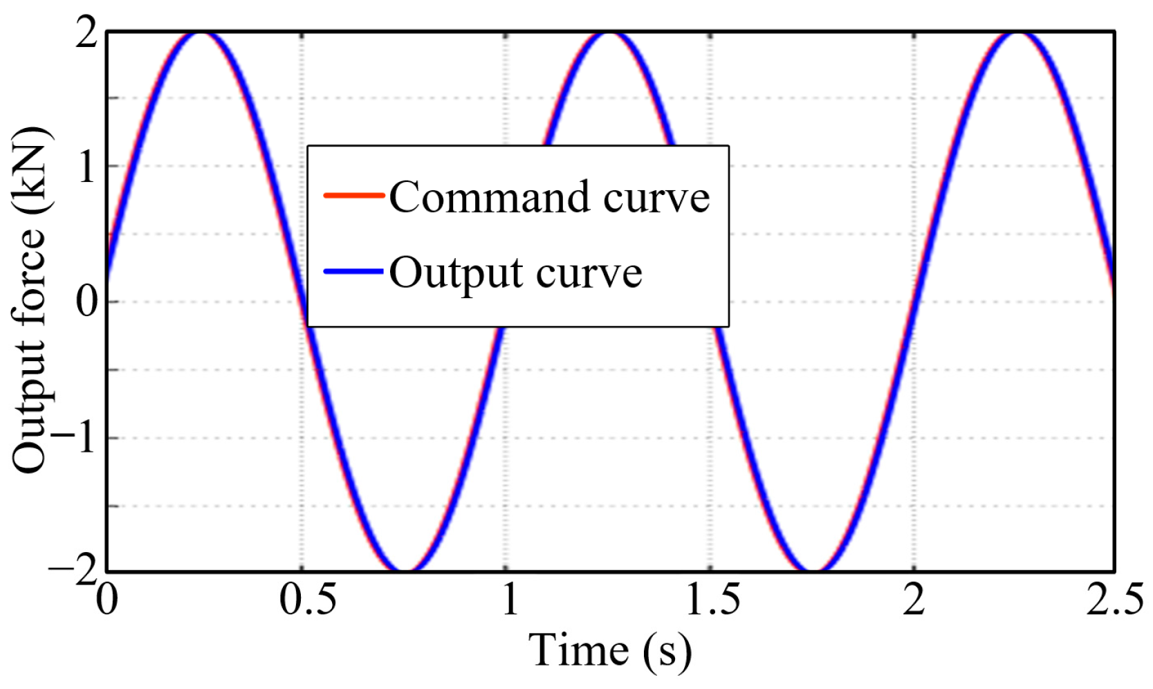
Given a sinusoidal command with an amplitude of 2 kN and a frequency of 1 Hz, a response curve of the DEMA system was obtained (as shown in Figure 10), wherein the input curve and the output curve almost completely overlapped, with a tracking error of 63 N (3.15%).
(3)
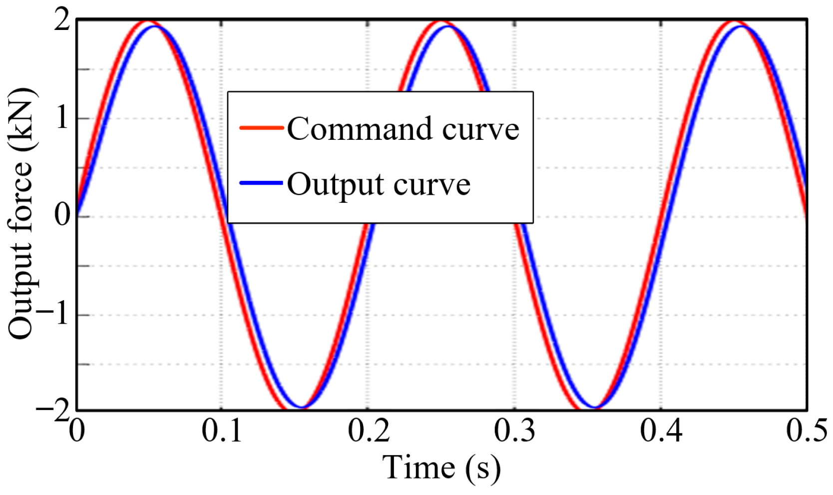
Given a sinusoidal command with an amplitude of 2 kN and a frequency of 5 Hz, a response curve of the DEMA system was obtained (as shown in Figure 11), wherein the overlap between the input curve and the output curve was relatively high, with a tracking error of 300 N (15%).
(4)
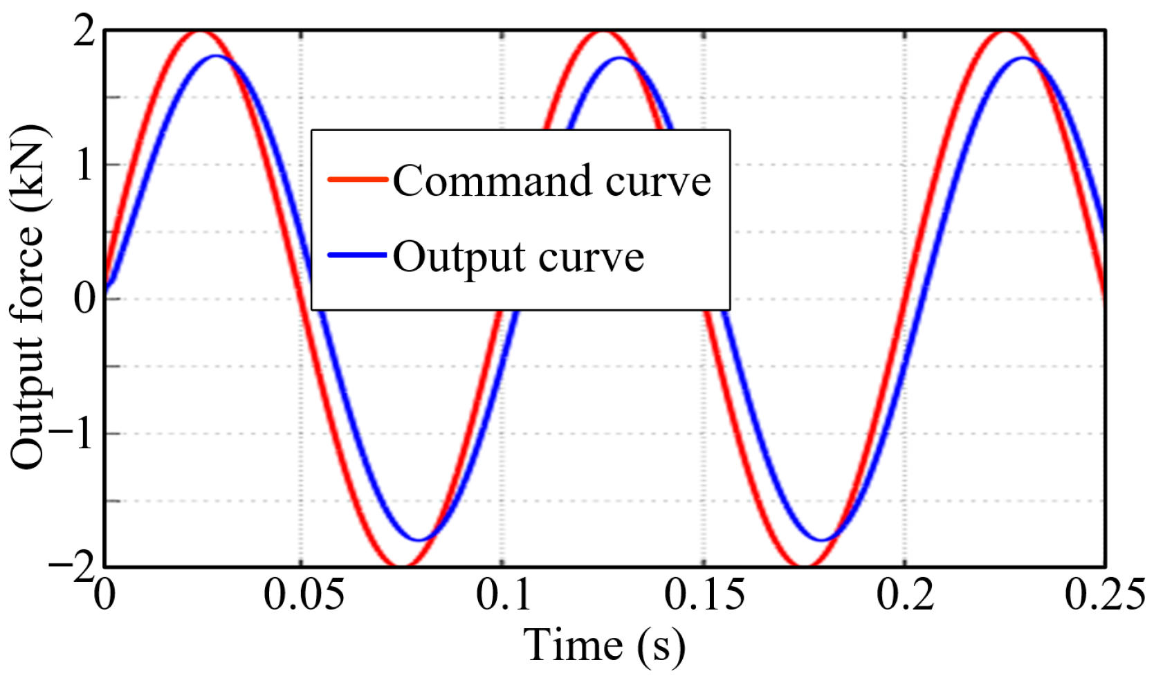
Given a sinusoidal command with an amplitude of 2 kN and a frequency of 10 Hz, a response curve of the DEMA system was obtained (as shown in Figure 12), wherein the overlap between the input curve and the output curve was slightly poor, with a tracking error of 550 N (27.5%).
These simulation results demonstrated that the PID control method was simple and practical, which could improve the dynamic characteristics of the system and enhance its response speed and tracking accuracy. Nevertheless, the tracking accuracy of the DEMA system gradually decreased as the frequency of the command signal increased.

4.3. Design of a Force Servo System Controller to Overcome External Position Disturbances

The end position of the EMA force servo system changes as the position of the loaded object changes. This change in the end position generates disturbance forces on the EMA, thereby badly affecting the accuracy and dynamic performance of the force servo system. Therefore, the force servo system should suppress disturbance forces to the greatest extent possible. In other words, the EMA force servo system should have sufficient anti-disturbance capability, rapidity, and loading accuracy.
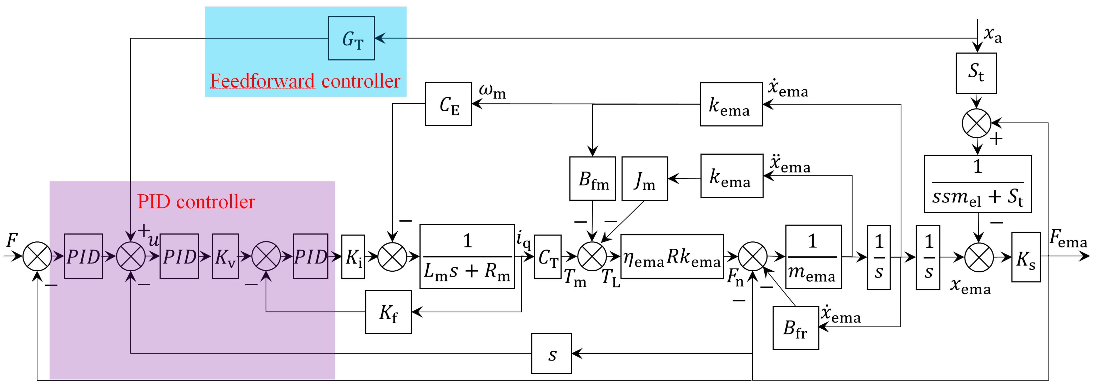
In this study, drawing on the principle of structure invariance, a relatively complex high-order transfer function GT associated with various parameters such as speed and acceleration was added as feedforward compensation to xa, so as to suppress the impact of external position disturbances on the system’s motion performance. The system model block diagram with the feedforward correction element added is shown in Figure 13.
Since the stiffness Ks of the force sensor is normally taken as 5 × 10⁷ N/m, much larger than the connection stiffness St between the LEMA and the load connection point, the effect of the stiffness Ks of the force sensor on the system’s stability and dynamic characteristics can be neglected when calculating the controller parameters [45]. It can be approximated as a rigid connection, and thus the open-loop transfer function of the force servo system can be simplified as follows:
F ema = R k ema η ema K i K v C T u s F ab F ema + S t x a s 2 m el + S t s L m + R m + K i K f = ( s 2 m el + S t ) R k ema η ema K i K v C T u ( F 3 s 3 + F 2 s 2 + F 1 s ) x a G 3 s 3 + G 2 s 2 + G 1 s + G 0
where:
F 3 = S t ( L m m ema + R J m L m η ema k ema 2 )
F 2 = S t [ η ema k ema 2 R ( J m R m + J m K i K f + B fm L m ) + B fr L m + m ema ( R m + K i K f ) ]
F 1 = S t [ η ema k ema 2 R ( C T C E + B fm R m + K i K f B fm ) + B fr ( R m + K i K f ) ]
G 3 = L m m ema + m el L m + J m L m η ema k ema 2 R
G 2 = η ema k ema 2 R ( J m R m + J m K i K f + B fm L m ) + B fr L m + ( m ema + m el ) ( R m + K i K f )
G 1 = η ema k ema 2 R ( C T C E + B fm R m + K i K f B fm ) + B fr ( R m + K i K f ) + S t L m
G 0 = S t ( R m + K i K f )
By dividing both the numerator and the denominator on the right side of Equation (11) by the coefficient of u, we obtain:
F ema = u ( F 3 s 3 + F 2 s 2 + F 1 s ) x a ( s 2 m el + S t ) R k ema η ema K i K v C T [ ( s 2 m el + S t ) R k ema η ema K i K v C T ] ( G 3 s 3 + G 2 s 2 + G 1 s + G 0 )
It can be seen from Figure 13 that to suppress the disturbance force, the feedforward correction element should be used to counteract the part following u in the numerator of Equation (12):
G T = F 3 s 3 + F 2 s 2 + F 1 s ( s 2 m el + S t ) R k ema η ema K i K v C T
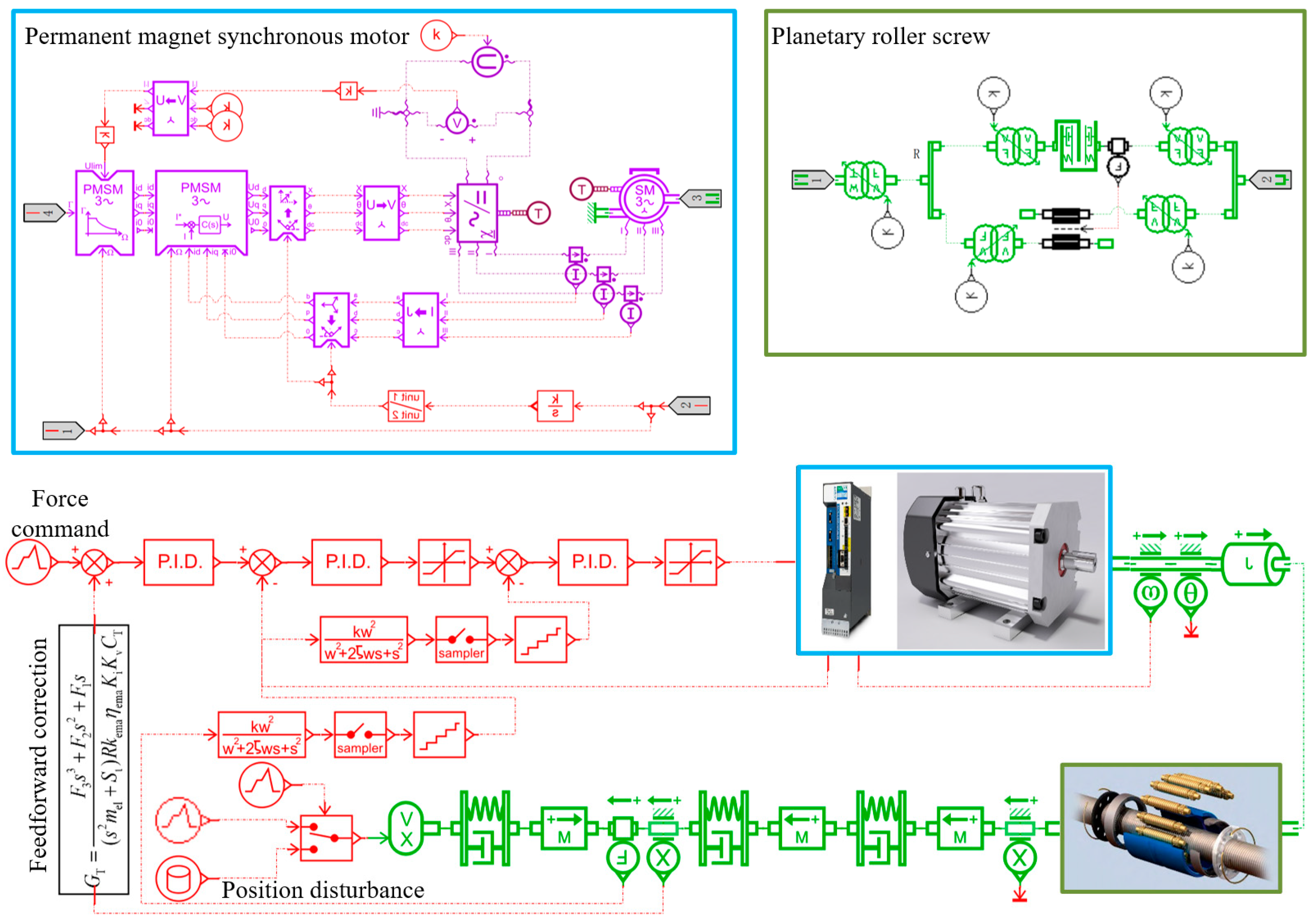
The simulation model of the DEMA force servo system introduced with a PID controller and a feedforward correction element is shown in Figure 14 [48,49,50].
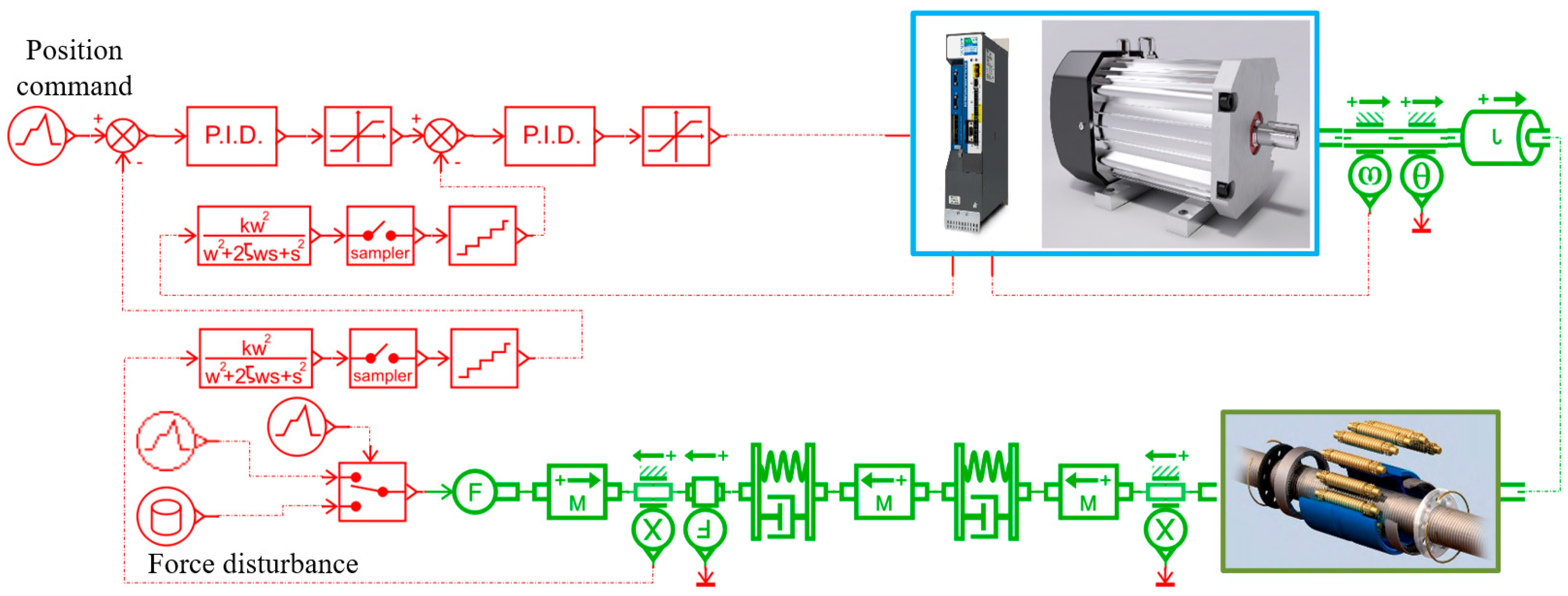
As shown in Figure 14, we added several modules in the model to simulate the sampling and data processing of the processor, making the simulation model more realistic. In order to make the simulation model easier to understand and operate, we use PMSM and planetary-roller screw pairs as super components, and integrate feedforward and its sampling and data processing into the super components.
The disturbance of the force servo system is mainly divided into static position disturbance and dynamic position disturbance.
For the simulation model, the current-loop parameters P and I are auto-tuned through the PMSM module (as shown in Figure 14) in the servo motor model. The method for obtaining the PID parameters of the speed and position loops is as follows: First, a set of usable PID parameters is obtained using the most commonly used Ziegler–Nichols method in engineering applications. Then, the parameters are refined in the nearby parameter space based on Amesim, and one of the optimal sets of parameters is selected for simulation.
In this section, the PID parameters selected for the speed loop are 10 rpm/N, 0 rpm/(N·s), and 0.1 (rpm·s)/N, while the PID parameters selected for the position loop are 900 rpm/N, 0.3 rpm/(N·s), and 0 (rpm·s)/N, respectively.
Under the conditions of an external position disturbance signal with an amplitude of 10 mm and a frequency of 5 Hz, a performance simulation analysis was conducted on the DEMA system introduced with a PID controller and a feedforward correction element. Details are as follows:
(1)
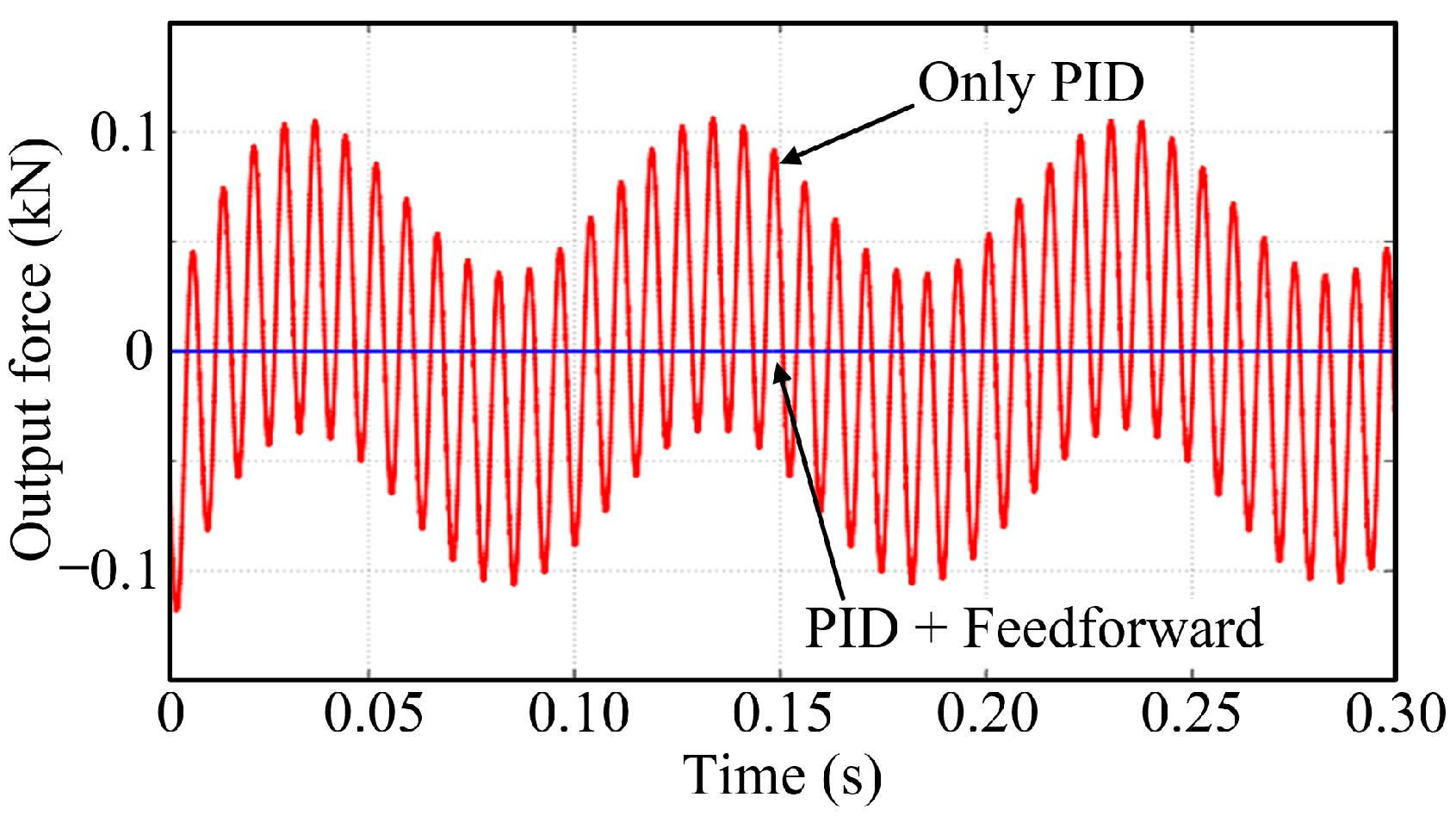
Given a motion command of 0 kN, a response curve of the DEMA system was obtained (as shown in Figure 15), wherein the system with the feedforward correction element added significantly weakened the disturbance force, with an output force of approximately 2 × 10⁻¹⁰ kN.
(2)
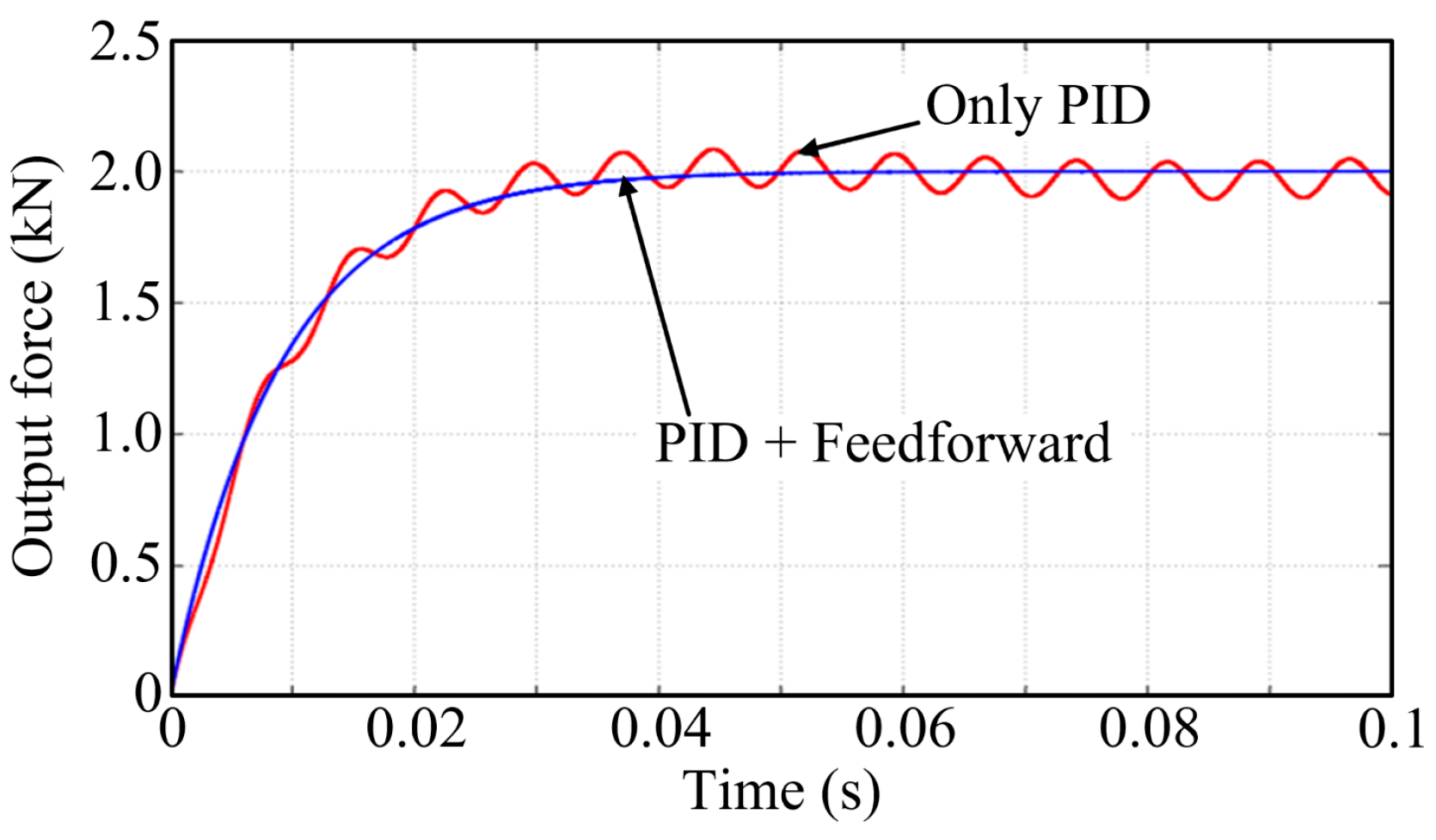
Given a step command of 2 kN, a response curve of the DEMA system was obtained (as shown in Figure 16), wherein the system with the feedforward correction element added exhibited a smooth output curve without jitter.
(3)
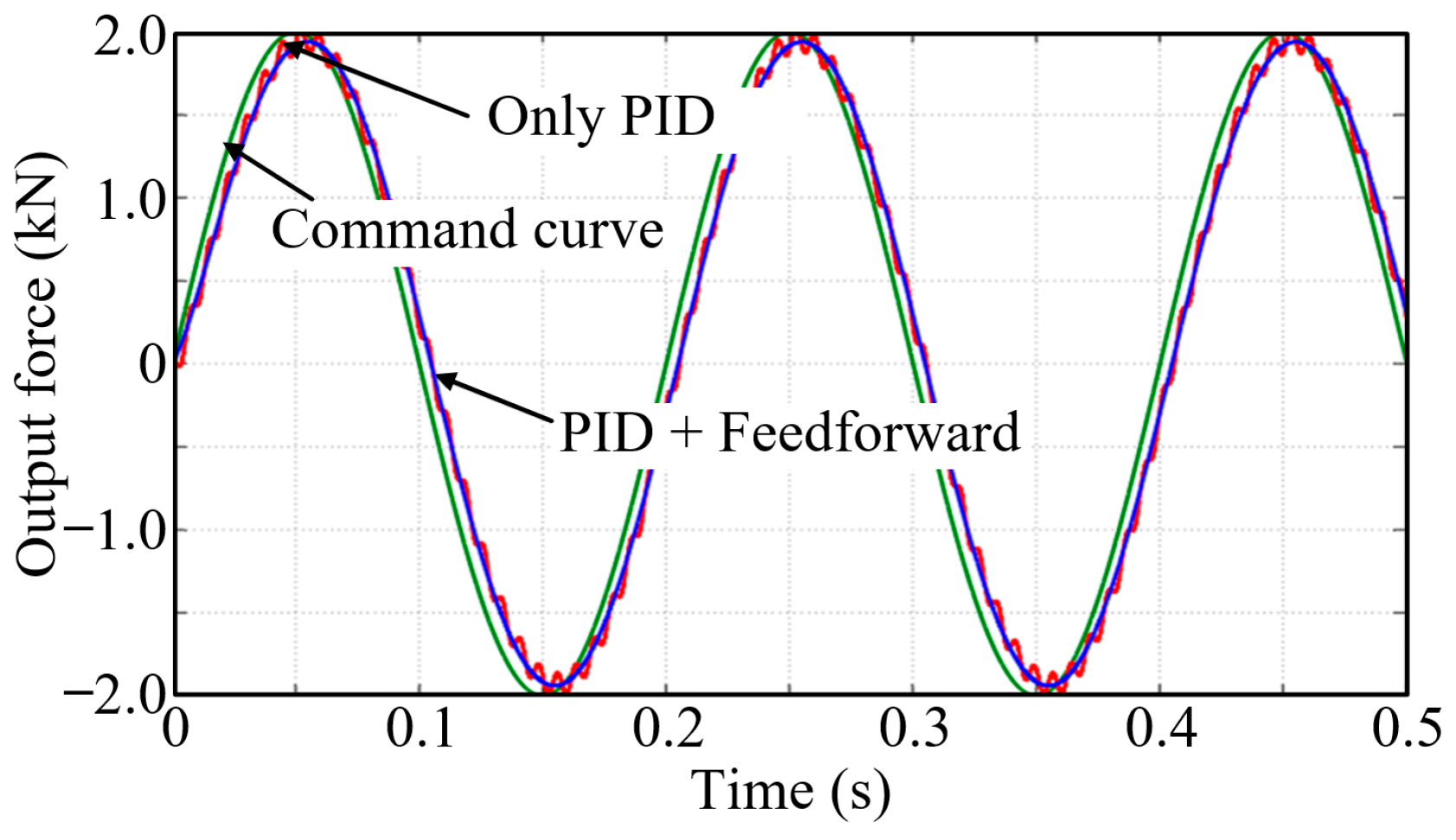
Given a sinusoidal command with an amplitude of 2 kN and a frequency of 5 Hz, a response curve of the DEMA system was obtained (as shown in Figure 17), wherein the system with the feedforward correction element added exhibited a smooth output curve without jitter, with a tracking error of 300 N (15%).
(4)
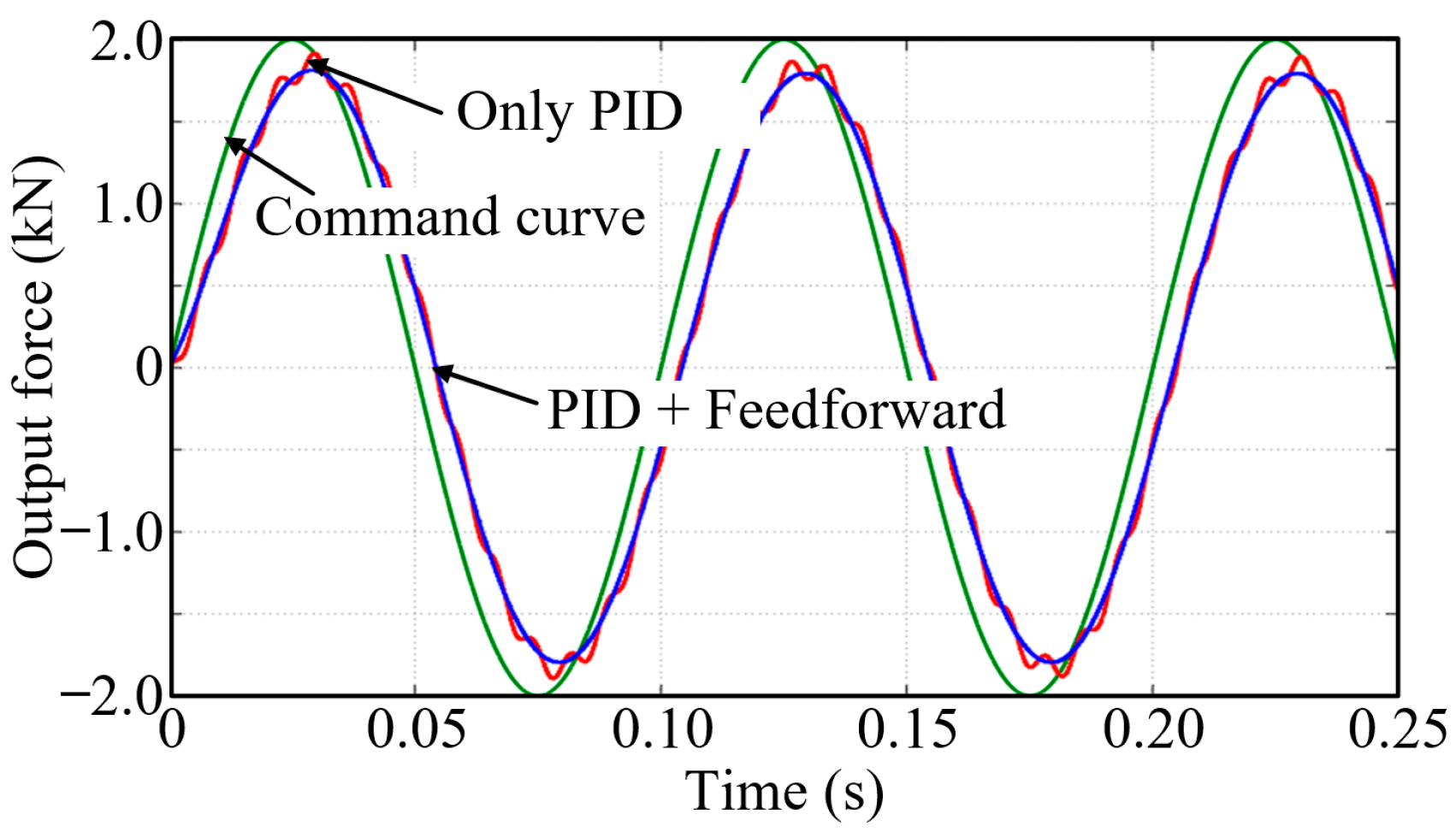
Given a sinusoidal command with an amplitude of 2 kN and a frequency of 10 Hz, a response curve of the DEMA system was obtained (as shown in Figure 18), wherein the system with the feedforward correction element added exhibited a smooth output curve without jitter, with a tracking error of 550 N (27.5%).
Through comparative analysis, it can be seen that under the condition of an external position disturbance signal of 10 mm at 5 Hz, the motion accuracy and dynamic performance of the DEMA force servo system introduced with a composite controller (consisting of a PID controller and a feedforward correction element) were almost unaffected by the external position disturbance. Nevertheless, the tracking accuracy of the DEMA system decreased as the frequency of the command signal increased.

5. Anti-Disturbance Control Strategy for Position Servo System

5.1. Establishment of an Open-Loop Model of the Position Servo System

Since no force sensor is needed at the end of the position servo system, based on the model block diagrams of each core component, an open-loop model block diagram of the position servo system with u and the external disturbance force Fema as inputs and xema as the output can be obtained, as depicted in Figure 19. Its open-loop transfer function is expressed as follows:
x ema = R k ema η ema K i K v C T u ( s L m + R m + K i K f ) F ema s ( s m ema + B fr ) ( s L m + R m + K i K f ) + s R k ema 2 η ema ( K i K v C T C E + B fm + s J m )

5.2. Design of the Position Servo System Controller

In this study, an EXLAR FT35-1805 GEMA with a faster motion velocity was chosen to describe and analyze the control strategy and performance of the EMA position servo system. The FT35-1805 model boasts a rated output force of 17.8 kN, a maximum speed of 373 mm/s, a maximum stroke of 457 mm, and a screw lead of 5 mm. Detailed parameters of this EMA can be found on EXLAR’s official website and are thus not elaborated herein [47].
Like the force servo system, the introduction of speed feedback can also increase the damping ratio of the EMA position servo system, thereby enhancing its stability. Additionally, the introduction of a PID controller can further improve the system’s tracking accuracy and rapidity. A simulation model of the GEMA position servo system was built in Amesim based on the mathematical model, as shown in Figure 20, so as to verify the performance and control strategy of the GEMA.
The disturbance of the position servo system can be divided into static force disturbance and dynamic force disturbance.
In this section, the PID parameters selected for the speed loop are 30 rpm/m, 1 rpm/(m·s), and 3 (rpm·s)/m, while the PID parameters selected for the force loop are 10 rpm/m, 3 rpm/(m·s), and 0 (rpm·s)/m, respectively.
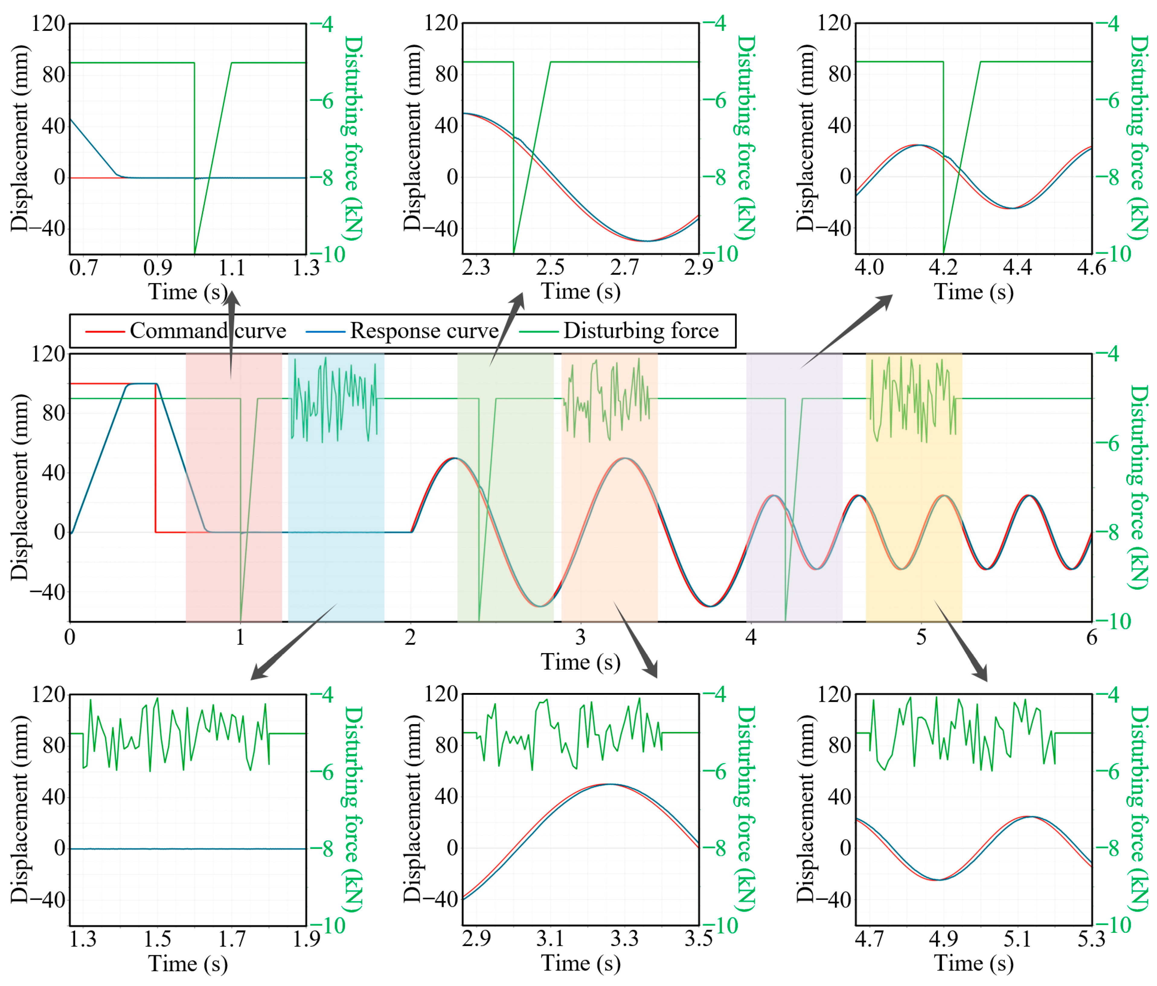
A load force of 5 kN was applied to the GEMA system, and under the conditions of a step command of 100 mm, a sinusoidal command of ±50 mm at 1 Hz, and a sinusoidal command of ±25 mm at 2 Hz, a performance simulation analysis was conducted on the GEMA system with an impact force of 5 kN and a random disturbance force within the range of ±1 kN added. The response curve is shown in Figure 21.
(1)
Under the condition of no disturbance force, the rise time of the 100 mm step response was 0.3 s, and the system exhibited a smooth output curve without steady-state error; for the response to the sinusoidal command of ±50 mm at 1 Hz, the output curve was smooth, with a tracking error of 4.2 mm (8.4%); for the response to the sinusoidal command of ±25 mm at 2 Hz, the output curve was smooth, with a tracking error of 3.8 mm (15.2%).
(2)
Under the condition of a random disturbance force within the range of ±1 kN, the accuracy and dynamic performance of the step response and sinusoidal response were almost unaffected, and the system exhibited a smooth output curve with almost no jitter.
(3)
Under the condition of an impact force of 5 kN, the output curves of the step response and sinusoidal response fluctuated slightly, and subsequently, the system immediately recovered to a dynamic steady state.
These simulation results indicated that under multiple external disturbance forces, the motion accuracy and dynamic performance of the GEMA position servo system introduced with a PID controller were almost unaffected. Nevertheless, the tracking accuracy of the GEMA system decreased as the frequency of the command signal increased.

6. Building of the Test Bed and Analysis of the Test Data

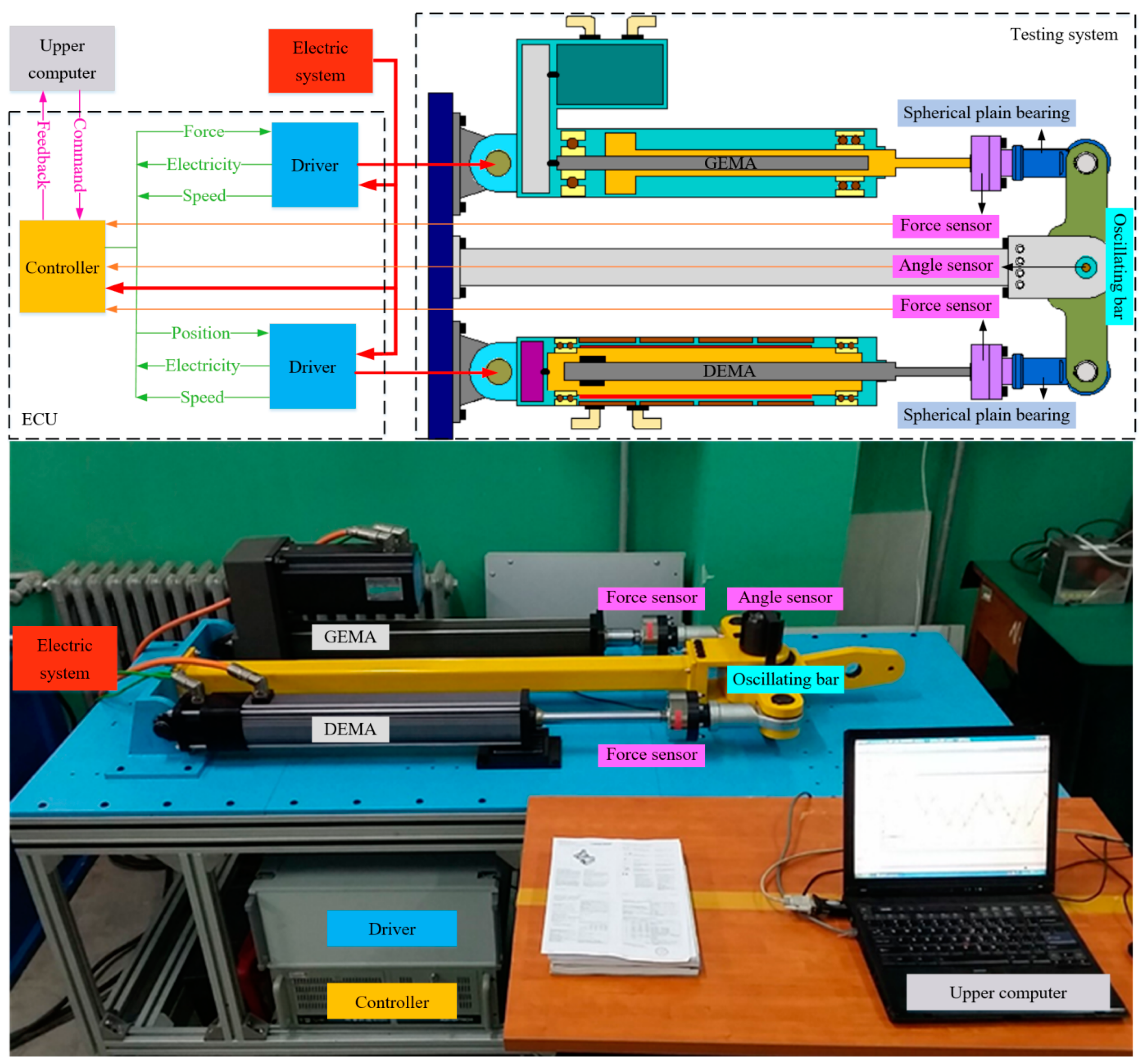
To further test the dynamic performance of the EMA, verify the anti-disturbance control strategy for the single-channel EMA, and lay the foundation for subsequent research on dual-channel synchronous control strategies, a dual-channel EMA performance testing system was built for this study, which consists of an electronic control unit (ECU) and a testing system.
As shown in Figure 22, the testing system comprises a GEMA, a DEMA, a force sensor, an angle sensor, joint bearings, and mounting components. The ECU consists of an upper computer, a controller, a driver, and an electric system. Specifically, the upper computer is used for writing control programs, monitoring system status, and outputting control commands, along with data acquisition, processing, and storage; the controller is used to resolve the control commands from the upper computer and outputs them to the driver, while also collecting and processing EMA operating state signals (e.g., position, speed, current) and reporting them to the upper computer; the driver is used for power supply, data transmission, and current-loop control for the EMA; and the electric system is used for power supply and distribution.

6.1. Static Anti-Disturbance Test

This section tests the anti-disturbance performance of the EMA under static conditions, and the tracking error and vibration amplitude are used as indicators to measure the anti-jamming performance.
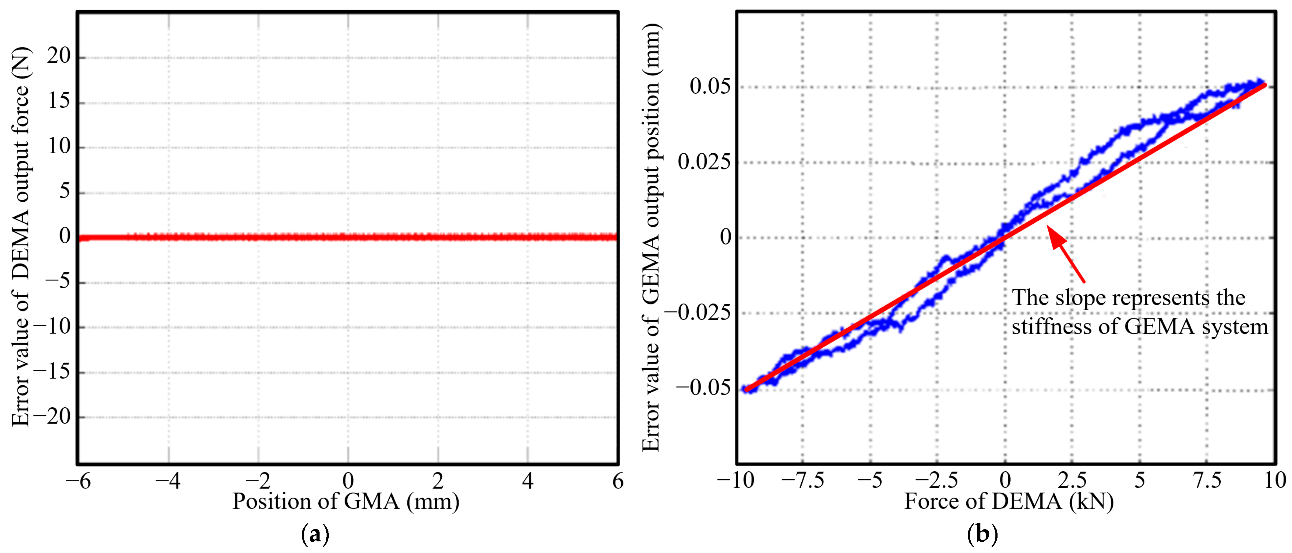
To verify the anti-disturbance control strategy for the force servo system, the DEMA was used as a loaded cylinder and operated in a force closed-loop mode, while the GEMA was used as a loading cylinder and operated in a position closed-loop mode. The GEMA was given a −6 mm~+6 mm slowly changing position control command as the DEMA’s external position interference, and the DEMA was given a constant output command of 10 kN for force closed-loop control.
The error curve of the DEMA output force measured by the test is shown in Figure 23a. The DEMA can maintain a constant output force of 10 kN with maximum error of no more than 5 N under the condition of external position interference of ±5 mm. In other words, under static conditions, the DEMA force servo system has high robustness and good anti-disturbance characteristics.
To verify the anti-disturbance control strategy for the position servo system, the GEMA was used as a loaded cylinder and operated in a position closed-loop mode, while the DEMA was used as a loading cylinder and operated in a force closed-loop mode. The DEMA was given a slowly changing output force signal of −10 kN~+10 kN as the external interference force of the GEMA, and the GEMA was given a constant output command of 0 mm for position closed-loop control.
The error curve of the GEMA output position measured by the test is shown in Figure 23b. Under the condition of −10 kN~+10 kN~−10 kN external force interference, the GEMA can maintain a constant output command of 0 mm, and the error is no more than 0.06 mm. In other words, under static conditions, the GEMA position servo system has high robustness and good anti-disturbance characteristics. Additionally, it is not difficult to calculate from the test data that the closed-loop stiffness of the GEMA system is about 2 × 10⁸ N/m.

6.2. Dynamic Anti-Disturbance Test

This section tests the anti-disturbance performance of the EMA under dynamic conditions, and the tracking error and vibration amplitude are used as indicators to measure the anti-jamming performance.
To verify the anti-disturbance control strategy for the force servo system, the GEMA was given a sinusoidal command of 5 mm at 5 Hz as an external position disturbance for the DEMA, and the DEMA was given a sinusoidal command of 5 kN at 3 Hz for force closed-loop control.
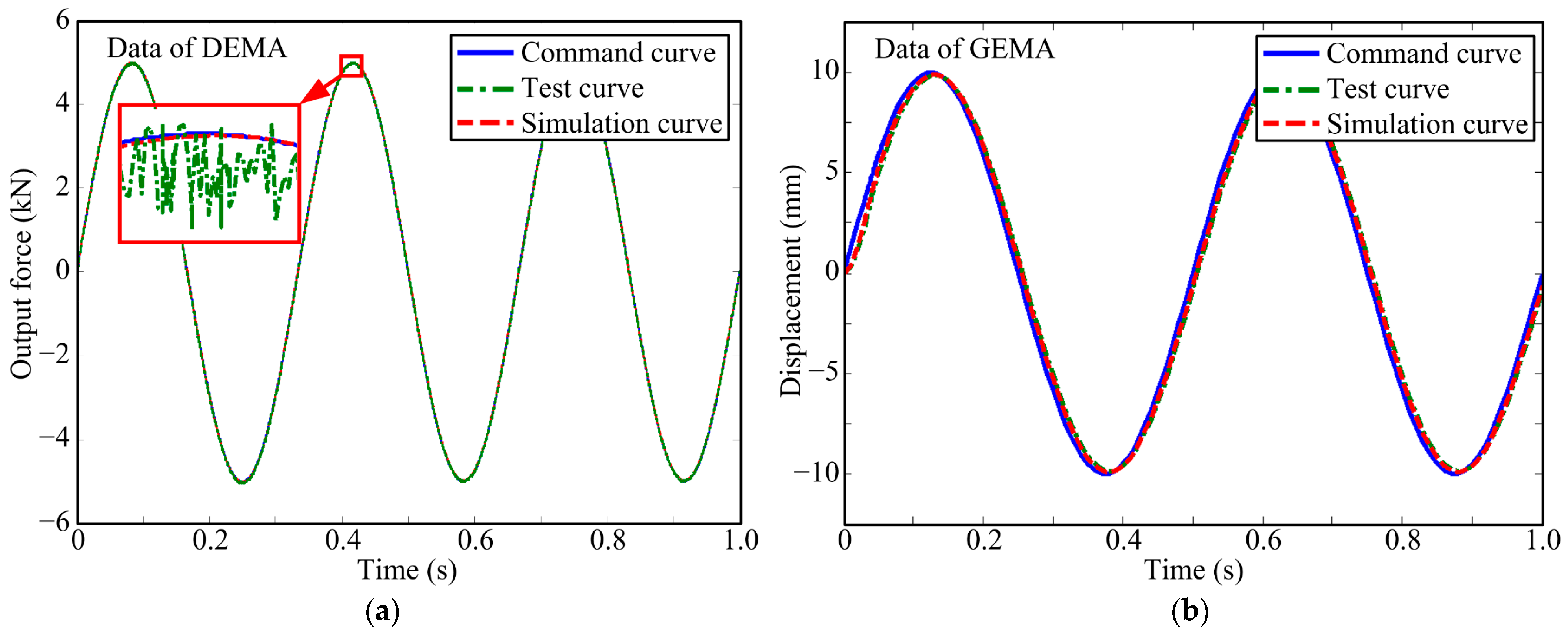
The DEMA data are shown in Figure 24a. Under the condition of an external position disturbance of 5 mm at 5 Hz, the DEMA system introduced with a composite controller (consisting of a PID controller and a feedforward correction element) exhibited a smooth simulation curve with no jitter and almost no tracking error. This indicated that the motion accuracy and dynamic performance of the DEMA force servo system were almost unaffected by the external position disturbance. The variation trend in the test curve integrated well with that of the simulation curve, with minimal tracking error, thus verifying the correctness of the anti-disturbance control strategy for the force servo system. However, compared with the simulation curve, the test curve exhibited a small range of high-frequency jitter, approximately ±30 N (0.6%), which was caused by factors such as mechanical clearance, stiffness, and sensor testing accuracy.
To verify the anti-disturbance control strategy for the position servo system, the DEMA was given a random disturbance force signal within the range of ±1 kN as an external disturbance force for the GEMA, and the GEMA was given a sinusoidal command of 10 mm at 2 Hz for position closed-loop control.
The GEMA data are shown in Figure 24b. Under the condition of a random disturbance force within the range of ±1 kN, the GEMA system introduced with a PID controller exhibited a smooth simulation curve with no jitter, and the maximum tracking error is about 0.2 mm (2%). This indicated that the motion accuracy and dynamic performance of the GEMA position servo system were almost unaffected by the external disturbance force, and there was no need to adopt the composite control method. The variation trend in the test curve accorded with that of the simulation curve, with small error and no jitter, thus verifying the correctness of the anti-disturbance control strategy for the position servo system.
These results indicated that both the force servo system introduced with a composite controller (consisting of a PID controller and a feedforward correction element) and the position servo system introduced with a PID controller exhibited motion accuracy and dynamic performance that were almost unaffected by external disturbances, and the tracking error and vibration amplitude were small. This verified the correctness of the anti-disturbance control strategy and the accuracy of the simulation model.

7. Conclusions

In this paper, DEMAs and GEMAs were taken as objects of study, and relevant studies were conducted on their mathematical models, anti-disturbance control strategies, and performance tests. The major efforts and significant conclusions are summarized as follows:
(1)
The classification and structural composition of EMAs were introduced first. Then, taking the DEMA and GEMA as objects of study and based on their working principles and connection methods, the basic equations of each core component were derived, the mathematical models were established for the force servo system and the position servo system, and the performance simulation models of core components and servo systems were built in Amesim. These efforts laid a solid foundation for the study of control strategies.
(2)
Under the condition of no external position disturbance, the DEMA force servo system introduced with a PID controller exhibited good motion accuracy and dynamic performance. However, under the condition of an external position disturbance signal of 10 mm at 5 Hz, the output curve of the DEMA force servo system fluctuated significantly, severely impacting the system performance.
(3)
Drawing on the principle of structure invariance and the mathematical model, a relatively complex high-order transfer function GT associated with various parameters such as speed and acceleration was derived and obtained as feedforward compensation, so as to suppress the impact of external position disturbances on the performance of the force servo system. Simulation results indicated that the DEMA force servo system introduced with a composite controller (consisting of a PID controller and a feedforward correction element) exhibited good anti-disturbance capability, rapidity, and loading accuracy, the output curve was smooth without jitter, and the system performance was almost unaffected by external position disturbances.
(4)
Speed feedback was introduced to increase the damping ratio of the position servo system, thereby enhancing its stability. Additionally, the tracking accuracy and rapidity of the position servo system were further improved by introducing a PID controller. Simulation results indicated that under the condition of no disturbance force, the GEMA position servo system exhibited good dynamic performance, while under multiple external disturbance forces, the motion accuracy and dynamic performance of the GEMA position servo system introduced with a PID controller were almost unaffected, and there was no need to adopt the composite control method (i.e., PID controller + feedforward correction element).
(5)
A dual-channel EMA performance testing system was developed based on the DEMA and GEMA, which consists of an ECU and a testing system. The static and dynamic anti-jamming tests were carried out. The experimental results show that the DEMA force servo system and the GEMA position servo system have high robustness and good anti-disturbance characteristics, and the tracking error and vibration amplitude are small. The test results were basically consistent with the simulation results, which verified the correctness of the single-channel EMA anti-disturbance control strategy and the availability of the simulation model and laid a solid foundation for subsequent research on dual-channel synchronous control strategies.

Author Contributions

Conceptualization, S.Z., J.Z. and Y.Y.; methodology, S.Z. and D.W.; software, S.Z. and J.W.; validation, S.Z., J.Z. and Y.Y.; formal analysis, S.Z., D.W. and J.W.; investigation, J.Z. and Y.Y.; resources, J.Z. and Y.Y.; data curation, S.Z., D.W. and J.W.; writing—original draft preparation, S.Z., D.W. and J.W.; writing—review and editing, S.Z., J.Z. and Y.Y.; supervision, J.Z. and Y.Y.; project administration, J.Z. and Y.Y.; funding acquisition, J.Z. and Y.Y. All authors have read and agreed to the published version of the manuscript.

Funding

This work was supported the National Natural Science Foundation of China (grant numbers 62203259, 62073185, and 61903216).

Informed Consent Statement

Not applicable.

Data Availability Statement

The dataset that supports the central findings of this study is directly available in this article. Additional data can be requested from the corresponding author.

Conflicts of Interest

The authors declare no conflicts of interest.

Abbreviations

ParameterDefinitionParameterDefinition
idd-axis current (A)KiCurrent control gain (Nm/A)
iqq-axis current (A)KfCurrent feedback coefficient (–)
RmMotor phase resistance (Ω)KvGain coefficient of q-axis (A/V)
LmInductance in the d-axis and q-axis (mH)CEBack-EMF coefficient (V·s/rad)
uInput signal (V)CTMotor torque constant (N·m/A)
JmMoment of inertia of motor rotor (kg·m2)TmMotor electromagnetic torque (Nm)
ωmAngular velocity of motor rotor (rad/s)TLMotor output torque (Nm)
θmAngle of motor rotor (rad)Td(t)External disturbance torque (Nm)
BfmMotor rotational damping coefficient (Nms/rad)ηemaDirect efficiency of the EMA system (–)
xemaLinear displacement of screw-pair output (m)FnInput force of screw pair (N)
memaMass of screw pair (Kg)FemaOutput force of screw pair (N)
PrsLead of screw pair (m)BfrFriction coefficient of screw pair (N·s/m)
RReduction ratio of reducer (for DEMA takes 1)kemaTransmission ratio of screw pair (1/m)
KsStiffness of the force sensor (N/m)xfsDisplacement of the load (m)
StConnection stiffness (N/m)melLoad mass (Kg)

References

  1. Lu, X.; Liang, J.; Liao, Y. Design of Fault Tolerant Permanent Magnet Motor in Direct Drive Electromechanical Actuator. J. Natl. Univ. Def. Technol. 2011, 33, 134–139. [Google Scholar]
  2. Zhao, J. Design and Research of Displacement-Speed Composite Regulating Electro-Hydrostatic Actuator for Rocket Rudder. Master’s Thesis, Harbin Institute of Technology, Harbin, China, 2014. [Google Scholar]
  3. Li, X. Research on the High-Precision Motion Control Method of Electromechanical Actuator System Based on System Disturbance Adaptive Identification and Suppression. Master’s Thesis, Nanjing University of Science & Technology, Nanjing, China, 2021. [Google Scholar]
  4. Derrien, J.C.; Sécurité, S.D. Electromechanical actuator (EMA) advanced technologies for flight controls. In Proceedings of the 28th International Congress of the Aeronautical Sciences, Brisbane, Australia, 23–28 September 2012; pp. 1–10. [Google Scholar]
  5. Rosero, J.A.; Ortega, J.A.; Aldabas, E.; Romeral, L.A.R.L. Moving towards a more electric aircraft. IEEE Aerosp. Electron. Syst. Mag. 2007, 22, 3–9. [Google Scholar] [CrossRef]
  6. Garcia, A.; Cusido, I.; Rosero, J.A.; Ortega, J.A.; Romeral, L. Reliable electro-mechanical actuators in aircraft. IEEE Aerosp. Electron. Syst. Mag. 2008, 23, 19–25. [Google Scholar] [CrossRef]
  7. AbdElhafez, A.A.; Forsyth, A.J. A review of more-electric aircraft. In Proceedings of the 13th International Conference on Aerospace Sciences & Aviation Technology, ASAT-13, Cairo, Egypt, 26–28 May 2009; pp. 1–13. [Google Scholar]
  8. Chen, X. Research on Control Strategy of Electromechanical Actuation Servo System for More Electric Aircraft. Ph.D. Thesis, Northwestern Polytechnical University, Xi’an, China, 2016. [Google Scholar]
  9. Albright, J.; Moore, L. Development and implementation of electromechanical actuators for the X-38 atmospheric test vehicles. In Proceedings of the 2008 AIAA Atmospheric Flight Mechanics Conference and Exhibit, Honolulu, HI, USA, 18–21 August 2008; p. 6569. [Google Scholar]
  10. Te, R.; Wang, N.; Yao, N.; Chen, X. A brief analysis of the development of the X-37B in the United States. Aerosp. China 2020, 504, 37–40. [Google Scholar]
  11. Qiao, G.; Liu, G.; Shi, Z.; Wang, Y.; Ma, S.; Lim, T.C. A review of electromechanical actuators for More/All Electric aircraft systems. Proc. Inst. Mech. Eng. Part C J. Mech. Eng. Sci. 2018, 232, 4128–4151. [Google Scholar] [CrossRef]
  12. Woodburn, D.; Wu, T.; Zhou, L.; Hu, Y.; Lin, Y.-R.; Chow, L.; Leland, Q. High-Performance Electromechanical Actuator Dynamic Heat Generation Modeling. IEEE Trans. Aerosp. Electron. Syst. 2014, 50, 530–541. [Google Scholar] [CrossRef]
  13. Giangrande, P.; Galassini, A.; Papadopoulos, S.; Al-Timimy, A.; Calzo, G.L.; Degano, M.; Galea, M.; Gerada, C. Considerations on the Development of an Electric Drive for a Secondary Flight Control Electromechanical Actuator. IEEE Trans. Ind. Appl. 2019, 55, 3544–3554. [Google Scholar] [CrossRef]
  14. Chen, J.; Wang, C.; Chen, J. Investigation on the selection of electric power system architecture for future more electric aircraft. IEEE Trans. Transp. Electrif. 2018, 4, 563–576. [Google Scholar] [CrossRef]
  15. Gong, X.; Ge, W.; Yan, J.; Zhang, Y.; Gongye, X. Review on the Development, Control Method and Application Prospect of Brake-by-Wire Actuator. Actuators 2020, 9, 15. [Google Scholar] [CrossRef]
  16. Line, C.; Manzie, C.; Malcolm, G.C. Electromechanical Brake Modeling and Control: From PI to MPC. IEEE Trans. Control Syst. Technol. 2008, 16, 446–457. [Google Scholar] [CrossRef]
  17. Peng, X.; Jia, M.; He, L.; Yu, X.; Lv, Y. Fuzzy sliding mode control based on longitudinal force estimation for electro-mechanical braking systems using BLDC motor. CES Trans. Electr. Mach. Syst. 2018, 2, 142–151. [Google Scholar] [CrossRef]
  18. Atia, M.R.A.; Haggag, S.A.; Kamal, A.M.M. Enhanced Electromechanical Brake-by-Wire System Using Sliding Mode Controller. J. Dyn. Syst. Meas. Control 2016, 138, 041003. [Google Scholar] [CrossRef]
  19. Nakkarat, P.; Kuntanapreeda, S. Observer-based backstepping force control of an electrohydraulic actuator. Control Eng. Pract. 2009, 17, 895–902. [Google Scholar] [CrossRef]
  20. Barambones, O.; Cortajarena, J.A.; Alkorta, P. New Control Schemes for Actuators. Actuators 2024, 13, 99. [Google Scholar] [CrossRef]
  21. Jing, C.; Xu, H.; Jiang, J. Practical torque tracking control of electro-hydraulic load simulator using singular perturbation theory. ISA Trans. 2020, 102, 304–313. [Google Scholar] [CrossRef]
  22. Ma, R.; Zhang, H.; Yuan, M.; Liang, B.; Li, Y.; Huangfu, Y. Chattering suppression fast terminal sliding mode control for aircraft EMA braking system. IEEE Trans. Transp. Electrif. 2021, 7, 1901–1914. [Google Scholar] [CrossRef]
  23. Huang, J.; Song, Z.; Wu, J.; Guo, H.; Qiu, C.; Tan, Q. Parameter Adaptive Sliding Mode Force Control for Aerospace Electro-Hydraulic Load Simulator. Aerospace 2023, 10, 160. [Google Scholar] [CrossRef]
  24. Kim, G.; You, S.; Lee, S.; Shin, D.; Kim, W. Robust nonlinear torque control using steering wheel torque model for electric power steering system. IEEE Trans. Veh. Technol. 2023, 72, 9555–9560. [Google Scholar] [CrossRef]
  25. Xing, X.; Zhang, S.; Huang, T.; Huang, J.S.; Su, H.; Li, Y. Spatial Iterative Learning Torque Control of Robotic Exoskeletons for High Accuracy and Rapid Convergence Assistance. In IEEE/ASME Transactions on Mechatronics; IEEE: Piscataway, NJ, USA, 2024. [Google Scholar]
  26. Özkan, B. Control of an Electromechanical Control Actuation System Using a Fractional Order Proportional, Integral, and Derivative-Type Controller. IFAC Proc. Vol. 2014, 47, 4493–4498. [Google Scholar] [CrossRef]
  27. Wrat, G.; Bhola, M.; Ranjan, P.; Mishra, S.K.; Das, J. Energy saving and Fuzzy-PID position control of electro-hydraulic system by leakage compensation through proportional flow control valve. ISA Trans. 2020, 101, 269–280. [Google Scholar] [CrossRef]
  28. Temporelli, R.; Boisvert, M.; Micheau, P. Control of an electromechanical clutch actuator using a dual sliding mode controller: Theory and experimental investigations. IEEE/ASME Trans. Mechatron. 2019, 24, 1674–1685. [Google Scholar] [CrossRef]
  29. Lu, H.; Li, Y.; Zhu, C. Robust synthesized control of electromechanical actuator for thrust vector system in spacecraft. Comput. Math. Appl. 2012, 64, 699–708. [Google Scholar] [CrossRef]
  30. Wang, C.; Jiao, Z.; Quan, L. Nonlinear robust dual-loop control for electro-hydraulic load simulator. ISA Trans. 2015, 59, 280–289. [Google Scholar] [CrossRef] [PubMed]
  31. Ji, H.; Wei, Y.; Fan, L.; Liu, S.; Wang, Y.; Wang, L. Disturbance-Improved Model-Free Adaptive Prediction Control for Discrete-Time Nonlinear Systems with Time Delay. Symmetry 2021, 13, 2128. [Google Scholar] [CrossRef]
  32. Landau, I.D.; Constantinescu, A.; Rey, D. Adaptive narrow band disturbance rejection applied to an active suspension—An internal model principle approach. Automatica 2005, 41, 563–574. [Google Scholar] [CrossRef]
  33. Rcr, A.; Repa, B.; Emp, C. Hybrid data-driven fuzzy active disturbance rejection control for tower crane systems. Eur. J. Control 2021, 58, 373–387. [Google Scholar]
  34. Kumar, N.; Rani, M. Neural network-based hybrid force/position control of constrained reconfigurable manipulators. Neurocomputing 2021, 420, 1–14. [Google Scholar] [CrossRef]
  35. Chen, Q.; Chen, H.; Zhu, D.; Li, L. Design and Analysis of an Active Disturbance Rejection Robust Adaptive Control System for Electromechanical Actuator. Actuators 2021, 10, 307. [Google Scholar] [CrossRef]
  36. Zhang, M.; Li, Q. A Compound Scheme Based on Improved ADRC and Nonlinear Compensation for Electromechanical Actuator. Actuators 2022, 11, 93. [Google Scholar] [CrossRef]
  37. Zhang, P.; Shi, Z.; Yu, B. Research on Friction Compensation Method of Electromechanical Actuator Based on Improved Active Disturbance Rejection Control. Actuators 2023, 12, 445. [Google Scholar] [CrossRef]
  38. Fang, Q.; Zhou, Y.; Ma, S.; Zhang, C.; Wang, Y.; Huangfu, H. Electromechanical Actuator Servo Control Technology Based on Active Disturbance Rejection Control. Electronics 2023, 12, 1934. [Google Scholar] [CrossRef]
  39. Yang, G.; Wang, H.; Yao, J.; Zou, X. Multilayer neurocontrol of servo electromechanical systems with disturbance compensation. Appl. Soft Comput. 2024, 151, 111043. [Google Scholar] [CrossRef]
  40. Chaiprabha, K.; Chancharoen, R. A Deep Trajectory Controller for a Mechanical Linear Stage Using Digital Twin Concept. Actuators 2023, 12, 91. [Google Scholar] [CrossRef]
  41. Sun, Y.; Liang, X.; Wan, Y. Tracking Control of Robot Manipulator with Friction Compensation Using Time-Delay Control and an Adaptive Fuzzy Logic System. Actuators 2023, 12, 184. [Google Scholar] [CrossRef]
  42. Hu, J.; Cao, M.; Bai, Y.; Song, Q.; Yao, J. Dual cerebella model neural networks based robust adaptive output feedback control for electromechanical actuator with anti-parameter perturbation and anti-disturbance. Int. J. Adapt. Control Signal Process. 2024, 38, 1457–1476. [Google Scholar] [CrossRef]
  43. Liu, Y.-C. Disturbance-Observer-Based Sliding-Mode Speed Control for Synchronous Reluctance Motor Drives via Generalized Super-Twisting Algorithm. Actuators 2024, 13, 233. [Google Scholar] [CrossRef]
  44. Tahami, H.; Saberi, S.; Ali, B.M.; AbdulAmeer, S.; Abdul Hussein, A.H.; Chaoui, H. A Robust Hꝏ-Based State Feedback Control of Permanent Magnet Synchronous Motor Drives Using Adaptive Fuzzy Sliding Mode Observers. Actuators 2024, 13, 307. [Google Scholar] [CrossRef]
  45. Wang, D. Study on Synchronization Theory and Crucial Technology of Dual Redundant Electromechanical Actuation System. Ph.D. Thesis, Beihang University, Beijing, China, 2016. [Google Scholar]
  46. Gerada, C.; Bradley, K.; Whitley, C.; Towers, G. A directly driven EMA for aerospace application. In Proceedings of the International Conference on Recent advances in Aerospace Actuation Systems and Components, Toulouse, France, 13–15 June 2007; pp. 81–86. [Google Scholar]
  47. Curtiss-Wright. Exlar Electric Linear & Rotary Actuator Products. Available online: https://www.cw-actuation.com/en-gb/products (accessed on 1 October 2023).
  48. Zheng, S.; Fu, Y.; Wang, D.; Zhang, W.; Pan, J. Investigations on system integration method and dynamic performance of electromechanical actuator. Sci. Prog. 2020, 103, 0036850420940923. [Google Scholar] [CrossRef] [PubMed]
  49. Karam, W.; Mare, J.C. Modelling and simulation of mechanical transmission in roller-screw electromechanical actuators. Aircr. Eng. Aerosp. Technol. 2009, 81, 288–298. [Google Scholar] [CrossRef]
  50. Maré, J.-C. Practical Considerations in the Modelling and Simulation of Electromechanical Actuators. Actuators 2020, 9, 94. [Google Scholar] [CrossRef]
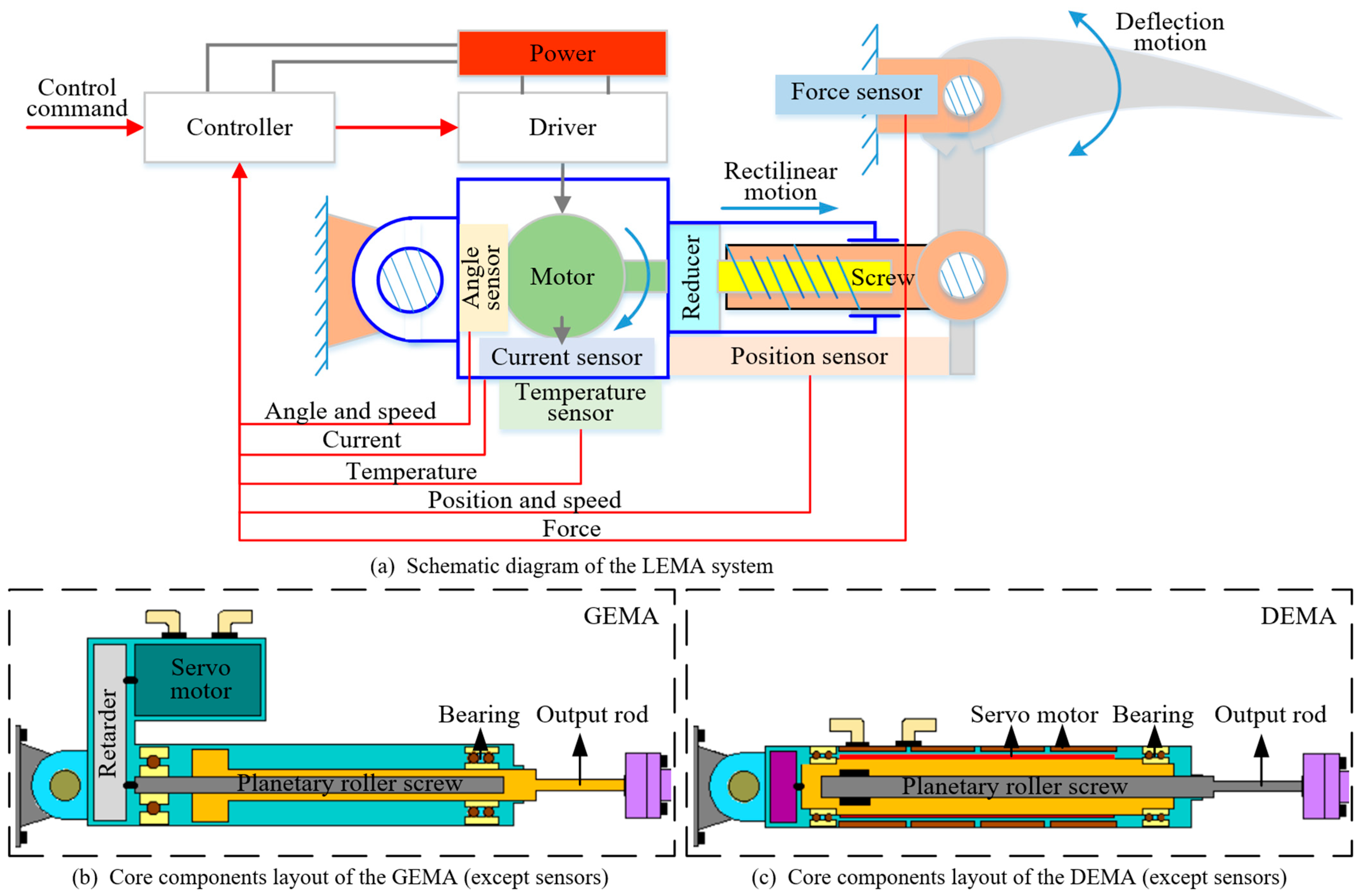
Figure 1. Schematic and structural diagram of the LEMA system.
Actuators 13 00377 g001
Figure 2. Open-loop system model block diagram of the PMSM.
Actuators 13 00377 g002
Figure 3. Open-loop system model block diagram of the planetary-roller screw pair.
Actuators 13 00377 g003
Figure 4. Open-loop system model block diagram of the force sensor.
Actuators 13 00377 g004
Figure 5. Open-loop system model block diagram at the load connection point.
Actuators 13 00377 g005
Figure 6. Open-loop model block diagram of the force servo system.
Actuators 13 00377 g006
Figure 7. Step response curve after the introduction of speed feedback.
Actuators 13 00377 g007
Figure 8. System model block diagram after the introduction of a PID controller.
Actuators 13 00377 g008
Figure 9. Step response curve of the force servo system.
Actuators 13 00377 g009
Figure 10. Sinusoidal response curve of the force servo system (1 Hz).
Actuators 13 00377 g010
Figure 11. Sinusoidal response curve of the force servo system (5 Hz).
Actuators 13 00377 g011
Figure 12. Sinusoidal response curve of the force servo system (10 Hz).
Actuators 13 00377 g012
Figure 13. System model block diagram with the feedforward correction element added.
Actuators 13 00377 g013
Figure 14. Simulation model of the force servo system.
Actuators 13 00377 g014
Figure 15. Response curve of the force servo system.
Actuators 13 00377 g015
Figure 16. Step response curve of the force servo system.
Actuators 13 00377 g016
Figure 17. Sinusoidal response curve of the force servo system (5 Hz).
Actuators 13 00377 g017
Figure 18. Sinusoidal response curve of the force servo system (10 Hz).
Actuators 13 00377 g018
Figure 19. Open-loop model block diagram of the position servo system.
Actuators 13 00377 g019
Figure 20. Simulation model of the position servo system.
Actuators 13 00377 g020
Figure 21. Response curve of the position servo system.
Actuators 13 00377 g021
Figure 22. Dual-channel EMA performance testing system.
Actuators 13 00377 g022
Figure 23. Static anti-disturbance performance. (a) Static anti-disturbance performance of the DEMA. (b) Static anti-disturbance performance of the GEMA.
Actuators 13 00377 g023
Figure 24. Dynamic anti-disturbance performance. (a) Dynamic anti-disturbance performance of the DEMA. (b) Dynamic anti-disturbance performance of the GEMA.
Actuators 13 00377 g024
Disclaimer/Publisher’s Note: The statements, opinions and data contained in all publications are solely those of the individual author(s) and contributor(s) and not of MDPI and/or the editor(s). MDPI and/or the editor(s) disclaim responsibility for any injury to people or property resulting from any ideas, methods, instructions or products referred to in the content.