Article

Experimental Analysis of Electrohydrodynamic Jet Actuation Modes Based on the Phase Doppler Technique

C-MAST (Centre for Mechanical and Aerospace Science and Technologies), Universidade da Beira Interior, 6201-001 Covilhã, Portugal
*
Author to whom correspondence should be addressed.
Actuators 2025, 14(3), 141; https://doi.org/10.3390/act14030141
Submission received: 6 February 2025 / Revised: 5 March 2025 / Accepted: 10 March 2025 / Published: 13 March 2025

Abstract

:
Electrosprays have garnered significant interest across various fields, from automotive painting to aerospace propulsion, due to their versatility and precision. This study aims to explore the formation and behavior of the Taylor cone in electrospray systems through the observation of the different characteristics of the produced droplets, in a way to enhance the control of the electrohydrodynamic jet. To obtain these results, the SpraySpy equipment was used, based on the phase Doppler technique, obtaining several characteristics of the droplets, such as velocity, size and distribution for a single liquid, acetone. These characteristics were acquired by varying parameters, namely the distance between the emitter and the collector, the liquid flow rate and the diameter of the emitter. Additionally, a high-speed camera was used to capture the cone angle, in the same operating conditions. The findings revealed a considerable decrease in particle velocity with an increase in the flow rate, while droplet size exhibited a noticeable tendency to grow under the increase in the emitter diameter. These insights aim to provide a deeper understanding of the relationship between these operational parameters and droplet behavior, contributing to the improvement of electrospray applications.

1. Introduction

Electro spraying consists of a technique where droplets are generated from a conductive liquid passing through a needle with the influence of high voltage. Firstly, the liquid is fed through the emitter at a steady and very low rate. A strong electric field is created at the tip of the emitter by applying a very high voltage between the emitter and the grounded collector. This causes electrostatic forces to be exerted on the liquid surface, pulling it outward, while the surface tension of the liquid opposes this, keeping it in a spherical shape when in equilibrium. When the electric field reaches a critical value, the electrostatic forces compel the liquid into a conical shape, known as the Taylor cone, given its name due to the research conducted by Sir Geoffrey Taylor [1]. From the cone’s apex a thin jet of liquid is emitted, which quickly becomes unstable, breaking up into tiny, charged droplets, with a more optimal control and distribution. The formed jets can be separated into different functioning modes, with the main ones being dripping, micro dripping, simple jet, cone-jet, multi-jet, ramified jet and spindle mode [2]. This study focuses on the Taylor cone formation and the cone-jet mode, which is the most stable mode, despite having a very narrow range of necessary applied voltage [3].
This topic was introduced by Zeleny in the early 20th century while conducting an experiment on the instability of electrified liquid surfaces [4,5]. It was only researched again almost half a century later by Sir Geoffrey Taylor, who further explained the phenomenon [1,6]. The research was continued by Hayati et al. [7], Cloupeau and Prunet-Foch [2,8], De La Mora et al. [9,10,11], Chen and Pui [12] and Gañán-Calvo et al. [13,14,15,16], among others, who studied the effects of the electric field, charge and current, the fluid dynamics, scaling laws, different functioning spraying modes of electro spraying and more specific themes. More recently, modeling has become a focal point of electrohydrodynamic jets, predicting jet performance and particle size and studying Taylor cone instabilities [17,18,19].
The research of electrohydrodynamic jets and Taylor cone parameters was backed by the need for more detailed control over the produced jet, which is crucial in the development and improvement of diverse applications, such as the atomization for spectrometry [20,21], size distribution optimization [22,23] and aerospace propulsion [24,25]. Nevertheless, one of the most important applications is the deposition of particles, which is used by micro/nanofabrication processes [26,27], inkjet printing [28,29], painting, coating and material processing [30,31,32,33] and drug delivery [34,35,36].
According to the literature, the formation and control of the cone-jet electro spraying process strongly depends on the liquid properties and operating parameters, including the applied potential, liquid flow rate, emitter diameter, viscosity, conductivity and surface tension. Therefore, it is important to further study the parameters and thus optimize the use of this technology in the industry. Notably, previous studies have explored specific aspects of electrospray systems, examining effects of emitter distance and diameter on reaction rates [37], correlating these factors with droplet size and discussing how varying the emitter-to-collector distance impacts droplet travel time and subsequent reactions [38]. While these studies provide valuable insights for isolated parameters, this study focuses on the combined effects of emitter-to-collector distance, emitter diameter, and flow rate on droplet size and velocity. To address this gap, the current work employs the phase Doppler technique of the SpraySpy system to analyze particles generated by electrosprays. This technique has previously been used, in the 1990s, by Tang and Gomez, to study the charge and fission of droplets [39] and the structure of monodisperse droplets [40] and by Olumee et al. to study the dynamic changes in droplets [41]. More recently, it was also used by Rosell-Llompart et al. [42] and Sultan et al. [43] to study the velocity and size of droplets on the formation of the Taylor cone and the subsequent spray development and how different electrospray modes and the presence of coflowing air impacted the produced droplets.
The behavior of electrosprays is strongly influenced by the working fluid and its physical properties, with the key ones being electrical conductivity, viscosity, surface tension and the permittivity of the liquids. These properties influence important aspects such as the stability of the Taylor cone, jet breakup and droplet formation. For this study, the formed droplet characteristics are of particular interest, given the implementation of the phase Doppler system. According to the literature, liquids with high viscosity tend to produce larger droplets, and thus are slower, due to the resistance to flow and jet breakup [44,45]. In high viscosity liquids, droplet characteristics are also relatively insensitive to the applied voltage [46]. A higher electrical conductivity generally leads to smaller droplets, due to an enhancement on the charge transport, which affects the jet breakup [44,47]. For low to moderate conductivity, the droplet size increases with a decrease in the electric Reynolds number [48]. While higher surface tension can lead to larger and slower droplets, by resisting the jet breakup, a higher permittivity can lead to smaller and faster droplets by enhancing the electric field’s effect [44,45]. This study focuses on acetone as a model fluid due to its moderate and well-characterized physical properties.
The purpose of this work is to conduct a parametric study of the cone-jet mode, utilizing a single liquid, acetone. The different parameters, such as the emitter–collector distance, the liquid flow rate and the emitter diameter will be varied in order to determine their impact on the size, distribution and velocity of the produced droplets. To better analyze the effect of each parameter, a high-speed camera was also utilized to capture the cone angle. To achieve such means, the experimental equipment and techniques used will be explained, followed by a detailed analysis and discussion of the results obtained, which will be summarized in the conclusion of the study.

2. Materials and Methods

In general, an electrospray experimental setup is relatively straightforward and requires a conductive emitter and a collector, a supply system for the liquid and a high-voltage power supply. For more detailed experiments, other equipment such as high-speed cameras, phase Doppler devices and Faraday cages may be used.
For this experiment, the chosen liquid was based on preliminary experiments involving three liquids, acetone, ethylene glycol and ethanol, where acetone achieved better results with the phase Doppler. Acetone’s physical properties also came under consideration given its moderate surface tension of 23.7 mN/m, dielectric constant of 21.4, electrical conductivity of 2 × 10⁷ pS/m and low viscosity of 0.32 mPa·s [49] at 20 °C which allow for a more stable particle formation.
A fixed time interval was chosen for the PDPA measurements to ensure uniformity in experimental observation duration across varying electrospray conditions. Each trial consisted of a 30 s run-time experiment, with the intention of having a more standardized comparison of the effects of the chosen parameters, keeping in mind the dynamic nature of electrosprays and possible temporal effects.

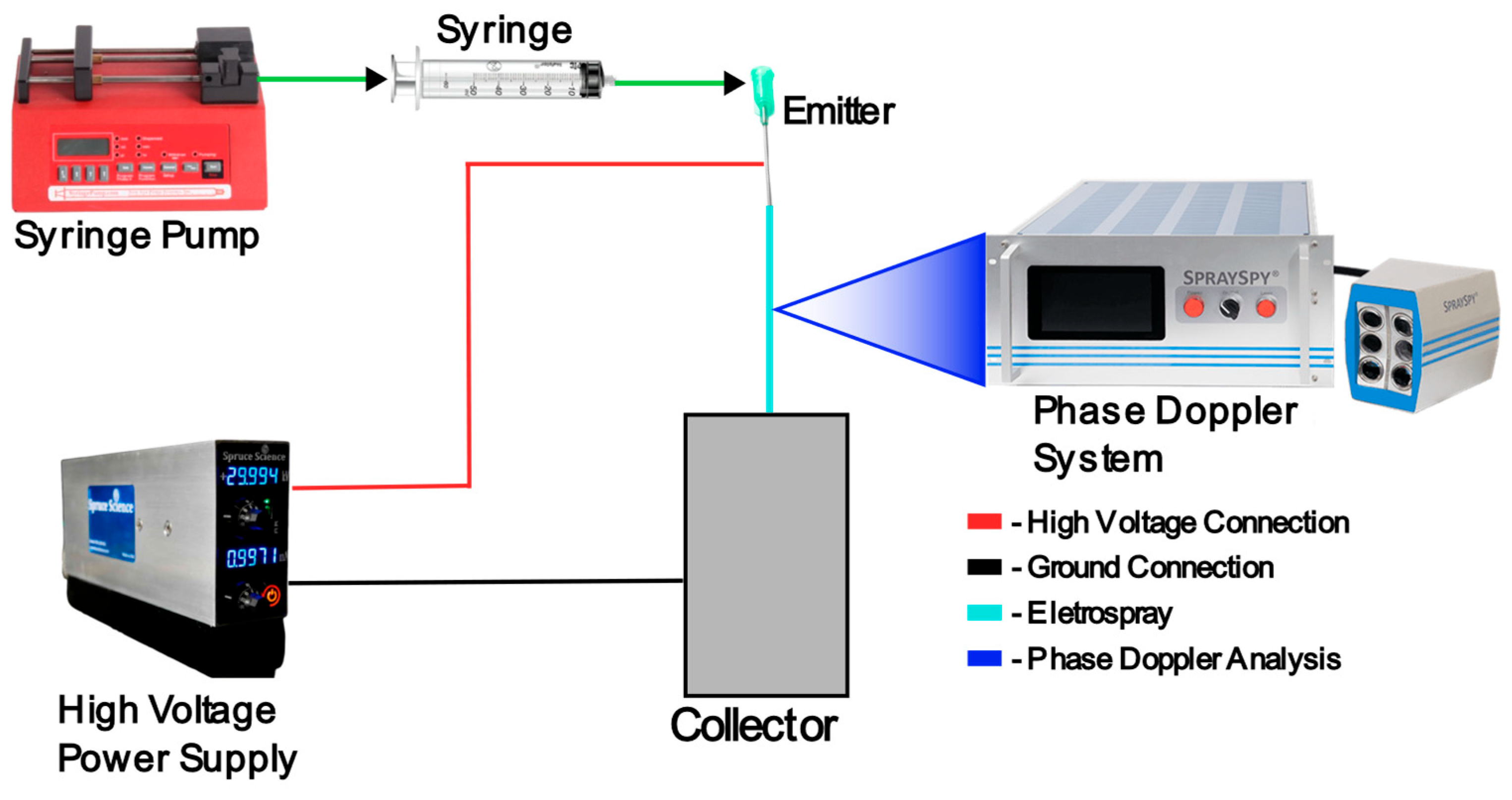
2.1. Electrospray Setup

For this experiment, a “Spruce Science” Taylor cone support was used to hold the emitter, which consists of an electrically conductive needle with various diameters, and the collector. This support is uncomplicated, consisting of an acrylic structure with an adjustable z axis for the variation in the emitter to diameter distance. The liquid supply system consisted of a syringe pump, with a syringe placed on it, acting as a reservoir for the liquid. In turn, this syringe was connected to the emitter with the help of silicon tubing, feeding the liquid at a controlled flow rate to the emitter. The high-voltage power supply was also placed separately, connecting the positive terminal to the emitter and grounding the collector. The power supply allows the creation of the electric field which is needed for the electrospray to function. The “SpraySpy” device was placed at a distance of 12 cm from the created electrohydrodynamic jet, and a 1 cm vertical distance from the Taylor cone in order to analyze the produced droplets. This entire experimental procedure is depicted in Figure 1.

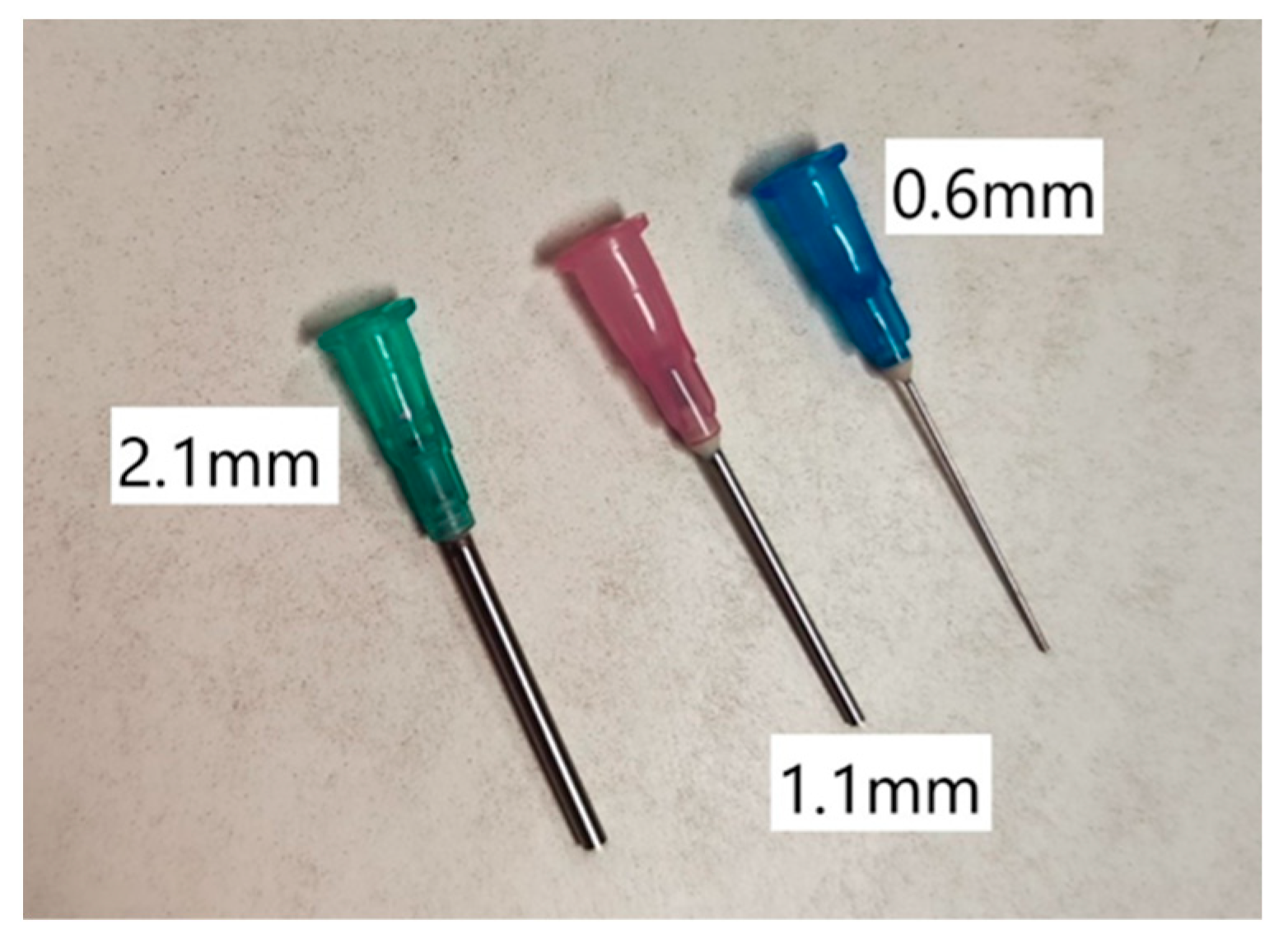
2.2. Emitter and Collector

The emitter and collector have a significant impact on the produced droplets. Not only the distance between them but also the diameter of the emitter can significantly affect the process. While the collector chosen was a metal plate with a flat surface, the emitter required a more thoughtful selection. While there are many different types of emitters, the three main categories are the externally wetted, porous and internal capillary [50]. The latter one is the most common and the one chosen for this study, due to its ease of use and simplicity.
For this study, three different diameters were considered, with emitters of 0.6 mm, 1.1 mm and 2.1 mm external diameters being chosen, as shown in Figure 2. The wall thickness of the capillaries was 0.1 mm, with their internal diameter being 0.5 mm, 1.0 mm and 2.0 mm, respectively. To further examine the effect of the distance between the emitter and the collector on the produced droplets, three set distances of 10, 20 and 30 mm were used.

2.3. Supply Systems

This experimental setup has two different supply systems, the liquid supply system and the power supply system.
The liquid supply system consists of a syringe pump, model NE-300 from New Era Pump Systems Inc. (Farmingdale, NY, USA), capable of holding one syringe up to 60 mL, with flow rates of 0.73 µL/h to 1500 mL/h [51]. The device had a syringe inserted into it, with the desired liquid, which was connected directly to the emitter, being held at the Taylor cone support, with the help of a short silicon tube.
This equipment is crucial to control the liquid flow rate of the electrospray which is one of the parameters that most influence the electrohydrodynamic jet. For this study, this device was set to flow rates of 0.5, 2.5, 5, 7.5 and 10 mL/h.
On the other hand, the power supply system is a Lab Mate High Voltage Power Supply from Spruce Science (Sunnyvale, CA, USA), which can deliver voltages up to 30 kV with a maximum current of 1 mA, with ultra-low ripple (0.0001%), great stability and high accuracy [52]. It was used to create the electric field necessary for electro spraying, with its positive terminal connected to the metallic section of the needle, and its negative terminal connected to the collector.
The applied electrical potential for each trial was based on the visual stability of the Taylor cone for each experiment conducted with the values being presented in Table 1.

2.4. Phase Doppler System

The main equipment that allowed the flow behavior analysis in the current study is the SpraySpy LabLine from AOM Systems (Heppenheim, Germany). This equipment measures spatially resolved single droplet events, with simultaneous measurement of the size, distribution and velocity of drops, all based on the phase Doppler technique. In this technique, two lasers are placed in a way that they intersect each other, forming a set of parallel equidistant fringes. As the droplet intercepts them, it scatters the light which is then received by multiple receptors. These receptors convert the optical signal into a Doppler burst. The droplet’s size is acquired by the phase shift between two detector’s signals and the velocity is obtained through the signal’s frequency [53]. This equipment possesses two lasers which meet at a distance of 12 cm from the lenses, and four photo-sensitive cells which gather the information from the lasers. The equipment was centered and placed at a vertical height of 1 cm below the Taylor cone in each experiment, despite the emitter–collector distance variations. This equipment allows for obtaining a detailed and easy analysis of the electrospray and its characteristics, with an uncertainty of ±0.1 µm for the size and ±0.1 m/s for the droplet velocity and minimum values of 1 µm and 1 m/s, respectively [54].

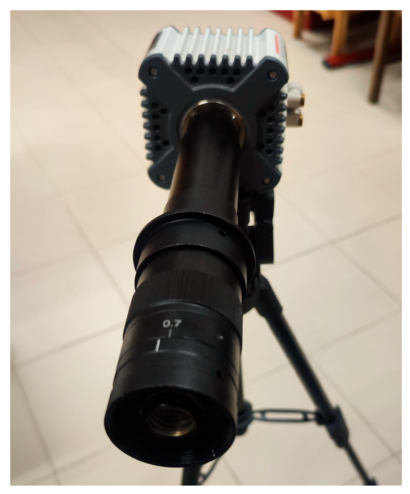
2.5. High-Speed Camera

The visualization and analysis of the Taylor cone angle are essential for understanding the electrohydrodynamic jet formation process. This visual characteristic provides insights into the stability of the electrospray and the effects of the operating parameters on jet behavior. As such, the ORCA-R2 camera (Hamamatsu Photonics, Shizuoka, Japan) allowed for the capturing of the high-speed images that resulted in the study of the Taylor cone angle under varying operating conditions. This camera was chosen due to its high sensitivity, low noise and fast acquisition capabilities. It possesses a quantum efficiency of around 70% at 600 nm, with a capacity of up to 16.2 frames per second, at full resolution, and a dual cooling system to maintain high performance [55]. The camera was placed at a distance of 33 cm from the emitter, and with a lens of 0.7, as shown in Figure 3.

3. Results

This study used a reference value of 7.5 mL/h for the flow rate, 1.1 mm for the emitter outer diameter and 20 mm for the distance from the emitter to the collector. For each different parameter variation, only that specific parameter was altered, while the other two parameters remained as the reference values. Each experiment consisted of a 30 s run-time analysis, utilizing the phase Doppler at a fixed position on the spray, showcasing an absolute value of droplet quantity.

3.1. Flow Rate

The study of the flow rate parameter was achieved by utilizing five defined flow rates, 0.5, 2.5 (red), 5 (magenta), 7.5 (blue) and 10 mL/h (green). The emitter diameter and emitter–collector distance were constant at 1.1 mm and 20 mm, respectively. There was no formation of a steady cone-jet at 0.5 mL/h, leading directly from micro-dripping to multi-jet mode. Also at 2.5 mL/h, since the flow rate was still low, the droplet count was inferior when compared to the other values, as shown in Figure 4 and Figure 5, in red.
In Figure 4, it is possible to see that the diameter of the produced drops tends to stay rather constant throughout the increase in the flow rate, with no major drop or rise in the values, only a slight decrease, with an exception at 2.5 mL/h, due to the low quantity of droplets obtained. This trend can be attributed to the competing influences of the electric field and the liquid inertia. At lower flow rates, the electric field dominates the breakup process, generating small droplets; however, this effect is counteracted by the inertia as the flow rate increases. Despite this, we can see a bigger concentration of droplets between 0 and 5 µm, and a solid distribution from 5 to 25 µm, and very few to no droplets past that, on all flow rates.
Examining Figure 5, it is evident that there is a decrease in the overall velocity of the droplets with the increase in the flow rate. We can see that at 2.5 mL/h, in red, there is a bigger collection of droplets around 9–12 m/s, meanwhile at 5 mL/h, in pink, we can see a decrease to 8–10 m/s, and at 7.5 mL/h another reduction to 6–9 m/s, shown in the blue graphic. At the last flow rate, represented by green, while the bigger concentration of droplets stays similar to the previous flow rate, we can see a slightly higher distribution at the lower velocities, indicating a decrease in the average velocity. Higher flow rates correspond to initial droplet sizes, which can experience drag forces, reducing acceleration. The charge-to-mass ratio also decreases at higher flow rates, resulting in weaker electrostatic attraction and thus creating a tendency for the velocity to decrease.
This study experienced a challenge when trying to stabilize the cone-jet mode at ultra-low flow rates, particularly at 0.5 mL/h, where the transition from micro-dripping to multi-jet mode was observed instead of a steady cone-jet. This limitation suggests that specific operational constraints arise at this flow rate, which could be attributed to both material specific properties and system configuration. One of the main factors for this instability could be configuration variables such as voltage gradients and emitter configuration that can deeply affect the cone-jet mode stability. These parameters can impact the electric field, challenging the stable jet formation, even with very slight variations. Additionally, this challenge could be attributed to the low viscosity and high volatility of acetone, which leads to evaporation, affecting the jet and droplet formation.
Previous studies have highlighted how liquid properties have an important influence on jet stability, dictating the threshold of minimum flow rate required for a stable electrospray [22]. When electrosprays are near this threshold, they tend to exhibit pulsations and instabilities that further disrupt droplet uniformity, especially for liquids such as acetone, which are low-viscosity and high volatility [56]. Recent studies have also shown that at ultra-low flow rates, at the nano-liter scale, even slight variations in the conductivity and surface tension of liquids can significantly alter the cone-jet mode [57]. Meanwhile, the literature has also proven that higher viscosity liquids are less sensitive to jet breakup when compared to lower viscosity solvents [58]. Furthermore, on the numerical side, simulations exhibited that the tuning of applied voltage and even emitter geometry allowed for the control of electrospray mode transitions at low flow rates [59].

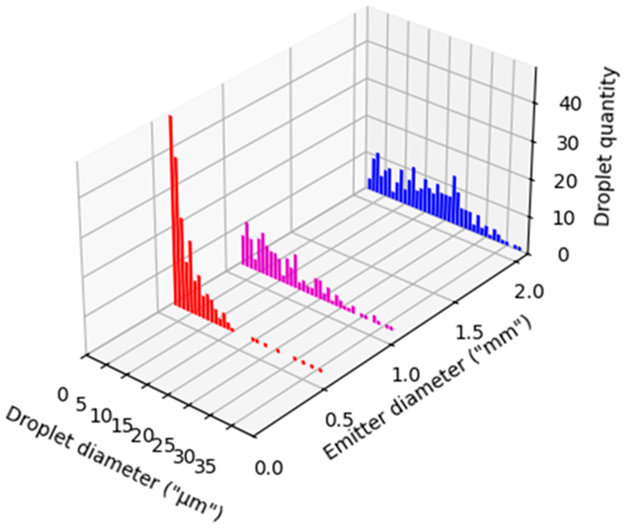
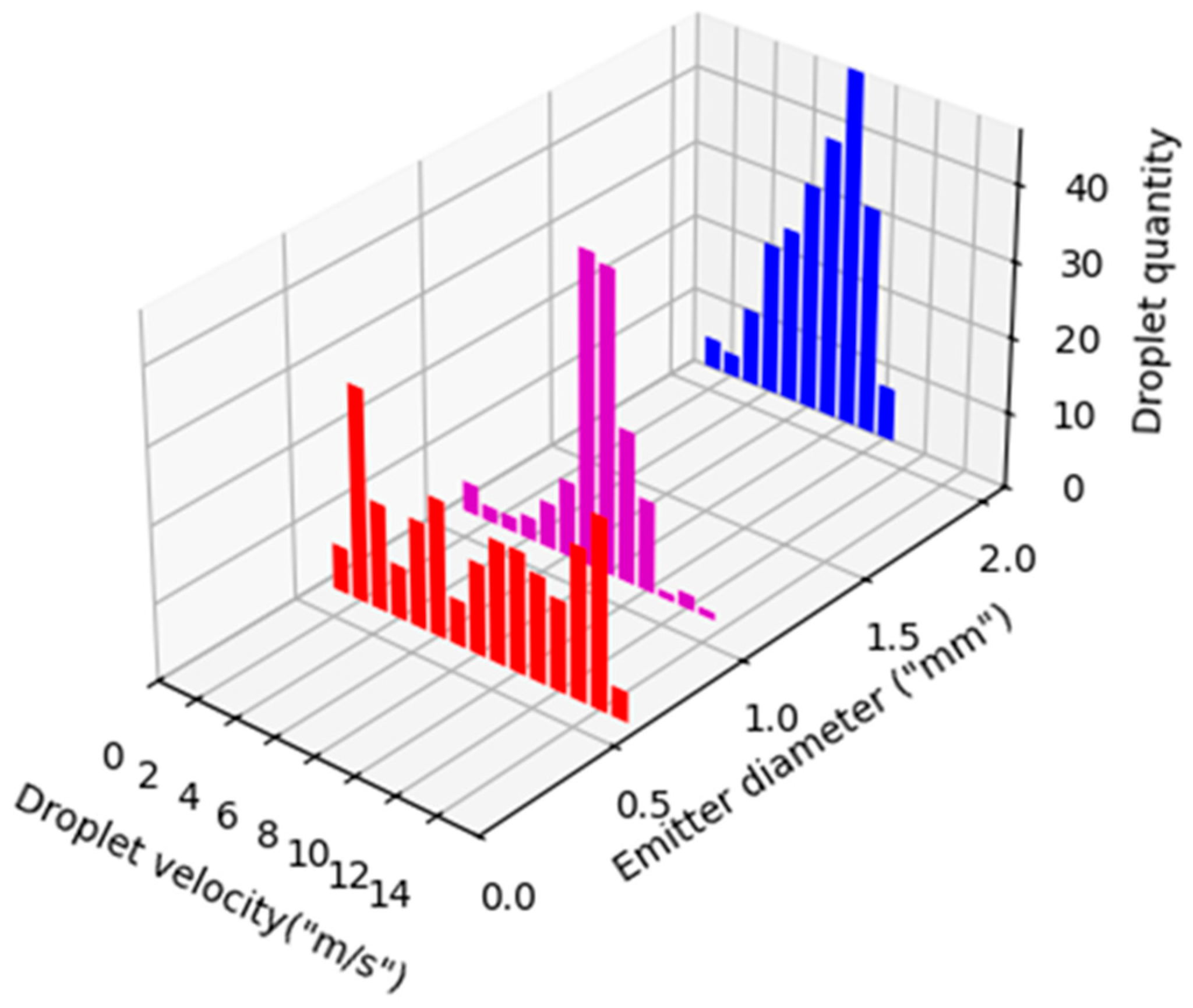
3.2. Emitter Diameter

In order to study the effect of the emitter diameter in the electrospray results, three diameters of 0.6 (red), 1.1 (magenta) and 2.1 mm (blue) were used. The flow rate and emitter to collector distance were constant, with values of 7.5 mL/h and 20 mm, respectively. Referring to Figure 6 and Figure 7, we can see that in the red graphic, which represents 0.6 mm, we have a smaller droplet size, with a higher and more distributed velocity.
In Figure 6, at 1.1 mm, in pink, we have a slightly higher droplet diameter than 0.6 but the tendency is to increase as we can see at 2.1 mm, depicted in blue, having a more distributed and higher average droplet diameter. This increase happens due to the greater volume of liquid and lower charge density present in higher diameters, which leads to a reduced electrostatic repulsion, allowing for the formation of larger droplets.
As far as the velocity is concerned, the tendency is the opposite, with a decrease in velocity from 0.6 mm to 1.1 mm and from the latter to 2.1 mm of diameter. In Figure 7, while the 0.6 mm velocities are distributed, it is possible to examine a higher concentration of droplets at 1.1 mm and 2.1 mm, of 4–8 m/s and 2–7 m/s, respectively. The larger droplets produced by bigger diameters contain more mass which leads to lower acceleration. This decrease is also influenced by charge distribution, given that the broader area of a larger emitter results in weaker electrostatic forces acting on the droplets.

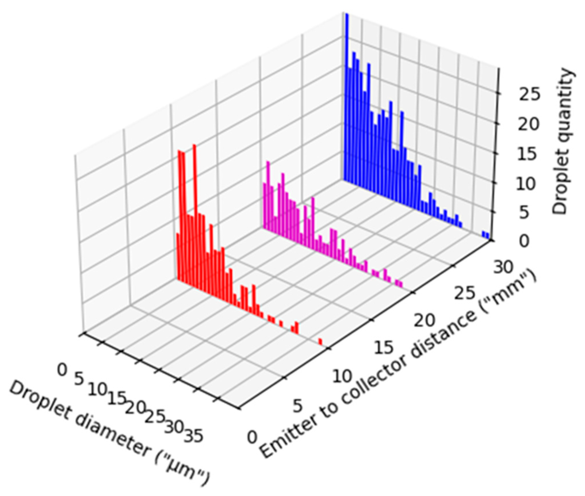
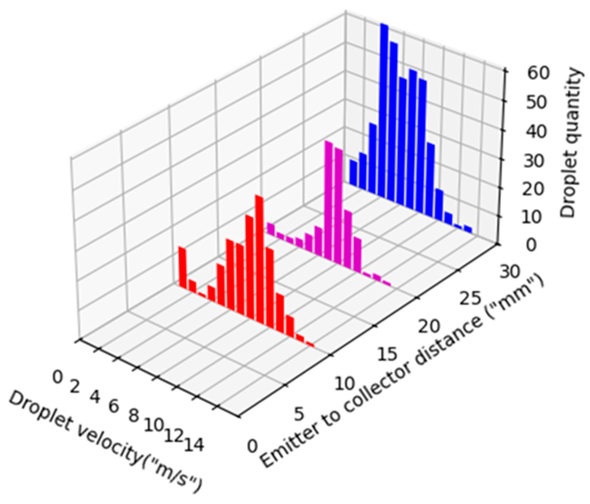
3.3. Emitter to Collector Distance

For this study, three distances from the tip of the emitter to the collector plate were used to observe the impact of this parameter. The distances were 10 (red), 20 (magenta) and 30 mm (blue), with a fixed flow rate of 7.5 mL/h and emitter outer diameter of 1.1 mm.
As it is possible to see in Figure 8, as the distance gets larger, the particle’s diameter stays constant with a slight increase in the average diameter. This is observed by the bigger dispersion of the quantity of droplets at 30 mm distance, having a bigger distribution above 15 µm when compared to the other two graphics. The slight increase in droplet size can be attributed to the evaporation of smaller droplets and coalescence.
In terms of velocity, there is a more noticeable variation in Figure 9, with a decrease as the distance gets longer. It is possible to notice this through a bigger distribution of droplets at a 30 mm distance, around 4–8 m/s, compared to the distribution of 7–9 m/s and 6–10 m/s, at the 20 mm and 10 mm distances, respectively. The longer travel path at higher distances allow for more time of drag forces being exerted on the droplets, reducing their terminal velocity, resulting in a decrease. Additionally, as the electric field lessens with the distance, the acceleration of the particles also weakens.

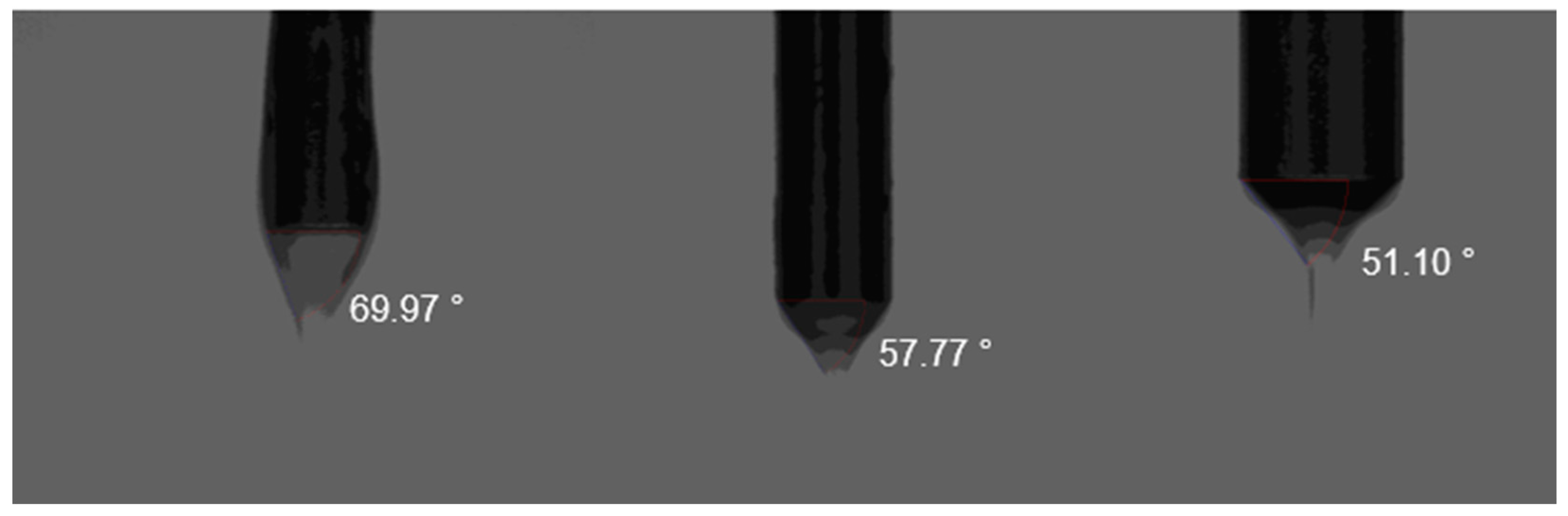
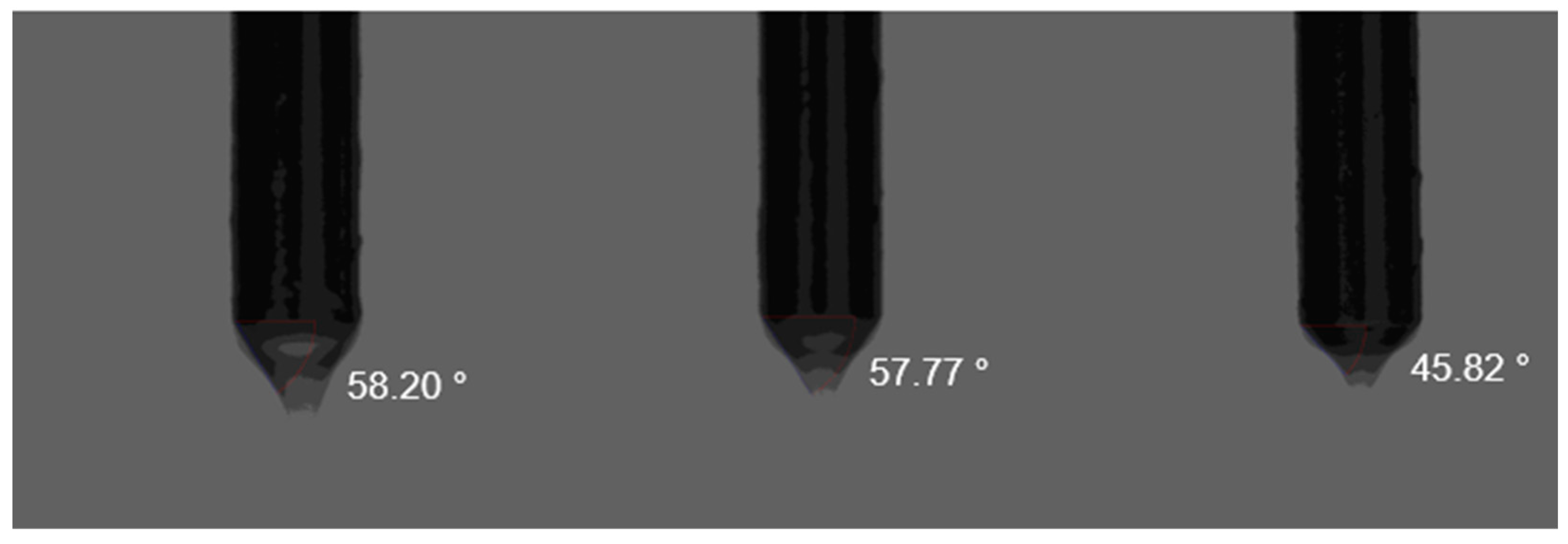
3.4. Taylor Cone Angle

The cone angle is a critical parameter in electrospray processes, as it directly affects the jet stability and droplet dispersion. Thus, it is crucial to also analyze the cone angle tendencies with the parameters variation. By capturing high-speed images of the electrospray process, the cone angle was measured using an image editing software Inkscape, v1.4.
In Figure 10, the cone angle exhibits a strong dependence on flow rate, with smaller angles observed at lower flow rates, and a constant increase in angle with the flow rate increase that becomes significantly smaller from 7.5 to 10 mL/h. This increase is due to the higher liquid supply rate which results in a more pronounced liquid meniscus before nebulization. The cone shape remains rather constant, with no major visual variation in its shape or size.
The cone angle variation is most prominent with the emitter diameter increase. We have a prominent reduction on the cone angle values from 0.6 to 1.1 mm, with a smaller variation from 1.1 to 2.1 mm, as shown in Figure 11. The visual analysis of each Taylor cone showcases a significant variation in its geometry, with the 0.6 mm diameter having a longer but wider cone when compared to 2.1 mm which has a smaller angle and thus a more thin cone. This phenomenon can be explained by the charge distribution, which results in a reduced electrostatic force, over a broader area, leading to a more narrow cone.
The cone angle follows the same tendency with the emitter to collector distance as the emitter diameter. We can notice a decrease in the angle but it is most prominent from 20 to 30 mm, with the variation from 10 to 20 mm being almost null, as evidenced in Figure 12. The jet behavior is rather similar in the first two distances, with the 30 mm distance showcasing a much narrower Taylor cone. This is likely due to the weakened electric field at 30 mm, which alters the shape of the Taylor cone.

3.5. Experimental Parameter Study

To better summarize the experimental parameter study conducted, Table 2 presents the three parameters studied and the median values of droplet size and velocity given by the SpraySpy software version 2229. The use of median values are due to the presence of outliers and the inherently skewed distribution of droplet characteristics in electrospray processes. Moreover, median values provide a more robust and representative measure of typical droplet behavior, minimizing the influence of extreme variations.
Analyzing the median values, it is noticeable that the emitter diameter presented the biggest influence on the particle size, with a total increase of 13 µm on the median droplet size, from the 0.6 mm to 2.1 mm diameter. Meanwhile, the emitter to collector distance had a minor impact when compared to the previous parameter, with only a total variation of 3 µm. The flow rate had little influence on the size, which stayed constant until 10 mL/h where there was only a 1 µm decrease.
In terms of velocity, it is possible to observe a decrease in every median value obtained, with the flow rate having a bigger influence on the velocity, with a total variation of 3.5 m/s but a tendency to decrease the discrepancy of the values. The emitter diameter had a similar behavior but a smaller total variation of only 1.5 m/s. In regard to the emitter to collector distance, the total variation in velocity was of 2.4 m/s but the behavior was opposite to the other parameters, with a tendency to grow the discrepancy.

3.6. Results Comparison

The findings of this study reveal distinct trends in droplet size and velocity as a function of the different parameters studied. The universality of these trends across different liquids remains an open question due to the various physical properties of different liquids. As it was referred previously, the electrospray technique is highly sensitive to the fluid properties. However, prior research has demonstrated that some trends remain consistent across a wide range of fluids. Examples of this are the flow rate, which produces larger droplet sizes with its increase [48,60], and the emitter diameter, which also produces larger, and thus slower, droplets with its increase [37,61], which is also verified in our experiment. Despite this, as the distance between the emitter and collector increases, the general trend is for the droplets to become smaller due to the increased evaporation during flight [37], which is not verified in this experiment, where droplet size increased. This significant difference can be due to several experimental factors. Olumee et al. [41] attributed a similar occurrence to droplet coalescence, but other factors such as charge dissipation, increased residence time or even the specific acetone properties could contribute to this inconsistency.
As far as the cone angle goes, our study matches the results of Subbotin and Semenov [62], with an increase in the cone angle as the flow rate increases. In regard to the emitter to collector distance, Ryan et al. [63] validates the results, with a narrowing cone as the distance increases. Despite this, according to the same study, the emitter diameter should result in a bigger Taylor cone angle as it increases, which is the opposite of what was visualized in this experiment. Several factors could have led to such a difference, such as the electric field distribution, lower hydraulic resistance [63] and emitter wettability, which could result in a narrower cone angle [64].

4. Conclusions

In this work, it was possible to successfully create an electrohydrodynamic jet and examine the influence of three variable parameters: the flow rate, the emitter diameter and the emitter to collector distance. The phase Doppler technique utilized by using the SpraySpy equipment allowed for adequately capturing the distribution, velocity and size of the atomized droplets. With the information acquired, it was observed that the droplet velocity decreases with the increase in any of the parameters. Meanwhile, the droplet size exhibited distinct trends, remaining nearly constant with the increase in the flow rate, and displaying an increase with the emitter diameter and emitter to collector distances. Among the different parameters, emitter diameter had the most significant influence on the droplets’ sizes across the tested range. Contrarily, the flow rate showed a minimal impact on the particles’ sizes but considerably affected velocity with a total decrease of 3.5 m/s from 2.5 mL/h to 10 mL/h.
The cone angle was captured utilizing a high-speed camera. As the flow rate increased, the Taylor cone angle also increased. Contrarily, the increase in the emitter diameter and emitter–collector caused a decrease in the cone angle.
When comparing the acquired data to the previous literature, most of the tendencies matched the previous results, except for two, the size of the particles with the increase in the emitter–collector distance and the cone angle with the increase in the emitter diameter. While these results did not achieve what was expected, these phenomena were also already explicit in the literature, accompanied by probable factors. In the future, such factors can be considered to achieve better and more comprehensive results.
These results provide valuable insights into electrospray behavior for acetone. However, the universality of these patterns requires additional investigation. Future work should explore a broader range of liquids, with distinct properties, to establish generalized patterns for electrospray applications and enhance the precision of these technologies.
Some challenges were encountered when trying to stabilize the cone-jet mode at lower flow rates. At 0.5 mL/h, it was not possible to observe a stable cone-jet formation, transitioning directly from micro-dripping to multi-jet mode. This occurred due to the liquid properties of acetone and specific electrospray conditions utilized in the experiment, further reinforcing the importance of further studies in this subject. Thus, there is a need to investigate different liquid properties and test-modified electrospray configurations in order to further optimize control. Also, the inclusion of lower flow rates could establish a more comprehensive electrospray operating map and enhance jet stability.
This research contributes to a more detailed understanding of electrospray behavior under different parameters, while also providing valuable insights for the diverse range of electrospray applications. This work also serves as a basis for future electrospray studies, which can be used as a comparison for works integrating high-voltage control rings or plasma actuators to actively manipulate the electrospray, utilizing the same operational parameters and analyzing the behavior of the particle characteristics.

Author Contributions

Conceptualization, G.N. and M.M.; methodology, G.N. and M.M.; formal analysis, G.N. and M.M.; investigation, G.N.; resources, F.R. and J.P.; writing—original draft preparation, G.N.; writing—review and editing, G.N., F.R. and J.P.; supervision, F.R. and J.P.; project administration, F.R. and J.P.; funding acquisition, F.R. and J.P. All authors have read and agreed to the published version of the manuscript.

Funding

This research was funded by Project GreenAuto: Green Innovation for the Automotive Industry, grant number 02/C05-i01.02/2022.PC644867037-00000013, from the Incentive System to Mobilizing Agendas for Business Innovation, funded by the Recovery and Resilience Plan, and by the Portuguese Foundation for Science and Technology through the research unit C-MAST (Center for Mechanical and Aerospace Science and Technology), Research Unit No. 151, project grant numbers UIDB/00151/2020 and UIDP/00151/2020 (https://doi.org/10.54499/UIDB/00151/2020; https://doi.org/10.54499/UIDP/00151/2020).

Data Availability Statement

Data are contained within the article.

Conflicts of Interest

The authors declare no conflicts of interest.

Abbreviations

The following abbreviations are used in this manuscript:
PDPAPhase Doppler Particle Analyzer

References

  1. Taylor, G. Disintegration of water drops in an electric field. Proc. R. Soc. Lond. A Math. Phys. Sci. 1964, 280, 383–397. [Google Scholar] [CrossRef]
  2. Cloupeau, M.; Prunet-Foch, B. Electrohydrodynamic spraying functioning modes: A critical review. J. Aerosol Sci. 1994, 25, 1021–1036. [Google Scholar] [CrossRef]
  3. Kim, J.Y.; Lee, S.J.; Hong, J.G. Spray Mode and Monodisperse Droplet Properties of an Electrospray. ACS Omega 2022, 7, 28667–28674. [Google Scholar] [CrossRef]
  4. Zeleny, J. Electrical discharges from pointed conductors. Phys. Rev. B 1920, 16, 102–125. [Google Scholar] [CrossRef]
  5. Zeleny, J. Instability of electrified liquid surfaces. Phys. Rev. B 1917, 10, 1. [Google Scholar] [CrossRef]
  6. Melcher, J.R.; Taylor, G.I. Electrohydrodynamics: A Review of the Role of Interfacial Shear Stresses. Annu. Rev. Fluid Mech. 1969, 1, 111–146. [Google Scholar] [CrossRef]
  7. Hayati, I.; Bailey, A.I.; Tadros, T.H.F. Investigations into the Mechanisms of Electrohydrodynamic Spraying of Liquids I. Effect of Electric Field and the Environment on Pendant Drops and Factors Affecting the Formation of Stable Jets and Atomization. J. Colloid Interface Sci. 1987, 117, 205–221. [Google Scholar] [CrossRef]
  8. Cloupeau, M.; Prunet-Foch, B. Electrostatic spraying of liquids in cone-jet mode. J. Electrost. 1989, 22, 135–159. [Google Scholar] [CrossRef]
  9. De La Mora, J.F. The fluid dynamics of Taylor Cones. Annu. Rev. Fluid Mech. 2007, 39, 217–243. [Google Scholar] [CrossRef]
  10. De La Mora, J.F. The effect of charge emission from electrified liquid cones. J. Fluid Mech. 1992, 243, 561–574. [Google Scholar] [CrossRef]
  11. De La Mora, J.F.; Loscertales, I.G. The current emitted by highly conducting Taylor cones. J. Fluid Mech. 1994, 260, 155–184. [Google Scholar] [CrossRef]
  12. Chen, D.R.; Pui, D.Y.H. Experimental investigation of scaling laws for electrospraying: Dielectric constant effect. Aerosol Sci. Technol. 1997, 27, 367–380. [Google Scholar] [CrossRef]
  13. Gañán-Calvo, A.M. On the general scaling theory for electrospraying. J. Fluid Mech. 2004, 507, 203–212. [Google Scholar] [CrossRef]
  14. Gañán-Calvo, A.M. The Nature and Scaling Laws of the Surface Charge in Electrohydrodynamic Spraying. In Proceedings of the American Physical Society, Division of Fluid Dynamics Meeting, Philadelphia, PA, USA, 22–24 November 1998; Available online: https://www.researchgate.net/publication/241405133 (accessed on 24 January 2025).
  15. Gañán-Calvo, A.M.; Lasheras, J.C.; Vila, J.D.; Barrero, A. The electrostatic spray emitted from an electrified conical meniscus. J. Aerosol Sci. 1994, 25, 1121–1142. [Google Scholar] [CrossRef]
  16. Gañán-Calvo, A.M.; López-Herrera, J.M.; Herrada, M.A.; Ramos, A.; Montanero, J.M. Review on the physics of electrospray: From electrokinetics to the operating conditions of single and coaxial Taylor cone-jets, and AC electrospray. J. Aerosol Sci. 2018, 125, 32–56. [Google Scholar] [CrossRef]
  17. Cândido, S.; Páscoa, J.C. Data-driven surrogate modelling of multistage Taylor cone–Jet dynamics. Phys. Fluids 2024, 36, 052102. [Google Scholar] [CrossRef]
  18. Wang, F.; Elbadawi, M.; Tsilova, S.L.; Gaisford, S.; Basit, A.W.; Parhizkar, M. Machine learning predicts electrospray particle size. Mater. Des. 2022, 219, 110735. [Google Scholar] [CrossRef]
  19. Cândido, S.; Páscoa, J.C. Dynamics of three-dimensional electrohydrodynamic instabilities on Taylor cone jets using a numerical approach. Phys. Fluids 2023, 35, 052110. [Google Scholar] [CrossRef]
  20. Chiu, Y.-H.; Austin, B.L.; Dressler, R.A.; Levandier, D.; Murray, P.T.; Lozano, P.; Martinez-Sanchez, M. Mass spectrometric analysis of colloid thruster ion emission from selected propellants. J. Propuls. Power 2005, 21, 416–423. [Google Scholar] [CrossRef]
  21. Fenn, J.B.; Mann, M.; Meng, C.K.; Wong, S.F.; Whitehouse, C.M. Electrospray Ionization for Mass Spectrometry of Large Biomolecules. Science 1989, 246, 64–71. [Google Scholar] [CrossRef]
  22. Gamero-Castanõ, M.; Magnani, M. The minimum flow rate of electrosprays in the cone-jet mode. J. Fluid Mech. 2019, 876, 553–572. [Google Scholar] [CrossRef]
  23. Thuppul, A.; Collins, A.L.; Wright, P.L.; Uchizono, N.M.; Wirz, R.E. Mass flux and current density distributions of electrospray plumes. J. Appl. Phys. 2021, 130, 103301. [Google Scholar] [CrossRef]
  24. Chiu, Y.H.; Dressler, R.A. Ionic liquids for space propulsion. In ACS Symposium Series; ACS Publications: Washington, DC, USA, 2007; pp. 138–160. [Google Scholar] [CrossRef]
  25. Lenguito, G.; Gomez, A. Pressure-driven operation of microfabricated multiplexed electrosprays of ionic liquid solutions for space propulsion applications. J. Microelectromechanical Syst. 2014, 23, 689–698. [Google Scholar] [CrossRef]
  26. Morais, A.Í.S.; Vieira, E.G.; Afewerki, S.; Sousa, R.B.; Honorio, L.M.C.; Cambrussi, A.N.C.O.; Santos, J.A.; Bezerra, R.D.S.; Furtini, J.A.O.; Silva-Filho, E.C.; et al. Fabrication of polymeric microparticles by electrospray: The impact of experimental parameters. J. Funct. Biomater. 2020, 11, 4. [Google Scholar] [CrossRef] [PubMed]
  27. Jaworek, A. Micro- and nanoparticle production by electrospraying. Powder Technol. 2007, 176, 18–35. [Google Scholar] [CrossRef]
  28. Guo, L.; Duan, Y.; Huang, Y.A.; Yin, Z. Experimental study of the influence of ink properties and process parameters on ejection volume in electrohydrodynamic jet printing. Micromachines 2018, 9, 522. [Google Scholar] [CrossRef]
  29. Yu, M.; Ahn, K.H.; Lee, S.J. Design optimization of ink in electrohydrodynamic jet printing: Effect of viscoelasticity on the formation of Taylor cone jet. Mater. Des. 2016, 89, 109–115. [Google Scholar] [CrossRef]
  30. Grace, J.M.; Marijnissen, J.C.M. A review of liquid atomization by electrical means. J. Aerosol Sci. 1994, 25, 1005–1019. [Google Scholar] [CrossRef]
  31. Miao, P.; Balachandran, W.; Member, S.; Xiao, P.; Miao, P.; Balachandran, W. Formation of Ceramic Thin Films Using Electrospray in Cone-Jet Mode. IEEE Trans. Ind. Appl. 2002, 38, 50–56. [Google Scholar] [CrossRef]
  32. Pendar, M.R.; Rodrigues, F.; Páscoa, J.C.; Lima, R. Review of coating and curing processes: Evaluation in automotive industry. Phys. Fluids 2022, 34, 101301. [Google Scholar] [CrossRef]
  33. Maktabi, S.; Chiarot, P.R. Electrohydrodynamic printing of organic polymeric resistors on flat and uneven surfaces. J. Appl. Phys. 2016, 120, 084903. [Google Scholar] [CrossRef]
  34. Richardson, S.M.; Hoyland, J.A.; Mobasheri, R.; Csaki, C.; Shakibaei, M.; Mobasheri, A. Mesenchymal stem cells in regenerative medicine: Opportunities and challenges for articular cartilage and intervertebral disc tissue engineering. J. Cell. Physiol. 2009, 222, 23–32. [Google Scholar] [CrossRef] [PubMed]
  35. Guastaferro, M.; Baldino, L.; Cardea, S.; Reverchon, E. Supercritical-CO2-Assisted Electrospray for the Production of the PLA-Antibiotic-Sustained Drug-Delivery System. Processes 2023, 11, 2957. [Google Scholar] [CrossRef]
  36. Vu, H.-D.; Vu, T.-H.; Mai, N.L.; Pande, D.C.; Dao, D.V.; Rehm, B.H.; Nguyen, N.-T.; Grant, G.D.; Tran, C.-D.; Zhu, Y.; et al. In-flight electro-neutralisation electrospray for pulmonary drug delivery. Nano Today 2024, 55, 102217. [Google Scholar] [CrossRef]
  37. Marsh, B.M.; Iyer, K.; Cooks, R.G. Reaction Acceleration in Electrospray Droplets: Size, Distance, and Surfactant Effects. J. Am. Soc. Mass Spectrom. 2019, 30, 2022–2030. [Google Scholar] [CrossRef]
  38. Rovelli, G.; Jacobs, M.I.; Willis, M.D.; Rapf, R.J.; Prophet, A.M.; Wilson, K.R. A critical analysis of electrospray techniques for the determination of accelerated rates and mechanisms of chemical reactions in droplets. Chem. Sci. 2020, 11, 13026–13043. [Google Scholar] [CrossRef]
  39. Gomez, A.; Tang, K. Charge and fission of droplets in electrostatic sprays. Phys. Fluids 1994, 6, 404–414. [Google Scholar] [CrossRef]
  40. Tang, K.; Gomez, A. On the structure of an electrostatic spray of monodisperse droplets. Phys. Fluids 1994, 6, 2317–2332. [Google Scholar] [CrossRef]
  41. Olumee, Z.; Callahan, J.H.; Vertes, A. Droplet dynamics changes in electrostatic sprays of methanol—Water mixtures. J. Phys. Chem. A 1998, 102, 9154–9160. [Google Scholar] [CrossRef]
  42. Rosell-Llompart, J.; Grifoll, J.; Loscertales, I.G. Electrosprays in the cone-jet mode: From Taylor cone formation to spray development. J. Aerosol Sci. 2018, 125, 2–31. [Google Scholar] [CrossRef]
  43. Sultan, F.; Allaf-Akbari, E.; Ashgriz, N. Effects of a Coflowing Air on the Characteristics of an Electrospray. Aerosol Sci. Eng. 2020, 4, 210–218. [Google Scholar] [CrossRef]
  44. Gafian-Calvo, A.M.; Davila, J.; Barrero, A. Current and droplet size in the electrospraying of liquids. Scaling Laws. J. Aerosol Sci. 1997, 28, 249–275. [Google Scholar] [CrossRef]
  45. López-Herrera, J.M.; Barrero, A.; López, A.; Loscertales, I.G.; Márquez, M. Coaxial jets generated from electrified Taylor cones. Scaling laws. J. Aerosol Sci. 2003, 34, 535–552. [Google Scholar] [CrossRef]
  46. Ku, B.K.; Kim, S.S. Electrospray Characteristics of Highly Viscous Liquids. J. Aerosol Sci. 2002, 33, 1361–1378. [Google Scholar] [CrossRef]
  47. Tang, K.; Gomez, A. Monodisperse Electrosprays of Low Electric Conductivity Liquids in the Cone-Jet Mode. J. Colloid Interface Sci. 1996, 184, 500–511. [Google Scholar] [CrossRef] [PubMed]
  48. Huh, H.; Wirz, R.E. Simulation of electrospray emission processes for low to moderate conductivity liquids. Phys. Fluids 2022, 34, 112017. [Google Scholar] [CrossRef]
  49. Haynes, W.M. CRC Handbook of Chemistry and Physics; CRC Press: Boca Raton, FL, USA, 2016. [Google Scholar] [CrossRef]
  50. Deng, H.; Sun, Y.; Liu, X.; Kang, X. Investigations and analysis of current modes and emission properties of emitters with different tip shapes for ionic liquid electrospray thrusters. Acta Astronaut. 2024, 214, 95–109. [Google Scholar] [CrossRef]
  51. Pumps, N.E. ‘Just Infusion’TM NE-1000 Series of Programmable Syringe Pumps. Available online: www.SyringePump.com (accessed on 24 January 2025).
  52. Spruce Science. Lab Mate High Voltage Power Supply Operating Manual; Spruce Science: Sunnyvale, CA, USA.
  53. Sijs, R.; Kooij, S.; Holterman, H.J.; Van De Zande, J.; Bonn, D. Drop size measurement techniques for sprays: Comparison of image analysis, phase Doppler particle analysis, and laser diffraction. AIP Adv. 2021, 11, 015315. [Google Scholar] [CrossRef]
  54. AOM-Systems. SpraySpy ® LabLine Spray & Droplet Analysis for Research & Development. Available online: https://www.aom-systems.com/en/wp-content/uploads/2023/03/SpraySpy_LabLine_Product_info_2023.pdf (accessed on 24 January 2025).
  55. ORCA-R2 Digital CCD Camera. Available online: https://spectraservices.com/mm5/graphics/00000001/C10600-10B.pdf (accessed on 24 January 2025).
  56. Stark, J.P.W.; Alexander, M.S.; Smith, K.L. Electrospray pulsation: A diagnostic to understand cone-jet stability and minimum flow. J. Appl. Phys. 2014, 115, 044905. [Google Scholar] [CrossRef]
  57. Marginean, I.; Kelly, R.T.; Page, J.S.; Tang, K.; Smith, R.D. Electrospray characteristic curves: In pursuit of improved performance in the nanoflow regime. Anal. Chem. 2007, 79, 8030–8036. [Google Scholar] [CrossRef]
  58. Ponce-Torres, A.; Rebollo-Munõz, N.; Herrada, M.A.; Ganãn-Calvo, A.M.; Montanero, J.M. The steady cone-jet mode of electrospraying close to the minimum volume stability limit. J. Fluid Mech. 2018, 857, 142–172. [Google Scholar] [CrossRef]
  59. Huh, H.; Wirz, R.E. Simulation of Electrospray Emission Processes for Highly Conductive Liquids. arXiv 2021, arXiv:2111.10383. [Google Scholar]
  60. Rosell-Llompart, J.; De, J.F.; Mora, L.A. Generation of monodisperse droplets 0.3 to 4/tm in diameter from electrified cone-jets of highly conducting and viscous liquids. J. Aerosol Sci. 1994, 25, 1093–1119. [Google Scholar] [CrossRef]
  61. Jordan, J.; Miller, Z.; Harper, C.; Hanozin, E.; Williams, E. Lighting Up at High Potential: Effects of Voltage and Emitter Size in Nanoelectrospray Ionization. J. Am. Soc. Mass Spectrom. 2023, 34, 1186–1195. [Google Scholar] [CrossRef]
  62. Subbotin, A.V.; Semenov, A.N. Electrohydrodynamics of stationary cone-jet streaming. Proc. R. Soc. A Math. Phys. Eng. Sci. 2015, 471, 20150290. [Google Scholar] [CrossRef]
  63. Ryan, C.N.; Smith, K.L.; Alexander, M.S.; Stark, J.P.W. Effect of emitter geometry on flow rate sensitivity to voltage in cone jet mode electrospray. J. Phys. D Appl. Phys. 2009, 42, 155504. [Google Scholar] [CrossRef]
  64. Shui, W.; Yu, Y.; Xu, X.; Huang, Z.; Xu, G.; Yang, P. Micro-electrospray with stainless steel emitters. Rapid. Commun. Mass Spectrom. 2003, 17, 1541–1547. [Google Scholar] [CrossRef]
Figure 1. Sketch of the experimental setup.
Actuators 14 00141 g001
Figure 2. Capillaries used with their respective external diameter.
Actuators 14 00141 g002
Figure 3. ORCA-R2 C10600 high-speed camera with respective lens.
Actuators 14 00141 g003
Figure 4. Droplet diameter and quantity by flow rate.
Actuators 14 00141 g004
Figure 5. Droplet velocity and quantity by flow rate.
Actuators 14 00141 g005
Figure 6. Droplet diameter and quantity by emitter diameter.
Actuators 14 00141 g006
Figure 7. Droplet velocity and quantity by emitter diameter.
Actuators 14 00141 g007
Figure 8. Droplet diameter and quantity by emitter to collector distance.
Actuators 14 00141 g008
Figure 9. Droplet velocity and quantity by emitter to collector distance.
Actuators 14 00141 g009
Figure 10. Droplet velocity and quantity by flow rate increase (2.5, 5, 7.5 and 10 mL/h).
Actuators 14 00141 g010
Figure 11. Cone angle with emitter diameter increase (0.6, 1.1 and 2.1 mm).
Actuators 14 00141 g011
Figure 12. Cone angle with emitter to collector distance increase (10, 20 and 30 mm).
Actuators 14 00141 g012
Table 1. Applied voltage for Taylor cone formation.
ParametersValuesVoltage
Flow RateQ = 2.5 mL/h4.80 kV
Q = 5 mL/h4.57 kV
Q = 7.5 mL/h4.53 kV
Q = 10 mL/h4.47 kV
Emitter Diameterd = 0.6 mm3.93 kV
d = 1.1 mm4.53 kV
d = 2.1 mm5.01 kV
Emitter to Collector DistanceL = 10 mm3.59 kV
L = 20 mm4.53 kV
L = 30 mm5.64 kV
Table 2. Parameter median values.
ParameterValuesDroplet SizeDroplet Velocity
Flow rateQ = 2.5 mL/h8.8 µm11.3 m/s
Q = 5 mL/h8.8 µm9.0 m/s
Q = 7.5 mL/h9.2 µm8.0 m/s
Q = 10 mL/h8.0 µm7.8 m/s
Emitter diameterd = 0.6 mm3.7 µm9.0 m/s
d = 1.1 mm9.2 µm8.0 m/s
d = 2.1 mm16.7 µm7.5 m/s
Emitter to collector distanceL = 10 mm7.3 µm8.6 m/s
L = 20 mm9.2 µm8.0 m/s
L = 30 mm9.6 µm6.2 m/s
Disclaimer/Publisher’s Note: The statements, opinions and data contained in all publications are solely those of the individual author(s) and contributor(s) and not of MDPI and/or the editor(s). MDPI and/or the editor(s) disclaim responsibility for any injury to people or property resulting from any ideas, methods, instructions or products referred to in the content.

