Article

Cascaded Nonlinear-Optical Loop Mirror-Based All-Optical PAM Regenerator

Key Lab of Optical Fiber Sensing and Communication Networks Ministry of Education, University of Electronic Science and Technology of China, Chengdu 611731, China
*
Author to whom correspondence should be addressed.
Appl. Sci. 2020, 10(1), 206; https://doi.org/10.3390/app10010206
Submission received: 21 November 2019 / Revised: 23 December 2019 / Accepted: 24 December 2019 / Published: 26 December 2019
(This article belongs to the Section Electrical, Electronics and Communications Engineering)

Abstract

:

Featured Application

This work is performed for all-optical multi-level amplitude noise suppression, which improves the transmission performance of pulse amplitude modulation (PAM) signals.

Abstract

An all-optical regeneration scheme based on cascaded nonlinear-optical loop mirrors (NOLMs) for pulse amplitude modulation (PAM) signals is proposed. The optimal working point (WP) of every NOLM can be set by means of the normalized power transfer function (NPTF) and normalized differential gain (NDG). As examples, the PAM-4 and PAM-8 regenerations based on cascaded two-NOLMs are demonstrated by optimizing the splitting ratios of the optical couplers and the gain coefficient of the inter-stage matching amplifier, achieving the Q-factor improvements of 25.32dB and 21.18dB, respectively. Compared to the conventional regenerator scheme, a 1.69dB signal-to-noise ratio (SNR) gain is achieved due to the flat power response within the regenerative range.

1. Introduction

Optical fiber communications are required for higher data rate and transmission capacity to satisfy the demands of new services such as mobile Internet, big data and Internet of things. Optical signals with advanced modulation formats such as pulse amplitude modulation (PAM) or quadrature amplitude modulation (QAM) have been implemented in the real high-capacity optical networks. However, when moving to the high constellation orders the signal is more sensitive to the distortion from the fiber nonlinearity or the amplified spontaneous emission noise (ASE) noise. All-optical signal processing is a promising technology to directly deal with these high-spectra-efficiency signals in the optical domain, bypassing the so-called “electronic bottleneck”. In particular, optical signal regeneration also evolves from the traditional optical-electrical-optical (O/E/O) approach to the all-optical regeneration [1,2]. All-optical PAM regeneration technologies begin to attract more attention because of the widespread use of PAM signals in data centers [3] and the need for medium- or long-distance communication between data centers [4]. For the all-optical amplitude regeneration, the nonlinear optical loop mirror (NOLM) structure has been intensively investigated. In 2004, References [5,6] presented the self-phase modulation (SPM)-based three-stage NOLM scheme for all-optical return-to-zero (RZ) signal regeneration. In 2014, the simultaneous multi-level amplitude and phase regeneration was numerically demonstrated by using nonlinear amplifying loop mirror (NALM) with a phase-sensitive amplifier [7]. The design rule of a multi-level amplitude regenerator in a single NOLM has also been discussed by Sorokina [8]. For the experimental investigation of the PAM regeneration, Long et al. improved the signal linearity through degenerate four-wave mixing in a silicon waveguide [9]. Our group has also demonstrated the multi-level amplitude regenerations in a single NOLM [10,11,12] or a modified NOLM structure- polarization-orthogonal continuous-wave-light-assisted NOLM (PC-NOLM) [13]. The above studies show that the power transfer function (PTF) achieved in a single NOLM- regenerator satisfies the expression of P o u t P i n sin 2 [ φ ( P i n ) ] , where P o u t is the output power of the NOLM regenerator and φ ( P i n ) is the function of the input power P i n [10]. It can be seen that as the input power increases, the oscillatory strength of this kind of PTF curves becomes much stronger, and consequently, narrows down the regenerative regions, especially for the high amplitude level. Therefore, we propose a novel cascaded two-NOLMs regenerator for the PAM signal. We carefully design the splitting ratio of the two NOLMs and utilize the power-dependent regenerative performance of the NOLM unit. By optimizing the gain coefficient of the Erbium-doped fiber amplifier (EDFA) connecting the two NOLMs, the proposed regenerator offers the wider regenerative region on each level and supports more regenerative levels.
In this paper, we analyze the matching relation between the working points (WPs) of the cascaded NOLMs through the normalized PTF curve relative to the step power of a PAM signal. The detailed design rule is also presented in order to equalize each regenerative level to perform the optimal reshaping behavior. By appropriately setting the optimal WPs of two stages of NOLMs, a PTF curve close to the ideal staircase like function is obtained for PAM-4 regeneration and the improvement of Q-factor is up to 25.32dB for the input signal-to-noise ratio (SNR) of 20.5dB. Compared with the traditional single NOLM structure, the improvement of SNR increases by 1.69db at lg(BER) = −3 [12]. A PAM-8 regenerator is also restructured by cascading two NOLMs with an inter-stage optical amplifier. The rest of the paper is organized as follows: the regeneration characteristics of a single NOLM is firstly described in Section 2, then, the noise reduction ratio (NRR) and the improvement of Q-factor for multi-level regeneration are defined for evaluating the performance of a PAM Regenerator in Section 3, and Section 4 presents the details of this kind of cascaded NOLM-based regeneration scheme for PAM-4 and PAM-8 signals. Finally, the conclusion is given in Section 5.

2. Regeneration Characteristics of a Single NOLM-Based Regenerator

2.1. Normalized Power Transfer Function of Single NOLM

Nonlinear optical loop mirror (NOLM) is a Sagnac interference structure composed of highly nonlinear optical fiber (HNLF) and optical coupler, as shown in Figure 1. The 2 × 2 optical coupler (OC) divides the input optical field into two beams, which propagate in forward ( E f ( 1 ) ) and backward ( E b ( 1 ) ) directions, respectively. The optical fields after the HNLF, E f ( 2 ) and E b ( 2 ) , interfere at a 2 × 2 optical coupler, resulting into the optical transmitted field E o u t and the reflected field E r . In the HNLF, the SPM and cross-phase modulation (XPM) effects occur contributing to the nonlinear phase shift of the counter-propagating fields [14,15], and the former effect is involved in the following discussion, performing the SPM-NOLM.
The expressions of the above-mentioned optical fields can be derived as follows [16,17,18]:
{ E f ( 1 ) = ρ E i n E b ( 1 ) = i 1 ρ E i n
{ E f ( 2 ) = e 1 2 α L ρ E i n e i φ f E b ( 2 ) = i e 1 2 α L 1 ρ E i n e i φ b
where ρ is the splitting ratio of the 2 × 2 coupler, φ b = β L + γ L e f f ( | E b ( 1 ) | 2 + 2 | E f ( 1 ) | 2 ¯ ) and φ f = β L + γ L e f f ( | E f ( 1 ) | 2 + 2 | E b ( 1 ) | 2 ¯ ) are the nonlinear phase shifts introduced by SPM and XPM in the HNLF, β , γ , L, and α are the propagation constant, the nonlinear coefficient, the fiber length, and the loss coefficient of the HNLF, respectively, and the effective length is given as L e f f = ( 1 e α L ) / α .
After the interfering between E f ( 2 ) and E b ( 2 ) at the OC, the transmitted and reflected optical fields for a single NOLM can be expressed by:
( E o u t E r ) = ( ρ i 1 ρ i 1 ρ ρ ) ( E f ( 2 ) E b ( 2 ) ) = e 1 2 α L e i φ f E i n ( ρ ( 1 ρ ) e i Δ φ i ρ ( 1 ρ ) [ 1 + e i Δ φ ] )
where the nonlinear phase shift is Δ φ = φ b φ f = γ L e f f ( 2 ρ 1 ) ( | E i n | 2 2 | E i n | 2 ¯ ) . From Equation (3) we can get the PTF relation between the transmitted power P o u t = | E o u t | 2 and the input power P i n = | E i n | 2 :
P o u t = e α L [ ρ 2 + ( 1 ρ ) 2 ] · { 1 2 ρ ( 1 ρ ) ρ 2 + ( 1 ρ ) 2 cos [ γ L e f f ( P i n 2 P i n ¯ ) ( 2 ρ 1 ) ] } × P i n
where P i n ¯ = | E i n | 2 ¯ is the average input power. From Equation (4), the output power is dependent on the splitting ratio ρ. For the case with ρ = 0.5, the output power is equal to zero ( P o u t = 0 ) and the SPM-NOLM acts as a mirror. Equation (4) can also be rewritten as follows:
P o u t = G 0 P i n { 1 + η sin 2 [ κ ( P i n 2 P i n ¯ ) ] }
where η = 4 ρ ( 1 ρ ) ( 2 ρ 1 ) 2 , κ = 1 2 γ L e f f ( 2 ρ 1 ) , G 0 = e α L ( 2 ρ 1 ) 2 .
Furthermore, we normalize the nonlinear power transferring relation by using the normalized input power x = | E i n | 2 / P 0 , x ¯ = | E i n | 2 ¯ / P 0 and the normalized output power y = p o u t = | E o u t | 2 / ( G 0 P 0 ) :
y = y ( x ) = x [ 1 + η sin 2 ( κ 0 x 2 κ 0 x ¯ ) ]
where κ 0 = 1 2 γ P 0 L e f f ( 2 ρ 1 ) and P 0 is the step power of the proposed NOLM regenerator. Clearly, x ¯ only shifts the normalized PTF (NPTF) curve through the input average power, which can be changed by choosing the duty cycle of input PAM signals. Therefore, we can simplify the NPTF when 2 κ 0 x ¯ = 2 π m ( m = 1 , 2 , 3 ) :
y = y ( x ) = x [ 1 + η sin 2 ( κ 0 x ) ]
Considering the periodicity of sin 2 ( κ 0 x ) , we take κ 0 = π , i.e., P 0 = 2 π / [ γ L e f f ( 2 ρ 1 ) ] . Figure 2a,b show the calculated NPTF curves with ρ = 0.97 ( P 0 = 0.564 W ) and ρ = 0.92 ( P 0 = 0.632 W ). The other parameters used here were as follows: L = 2 km, α = 0.7   dB / km , and γ = 11/W/km. It can be seen that the NPTF curves oscillate around the line of y = x, as predicted from Equation (7). The oscillating strength is proportional to the normalized input power x and the parameter η . We obtain the oscillation period from Equation (7), i.e., Δ x = π / κ 0 = 1 . Therefore, the step power of the multi-level NOLM regenerator is:
Δ P i n = Δ x · P 0 = 2 π γ L e f f ( 2 ρ 1 )
To achieve the best regenerative performance, the power spacing of input PAM signals should be the same as the Δ P i n .

2.2. Properties of Single NOLM-Based Regenerators

We defined the normalized differential gain g d (NDG) to characterize the noise suppression performance of the PAM regenerator:
g d ( x ) = d P o u t G 0 d P i n = d y d x = 1 + η sin 2 ( κ 0 x ) + η κ 0 x sin ( 2 κ 0 x )
The | g d ( x ) | < 1 means the noise of the output signal is less than the input signal, representing the amplitude regeneration happened. Moreover, we can locate the regenerative WPs ( x l , y l ) at the input power x l where g d ( x ) = 0 and g d ( x ) > 0 as depicted in Figure 2. According to Equations (7) and (8), we can give the equation that all WPs should be satisfied:
tan ( 2 π x ) = 2 η π 2 2 η + π x
Then, we discussed the regenerative range achieved at each WP. From Figure 2, we can find the strong fluctuation of g d ( x ) happens for the high input power. Even at some high-level WPs, | g d ( x ) | < 1 will not be satisfied, but there are still two small regenerative intervals D1 and D2, as shown in Figure 2b. Therefore, we take the lower and upper cross-points ( x 1 , l and x u , l ) between the NPTF curve and the line of y y l = x x l to bound the regenerative dynamic range at the WP ( x l , y l ) , i.e., Δ x l = x u , l x 1 , l , as shown in Figure 2.
Figure 3 shows the variations of the step power P0 (right axis, green line), the WP x l (left vertical axis) and the dynamic range [ x 1 , l , x u , l ] (left vertical axis) with the coupler’s splitting ratio ρ (left vertical axis). Other parameters are identical to the aforementioned simulation. Four dashed lines represent four WPs. Blue and red lines represent lower and upper cross-points ( x 1 , l and x u , l ) of each interval, respectively. And shadow area ①, ②, ③, ④ means that | g d ( x ) | in this area is less than 1. From Figure 3, it can be seen that the normalized WP x l and the input dynamic range for each level are independent on the splitting ratio ρ , which maintains a stable relative level-spacing of the NOLM regenerator. Therefore, the variation of ρ induced by the manufactured process cannot affect the optimal normalized WP or regenerative range. It should be pointed out that the optimization of the splitting ratio ρ is crucial to the following design of cascaded NOLM regenerators.

3. Definition of Noise Reduction Ratio for PAM Regenerators

To evaluate all-optical regenerative performance we defined the noise reduction ratio (NRR) at each level:
N R R l = σ i n , l 2 / σ o u t , l 2
where the normalized input noise is σ i n , l 2 = E [ ( x x l ) 2 ] , and the normalized output noise is σ o u t , l 2 = E [ ( y y l ) 2 ] , in which E [ · ] represents the averaging operation. Therefore, for a multi-level amplitude signal the overall NRR can be obtained:
1 N R R = l M ( σ o u t , l 2 / M ) / l M ( σ i n , l 2 / M ) = l M w n , l N R R l
where M is the number of regenerative levels and w n , l is the distribution ratio of the input noise power at each level. When w n , l is identical for each level, i.e., w n , l = 1 / M , Equation (12) can be simplified as follows:
1 N R R = 1 M l M 1 N R R l
It should be noted that, for a single NOLM-based regenerator, the NRRs at the regenerative levels are usually unequal even though w n , l is identical for each level.
Similarly, we can also calculate the overall SNR of the input or output PAM signal, and then the SNR improvement dependent on the overall NRR is expressed as follows:
Δ S N R = S N R o u t S N R i n = g s Δ N R R
where g s = l M y l l M x l is the normalized gain of an ideal PAM signal.
For example, an optical PAM-4 signal degraded by a Gaussian white noise is input into two NOLM regenerators with different splitting ratios ρ = 0.97 and 0.92 as shown in Figure 2a,b. To achieve multiple noise suppression, the nonlinear phase factor should be φ N L = γ P L e f f = 6.68 . For this case, the NRRs at four levels are respectively (2.25 dB, 17.11 dB, 20.56 dB, 9.67 dB) and (22.25 dB, 6.11 dB, −2.56 dB, −9.67 dB), corresponding to the SNR improvements of 4 dB and −1.68 dB. The calculated results show that, the optimal WPs take place at the third level with ρ = 0.97 and the first level with ρ = 0.92 , identical with the result given in Figure 3. It should be pointed out that the nonlinear phase factor considered here is very high. For a common HNLF with the nonlinear coefficient of 11/W/km, it requires 500 mW optical power and 2 km fiber length. However, when the extra-high nonlinear fiber, i.e., Bismuth-based HNLF [19] is used, the required power level and fiber length can be significantly dropped down to 50 mW and 112 m, respectively. Therefore, to achieve the potential application of the proposed cascaded-NOLM scheme on the regenerative transmission system, the extra-high nonlinear fiber should be adopted to reduce the operational power and the fiber length.

4. Cascaded NOLM-Based Regeneration Scheme

According to the above analysis, a desirable PAM regenerator should satisfy g d ( x l ) → 0 at every regenerative level as possible. For this reason, we investigate a regeneration scheme of cascaded NOLM and optimize the regenerative WPs of the NOLMs, as well as the inter-stage matching amplifier through the NPTF curves. The design rule is given as follows: the output WPs of the former NOLM stage is identical to the input WPs of the latter NOLM stage and consequently performs a one-to-one regenerative-level matching relation between two NOLMs. Therefore, we can regenerate the high levels from the first NOLM with the large splitting ratio, and the low levels from the second NOLM with the small splitting ratio. The optimization of the splitting ratio helps to achieve the regenerative behavior on particular level and brings the less impact on other levels. The matching amplifier is another important device to match the two NOLM operation. The gain of this amplifier is determined by G 12 = P 0 , 2 / ( G 0 , 1 P 0 , 1 ) , in which P 0 , 1 and P 0 , 2 are the step powers of the two NOLMs and G 0 , 1 is the linear gain of the former NOLM stage.
Then, we discuss the NPTF and NDG results achieved by the cascaded NOLM regenerator. Following the definition in Section 2, the NPTF can be expressed as f ( x ) = f 2 [ f 1 ( x ) ] and the NDG is g d ( x ) = g d ( 1 ) ( x ) g d ( 2 ) [ f 1 ( x ) ] , where f 1 , 2 ( x ) and g d ( 1 , 2 ) ( x ) correspond to the results from the first and second NOLMs. Obviously, the most straightforward approach to g d ( x l ) → 0 is to optimize the NDG of the first NOLM stage g d ( 1 ) ( x ) , and to set its optimal WP at a higher regenerative level in view of the oscillation properties of the NPTF curve. Naturally, the optimal WP of the second NOLM stage should locate at a lower regenerative level by appropriately choosing a smaller splitting ratio of the coupler. After the thoughtful investigation, we perform the PAM-4 regeneration when the optimal operating levels of the first and second NOLM stages are, respectively, set at the third level ( ρ = 0.97 ) and the first level ( ρ = 0.92 ) for G 12 = 6.59 dB. Figure 4 depicts the calculated NPTF and NDG results of the cascaded NOLM scheme.
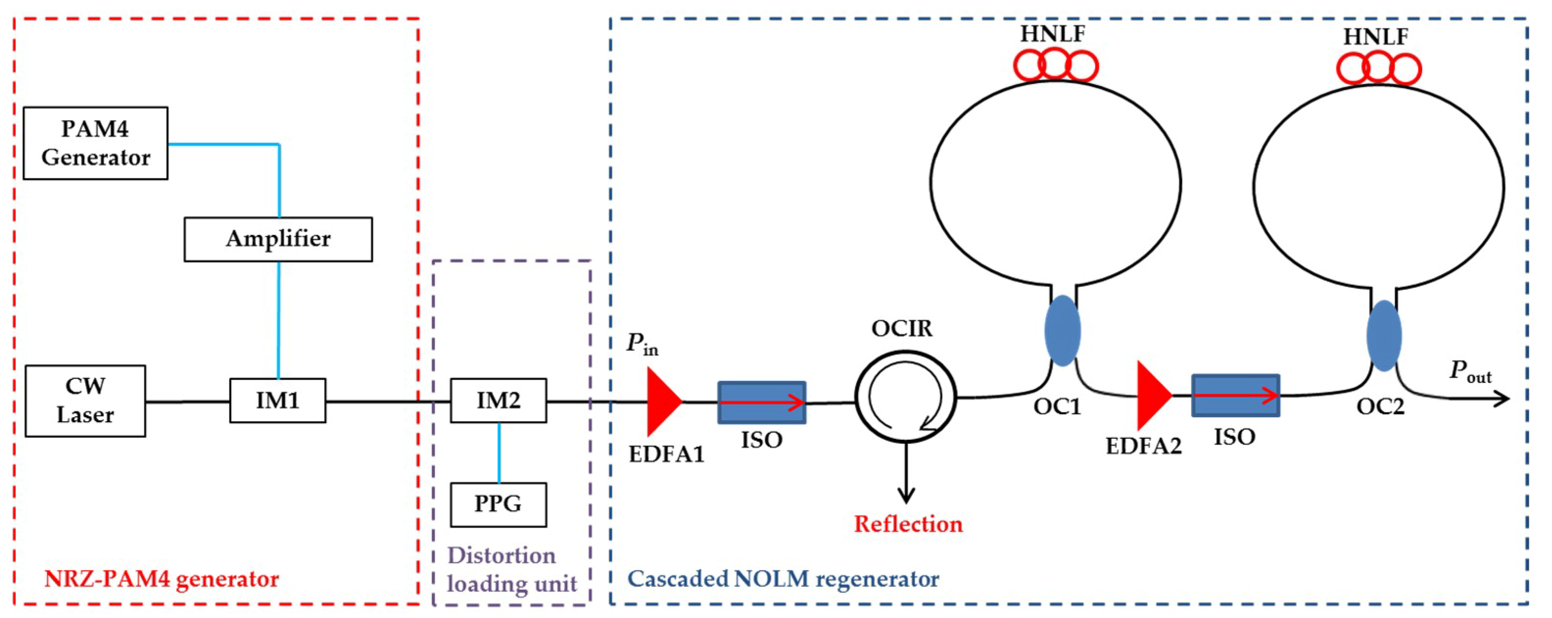
To investigate the regenerative performance we carried out the numerical simulation through the OptiSystem platform. The schematic diagram of the whole PAM regeneration system is shown in Figure 5. The signal is modulated by an intensity modulator 1(IM1) and then degraded by an ASE noise source. An optical isolator (ISO) is used to prevent unwanted reflected light. After an Erbium-doped fiber amplifier 1 (EDFA1), the signal power is boosted to match the optimal regenerative level. Figure 6 gives the level distribution of input and output signal and the simulated waveforms of the PAM signals before and after regeneration. When a degraded PAM-4 signal with the SNR of 20.5 dB is input to the cascaded NOLM-based regenerator, the numerical simulation shows that the NRRs of the four levels are, respectively, 27.11 dB, 18.10 dB, 25.14 dB and 16.65 dB, and the overall Q-factor can be improved by 25.32 dB. The relationship of NRR corresponding to different input SNR is analyzed as shown in Figure 6c. The signal quality improvement can be observed at every input SNR value. The maximal NRR over 30 dB is achieved demonstrating extremely high noise suppression capability by the proposed cascaded NOLM regenerator. The better performance is obtained when the input SNR is larger than 20 dB because the flat power response achieved around WPs, see in Figure 4. Although the noise suppression becomes weaker for the lower SNR, we can still get the NRR improvement of more than 10 dB.
We also test the bit error rate (BER) versus input SNR when the proposed regenerator located in the middle of the transmission link. To give a performance comparison we test the transmission results in an un-regenerative link, i.e., bypassing the regenerator in the inset of Figure 7. Figure 7 depicts the BER improvement achieved at every input SNR points, which confirms the regeneration behavior obtained by the proposed cascaded two-NOLMs subsystem. We observe a 2.69 dB SNR improvement at lg(BER) = −3, 1.69 dB higher than the conventional PAM-4 regenerator [12].
By appropriately designing the structure parameters of two NOLMs in series, we can also obtain a PAM-8 regenerator with ρ = 0.989 and ρ = 0.975 , whose optimal WPs correspond to the eighth level (first stage) and the fourth level (second stage), respectively. The inter-stage matching amplifier has a gain of 1.62 dB. To reduce the operational power we double the nonlinear coefficient γ compared to the former discussion. Figure 8a shows the simulated waveforms of the PAM-8 signals before and after regeneration, in which the input SNR is 20.86 dB. Numerical simulation shows that the Q-factor improvement is up to 21.18 dB and the noise over all eight levels can be suppressed to certain extent, with NRRs of 15.22 dB, 19.57 dB, 25.56 dB, 31.22 dB, 28.27 dB, 25.21 dB, 23.19 dB, and 21.51 dB, respectively. The transmission system of PAM-8 with and without regenerator is also tested as shown in Figure 8b. The BER results in the cascaded-NOLM transmission link are significantly lower than the un-regenerative case, achieving over 3.04 dB improvement. Comparing with the PAM-4 case, the better transmission performance is obtained by using the higher-order modulated format, confirming the regeneration results in other scheme [8,20].
Furthermore, we carry out the cascaded transmission test by placing the proposed regenerator in each 80 km-fiber span, the system scheme depicted in 
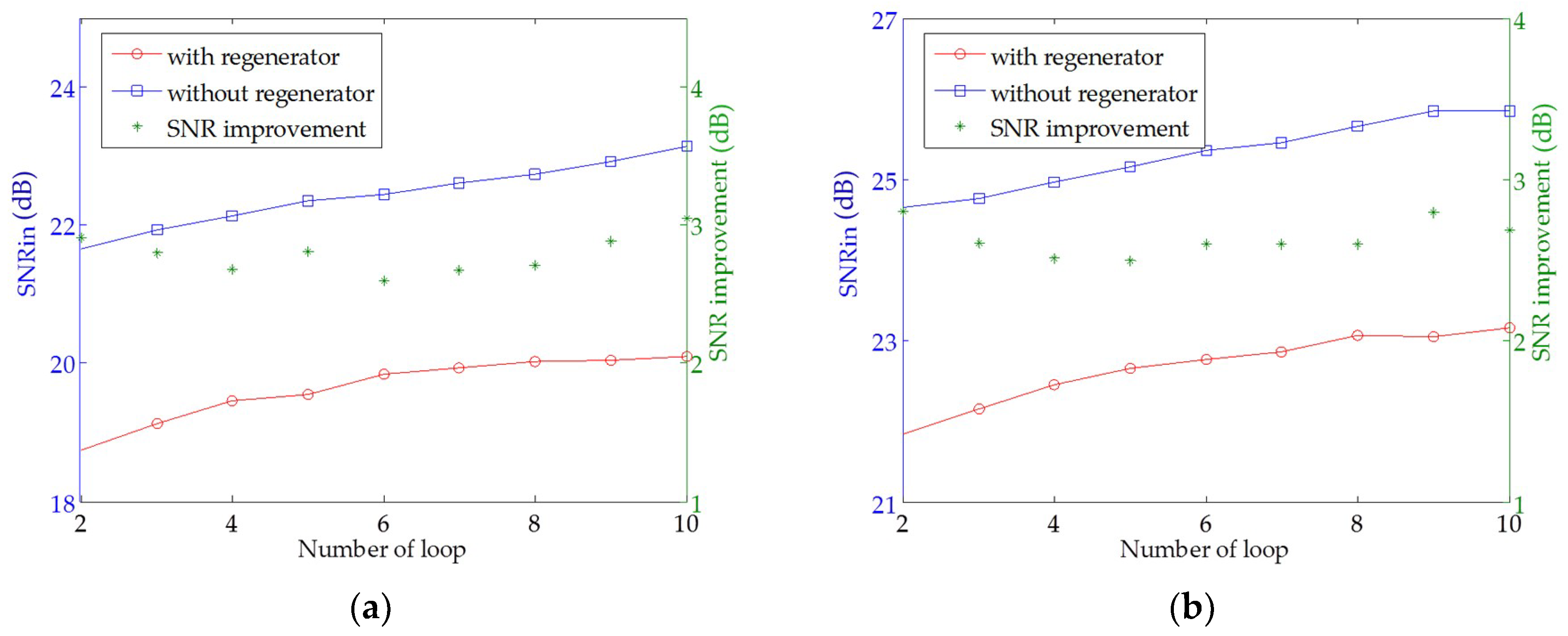
Figure 9. In the span, the EDFA is used to compensate the fiber loss and also introduces the ASE noise consequently. We sweep the input SNR of the PAM-4 signal at a fixed transmission distance, i.e., a fixed loop number N, and collect the required input SNR, i.e., SNRin, corresponding to the output BER of lg(BER) = −3. Then, we plot the dependence of the required SNRin on the number of loop, as depicted in Figure 10a. The red line and the blue line correspond to the left coordinate axis, and the green symbol corresponds to the right coordinate axis. When there is no all-optical regenerator in the transmission link, i.e., an un-regenerative case, the required input SNR becomes even higher with the increase of the loop number N due to the accumulation of ASE noise. For the loop number of 10, i.e., 800 km fiber transmission, we calculated the required input SNR of around 23 dB, close to the input SNR of 26dB demonstrated in a PAM-4 800 km-fiber transmission experiment [21]. After placing the proposed cascade-NOLM regenerator in each span, the amplitude noise is effectively suppressed in the regenerative range, and consequently a lower SNR is needed for the regenerative transmission link, see the red-circular mark in Figure 10a. The SNR improvement of around 2.79 dB is observed by comparing the un-regenerative and regenerative links. We also investigated the transmission performance of PAM-8 signal with or without cascaded-NOLM regenerator; results are depicted in Figure 10b. The similar behavior is observed as the PAM-4 case. Almost the same SNR improvement, i.e., 2.63 dB for PAM-8 signals, was obtained because of the optimized multilevel amplitude regeneration achieved in the cascaded-NOLM scheme.
The amplitude regeneration of PAM-4 or PAM-8 signals has been demonstrated using the cascaded NOLM regenerator. In principle, more NOLMs are necessary for higher-order PAM signals. The common design method is summarized as follows: (1) setting the optimal WPs for all NOLMs in series by optimizing the coupler’s splitting ratio from high to low levels; (2) calculating the gains of all inter-stage matching optical amplifiers; (3) optimizing the NPTF and NDG curves for the cascaded NOLM-based regenerator; (4) determining the regenerative WPs and the dynamic ranges for PAM signal; and (5) simulating the regeneration performance for verification.

5. Conclusions

By analyzing the PAM regeneration properties of single NOLM-based regenerators, we put forward the cascaded NOLM scheme with an inter-stage matching amplifier for high-order PAM signal. The optimal WP for every NOLM in series can be changed by adjusting the coupler’s splitting ratio, and the PAM-4 and PAM-8 regenerations haven been demonstrated in the optimized NOLM structure. Numerical simulation gives the amplitude noise suppression happened on each level and obtains the NRR improvement of over 30 dB. Furthermore, the regenerative transmission link with the proposed cascaded NOLM scheme can perform a 3.04 dB SNR enhancement for the PAM-8 signal. Compared to the conventional regenerator scheme, a 1.69 dB SNR gain is achieved in the cascaded NOLM due to the flat power response within the regenerative range.

Author Contributions

conceptualization, B.G. and B.W.; methodology, B.G. and B.W.; software, B.G.; validation, B.G., B.W. and F.W.; formal analysis, B.G. and B.W.; investigation, B.G.; resources, B.W. and K.Q.; data curation, B.G.; writing—original draft preparation, B.G. and B.W.; writing—review and editing, B.G., B. W. and F.W.; visualization, B.G.; supervision, B.W. and K.Q.; project administration, B.W. and K.Q.; funding acquisition, B.W. and K.Q. All authors have read and agreed to the published version of the manuscript.

Funding

This research was funded by the National Science Foundation (NSFC) (61671108 and 61975027), the General Project of Sichuan Provincial Education Department (18ZB0235) and the Marie Skłodowska-Curie Action (701770-INNOVATION).

Conflicts of Interest

The authors declare no conflict of interest.

References

  1. Slavík, R.; Parmigiani, F.; Kakande, J.; Lundström, C.; Sjödin, M.; Andrekson, P.A.; Weerasuriya, R.; Sygletos, S.; Ellis, A.D.; Grüner-Nielsen, L.; et al. All-optical phase and amplitude regenerator for next-generation telecommunications systems. Nat. Photonics 2010, 4, 690–695. [Google Scholar] [CrossRef]
  2. Perentos, A.; Fabbri, S.; Sorokina, M.; Phillips, I.D.; Turitsyn, S.K.; Ellis, A.D.; Sygletos, S. QPSK 3R regenerator using a phase sensitive amplifier. Opt Express 2016, 24, 16649–16658. [Google Scholar] [CrossRef] [PubMed] [Green Version]
  3. Karinou, F.; Prodaniuc, C.; Stojanovic, N.; Ortsiefer, M.; Daly, A.; Hohenleitner, R.; Kögel, B.; Neumeyr, C. Directly PAM-4 Modulated 1530-nm VCSEL Enabling 56 Gb/s/λ Data-Center Interconnects. IEEE Photonics Technol. Lett. 2017, 27, 1872–1875. [Google Scholar] [CrossRef]
  4. Al-Fares, M.; Loukissas, A.; Vahdat, A. A scalable, commodity data center network architecture. ACM SIGCOMM Comput. Commun. Rev. 2008, 38, 63–74. [Google Scholar] [CrossRef]
  5. Bogoni, A.; Ghelfi, P.; Scaffardi, M.; Potì, L. All-Optical Regeneration and Demultiplexing for 160-Gb/s Transmission Systems Using a NOLM-Based Three-Stage Scheme. IEEE J. Sel. Top. Quantum Electron. 2004, 10, 192. [Google Scholar] [CrossRef]
  6. Ghelfi, P.; Bogoni, A.; Scaffardi, M.; Ponzini, F.; Porzi, C.; Potì, L. Performance Computation of a 160 Gbit/s NOLM-Based 3-Stage All-optical Regenerator. In Proceedings of the Conference on Lasers and Electro-Optics, San Francisco, CA, USA, 16–21 May 2004. [Google Scholar]
  7. Roethlingshoefer, T.; Onishchukov, G.; Schmauss, B.; Leuchs, G. All-Optical Simultaneous Multilevel Amplitude and Phase Regeneration. IEEE Photonics Technol. Lett. 2014, 26, 556–559. [Google Scholar] [CrossRef]
  8. Sorokina, M. Design of multilevel amplitude regenerative system. Opt. Lett. 2014, 39, 2499–2502. [Google Scholar] [CrossRef] [PubMed] [Green Version]
  9. Long, Y.; Wang, A.; Zhou, L.; Wang, J. All-optical wavelength conversion and signal regeneration of PAM-4 signal using a silicon waveguide. Opt. Express 2016, 24, 7158–7167. [Google Scholar] [CrossRef] [PubMed]
  10. Wen, F.; Sygletos, S.; Tsekrekos, C.P.; Zhou, X.; Geng, Y.; Wu, B.; Qiu, K.; Turitsyn, S.K. Multilevel power transfer function characterization of nonlinear optical loop mirror. In Proceedings of the 19th International Conference on Transparent Optical Networks (ICTON), Girona, Spain, 2–6 July 2017. [Google Scholar]
  11. Wen, F.; Tsekrekos, C.P.; Zhou, X.; Wu, B.; Zhu, M.; Zhang, J.; Qiu, K.; Turitsyn, S.K.; Sygletos, S. All-optical multilevel regeneration in nonlinear optical loop mirror. In Proceedings of the 16th International Conference on Optical Communications and Networks (ICOCN), Wuzhen, China, 7–10 August 2017. [Google Scholar]
  12. Wen, F.; Tsekrekos, C.P.; Geng, Y.; Zhou, X.; Wu, B.; Qiu, K.; Turitsyn, S.K.; Sygletos, S. All-optical multilevel amplitude regeneration in a single nonlinear optical loop mirror. Opt. Express 2018, 26, 12698–12706. [Google Scholar] [CrossRef] [PubMed]
  13. Guo, B.; Wen, F.; Wu, B.; Sun, F.; Qiu, K. All-optical multilevel amplitude regeneration based on polarization-orthogonal continuous-wave-light-assisted nonlinear-optical loop mirror (PC-NOLM) subsystem. IEEE Access 2019, 7, 149666–149671. [Google Scholar] [CrossRef]
  14. O’Neill, A.W.; Webb, R.P. All-optical loop mirror switch employing an asymmetric amplifier/attenuator combination. Electron. Lett. 1990, 26, 2008–2009. [Google Scholar] [CrossRef]
  15. Bulow, H.; Veith, G. Polarisation-independent switching in a nonlinear optical loop mirror by a dual-wavelength switching pulse. Electron. Lett. 1993, 29, 588–589. [Google Scholar] [CrossRef]
  16. Schmieder, D.; Swart, P.L. Serial and parallel arrangements of NOLM and NALM loop mirrors. Chin. Opt. Lett. 2005, 3, S109–S114. [Google Scholar]
  17. Pottiez, O.; Ibarra-Escamilla, B.; Kuzin, E.A. Large amplitude noise reduction in ultrashort pulse trains using a power-symmetric nonlinear optical loop mirror. Opt. Laser Technol. 2009, 41, 384–391. [Google Scholar] [CrossRef]
  18. Doran, N.J.; Wood, D. Nonlinear-optical loop mirror. Opt. Lett. 1988, 13, 56–58. [Google Scholar] [CrossRef] [PubMed]
  19. Hasegawa, T.; Nagasima, T.; Sugimoto, N.; Kikuchi, K. Bismuth-based extra-high nonlinear optical fiber. In Proceedings of the Conference on Lasers and Electro-Optics, Baltimore, MD, USA, 22–27 May 2005. [Google Scholar]
  20. Sorokina, M.; Sygletos, S.; Ellis, A.; Turitsyn, S. Regenerative Fourier transformation for dual-quadrature regeneration of multilevel rectangular QAM. Opt. Lett. 2015, 40, 3117–3120. [Google Scholar] [CrossRef] [PubMed]
  21. Zhang, J.; Xia, L.; Zhu, M.; Hu, S.; Xu, B.; Qiu, K. Fast remodeling for nonlinear distortion mitigation based on transfer learning. Opt. Lett. 2019, 44, 4243–4246. [Google Scholar] [CrossRef] [PubMed]
Figure 1. Nonlinear optical loop mirror (NOLM).
Applsci 10 00206 g001
Figure 2. Normalized PTF curves for (a) ρ = 0.97 and (b) ρ = 0.92 .
Applsci 10 00206 g002
Figure 3. The variations of the step power, the WP and the dynamic range with the coupler’s splitting ratio.
Applsci 10 00206 g003
Figure 4. The NPTF and NDG curves for a PAM-4 regenerator with two NOLMs.
Applsci 10 00206 g004
Figure 5. The schematic diagram of the PAM regeneration system.
Applsci 10 00206 g005
Figure 6. (a)The level distribution of input and output signal; (b) waveforms of PAM-4 signals before and after regeneration and (c) the relation curve between input SNR and NRR.
Applsci 10 00206 g006
Figure 7. BER and SNR of PAM4 transmission system with and without NOLM.
Applsci 10 00206 g007
Figure 8. (a) The input and output waveforms of PAM-8 signals of regenerator; (b) BER and SNR of PAM-8 transmission system with and without NOLM.
Applsci 10 00206 g008
Figure 9. Scheme of the cascaded transmission test system.
Applsci 10 00206 g009
Figure 10. (a) Required input SNR of PAM-4 transmission links with or without the cascaded-NOLM regenerator; (b) required input SNR of PAM-8 transmission links with or without cascaded-NOLM regenerator.
Applsci 10 00206 g010

