Technical Note

Advanced Automatic Welding System for Offshore Pipeline System with Seam Tracking Function

Precision Manufacturing & Control R&D Group, Korea Institute of Industrial Technology, Busan 46938, Korea
*
Author to whom correspondence should be addressed.
Appl. Sci. 2020, 10(1), 324; https://doi.org/10.3390/app10010324
Submission received: 4 December 2019 / Revised: 26 December 2019 / Accepted: 27 December 2019 / Published: 1 January 2020
(This article belongs to the Section Mechanical Engineering)

Abstract

:
Automatic welding technology is a solution to increase welding productivity and improve welding quality in offshore pipe welding. To increase welding productivity, it is necessary to save time during the assembly/disassembly of the guide track from the welding carriage and pipe to move the next station. The guide track consists of a pneumatic system that does not separate the welding carriage, and two welding carriages operate on a half-pipe joint to increase productivity. These welding carriages automatically operate under the controller command. An automatic welding system consists of a DC motor module, a step motor module, a welding control module, a welding monitoring module, and a central control module. The control systems incorporate control modules and transmit commands to each module for an automatic welding system. In order to minimize the inevitable misalignment between the centerline of the welding seam and the welding torch for each welding pass, a moving average algorithm for seam tracking is proposed, which was proven to be suitable for the root pass, filling pass, and cap pass. Welding experiments were also carried out to verify the validity of the weld seam tracking system.

1. Introduction

An automatic welding system has the advantages of low labor intensity, good welded joint appearance, and high-speed welding in the offshore pipeline industry [1,2,3,4,5,6]. A welding system in pipeline construction must be capable of working in harsh environments with minimal maintenance intervention. The equipment should embrace modern technology, but it should be easy to set up by the operator. From the perspective of offshore pipeline projects, productivity and reliability are the most essential features of an automatic welding system. Pipe welding in many industrial applications, such as oil drilling platforms and chemical factories, must be handled by an automatic welding machine because of the precision needed to avoid a hazardous leak. An automatic welding system should offer high-quality welding performance for a long period of time and not break down.
If the water is deep, the pipe can be installed on the seafloor using several methods. The main ways that subsea pipes are laid include the S-lay and J-lay method, as shown in Figure 1. In the S-lay method, the pipe joints are welded together onboard the vessel in a horizontal production line. The seagoing pipe is supported by a stinger to control the radius when the pipe bends towards the seabed. Due to the high production rate and the possibility of installing pipes, the S-lay method is extremely suitable for pipe installation in shallow and intermediate waters. The J-lay method is suitable for deep water because the pipe leaves the lay system in the vertical position, and the pipeline is bent while arriving at the seabed. This reduced amount of bending is beneficial for installing pipelines that are sensitive to fatigue. The J-lay method has a relatively low production rate due to the single position welding of the pipe. To ensure the competitiveness of offshore pipeline laying, it is necessary to maintain production balance among the welding processes, minimize the work process time, and ensure perfect welding quality. Since the work process is performed on a barge floating on the sea, working conditions are more difficult than those on land. Moreover, it is difficult to accurately obtain the various automated pieces of equipment used in pipeline work due to their high cost. After aligning pipes with an internal clamp and finishing construction work, more time is spent on repetitive work, which separates the welding carriage with loosening a screw in guide track independently in a conventional welding system. There are two different situations where automatic welding machines are used. Semi-automatic welding uses a pre-programmed automatic welding machine, but the parts are loaded onto the welding bench by an operator who arranges them and switches on the welding machine until the weld is completed. The operator then removes the finished workpiece and repeats the process as many times as necessary. Fully automatic welding removes the human element, except as an overall observer to make sure the machines are running properly. In these set-ups, the parts and finished workpieces are moved by other machines, such as conveyor belts, and the welding operation is continuous over a large number of individual pieces.
Welding productivity is also greatly influenced by the geometry of the weld joint. In narrow groove, welding time can be minimized by reducing the amount of welding, but the narrow groove can increase the welding defect, such as a lack of fusion on sidewalls [7,8]. To get the most out of narrow groove welding, the welding system incorporates an automatic seam tracking, and an without operator intervention is essential to compensate for the fit-up condition. Since automatic pipe welding systems incorporate tandem welding processes to increase production, but multiple arc behavior makes it difficult to observe the weld centerline, so an automatic seam tracking system is necessarily required [9,10,11,12]. If the calculation of the correction value for seam tracking is incorrect, the weld centerline of the weaving motion deviates from the weld centerline. When the welding torch is brought close to the sidewall, an undercut welding defect occurs. On the other sidewall, the welding torch position is far away from the weld groove wall, and incomplete penetration occurs. This study has developed an advanced automatic welding system that increases productivity and saves time using a pneumatic system. The guide track with a pneumatic system is an integral part of the welding carriage as it automatically connects the pipe joints. The automatic welding system communicates with each control module for automatic welding and commands the welding carriage. The arc sensor was developed to achieve high seam tracking accuracy to fully automate the welding system.

2. The Automatic Welding System

The automatic welding system consists of welding machines, a welding controller, and a guide track that performs the motion needed to weld the carriages. The automatic welding system is illustrated in Figure 2. The welding controller sends its control commands to the welding carriage. The welding carriage consists of dual torches to save welding time and increase productivity. The two welding carriages perform along half the guide track. The construction of a wire feeder box is shown in Figure 3 and consists of a gas flow meter, a wire feeder calibration, a welding wire, and voltage and current sensors. The gas flow meter measures the constant flow rate during welding.

3. Characteristics of the Automatic Welding System
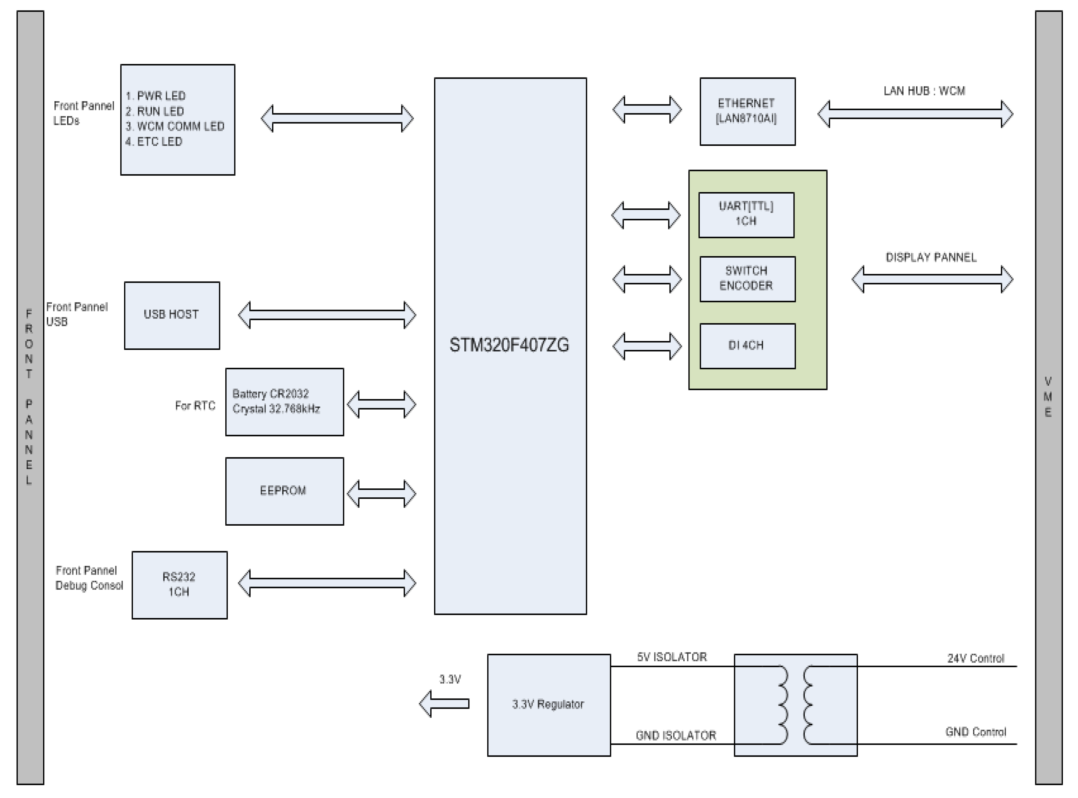
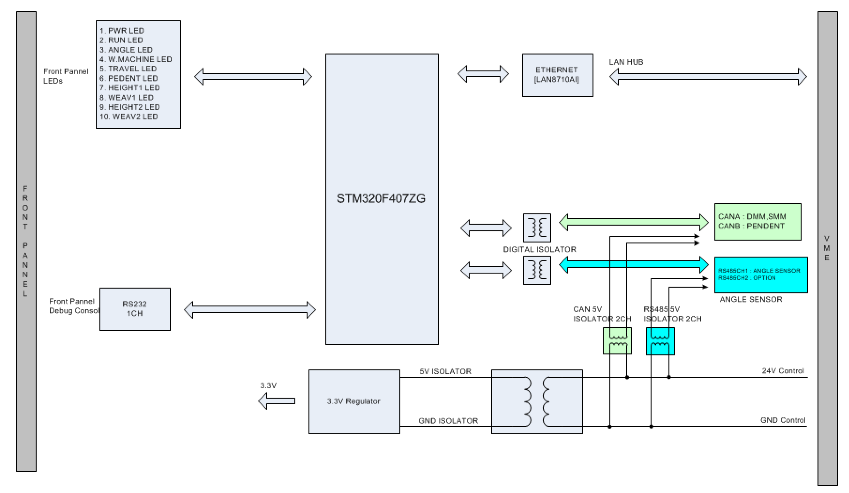
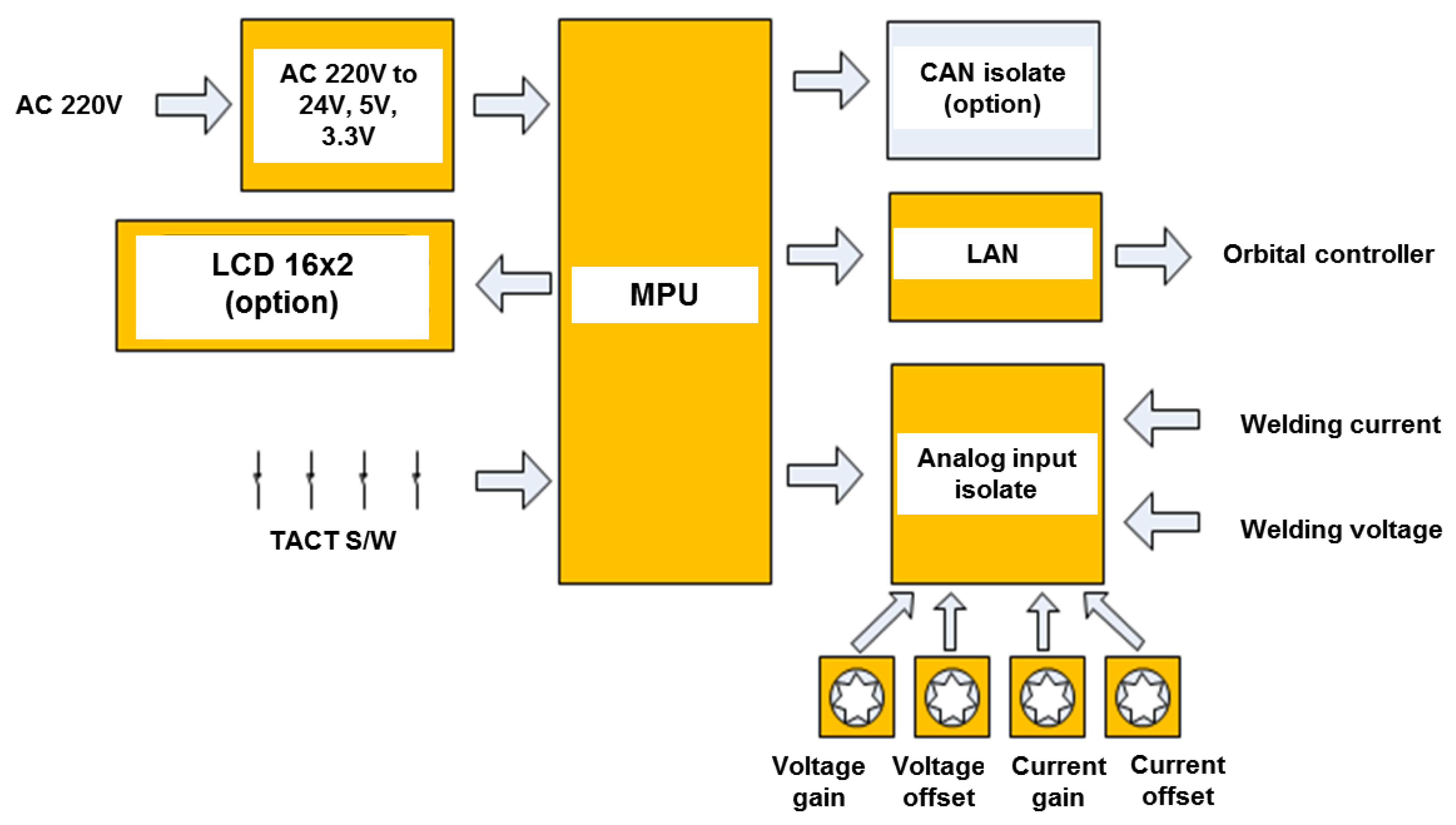
3.1. Control System

The automatic welding system consists of the DC motor module (DMM), the step motor module (SMM), the welding control module (WCM), the welding monitoring module (WMM), and the central control module (CCM) as shown in Figure 4. Each module was the integration of the control module into the automatic welding system and sends a command to the welding carriage.

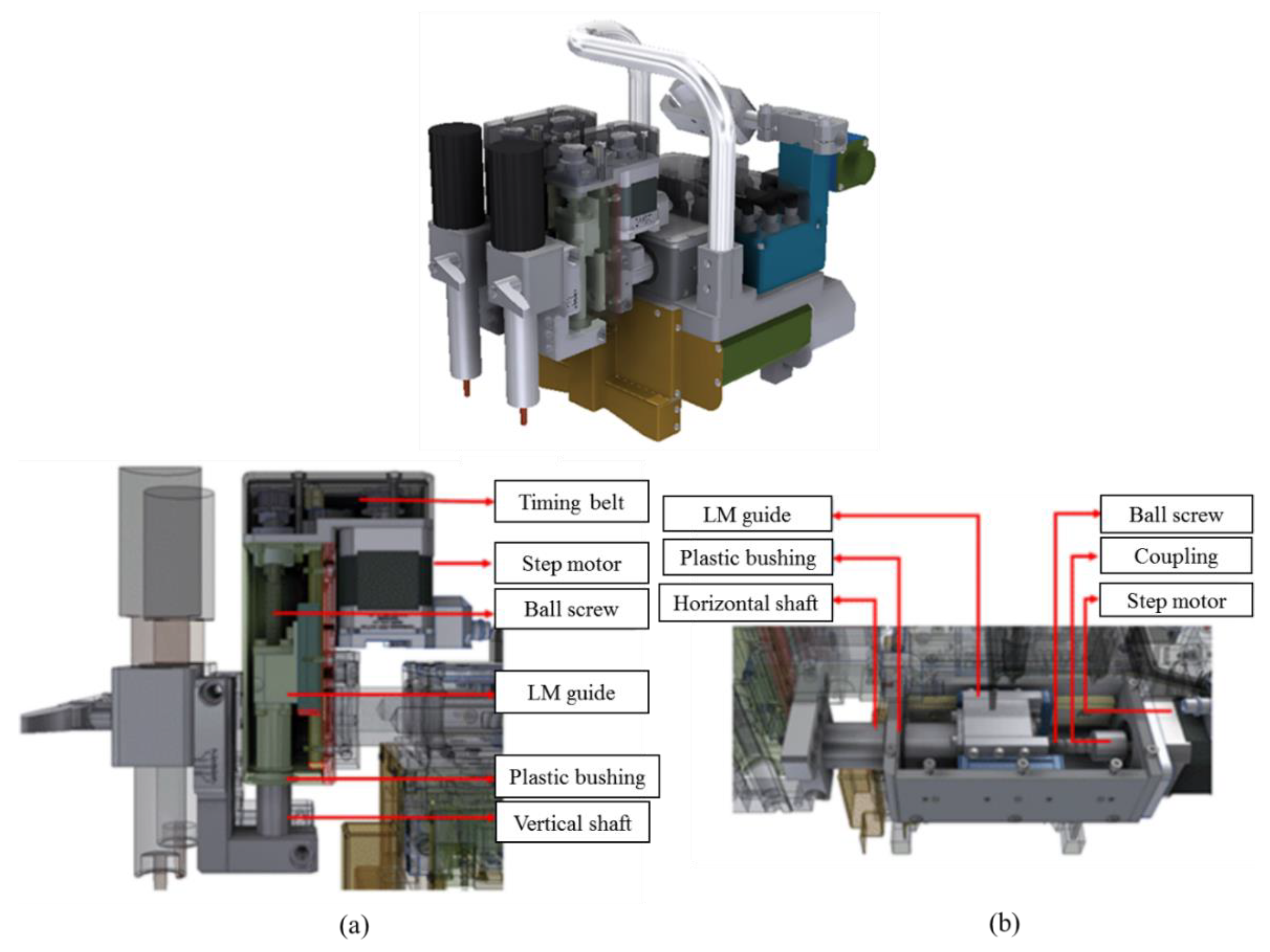
3.2. Welding Carriage

The welding carriage operates in the circumference direction of the pipe and performs the motion of the welding torches. The welding carriages are dependent on the servo motor and move along the guide track. The step motor controller (SMC) controls the movement of a welding torch. The structure of the welding carriage is shown in Figure 5.

3.3. Control of the SMM

The SMM communicates with the SMC. Four SMC boards control the four welding torches on the half welding system. A heat sink bar was installed to prevent overheating, as shown in Figure 6.

3.4. Control of the CCM

The electronic control equipment receives information from the remote pendant and transmits the control commands to the welding carriages. A block diagram of the CCM is shown in Figure 7. The user can set the welding conditions in the data base manager (DBM), as shown in Figure 8, and sends commands to the welding carriages. From the set values, the welding carriage performs welding on pipes whenever the welding situation changes based on the sequence index. The information of the DBM corresponds to the selected program transferred from the remote pendant to the WCM. The WCM, DMM, and SMC receive the status of each module in the welding controller.

3.5. Control of the WCM

The WCM controls the welding carriage during the welding process. The welding carriage receives the welding settings from the DBM, as planned by the user. The WCM receives the current position of the welding carriage from its angle sensor at 100 ms intervals and compares the angle values that are defined in each sequence of the DBM. After transmitting the control command, the DMM and SMC perform welding movements using set values in the DBM. The block diagram of the WCM is shown in Figure 9.

3.6. Control of WMM

For acquiring the welding signals, a voltage sensor was connected to the torch line (+) and ground (−) position, and a current sensor was used as a Hall sensor in WMM. The analog input is automatically adjusted for gain and offset, as shown in Figure 10.

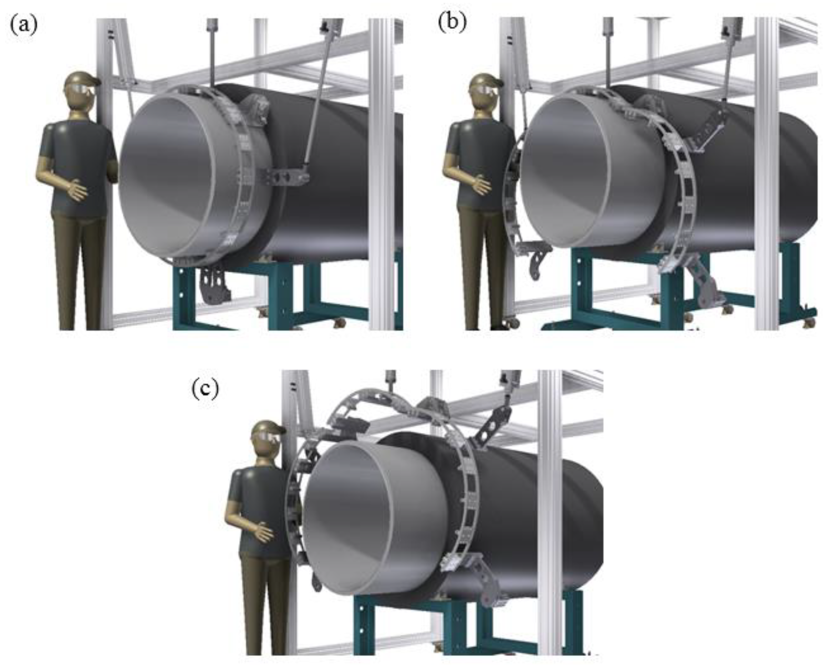
4. Integrated Welding Carriage with a Guide Track

The structure of the guide track is shown in Figure 11. The pneumatic guide track automatically assembles the pipe with a locking device. To fix the pipe firmly, a vertical guide is used. The spring blocks that can adjust the tension force by which the guide track is tightly fixed to the outer surface of the pipe. A locking device tightly fixes the pipe to the pipe position. The guide track adjusts to the pneumatic system without separating the welding carriage, as shown in Figure 12.

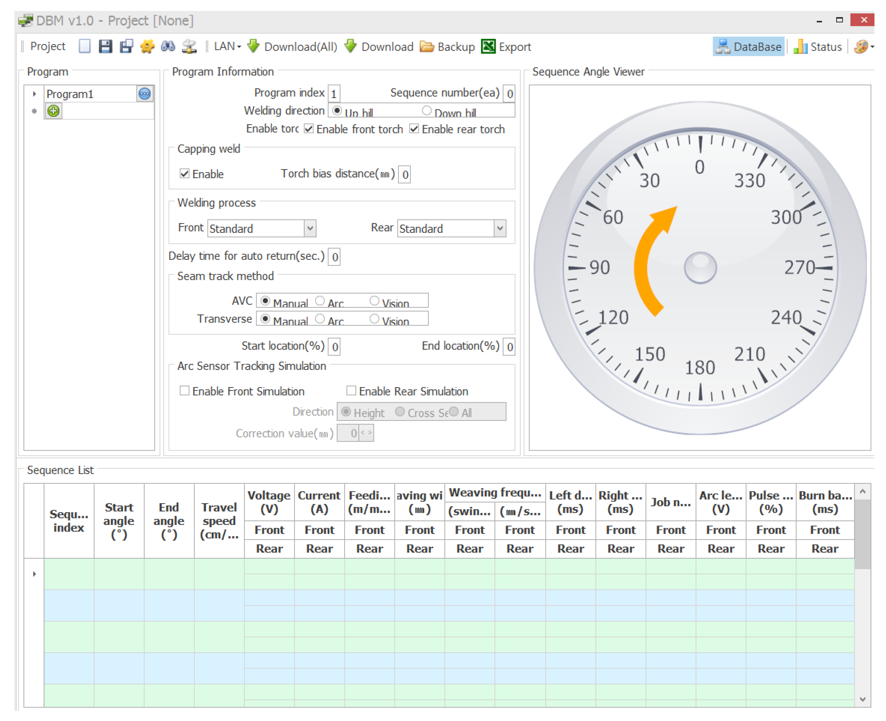
5. Application of the Automatic Welding System

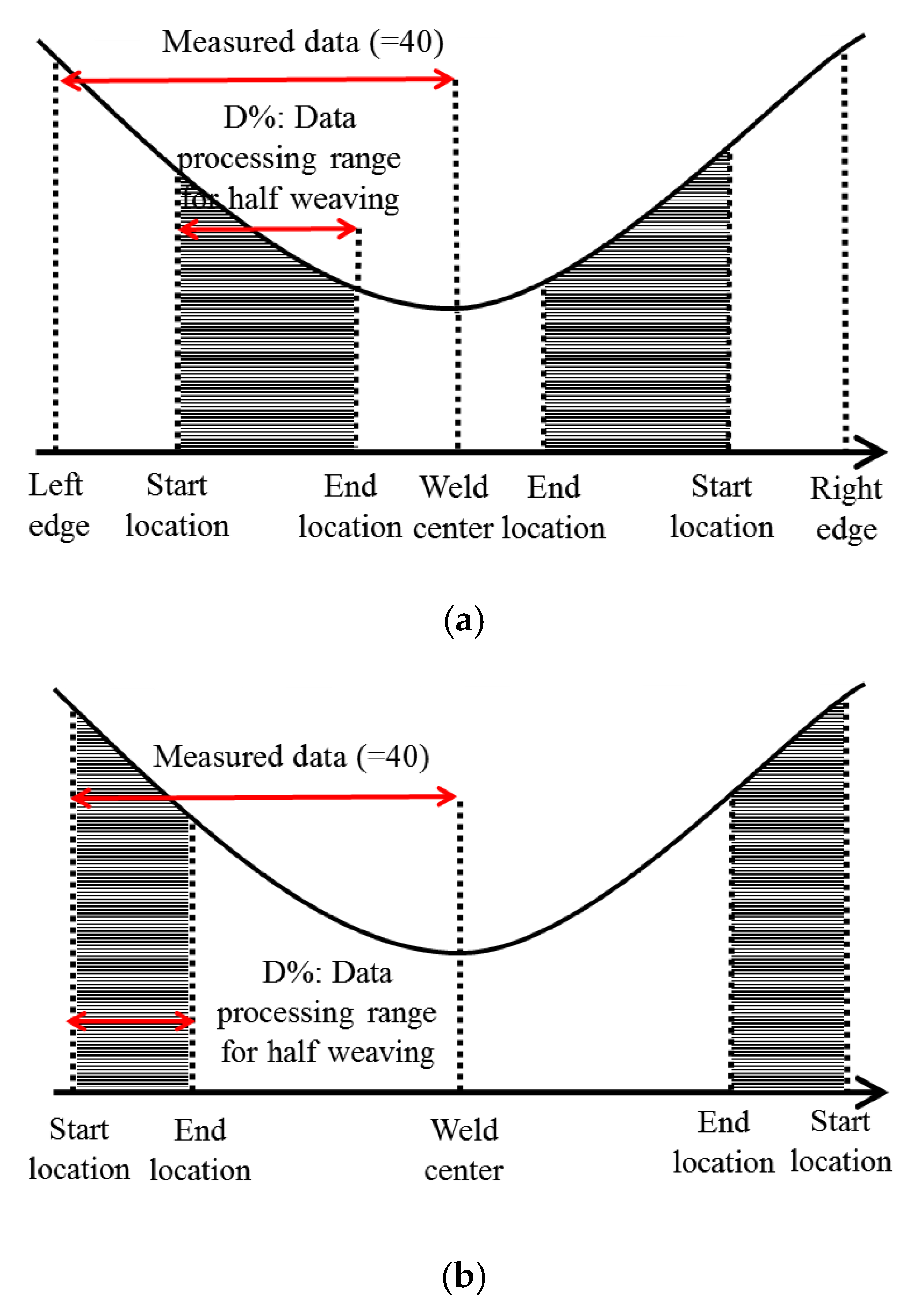
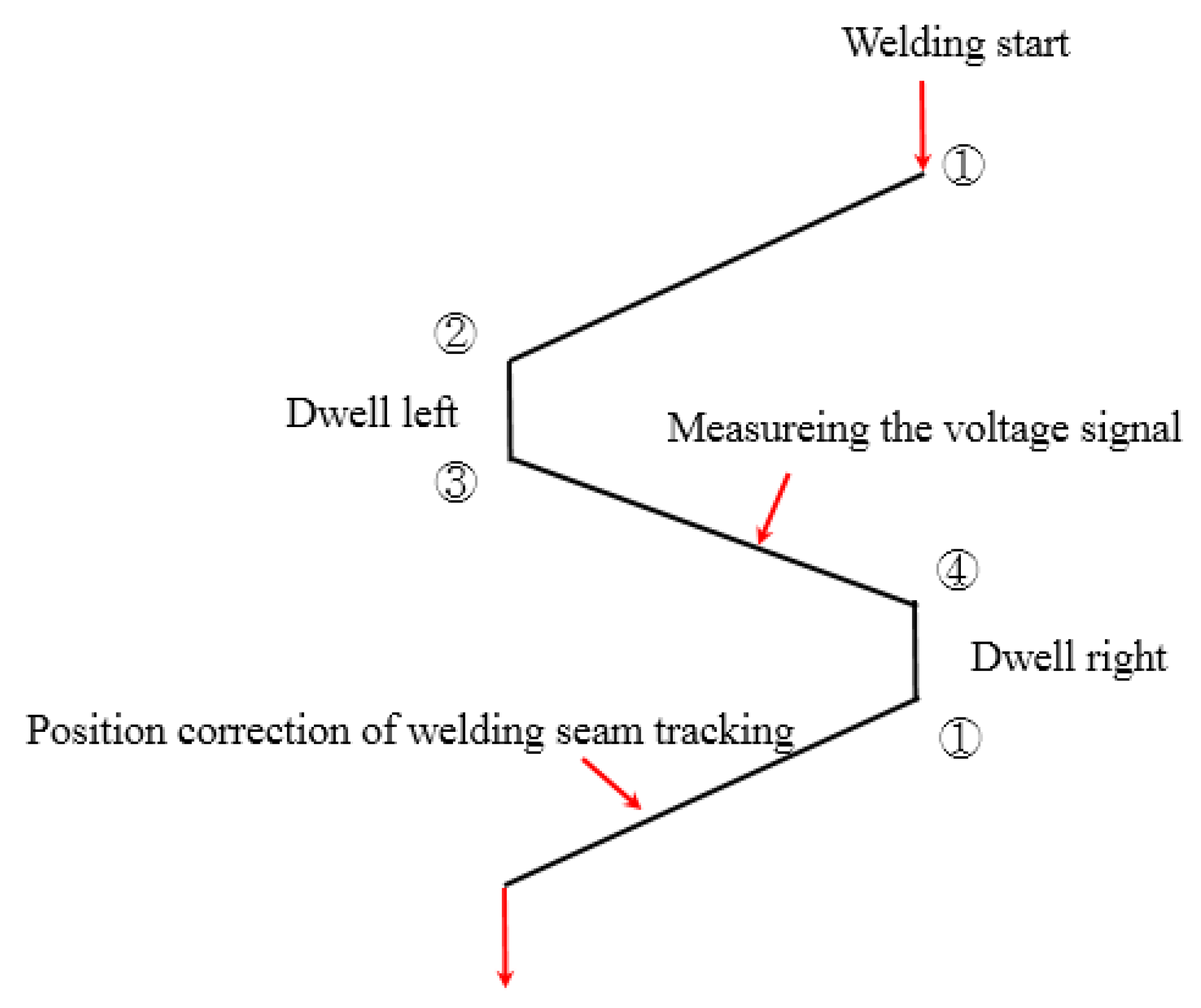
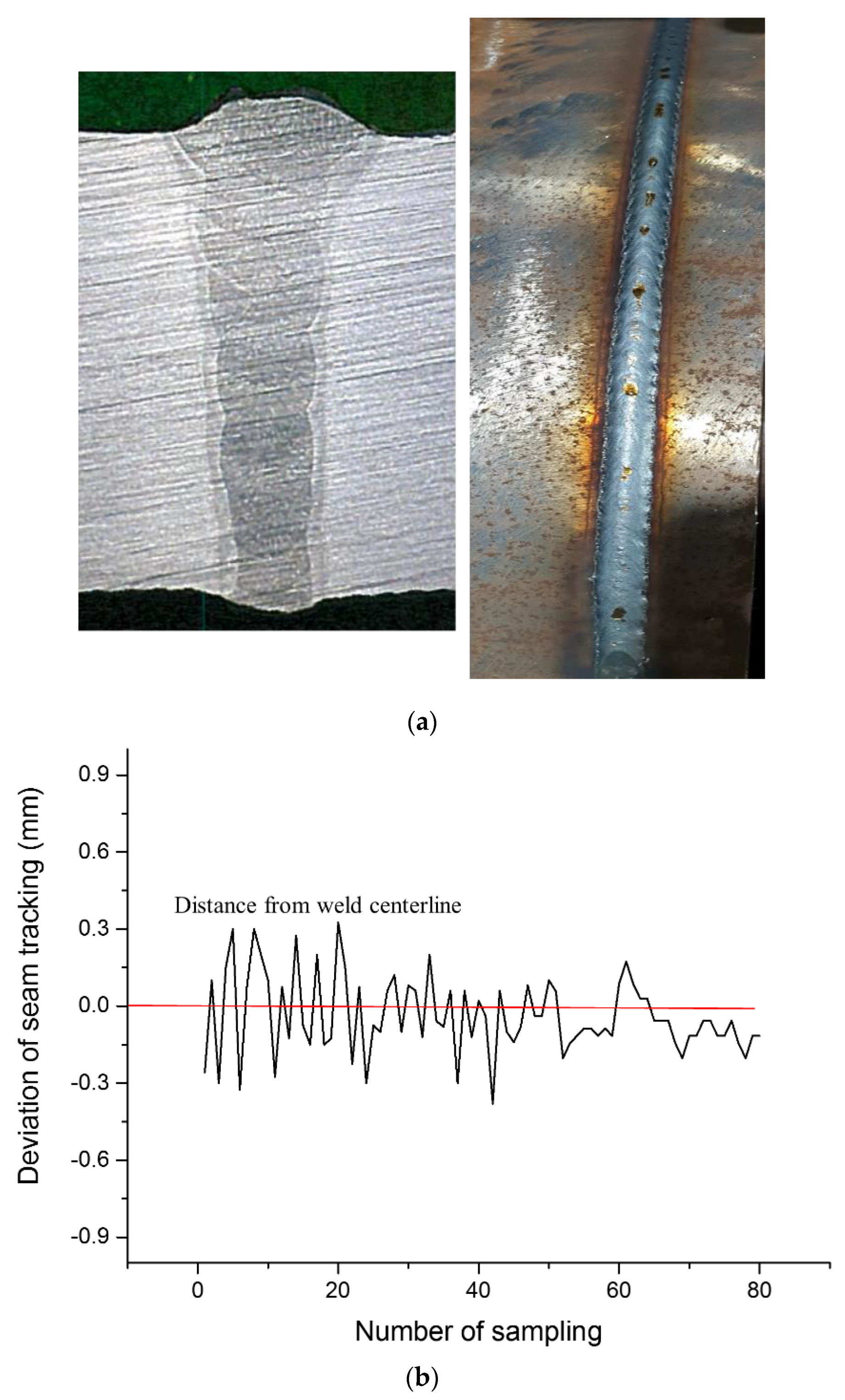
Welding Seam Tracking

The seam tracking automatically welds the weld centerline via signal processing during the welding process. Various types of signal processing algorithms have been developed, such as curve fitting, the integral method, and the moving average [9,10,11,12]. The requirement for a seam tracking algorithm is the measurement of welding signals (voltage or current) and determination of the geometry offset that deviates from the weld centerline. This study conducts a moving average method based on voltage values.
The number of samplings was divided into the measurement of the voltage values in the left (forward) and right (backward) directions, as shown in Figure 13. In consideration of the geometry of the U-groove shape, the selection of the signal section (start location and end location) differently set for stable seam tracking. The signals measured near the arc center is flat because the groove shape at the center position is similar to a flat shape. It means that the seam tracking sensor cannot detect the signal difference between the left and right side during a weaving motion. Hence, the ratio of measuring interval plays an important role in the sensitivity and reliability of the seam tracking sensor.
The average value was calculated and stored as a representative value. The signal section where the measured value suddenly changed according to the shape of the welding groove was excluded from the representative value calculation. The procedure of welding seam tracking is shown in Figure 14. Table 1 shows the procedure of welding seam tracking in each sequence with the control modules.
The moving average is calculated in Equation (1):
V a l u e a ( k ) = { ( f a c t o r 1 ) × V a l u e a ( k 1 ) + V a l u e m ( k ) } f a c t o r
The moving average method has the advantage of changing factors to easily determine the cut off frequency, and this paper used a digital low-pass filter in the voltage signal. The forward-moving average (FMA) method is calculated in Equation (2), and the sampling number is set to a number from 1 to 80. The backward moving average (BMA) method is calculated in Equation (3), and the sampling number is set from 80 to 1 in Equation (3). After calculating the FMA and BMA, the mean value of the moving average is calculated in Equation (4), and the welding signal is shown in Figure 15.
V a l u e f o r w a r d ( k k = 1 ~ 80 ) = { ( a 1 ) × V a l u e a ( k 1 ) + V a l u e m ( k ) } f a c t o r
V a l u e b a c k w a r d ( k k = 80 ~ 1 ) = { ( a 1 ) × V a l u e a ( k ) + V a l u e m ( k 1 ) } f a c t o r
V a l u e m e a n ( k ) = V a l u e f o r w a r d ( k ) + V a l u e b a c k w a r d ( k ) 2
where V a l u e a ( k ) is the averaged value at k step. V a l u e m ( k 1 ) is the averaged value at k 1 step. V a l u e m ( k ) is the measured signal value (voltage) at k step, and a is the moving average factor. To calculate the correction value, the weaving time is calculated during the weaving motion from left to right or right to left. The voltage signals are consecutively measured during a weaving motion. The weaving width is fixed to avoid the abrupt weaving motion. Finally, the correction value for deviations (VL, VR) of the welding seam tracking is transmitted to the weaving motion. The calculation of the correction value is performed in Equation (5). The welding torch from left to right seam tracking function compares the average of the measured signals between the start location and the end location and determines the extent of the left and right deviation of the welding torch according to the signs (+, −) and the value of the result. The maximum correction value should be modified according to the oscillation frequency in order to implement a reliable seam tracking system. In case of high oscillation frequency in root pass welding, the number of corrections can be increased. When the oscillation frequency is low in fill pass welding, the correction frequency is reduced. Therefore, the maximum correction value in the root pass is limited as 0.1 mm and fill pass is limited as 0.2 mm.
D = V L e f t V R i g h t k
where k is a constant in the weld database. V L e f t is the averaged voltage value in data processing range, and V R i g h t is the averaged voltage value in the data processing range. Figure 16 shows a schematic of the U-groove geometry and welding sequence. Table 2 summarizes the experiment condition. The welding time is cut in half compared with the single carriage welding system, and the preparation of weld time for installation is reduced by 1/3. The fusion zone shape was shown in Figure 17a, and the value for the deviation of the weld centerline is ± 0.3   mm in Figure 17b.

6. Conclusions

This paper developed an automatic welding system to increase productivity and improve the welding quality of pipe welding. The automatic welding system consists of the DC motor module, the step motor module, the welding control module, the welding monitoring module, and the central control module. The control systems incorporated control modules and transmitted commands to each module for the automatic welding system. The guide track incorporated a welding carriage using a pneumatic system to save time and increase productivity. The arc sensor was developed to achieve high seam tracking accuracy to increase welding quality. The result of the deviation of the seam tracking was ± 0.3   mm .

Author Contributions

J.-H.P. and H.-S.M. conceived and designed the experiments; J.-H.P. performed the experiments; J.-H.P. and H.-S.M. analyzed the data; H.-S.M. contributed reagents/materials/analysis tools; J.-H.P. wrote the paper. All authors have read and agreed to the published version of the manuscript.

Funding

This research was funded by the development of intelligent marine robot to improve underwater work convenience.

Conflicts of Interest

The authors declare no conflict of interest.

References

  1. Gao, Y.; Zhao, H.; Zhang, H. The application of automatic welding technology in West-to-East gas pipeline project. Oil Gas Storage Transp. 2003, 22, 53–55. [Google Scholar]
  2. Wang, R.; Guo, R.J. Developments of automatic girth welding technology in pipelines. Electr. Weld. Mach. 2011, 41, 53–55. [Google Scholar]
  3. Anxin, H.; Su, X.; Huafeng, S. Current situation of automatic welding of domestic long distance pipelines. Nat. Gas Oil 2006, 24, 12–14. [Google Scholar]
  4. Li Helin, J.L.; Wei, T. High grade line pipe and high pressure transportation: Significant progress of oil & gas transportation pipeline technology in China. China Eng. Sci. 2010, 12, 84–90. [Google Scholar]
  5. Yapp, D.; Blackman, S.A. Recent developments in high productivity pipeline welding. Braz. Manuf. Congr. 2004, 26, 89–97. [Google Scholar] [CrossRef] [Green Version]
  6. Yu, Z.; Zhang, W.; Zhang, Z. Development trend of China’s gas pipeline and relevant technical problems. Oil Gas Storage Transp. 2012, 31, 321–325. [Google Scholar]
  7. Kim, R.-H.; Choi, G.-D.; Kim, C.-H.; Cho, D.-W.; Na, S.-J. Arc characteristics in pulse-GMA welding with acute groove angles. Weld. J. 2012, 91, 101–105. [Google Scholar]
  8. Kim, J.W. A Study on the Analysis of Weld Pool Convection and Seam Tracking by Considering the Arc Length Characteristics in GMA Welding. Ph.D. Thesis, KAIST, Daejeon, Korea, 1991. [Google Scholar]
  9. Moon, H.-S.; Ko, S.-H. Automatic pipeline welding system equipped with six welding carriages, laser vision sensor and arc sensor for offshore pipeline laying. In Proceedings of the ISOPE Conference, Vancouver, BC, Canada, 6–11 July 2008. [Google Scholar]
  10. Moon, H.-S.; Na, S. A study on algorithm for seam tracking by considering weld defects in horizontal fillet welding. Korean Weld. Soc. 1996, 2, 139–141. [Google Scholar]
  11. Khosla, P.K.; Neuman, C.P.; Prinz, F.B. An algorithm for seam tracking applications. Int. J. Robot. Res. 1985, 4, 27–41. [Google Scholar] [CrossRef]
  12. Kim, J.W.; Na, S.J. A study on arc sensor algorithm for weld seam tracking in gas metal arc welding of butt joints. Proc. Inst. Mech. Eng. 1991, 205, 247–255. [Google Scholar] [CrossRef]
Figure 1. Integrated pipe lay systems: (a) S-lay system and (b) J-lay system.
Applsci 10 00324 g001aApplsci 10 00324 g001b
Figure 2. Automatic welding equipment in the pipeline system.
Applsci 10 00324 g002
Figure 3. Construction of the wire feeder box.
Applsci 10 00324 g003
Figure 4. Block diagram of the automatic welding control system.
Applsci 10 00324 g004
Figure 5. Structure of the welding carriage: (a) Vertical view and (b) horizontal view.
Applsci 10 00324 g005
Figure 6. Step motor module (SMM) board block diagram.
Applsci 10 00324 g006
Figure 7. Block diagram of the central control module (CCM).
Applsci 10 00324 g007
Figure 8. The user interface for welding settings using data base manager (DBM).
Applsci 10 00324 g008
Figure 9. Welding control module (WCM) board block diagram.
Applsci 10 00324 g009
Figure 10. Welding monitoring module (WMM) board block diagram.
Applsci 10 00324 g010
Figure 11. Description of the welding guide track system.
Applsci 10 00324 g011
Figure 12. Installation of the guide track for pipe welding with a pneumatic system: (a) Locking the guide track, (b) unlocking the guide track, (c) disassembling the guide track from the pipe and moving to the next station.
Applsci 10 00324 g012
Figure 13. Selection of the signal section for weld seam tracking: (a) Root pass welding, (b) fill pass welding.
Applsci 10 00324 g013
Figure 14. Procedures of welding seam tracking.
Applsci 10 00324 g014
Figure 15. Moving averaged signal (voltage).
Applsci 10 00324 g015aApplsci 10 00324 g015b
Figure 16. Schematic of U-groove shape without root gap: (a) Joint detail and (b) welding sequence.
Applsci 10 00324 g016
Figure 17. Results of welding seam tracking: (a) Welding bead shape with fusion zone and (b) deviation of seam tracking in fill pass welding.
Applsci 10 00324 g017
Table 1. Function of the control module in welding seam tracking.
IndexWeavingWCMWMMSMM
1① → ②Calculation of weaving timeCorrection value for left and right
2② → ③Transmit the measurement of the voltage valueReceive the measurement of voltage
3③ → ④Receive the voltage value and number of samples
4④ → ①Receive the voltage value
Calculate the correction value
Transmit the correction value
Calculate the mean moving average
Transmit the voltage value
Receive the correction value
Table 2. Welding condition.
Pass
No.
Current & PolarityCurrent (A) & Lead/TrailVoltage (V) & Lead/TrailTravel Speed (cm/min)Ocill. Width (mm)Ocill. Frequency [spm]
RootDC (+)Lead: 252Lead: 25.5630.6220
Trail: 246Trail: 24.5
HotDC (+)Lead: 252Lead: 25.5630.6220
Trail: 246Trail: 24.5
Fill 1DC (+)Lead: 247Lead: 25621.8200
Trail: 233Trail: 24.5
Fill 2DC (+)Lead: 243Lead: 25632.7200
StripDC (+)Trail: 237Trail: 25.5622.7200
CapDC (+)Lead: 247Lead: 24.5662.7200
Trail: 233Trail: 24

