Article

A Three-Dimensional Cartesian Mesh Generation Algorithm Based on the GPU Parallel Ray Casting Method

1
State Key Laboratory of Explosion Science and Technology, Beijing Institute of Technology, Beijing 100081, China
2
Institute of Fluid Physics, China Academy of Engineering Physics, Mianyang 621999, China
*
Author to whom correspondence should be addressed.
Appl. Sci. 2020, 10(1), 58; https://doi.org/10.3390/app10010058
Submission received: 24 October 2019 / Revised: 16 December 2019 / Accepted: 16 December 2019 / Published: 19 December 2019
(This article belongs to the Section Mechanical Engineering)

Abstract

:
Robust and efficient Cartesian mesh generation for large-scale scene is of great significance for fluid dynamics simulation and collision detection. High-quality and large-scale mesh generation task in a personal computer is hard to achieve. In this paper, a parallel Cartesian mesh generation algorithm based on graphics processing unit (GPU) is proposed. The proposed algorithm is optimized based on the traditional ray casting method in computer graphics, and is more efficient and stable for large-scale Cartesian mesh generation. In the process of mesh generation, the geometries represented by triangular facets are transformed into a mesh composed of orthogonal hexahedrons. A parallel ray generation method is proposed to reduce the data exchange between the host memory and device memory. A parallel primitives searching method based on lattice grid is adopted to search the triangular facets for intersection calculation between rays and triangles. The parallel Cartesian mesh generation algorithm has been implemented using CUDA library. The performance of parallel Cartesian mesh generation algorithm has been promoted enormously compared with the traditional the sequential algorithm, which is shown in different numerical experiments. Through some tests, the performance of parallel algorithm is analyzed, and the results show that the parallel computing power of the GPU is fully utilized. Finally, examples of Cartesian mesh generation are presented.

1. Introduction

Cartesian mesh has been wildly used in computational fluid dynamics [1,2,3,4], computational explosion mechanics [5], and computer graphics such as collision detection [6,7]. Cartesian mesh is usually used as an approximate discretization for three-dimensional geometry. This kind of numerical mesh is piled up by a variety of orthogonal hexahedrons, and the boundary of meshes which belong to different substances is ladder-shaped as shown in Figure 1. In Figure 1, there are two kinds of substance in a two-dimensional computational domain, which are represented by blueness and whiteness, respectively, and the computational domain containing an ellipse is meshed into the Cartesian mesh. In computational fluid dynamics application, the geometric boundary conditions are discretized into the Cartesian mesh, and physical quantities are assigned on the mesh cells. The value of physical quantities on cells will be updated with the process of computation and regarded as the approximate value of physical quantities in the continuous physical space [8]. In the computer graphics application, the Cartesian mesh generation process is similar with the voxelization, which can be used in collision detection and rendering scenes in three-dimensional games. There is a variety of research about voxelization [9,10,11] in the field of computer games. The proposed algorithm in this paper focuses on the application in hydrodynamics, explosion mechanics, and electromagnetism numerical simulations. In these fields, the number of mesh cells generated is much larger than that in three dimensional computer games and can usually reach 10 10 [12]. Although the real-time is not necessary, the efficiency of the mesh generation strongly influences the efficiency of numerical simulation and the efficient Cartesian mesh generation needs to be paid more attention.
There are two popular algorithms for large-scale Cartesian mesh generation. One is ray casting algorithm, which create a series of rays and compute the intersection between rays and geometries [13]. This method is usually applied to large-scale mesh generation because of its clear and simple procedure. However, the algorithm efficiency needs to be improved because of the large amount of time consumption in geometric intersection calculation. The other one is slicing algorithm [14,15], referring to the thought of rapid prototyping machining [16,17], which cut the geometries using a series of parallel planes to obtain contours in each plane. Then, the Cartesian mesh generation task in three-dimensional space is converted into a similar task in two-dimensional plane. This method can obtain more geometric information in the process of mesh generation. However, the process of topological reconstruction has to be added to slicing algorithm, which leads to an efficiency decline. In addition, a preprocess must be added which makes the algorithm so tedious that the robustness and adaptability of algorithm need to be improved, and the mesh generation process is not conducive to large-scale parallelism. Considering the huge amount of mesh cells in the three-dimensional Cartesian mesh generation for a large-scale sophisticated scene, MacGillivary [18] achieved the trillion Cartesian mesh cells generation using a highly accurate ray-facet intersection test and highly efficient data storage method based on the traditional ray casting algorithm. But this achievement still has details to be improved in efficiency and adaptability, and their algorithm is a sequential algorithm.
The time consumption is the largest limitation of Cartesian mesh generation for large-scale scene. Parallel computation on GPU is potentially the best choice to break through the performance bottleneck. Park and Shin [19] proposed a three-dimensional adaptive Cartesian mesh generation method based on GPU. Schwarz and Seidel [20] proposed a fast parallel surface and solid voxelization based on GPUs, which can discrete the geometry to binary voxels in real time. Their algorithms utilized the octree as the discrete result, which can be used in collision detection applications efficiently. However, the number of mesh cells is too small to be used in numerical simulations for fluid dynamics. The similar works are implemented by Cohenor [21] and Pantaleoni [22]. In the process of mesh generation, most of the efforts are concentrated on the intersection calculation between rays and triangular facets. Thus, fast facets searching method is a keypoint. The K dimensional tree (KD-tree) and the bounding volume hierarchy (BVH) tree are always used for searching geometric primitives in three-dimensional dynamic scene. Shevtsov et al. [23] proposed a parallel ray tracing algorithm to render the scene using parallel KD-tree. Wehr and Radkowski [24] introduced a parallel KD-tree construction method for three-dimensional points on a GPU which employs a sorting algorithm to maintain a high parallelism throughout the construction. The parallel construction of BVH tree on GPU is implemented by Lauterbach and Ganestam [25,26] for scene rendering. In the Cartesian mesh generation algorithm in this paper, the primitive searching is performed in a two-dimensional projection plane, and the positions of primitives in computational domain are not changed. Thus, a lattice grid method [27] is adopted into the Cartesian mesh generation.
In this paper, a parallel Cartesian mesh generation algorithm based on the GPU is proposed. A parallel ray generation method on the GPU is proposed to reduce the data exchange between host memory and device memory in Section 2.2. A primitive searching method based on the lattice grid is adopted to search the triangle facets for intersection calculation between rays and triangles in Section 2.3. Some examples of Cartesian mesh generation are shown in Section 3.1. The performance analysis and comparison between the parallel algorithm and the traditional algorithm is shown in Section 3.2.

2. Materials and Methods

Generally, the ray casting algorithm is the most popular and accurate method for generating Cartesian mesh. The classical ray casting algorithm can generate a large number of mesh cells through a simple procedure, whose advantages also contain higher stability and degree of parallelism. The ray casting algorithm contains three main steps: ray generation, intersection calculation, and property mapping. In the following sections, the parallelization method of each step mentioned above will be introduced, respectively.

2.1. Baseline of Ray Casting Algorithm

All the geometry information needed in the process of mesh generation can be extracted from the STL file, in which the geometry is discretized into triangular facets, and the three-dimensional coordinates and normal vectors of triangular facets are stored [28]. In some slicing algorithms for mesh generation, the redundant information which mainly contains the same coordinate of vertex in STL file must be filtered out and the topological information of geometry must be reconstructed [29]. However, to avoid this disadvantage, the ray casting algorithm in this paper regards all the triangular set T and the normal vector set N in STL file as necessary input information. The destination of Cartesian mesh generation is obtaining three-dimensional data field F through T and N. The value of each element in F is the property flag of each mesh cell. As shown in Figure 2a, the rectangular computational domain contains four geometries. The blue plane ( X Y plane in Figure 2) is the projection plane where rays start. A series of ray starting from the point in projection plane is emitted with the direction of Z dimension. Usually, the largest dimension of three dimensions of the computational domain is selected as the ray direction. The rays cross the whole computational domain and intersect with geometries as shown in Figure 2b. Through the intersection points, the mesh cells are classified into different flags. The collection of flags F is the result of Cartesian mesh generation. Figure 2c shows the mesh generation result of one geometry in the computational domain.

2.2. Parallel Ray Generation

The starting point distribution of rays is generated according to the calculation task, which is determined by the mesh size and directly affects the quality of mesh generation. Because of the large number of rays, it is more efficient to generate starting points directly in the device memory than the host memory and then to transfer them to the device memory. In this subsection, the mesh size is determined by optimizing algorithm, and then a method of generating ray coordinates in a single GPU thread is proposed.
Supposing that the computational domain is a rectangular region. The computational domain can be fixed by two points: p 1 ( x 1 , y 1 , z 1 ) and p 2 ( x 2 , y 2 , z 2 ) . There are some geometries in the domain, and all the geometries in the domain will be meshed in order. The first step is to calculate the bounding box of each geometry. The bounding box of G i can be defined by a minimum point p m i n and a maximum point p m a x . The mesh size of the uniform Cartesian mesh equals to a constant value s opt in three dimensions of the whole computational domain, respectively. Taking the X dimension as an example, the X dimension is divided into several intervals by bounding boxes of geometries, and the interval boundaries are defined by X i and n x is the number of endpoints of intervals. Two restrictions must be satisfied [30]: (a) endpoints of intervals have to be part of the mesh lines; (b) the cell size of each geometry G i does not exceed a maximum size s m a x . According to the geometric characteristics and calculation requirements, s m a x can be selected artificially.
Firstly, the maximum mesh cell size s opt which satisfies the above restrictions must be calculated. To obtain the optimized mesh cell size, the cell size function in X, Y and Z dimension can be expressed as Equations (1)–(3), and the optimized cell size can be calculated through minimizing these three functions, respectively.
f x ( s x , o p t ) = i = 1 n x 1 ( Δ X i s x , o p t )
f y ( s y , o p t ) = j = 1 n y 1 ( Δ Y j s y , o p t )
f z ( s z , o p t ) = k = 1 n z 1 ( Δ Z k s z , o p t )
with
Δ X i = X i + 1 X i i = 1 , , n x 1
Δ Y j = Y j + 1 Y j j = 1 , , n y 1
Δ Z k = Z k + 1 Z k k = 1 , , n z 1
Then, through the minimum point of bounding box and the optimized mesh cell size s opt , the coordinates of mesh lines can be calculated with the Equations (7)–(9). Once the mesh lines are obtained, the start point of rays can be calculated. The process of ray and mesh line generation can be illustrated in Figure 3.
x i = x m i n + i × s x , o p t i = 0 , , n x 1
y j = y m i n + j × s y , o p t j = 0 , , n y 1
z k = z m i n + k × s z , o p t k = 0 , , n z 1
When a parallel program runs on the GPU, the initial data should be transferred from the host memory to the device memory. Thus, the less data transmission occurs in the program, the more efficient the program is. To reduce the data transmission, ray generation, intersection calculation and property mapping are all executed on the GPU. Basically, only two data transmissions, i.e., the initial computational domain information transferred from host to device and the mesh information transferred from device to host, are necessary. The initial computational domain information contains: the coordinates of two points representing the bounding box, the coordinate array and normal vector array of triangular facets, and the optimized mesh cell size s opt . According to the above data, the coordinate of each ray can be calculated with Equation (10) in a single GPU thread.
x r = x m i n + s x / 2 + ( I d x m o d n x ) × s x y r = y m i n + s y / 2 + ( I d x / n x ) × s y
where the Idx and n x can be calculated through the Equations (11) and (12), respectively.
I d x = t h r e a d I d x + b l o c k I d x × b l o c k D i m
n x = x 2 x 1 s x
where the threadIdx and the blockIdx are the index of the current thread and block, respectively. The blockDim is the number of blocks in X dimension. The block and thread are both logical structure in the GPU.

2.3. Parallel Lattice Grid Method

In order to calculate the intersection points between rays and facets, we need to first determine whether a facet is likely to intersect with a ray. To achieve this, triangular facets are organized as lattice grids data structure. The projection plane is divided into a series of lattice grids as shown in Figure 4. If a facet is overlapped with a grid, the facet will be marked by a specific grid index. Thus, for rays in a lattice grid, only the triangles which are marked by current grid index need to be tested. Triangles that are not marked by the current grid do not participate in the current step, which greatly reduces the calculation times of intersection between rays and triangular facets. In addition, the process of index marking can be performed in parallel, which eliminates the extra time consumption caused by lattice construction. An edge function [31] is used to test the overlap in projection plane. As Figure 5 shown, assuming that the facet’s normal vector is n, e i is an edge of facet, and v 0 , v 1 and v 2 are vertexes of facet. According to Equations (13) and (14), n e i and d e i are computed. Then, for all three edges, test whether Equation (15) is true. If Equation (15) is true, the facet overlaps with grids.
n e i = ( e i , y , e i , x ) T · 1 , n z 0 1 , n z < 0
d e i = n e i , v i + m a x { 0 , Δ p x n e i , x } + m a x { 0 , Δ p y n e i , y }
i = 0 2 ( n e i , p min + d e i > 0 )
where Δ p = p max p min , an important point needed to be noticed here is that the p min and p max are the coordinate of the first and end ray starting point in the current lattice grid (sub-bounding box), respectively. The point participating to calculation is the mesh cell center point.

2.4. Parallel Intersection Calculation

In three-dimensional space, a ray cross the whole computational domain and intersects with some of triangular facets in geometries. Through the lattice method, most triangles that are impossible to intersect with the specific ray are excluded. In order to calculate the intersection point between rays and facets, we just need to find the triangle in the candidate triangles. An intersection test method without division calculation is used, which can reduce the machine error. For a ray r and a facet t, v 0 , v 1 and v 2 are three vertexes of t. The orientation O i representing the relative location between r and each edge of t can be calculated through Equation (16):
O i = A x i A y i A x j A y j
with
A x i = v i , x r x
A y i = v i , y r y
where 0 i 2 and j = i m o d 3 + 1 .
The O i represents the relative location of the edge v i v j ¯ and the ray r. If O i > 0 , r is located on the left side of edge v i v j ¯ . Whereas, If O i < 0 , r is located on the right side of edge v i v j ¯ . If the O i for three edges satisfy the condition: O i > 0 or O i < 0 , the ray must cross through the triangular facet t. There are some special cases of the location relationship, such as the ray cross through a vertex of the facet. All cases will be analyzed in Section 2.5.
If a facet pass the intersection test for a ray, then the intersection point of z coordinate of ray can be calculated using Equation (19). All the intersection points in ray direction are arranged in ascending order forming an ordered array. In the last step of mesh generation, the property of substance need to be mapped to the mesh cells. A mesh cells in a ray is divided into some columns by the intersection points. The number of columns must be an even number and can be expressed as 2 n . In the ray direction, the i-th cell can be mapped using Equation (20).
r z = v 0 , z + A x 0 · n x n z + A y 0 · n y n z
where r z is the z coordinate of the intersection point.
c e l l r i = 1 , r z 2 n 1 < i · s z r z 2 n 0 , e l s e
where c e l l r i is the property flag of cells in r direction.

2.5. Degenerate Detection

In three-dimensional space, the relationship between a ray and a triangular facet can be divided into seven categories as shown in Figure 6: crossing, missing, crossing point, crossing edge, parallel, coplanar nonintersecting, and coplanar intersecting. It is obvious that crossing and missing can be judged and calculated intersection point with the method mentioned above. However, the other situations may not be judged correctly. In this section, all possibilities are analyzed to improve the stability of algorithm.
As stated above, three orientations O 0 , O 1 , O 2 are obtained. Crossing point is the relationship of a ray crossing a vertex of a facet. At the same time, because that the geometry is closed, the ray must also cross the vertex of other facets. Under this circumstances, there must be two of orientations equal to 0, and the rest one must not be 0. Intersection judgement should be passed, but the same intersection point can be calculated through more than one facets. As mentioned in Section 2.4, intersection points will be sorted in r direction, the same point should be reserved only once. Crossing edge is a relationship which a ray crossing an edge of a facet. According to the same principle, there is one of orientations must be 0, and others must be positive or negative at the same time. Two same intersection points can be calculated through different facets and only one will be reserved.
When a ray is parallel with a facet, three orientations must not be positive or negative at the same time. Therefore, the relationship will be judged as missing, which conform to the fact. When a ray is coplanar but not intersected with a facet, three orientation must be all 0. The relationship will be judged as missing, which also conform to the fact. For the last one, a ray is coplanar with a facet and passes through it. Three orientations must be all 0. In this situation, the facet must be a part of boundary of the geometry where facets are impossible to contain meshes. Therefore, the fact of missing can be judged correctly.
Generally, the judgment in crossing point and crossing edge situation need to be added to ray casting algorithm, which can guarantee the algorithm correct in all cases. In details, if two orientations are calculated equal to 0, the relationship can be considered as crossing point. Similarly, if one orientation is equal to 0 and the other two have the same sign, the relationship can be considered as crossing edge. In the two additional situation, intersection point need to be calculated in the next step.
The overall process of parallel Cartesian mesh generation algorithm is shown in Figure 7. The three steps that need large time consumption, including ray generation, intersection calculation and property mapping calculation, are implemented in parallel with GPU through the methods described in the above subsections, as shown in the green part in Figure 7.

3. Results and Discussion

3.1. Result and Visualization of Cartesian Mesh Generation

Using the parallel algorithm, a simplified Hubble Space Telescope model was meshed as shown in Figure 8a. The STL file of the model contained 1.9 × 10 4 triangular facets. The three-dimensional Cartesian mesh contained 9.6 × 10 9 mesh cells as shown in Figure 8c. The total running time of mesh generation was 23.61 s. Slicing display was used to show the quality of mesh in different view. Figure 8b is the slicing photo in a view; the boundaries between different materials are displayed clearly. As can be seen, the mesh generated using proposed algorithm had a high degree for matching the original model, and could satisfy the computational requirement of three-dimensional numerical simulation.
The proposed parallel algorithm was also applicable when the computational domain contained a large number of geometries. As shown in Figure 9, 2.43 × 10 11 mesh cells were generated using the proposed parallel algorithm. Figure 9a is an aircraft model containing 134,473 facets. The total running time of mesh generation was 5.44 × 10 2 s. Displaying trillions of 3D mesh in an image is difficult to implement. To show the result of mesh generation, the engine and the wheel of the aircraft were extracted as shown in Figure 9b,c.

3.2. Performance of Parallel Cartesian Mesh Generation Algorithm

In this section, the performance of the parallel Cartesian mesh generation algorithm was analyzed through theory and numerical experiment. Some practical mesh generation tests are listed to compare the performance between the parallel algorithm and the traditional sequential algorithm. The testing environment is summarized below: (a) The program of CPU version was run in a work station with Intel Xeon CPU (2.6GHz), and the program was written in Microsoft Visual C++; (b) The program of GPU version was run in a work station with Nvidia Quadro K2000. The GPU parallel program was written in Microsoft Visual C++ and Nvidia CUDA [32].
For traditional sequential ray casting algorithm, the total number of iterations was the number of rays, which can be expressed as: x y n u m b e r = x n u m b e r × y n u m b e r , where x n u m b e r and y n u m b e r are the number of cells in X and Y dimension, respectively. Then, in every iteration, intersection judgement was calculated for each ray. Using the same lattice grid triangle searching method, the time of judgement was the average number of facets in each lattice grid, which can be expressed as a v f a c e t n u m b e r . In the property mapping step, the time complexity was O( z n u m b e r ), where z n u m b e r is the number of mesh cells in Z dimension. Therefore, the time complexity of the whole algorithm was O( x y n u m b e r × z n u m b e r × a v f a c e t n u m b e r ). In the parallel Cartesian mesh generation algorithm, all three steps containing ray generation, intersection calculation, and property mapping were completed in a thread on GPU. In a thread, the ray generation step had a time complexity O(1). In the intersection test and calculation step, the time complexity was O( a v f a c e t n u m b e r ). In the property mapping step, the time complexity was also O( z n u m b e r ). The time complexity of the whole algorithm was O( z n u m b e r × a v f a c e t n u m b e r ). Thus, it can be seen that the parallel algorithm was much more efficient than the sequential one.
Then, the performance of parallel algorithm in different situation was tested. Four 3D models were built for test containing a Hubble Space Telescope model (model 1), an aircraft model (model 2), a house model (model 3) as shown in Figure 10, and 64-spheres model (model 4) as shown in Figure 11, respectively. Four Cartesian meshes were generated with different cell numbers for the test. Table 1 lists the Cartesian mesh generation time of four models. It can be seen that the traditional sequential mesh generation algorithm spent a lot of time on the property mapping step. The time of mesh line generation step was very small compared with the total time, and could be ignored. By contrast, there was so much calculation occurring in property mapping step containing the intersection test, intersection point calculation, and arrangement with the increasing of the mesh cell number. For the parallel algorithm of GPU version, the total time cost of mesh generation was much less than the traditional sequential algorithm. The average speed-up ratio of the parallel algorithm could reach 15 in average. In addition, for both sequential and parallel algorithm, the time cost was approximately proportional to the number of mesh cells and facets, respectively. The test results are consistent with the theoretical analysis results.
In the literature [30], a similar mesh generator is implemented. Berens, Flintoft, and Dawson implemented an open-source automatic mesh generator for finite-difference time-domain (FDTD) simulation with Matlab code. Through their mesh generator, a model with 4.5 × 10 4 facets was meshed into 5.04 × 10 8 mesh cells using 4.02 × 10 3 s. As can be seen in Table 1, the similar scale mesh generation can be completed within 10 s. Compared with their mesh generator, the advantages of the proposed algorithm are mainly embodied in the GPU parallel implementation and C++ implementation.
To further analyze the time cost of each step in parallel algorithm, the running time percentage on GPU of each test is recorded in Figure 12. The running time on CPU and GPU are visualized for the four models, in which the green bars represent the running time on GPU and the red bars represent the running time on CPU. As can be seen, the average running time on GPU was 60% of the total running time. The running time on GPU contained ray generation, intersection calculation, and property mapping. The running time on CPU mainly contained data transmission between the host memory and the device memory, data preprocessing, and mesh merging. This result shows that the GPU took on a huge time-consuming computing task, but in order to know the details of program execution on the GPU clearly, some performance parameters needed to be measured, such as occupancy and floating-point operations per second (FLOPS). Occupancy is the ratio of active warps on a streaming multiprocessor (SM) to the maximum number of active warps supported by the SM in the GPU. In the above four tests, the occupancy is recorded in Figure 13. As can be seen, the average percentage of the activated warps to the total warps remained at a high level, which indicates that the parallel computing ability of GPU had been fully utilized.
For the same model, such as model 4, 10 9 , 4.1 × 10 9 and 1.2 × 10 10 mesh cells were generated through the proposed algorithm, respectively. The total time costs are shown in Figure 14. In Figure 14, the red line and symbols represent the total running time using the traditional sequential algorithm, and the blue line and symbols represent the total running time using the parallel algorithm. As can be seen, the total time cost was proportional to the number of mesh cells with the same model. The total time cost of three mesh generation was reduced by 15 times in average. With the increasing of mesh cell number, the parallel algorithm was more efficient than the sequential version with the same triangular facet number. Next, the influence of facets number on the mesh generation speed was researched. For the same model, the model was represented by different number of facets. The meshes with the same number of cells were generated using the sequential and parallel algorithm. The mesh generation time is recorded in Figure 15. The results show that the mesh generation time was also proportional to the number of facets.

4. Conclusions

In this paper, a parallel Cartesian mesh generation algorithm based on the traditional ray casting method is proposed and discussed. In this parallel algorithm, all three main steps of ray casting method were paralleled and executed on the GPU. Except for the necessary initial data and mesh data transmission, no data exchange occurred between the host memory and device memory, which largely reduced the data transmission cost. The lattice grid method was used to reduce the time cost in primitives searching. In additional, degenerated cases were analyzed and extra criterions are added to ensure the efficiency and stability of algorithm. The performance of parallel Cartesian mesh generation algorithm was analyzed and compared with the traditional one in theory and through numerical experiment. Through the performance test, the advantages of the parallel algorithm are presented. The efficiency of the proposed parallel algorithm was promoted by 15 times in average. The number of mesh cells was the major factor affecting the efficiency of both mesh generation algorithms. In the process of mesh generation, the utilization ratio of the GPU could reach 60% on average. The highly parallel architecture of the GPU had been fully used. The examples of Cartesian mesh generation showed that the mesh generated was sufficient for large-scale numerical simulation.
In the future work, more efficient parallel primitive searching methods need to be developed. In addition, further applying the synchronization mechanism of GPU may increase the utilization rate of GPU parallel ability.

Author Contributions

Conceptualization, T.M. (Tiechang Ma) and T.M. (Tianbao Ma); methodology, T.M. (Tianbao Ma); software, T.M. (Tiechang Ma); validation, T.M. (Tiechang Ma) and P.L.; formal analysis, T.M. (Tiechang Ma); investigation, T.M. (Tiechang Ma); resources, P.L.; data curation, T.M. (Tiechang Ma); writing—original draft preparation, T.M. (Tianbao Ma); writing—review and editing, T.M. (Tiechang Ma) and T.M. (Tianbao Ma); visualization, T.M. (Tiechang Ma); supervision, T.M. (Tianbao Ma); project administration, T.M. (Tiechang Ma); funding acquisition, T.M. (Tianbao Ma). All authors have read and agreed to the published version of the manuscript.

Funding

This research was funded by the National Natural Science Foundation of China (Grant Nos. 11822203 and 11532012).

Conflicts of Interest

The authors declare no conflict of interest.

References

  1. Ning, J.; Chen, L. Fuzzy interface treatment in Eulerian method. Sci. China Ser. E 2004, 47, 550–568. [Google Scholar] [CrossRef]
  2. Dezeeuw, D.; Powell, K.G. An adaptively refined Cartesian mesh solver for the Euler equations. J. Comput. Phys. 1991, 104, 56–68. [Google Scholar] [CrossRef] [Green Version]
  3. Reguly, I.Z.; Giles, M.B. Finite element algorithms and data structures on graphical processing units. Int. J. Parallel Prog. 2015, 43, 203–239. [Google Scholar] [CrossRef] [Green Version]
  4. Sosnowski, M.; Gnatowska, R.; Grabowska, K.; Krzywański, J.; Jamrozik, A. Numerical analysis of flow in building arrangement: Computational domain discretization. Appl. Sci. 2019, 9, 941. [Google Scholar] [CrossRef] [Green Version]
  5. Wang, X.; Ma, T.; Ning, J. A pseudo arc-length method for numerical simulation of shock waves. Chin. Phys. Lett. 2014, 31, 030201. [Google Scholar] [CrossRef]
  6. Jimenez, P.; Thomas, F.; Torras, C. 3D collision detection: A survey. Comput. Graph. UK 2001, 25, 269–285. [Google Scholar] [CrossRef] [Green Version]
  7. Mendoza, C.C.; Sullivan, O. Interruptible collision detection for deformable objects. Comput. Graph. UK 2006, 30, 432–438. [Google Scholar] [CrossRef]
  8. Ma, T.; Wang, J.; Ning, J. A hybrid VOF and PIC multi-material interface treatment method and its application in the penetration. Sci. China Phys. Mech. 2010, 53, 209–217. [Google Scholar] [CrossRef]
  9. Fang, S.; Chen, H. Hardware accelerated voxelization. Comput. Graph. UK 2000, 24, 433–442. [Google Scholar] [CrossRef]
  10. Haumont, D.; Warzée, N. Complete polygonal scene voxelization. J. Graph. Tools 2002, 7, 27–41. [Google Scholar] [CrossRef]
  11. Eisemann, E. Fast scene voxelization and applications. In Proceedings of the ACM SIGGRAPH 2006 Sketches, Boston, MA, USA, 30 July–3 August 2006. [Google Scholar]
  12. Ning, J.; Ma, T.; Fei, G. Multi-material Eulerian method and parallel computation for 3D explosion and impact problems. Int. J. Comp. Meth. 2014, 11, 1350079. [Google Scholar] [CrossRef]
  13. Srisukh, Y.; Nehrbass, J.; Teixeira, F.L.; Lee, J.F.; Lee, R. An approach for automatic mesh generation in three-dimensional FDTD simulations of complex geometries. IEEE Antenn. Propag. Mag. 2002, 44, 75–80. [Google Scholar] [CrossRef]
  14. Ning, J.; Ma, T.; Lin, G. A mesh generator for 3-D explosion simulations using the staircase boundary approach in Cartesian coordinates based on STL models. Adv. Eng. Softw. 2014, 67, 148–155. [Google Scholar] [CrossRef]
  15. Qin, Q.; Hu, C.; Ma, T. Study on complicated solid modeling and Cartesian mesh generation method. Sci. China Technol. Sci. 2014, 57, 630–636. [Google Scholar] [CrossRef]
  16. Pandey, P.M.; Reddy, N.V.; Dhande, S.G. Slicing procedures in layered manufacturing: A review. Rapid Prototyp. J. 2003, 9, 274–288. [Google Scholar] [CrossRef] [Green Version]
  17. Asiabanpour, B.; Khoshnevis, B. Machine path generation for the SIS process. Robot. Comput. Integr. Manuf. 2004, 20, 167–175. [Google Scholar] [CrossRef]
  18. Macgillivray, J.T. Trillion cell CAD-based Cartesian mesh generator for the finite-difference time-domain method on a single-processor 4-GB workstation. IEEE Trans. Antenn. Propag. 2008, 56, 2187–2190. [Google Scholar] [CrossRef]
  19. Park, S.; Shin, H. Efficient generation of adaptive Cartesian mesh for computational fluid dynamics using GPU. Int. J. Numer. Meth. Fluids 2012, 70, 1393–1404. [Google Scholar] [CrossRef]
  20. Schwarz, M.; Seidel, H.P. Fast parallel surface and solid voxelization on GPUs. ACM Trans. Graph. 2010, 29, 1–10. [Google Scholar] [CrossRef]
  21. Cohenor, D.; Kaufman, A. 3D line voxelization and connectivity control. IEEE Comput. Graph. 1997, 17, 80–87. [Google Scholar] [CrossRef] [Green Version]
  22. Pantaleoni, J. VoxelPipe: A programmable pipeline for 3D voxelization. In Proceedings of the ACM SIGGRAPH Symposium on High Performance Graphics, Vancouver, BC, Canada, 5–7 August 2011; pp. 99–106. [Google Scholar]
  23. Shevtsov, M.; Soupikov, A.; Kapustin, A. Highly parallel fast KD-tree construction for interactive ray tracing of dynamic scenes. Comput. Graph. Forum. 2010, 26, 395–404. [Google Scholar] [CrossRef] [Green Version]
  24. Wehr, D.; Radkowski, R. Parallel kd-tree construction on the GPU with an adaptive split and sort strategy. Int. J. Parallel Prog. 2018, 46, 1–18. [Google Scholar] [CrossRef]
  25. Lauterbach, C.; Garland, M.; Sengupta, S.; Luebke, D.; Manocha, D. Fast BVH construction on GPUs. Comput. Graph. Forum. 2010, 28, 375–384. [Google Scholar] [CrossRef]
  26. Ganestam, P.; Doggett, M. SAH guided spatial split partitioning for fast BVH construction. Comput. Graph. Forum. 2016, 35, 285–293. [Google Scholar] [CrossRef]
  27. Slater, M. Tracing a ray through uniformly subdivided n-dimensional space. Vis. Comput. 1992, 9, 39–46. [Google Scholar] [CrossRef]
  28. Szilvi-Nagy, M.; Matyasi, G.Y. Analysis of STL files. Math. Comput. Model. 2003, 38, 945–960. [Google Scholar] [CrossRef]
  29. Huang, X.; Yuan, Y.; Hu, Q. Research on the rapid slicing algorithm for NC milling based on STL Model. Commun. Comput. Inf. Sci. 2012, 325, 263–271. [Google Scholar]
  30. Berens, M.K.; Flintoft, I.D.; Dawson, J.F. Structured mesh generation: Open-source automatic nonuniform mesh generation for FDTD simulation. IEEE Antenn. Propag. Mag. 2016, 58, 45–55. [Google Scholar] [CrossRef] [Green Version]
  31. Pineda, J. A parallel algorithm for polygon rasterization. Comput. Graph. 1988, 22, 17–20. [Google Scholar] [CrossRef] [Green Version]
  32. NVIDIA. CUDA C Programming Guide 4.2, CURAND Library, Profiler User’s Guide. 2012. Available online: http://docs.nvidia.com/cuda (accessed on 20 September 2017).
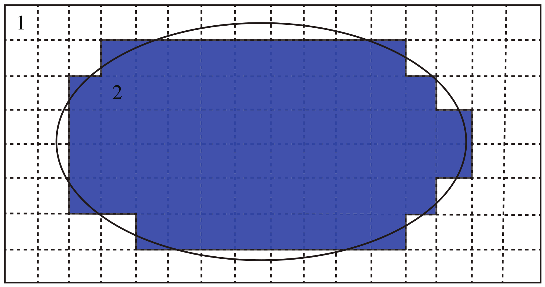
Figure 1. A Cartesian mesh example in a two-dimension plane.
Applsci 10 00058 g001
Figure 2. Cartesian mesh generation baseline, (a) computational domain; (b) a ray passing through the computational domain; (c) result of mesh generation.
Applsci 10 00058 g002
Figure 3. Cartesian mesh lines distribution and ray generation based on ray casting method.
Applsci 10 00058 g003
Figure 4. Lattice grid method for primitive searching.
Applsci 10 00058 g004
Figure 5. Overlap test between triangle and grid in projection plane ( s x and s y are the cell size in X and Y dimension, respectively).
Applsci 10 00058 g005
Figure 6. Intersection cases between ray and triangle in three-dimensional space.
Applsci 10 00058 g006
Figure 7. Flowchart of Cartesian mesh generation algorithm based on the graphics processing unit (GPU) parallel ray casting method.
Applsci 10 00058 g007
Figure 8. Cartesian mesh generation result of a simplified Hubble Space Telescope model, (a) Hubble Space Telescope model; (b) projection result from one perspective; (c) result of mesh generation.
Applsci 10 00058 g008
Figure 9. Result of Cartesian mesh generation for computational domain containing a large number of geometries, (a) an aircraft model; (b) mesh generation result of the aircraft engine; (c) mesh generation result of the aircraft wheel.
Applsci 10 00058 g009
Figure 10. A house model for performance test.
Applsci 10 00058 g010
Figure 11. A model containing 64 spheres for performance test.
Applsci 10 00058 g011
Figure 12. Time percentage of parallel algorithm executing in GPU.
Applsci 10 00058 g012
Figure 13. Average occupancy of parallel algorithm executing in GPU.
Applsci 10 00058 g013
Figure 14. Total running time of mesh generation using two algorithms with different number of cells (the red line and symbols represent the total running time of traditional serial algorithm, and the blue line and symbols represent the total running time of parallel algorithm).
Applsci 10 00058 g014
Figure 15. Total running time of mesh generation using two algorithms with different number of facets (the red line and symbols represent the total running time of traditional serial algorithm, and the blue line and symbols represent the total running time of parallel algorithm.)
Applsci 10 00058 g015
Table 1. Mesh generation time comparison between the sequential and parallel algorithm.
ModelsModel 1Model 2Model 3Model 4
Facet number 1.9 × 10 4 1.3 × 10 5 4.5 × 10 4 9.5 × 10 4
Mesh cells number 9.6 × 10 9 2.4 × 10 11 1.2 × 10 9 4.1 × 10 9
Traditional serial algorithmMesh line generation (s)0.367.900.210.26
Property mapping (s) 5.2 × 10 2 1.7 × 10 4 1.2 × 10 2 8.9 × 10 2
Total time (s) 5.2 × 10 2 1.7 × 10 4 1.2 × 10 2 8.9 × 10 2
GPU parallel algorithmTotal time (s)35.37 1.13 × 10 3 8.4561.23
Speed-up ratio14.315.314.414.6