Article

Numerical Evaluation of Rotordynamic Coefficients for Compliant Foil Gas Seal

1
Faculty of Mechanical and Electrical Engineering, Kunming University of Science and Technology (KUST), Kunming CN-650500, China
2
Department of Mechanical Engineering, Blekinge Institute of Technology, SE-37179 Karlskrona, Sweden
3
Industrial Ecology Programme, Department of Energy and Process Engineering, Norwegian University of Science and Technology, N-7491 Trondheim, Norway
*
Author to whom correspondence should be addressed.
Appl. Sci. 2020, 10(11), 3828; https://doi.org/10.3390/app10113828
Submission received: 23 April 2020 / Revised: 19 May 2020 / Accepted: 26 May 2020 / Published: 31 May 2020
(This article belongs to the Section Applied Industrial Technologies)

Abstract

:

Featured Application

Compliant foil gas seal is an advanced cylindrical gas seal technology and can be commonly used in the secondary flow system of aero-engine, natural gas compressor, and other turbine machineries.

Abstract

Compliant foil gas seal is one of the advanced cylindrical gas seal technologies and can be commonly used in the secondary flow system of an aero-engine. It can enhance the dynamic stability of the aero-engine by meeting the steady requirements of the aero-engine seal system. To evaluate the performance of compliant foil gas seal, the steady performance of the gas seal is firstly analyzed to predict the sealing efficiency and obtain the pressure distribution of the gas seal in the compressible flow field. Then, the effects of the operating parameters on the rotordynamic coefficients are analyzed using the finite differential method. It can be used to predict the operation performance of the aero-engine and prepare for the optimization and test rig of compliant foil gas seal on the T-shaped groove.

1. Introduction

The deformation generated by heat and vibration in the small seal gaps may lead to seal system instability and failure [1,2]. To resolve the challenges and increase the control efficiency of the power system response, the cylindrical structure of the gas seal was designed to avoid seal system failure and improve efficiency with its compliant structure [3,4]. Compliant foil gas seal was one of the advanced cylindrical gas seals and first introduced by Mohsen and Heshmat [5]. It can be used to reduce leakage in extremely small gaps of the secondary flow system of the areo-engine, including in compressors, turbine, and even other turbomachinery [6,7]. The compliant foil gas seal can increase the seal efficiency and reliability of the aero-engine, and its main role is flexible ability in dynamic deformation [6]. Therefore, the numerical evaluation of the compliant foil gas seal is analyzed in this paper, and it is beneficial to predict the performance of the compliant foil gas seal in a complex environment by meeting the steady requirements of the gas seal. At the same time, the numerical evaluation also acquires the optimization values of operating parameters and reduces the costs of the test rig [8]. To investigate the numerical performance of the gas seal, the Reynolds lubrication equation and Hirs lubricate equation was commonly used to solve the flow model in the related researches [9]. Nordmann and Dietzen [10] derived a finite difference procedure to solve the dynamic coefficients of the seal at an eccentric position with a turbulent model. Ha [11,12] evaluated the leakage of different seals to acquire the prediction using commercial computational fluid dynamics (CFD) software. Su [13] analyzed the numerical performance of a cylinder gas seal on the T-shaped groove using CFD software. With the uncertainty of CFD software analyses in the field of gas seal, Ma [14,15] developed the finite element method (FEM) to analyze the quasi-dynamic characteristics of a cylindrical gas seal based on high dynamic performance of the fluid lubrication bearing and numerical evaluation of rotordynamic coefficients of the spiral groove. Lu [16] used the finite difference method (FDM) to acquire the numerical performance of the cylindrical gas seal on the slot and spiral groove. Because of high accuracy and short computation time, this study used the FDM to extend the analysis of the cylindrical gas seal presented by Lu [16] and determine the rotordynamic coefficients of the compliant foil gas seal on the T-shaped groove. In this paper, the steady performance of the compressible flow field of the compliant foil gas seal was calculated using the different operating parameters, and pressure distribution was obtained to verify the credibility of the numerical analysis. The rotordynamic coefficients were integrated by the gas force in the seal area in this study, including stiffness and damping coefficients. The stiffness K and damping D are important rotordynamic coefficients that provide the stability and instability of the seal system [17,18].

2. Methods

Figure 1 illustrates the geometry of a compliant foil gas seal. This study assumes that the linearity of the stiffness of spring bump foil is independent on bump deflection. The effect of the top foil compliance is ignored. The laminar flow model is obtained by calculating the Reynolds number in this paper.

2.1. Governing Equation

The relevant non-dimensional Reynolds equation for the compressible flow of the cylindrical gas seal can be presented as Equation (1):
θ ( p ¯ h 3 ¯ p ¯ θ ) + R 2 L 2 z ¯ ( p ¯ h 3 ¯ p ¯ z ¯ ) = Λ θ ( p ¯ h ¯ )
where z ¯ , p ¯ , h ¯ , Λ , and θ are, respectively, the dimensionless axis distance from inlet to the outlet, pressure, gas thickness, compressible number, and circumferential angle with the following dimensionless variables, given by Equation (2):
z ¯ = Z / R , p ¯ = p / p a ,   h ¯ = h / C , Λ = 6 μ ω R 2 / ( C 2 p a )  
where L, R, C, Z, and h are, respectively, the seal length, rotor radius, mean gas thickness, axial length, and gas thickness. Moreover, ω is the rotor speed, μ is the gas viscosity. p a the is standard pressure, and p is the operation pressure.   ε is the eccentric ratio. As given by Equation (3), the gas forces of F x and F y are integrated by the dynamic pressure along the X and Y radial directions of the seal [5].   F x and F y are the gas force in the X and Y directions
F y , x = L / 2 L / 2 0 2 π ( p p a ) { c o s θ s i n θ } R d θ d z

2.2. Rotordynamic Coefficient Approach

Stiffness and damping coefficients for the compliant foil gas seal are obtained by extending the MATLAB code developed by Lu [16]. The evaluation of rotordynamic coefficients can be used in the rotordynamic analysis of the system with assuring leakage and the system stability over the range of the operating conditions. The effect of temperature on the stiffness values were not compensated by the variety of the gas friction on the gas property. The direct stiffness ( K x x , K y y ) and direct damping ( D x x , D y y ) are important coefficients for the stability of the seal system. Cross-coupled stiffness ( K x y , K y x ) and cross-coupled damping ( D x y , D y x ) are related to the instability of seal system, which can be determined by Equations (4) and (5) [16],
[ K x x K x y K y x K y y ] = R L p C 0 1 0 2 π [ p x ¯ cos θ p y ¯ cos θ p x ¯ sin θ p y ¯ sin θ ] d θ d z ¯   ( 2.2 . 1 )
[ D x x D x y D y x D y y ] = R L p μ C 0 1 0 2 π [ p x ¯ cos θ p y ¯ cos θ p x ¯ sin θ p y ¯ sin θ ] d θ d z ¯   ( 2.2 . 2 )

3. Results

3.1. Numerical Analysis for Reliability

Ma [14] developed FEM to analyze the performance of the spiral cylinder gas seal based on the Reynolds lubrication theory. The pressure distribution of the gas seal is obtained for testing case validation in this paper, and the comparison of pressured results is shown in Figure 2. The number of nodes and elements for FDM this research used is based on Lu’s paper, which is approximately 16,000. The inlet pressure is 301,325 MPa, and the speed is 10,000 rpm. The operation condition adjusts according to the boundary condition [19]. This paper used the central difference method of FDM to solve the pressure distribution rotordynamic coefficients. Figure 2a shows the non-dimensional film thickness of the gas film. Figure 2b,c illustrates the results of the circumferential direction pressure distribution with five different non-dimensional length positions at the T-shaped groove area and smoothing area of the seal (axial direction z ¯   0.21, 0.42, 0.53, 0.64, and 0.85). As the approximate Λ = 27, the position z ¯   1 is far from the groove area, which is similar to the smoothing structure of Cheng [9], and the pressure distribution of the other areas is almost the same. Therefore, the results were validated. However, Figure 2c shows that the pressure of z ¯   0.21, 0.42, and 0.53 decreases abruptly in the near thinnest position, which results from the impact of the groove on the pressure. Furthermore, Figure 2 also shows that the peak pressure is clearly higher than the smoothing area due to the influence of the T-shaped groove. The rise of pressure is beneficial to improve the rotordynamic coefficients.

3.2. Rotordynamic Coefficients with Eccentricity Ratio

Considering the initial condition, the equations of leakage, gas force, and rotordynamic coefficients are numerically solved. The parameters for a typical turbine used in calculations are given in Table 1.
The FDM is employed to solve the obtained equation. In this section, 2D FDM analysis of the compliant foil gas seal for different operating conditions is conducted. The steady performance of the eccentric ratios is shown in Figure 3. It is still extremely significant to analyze the steady results of the leakage, gas force, eccentric angle, and friction because these results are the basic performance of the gas seal, and they can be guaranteed to study the stiffness and damping coefficients of the compliant foil gas seal.
Figure 3a shows that leakage and gas force increases with the rise of eccentric ratio at approximately 10,000 rpm. The leakage changes at approximately 36.7%, and the gas force increases at approximately 83%, but the amplitude of the leakage is still relatively smaller than that of other seals, so the larger eccentric ratio can be selected without the influence of the dynamic factor. As a result, the larger eccentric ratio can be adjusted in the same conditions, including groove and operation parameters. The trend can be nearly discussed by Equations (6)–(10) [20,21,22]:
d Q = C 3 ( 1 + ε cos θ ) 3 12 μ p x R d θ ± U 2 C ( 1 + ε cos θ ) .
The integral results are obtained by the short bearing approximation, and p / x is neglected as presented in Equation (7):
Q = U L C ε .
Q is the leakage, and U represents the mean velocity. The symbols ‘+’ and ‘−’ indicate the velocity direction. The gas flows from the high area to the lower area, which leads the leakage flow away, and the mean velocity is positive. Therefore, the leakage will increase gradually with the eccentric ratios increasing. The gas force, which is concluded by Equation (8), increases gradually and is consistent with the regular short-bearing approximation. This is helpful to improve the rotordynamic coefficients.
F = μ U L 3 ε ( π 2 ( 1 ε 2 ) + 16 ε 2 ) 1 2 / [ 4 c 2 ( 1 ε 2 ) 2 ]
Figure 3b shows the attitude angle β , and friction Ff changes with the increase of eccentric ratios for speed of 10,000 rpm. The attitude angle   β decreases at approximately 55.6% as eccentric ratios increase, which is beneficial to rotordynamic stability. Friction increases at approximately 77% with increasing eccentric ratios. These are almost verified by Equations (9) and (10) of short-bearing approximations:
β = tan 1 [ π ( 1 ε 2 ) 1 / 2 / 4 ε ]
F f = μ U L R π ( 1 + ( 1 + ε ) ) 1 / 2 / C ( 1 ε 2 ) 1 / 2
As can be obtained in Figure 4, the impact of eccentric ratio on the rotordynamic coefficients can be seen clearly from 0.6. The dynamic coefficients are relatively insensitive to changes in eccentric ratio when the eccentricity ratio is smaller than 0.5. The absolute value of direct stiffness K x x and K y y shows almost the same trend, which arrives at a peak value as the eccentricity ratio is approximately 0.7. Similarly, the change of cross-coupled stiffness shows the same results. However, the amplitude of cross-coupled stiffness and damping abruptly increases as the eccentricity ratio is higher than 0.7. This damages the stability of the rotor system, so it is necessary for the good performance of the aero-engine to adjust the eccentric ratio to approximately 0.7.

3.3. Rotordynamic Coefficients with Inlet Pressure

The inlet pressure ranges from 0.1 to 0.5 MPa as the value of the outlet pressure is always 0.1 MPa. According to the graphs illustrated in Figure 5, the leakage increases at approximately 88.3%, and gas force increases at 63.7% with the pressure ratio growing from 1 to 5. Beta and friction also increase at 61% and 15.1%, respectively. This shows that increasing pressure ratio is not beneficial to the steady performance. The multi-stage gas seal can be considered.
As illustrated in Figure 6, the direct stiffness and direct damping are still indicated in the same tendency, and the peak presents a rising trend with the increase in pressure ratio. Furthermore, the cross-coupled stiffness and cross-coupled damping are almost symmetrical around a special value or a linearity equation, and the amplitude gradually decreases with increasing pressure ratio. These variants of rotordynamic coefficients show that the compliant foil gas seal can be applied in high-pressure ratio conditions of the aero-turbine by guaranteeing a steady performance.

3.4. Rotordynamic Coefficients with Speed

As can be seen in Figure 7a, the leakage drops at 0.5% and climbs slowly, but the variation of leakage is extremely minor, and the gas force increases at 19.6%, with the inlet pressure growing from 6000 rpm to 16,000 rpm. Simultaneously, the attitude angle   β decreases at 55.6%, and the friction rises at approximately 62.5%.
As Figure 8 shows, the direct stiffness and direct damping still show a similar change and reach a peak at approximately 12,000 rpm. In addition, the cross-coupled stiffness is almost symmetrical, as well. The amplitude of the cross-coupled damping tends to the zero in limited conditions. The results need to be optimized further.

4. Conclusions

To obtain a high-performance aero-engine, the numerical evaluation of the gas seal was studied to improve the efficiency in many studies. However, many numerical analyses of rotordynamic coefficients for gas seals have been used in face gas seal, smoothing, and spiral cylindrical gas seals for aero-engines, including CFD analysis. This study analyzes the T-shaped groove of the compliant gas seal, and the steady performance of the compliant foil gas seal on the operating parameters is obtained by FDM. Subsequently, the steady analysis can be extended to evaluate rotordynamic coefficients of the compliant foil gas seal. These conclusions are mentioned in this study as follows:
(1)
For leakage and gas force evaluation of the compliant foil gas seal, the inlet pressure has the largest influence on the performance of the compliant foil gas seal. For the amplitude angle and friction, the impact of eccentricity ratio is greater than other factors. It is clear that speed is relatively small for the sealing system.
(2)
Regarding the direct stiffness coefficient and direct damping evaluation, the analysis results show the same tendency as the operation parameters change. The peak values of the direct coefficients increase with the growth of the eccentric ratio. However, the peak values of the direct coefficients decrease with the growth of pressure ratio and speed, which is harmful to the stability of the rotor system, so the initial operating values should be paid more attention when the parameters of the T-shaped groove need to be optimized further.
(3)
Regarding the cross-coupled stiffness and cross-coupled damping coefficient evaluation, the results show that they are almost symmetrical about the special value. Furthermore, they reach the peak point with the same value of the eccentric ratio, speed, and inlet pressure.
(4)
For the rotordynamic coefficient evaluation, it is necessary for plotting the prediction curve to obtain more parameters and coefficients in the future.

Author Contributions

Conceptualization, X.W. and M.L.; methodology, X.W.; software, X.W.; validation, X.W.; formal analysis, X.W.; investigation, X.W.; resources, X.W. and M.L.; data curation, X.W.; writing—original draft preparation, X.W.; writing—review and editing, X.W., S.K.-W., and X.H.; project administration, M.L.; funding acquisition, S.K.-W. All authors have read and agreed to the published version of the manuscript.

Funding

This research was funded by the China Scholarship Council (grant no. 201708740009).

Acknowledgments

The current research has been supported by the China Scholarship Council (grant no. 201708740009).

Conflicts of Interest

We declare no conflict of interest. The funders had no role in the design of the study; in the collection, analyses, or interpretation of data; in the writing of the manuscript, or in the decision to publish the results.

References

  1. Sayma, A.I.; Breard, C.; Vahdati, M.; Imregun, M. Aeroelasticity Analysis of Air-riding seals for Aero-engine Applications. J. Tribol. 2002, 124, 607–616. [Google Scholar] [CrossRef]
  2. Xu, J.; Peng, X.D.; Bai, S.X.; Meng, X.K.; Li, J.Y. Experiment on wear behaviour of high pressure gas seal faces. Chin. J. Mech. Eng. 2014, 27, 1287–1293. [Google Scholar] [CrossRef]
  3. Wilbur, S.; Antonio, A. Numerical, Analytical, Experimental Study of Fluid Dynamic Forces in Seals; NASA Center for Aerospace Information: Hanover, MA, USA, 2004; Volume 2, pp. 1–140.
  4. Wilbur, S.; Antonio, A. Numerical, Analytical, Experimental Study of Fluid Dynamic Forces in Seals Interim; Report No. 1; Lewis Research Center of American: Cleveland, OH, USA, 1992. [Google Scholar]
  5. Mohsen, S.; Hooshang, H. On the Fluid Flow and Thermal Analysis of a Compliant Surface Foil Bearing and Seal. Tribol. Trans. 2000, 43, 318–324. [Google Scholar]
  6. Hendricks, R.C.; Steinetz, B.M.; Athavale, M.M.; Przekwas, A.J.; Braun, M.J.; Dozozo, F.K.; Kudriavtsev, V.V.; Mullen, R.L.; Von Pragenau, G.L. Interactive development of seals, bearings, and secondary flow systems with the power stream. Int. J. Rotating Mach. 1995, 1, 153–185. [Google Scholar] [CrossRef] [Green Version]
  7. Bruce, M.S.; Robert, C.H. Engine Seal Technology Requirements to Meet NASA’s Subsonic Technology Program Goals. J. Propuls. Power 1996, 12, 786–793. [Google Scholar]
  8. Liu, Y.C. Behavior of Gas Film Face Seal. Ph.D. Thesis, Beijing University of Aeronautics and Astronautics, Beijing, China, 1999. [Google Scholar]
  9. Hirs, G. A bulk-flow theory for turbulence in lubricant films. ASME J. Lubr. Technol. 1973, 105, 137–146. [Google Scholar] [CrossRef]
  10. Nordmann, R.; Dietzen, F. Finite Difference Analysis of Rotordynamic Seal Coefficients for an Eccentric Ratios Shaft Position; N89-22906; Department of Mechanical Engineering University of Kaiserslautern: Kaiserslautern, Germany, 1989. [Google Scholar]
  11. Ha, T.W. Prediction of combination-type-staggered labyrinth seal leakage using CFD. J. KSTLE 2006, 22, 66–72. [Google Scholar]
  12. Ha, T.W. Prediction of non-contact-type seal leakage using CFD. J. Fluid Mach. 2006, 9, 14–21. [Google Scholar]
  13. Su, Z.H. Numerical Simulation and Performance Analysis of Cylinder Gas Film Seal. Master’s Thesis, Kunming University of Science and Technology, Kunming, China, 2016. [Google Scholar]
  14. Ma, G.; Xi, P. Analysis of quasi-dynamic characteristics of compliant floating ring gas cylinder seal. J. Aerosp. Power 2010, 25, 1190–1196. [Google Scholar]
  15. Ma, G.; Xu, G.Z.; Shen, X.M. Design and Analysis for Spiral Grooved Cylindrical Gas Seal Structural Parameter. Lubr. Eng. 2007, 32, 127–130. [Google Scholar]
  16. Lu, J.J. Study on Dynamic Lubrication Characteristics of a New Floating Cylindrical Groove Gas Film Seal. Ph.D. Thesis, Lanzhou University of Technology, Lanzhou, China, 2018. [Google Scholar]
  17. Salehi, M.; Heshmat, H. Performance of a Complaint Foil Seals in a Small Gas Turbine Engine Simulator Employing A Hybrid Foil/Ball Bearing Support System. Tribol. Trans. 2001, 44, 458–464. [Google Scholar] [CrossRef]
  18. Tae, W.H.; Bok, S.C. Numerical prediction of rotordynamic coefficients for an annular-type plain-gas seal using 3D CFD analysis. J. Mech. Sci. Technol. 2014, 28, 505–511. [Google Scholar]
  19. Noel, B.; Bernard, T.; Jean, F. Influence of Fluid Flow Regime on Performances of Non-Contacting Liquid Face Seals. J. Tribol. 2002, 124, 515–523. [Google Scholar]
  20. Shen, X.M.; Liu, Y.C.; Ma, G. Tribology for Aero-Gas Turbine Engines; Beijing University of Aeronautics; Astronautics Press: Beijing, China, 2008; pp. 23–52. [Google Scholar]
  21. George, B.D.; Fred, W.O. Analytical Derivation and Experimental Evaluation of Short-Bearing Approximation for Full Journal Bearings; Report 1157; Cornell University: Ithaca, NY, USA, 1953. [Google Scholar]
  22. Childs, D.W. Finite-Length Solutions for Rotordynamic Coefficients of Turbulent Annular Seals. J. Technol. 1982, 105, 82–142. [Google Scholar] [CrossRef]
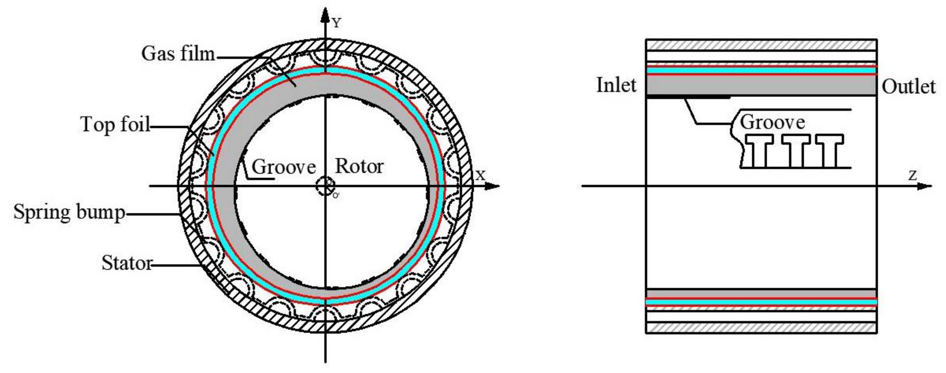
Figure 1. Schematic of the compliant foil gas seal.
Applsci 10 03828 g001
Figure 2. (a) Description of non-dimensional gas thickness with non-dimensional length. (b) Description of non-dimensional pressure with nondimensional length. (c) Comparison of pressure calculated results.
Applsci 10 03828 g002
Figure 3. (a) Description of leakage and force with eccentric ratio. (b) Description of attitude angle and friction with eccentric ratio.
Applsci 10 03828 g003
Figure 4. (a) Description of stiffness coefficient with eccentric ratio. (b) Description of damping coefficient with eccentric ratio.
Applsci 10 03828 g004
Figure 5. (a) Description of leakage and force with pressure ratio. (b) Description of attitude angle and friction with pressure ratio.
Applsci 10 03828 g005
Figure 6. (a) Description of stiffness coefficient with pressure. (b) Description of damping coefficient with pressure.
Applsci 10 03828 g006
Figure 7. (a) Description of leakage and force with speed. (b) Description of attitude angle and friction with speed.
Applsci 10 03828 g007
Figure 8. (a) Description of stiffness coefficient with speed. (b) Description of damping coefficient with speed.
Applsci 10 03828 g008
Table 1. The analysis layout of the gas seal [14,16].
ParametersValues
R(mm)25
C (mm)0.005
N 16
Gas mediumair
The ratio of groove0.6
Outlet pressure (Pa)101,325