Article

Novel Fault Injection Attack without Artificial Trigger

Department of Financial Information Security, Kookmin University, 77 Jeongneung-ro, Seongbuk-gu, Seoul 02707, Korea
*
Author to whom correspondence should be addressed.
These authors contributed equally to this work.
Appl. Sci. 2020, 10(11), 3849; https://doi.org/10.3390/app10113849
Submission received: 29 April 2020 / Revised: 25 May 2020 / Accepted: 28 May 2020 / Published: 1 June 2020
(This article belongs to the Special Issue Side Channel Attacks and Countermeasures)

Abstract

:
Theoretical process of fault injection attacks is defined as a process of recovering a secret key assuming that an attacker can inject faults into a specific targeted operation. Therefore, an artificial triggering is required to execute such an attack. However, when conducting analysis on real devices, artificial triggering needs to rely on a powerful assumption, such as manipulation of internal codes. In this paper, we propose a novel fault injection system using Input/Output (I/O) signals of target devices as a trigger for relaxing an attacker assumption. This system does not require an implementation of artificial triggering as input signals are used as a trigger in transmission of plaintexts for fault injection attacks. As a result, the attacker can perform fault injection attacks concerning the entire encryption process. To decide the fault injection time based on the trigger, the proposed system applies simple power analysis (SPA), employing electromagnetic emission of target devices. Considering that the fault injection time identified by SPA can be relatively vague compared with that obtained using a system based on an artificial triggering, we address this problem by proposing a process to recover the secret key without knowing the byte index of an injected fault.

1. Introduction

In 1996, P. Kocher demonstrated that confidential information could be stolen through various physical signals, such as operation time, power consumption, or electromagnetic(EM) emission, occurring when cryptographic algorithms proved to be a mathematically secure were processed on a real device [1]. A side-channel attack is defined as an analytical method to obtain confidential information using the side data from a real device. Boneh et al. proposed the concept of a fault injection attack, corresponding to side-channel attack methods, in 1997 [2]. Fault injection attacks imply injecting artificial faults to induce malfunctions in a device on which a specific algorithm is operated and using the resulting incorrect output to steal the confidential information. Differential fault analysis (DFA) is a method to reveal the confidential information using the difference characteristics and differential between the normal ciphertext and the one obtained as a result of injecting a fault. Existing injection attack methods for the advanced encryption standard (AES) relied on various attacker assumptions. Dusart et al. proposed a DFA method for AES considering an attacker‘s assumption that a fault was injected into the input byte of the MixColumns function in the 9th round of AES [3]. The above AES DFA method is called the PGO (Pierre Dusart, Gilles Letourneus, and Olivier Vivolo who are authors of the paper) DFA method. Then, Chen C.N. and Yen S.M. proposed a DFA method of AES implying injecting a fault into one arbitrary byte of the key scheduling process, which was considered as an attacker‘s assumption [4]. In addition, several research works were focused on using a bit stuck model or a bit-flip model [5,6]. However, all these attacker‘s assumptions were deemed unrealistic concerning real devices.
Fault injection attack systems usually utilize artificial and unnatural triggering to easily obtain fault-injected ciphertexts which are then used in DFA. The attacker needs to revise the code incorporated into the target device to generate an artificial trigger. If a target device is a complete product, revising its code is not suitable for actual scenarios.
Our Contributions. In this paper, we propose a novel fault injection attack system that can be used to ease an attacker‘s assumption for triggering. This system implies utilizing an existing I/O signal as a trigger instead of generating an artificial one. However, it is a difficult task for the attacker to detect the time of a specific operation. To overcome this disadvantage, the proposed system collects an emission electromagnetic trace of a target device and analyzes it to identify the operating time of a specific algorithm. Evidently, the accuracy of such a detection approach is lower compared with that of artificial triggering. The proposed system is not capable of identifying precisely which byte is affected by a fault, while the conventional system can derive this information. To apply the proposed system for snatching confidential information, it is necessary to develop a differential fault analysis method without the premise of the index of byte in which a fault is injected is decided. In this study, we additionally develop a DFA method that can be used to reveal the secret key of the AES encryption algorithm even in the cases when the attacker does not know which bytes have been affected by an injected fault. Moreover, we demonstrate the applicability of the proposed system by conducting the secret key using Arduino UNO board [7].
Related Works. Recently, theoretical DFA methods on various cryptographic algorithms have been studied. In 2012, Lee et al. proposed a DFA method on the HIGHT block cipher [8], which assumes that it is possible for an attacker to inject a random byte fault in the input of the 28th round [9]. A DFA method on ARIA block cipher [10] was suggested by Lee et al. in 2013 [11]. An attacker who uses this method to reveal the master key needs to inject some faults in the input of the last round of encryption and decryption. Jap et al. proposed a DFA method on LEA block cipher [12], which uses a single-bit fault model [13]. DFA methods on SIMON and SPECK block cipher [14] were suggested by H Tupsamudre et al. [15]. A DFA method proposed by Kwon et al. on CHAM-128/128 cipher [16] can extract the master key using about 24 correct–faulty ciphertext pairs as a simulation result [17]. Only studies such as the above DFA papers have simulational experiment results. This means these DFA methods use the assumption that a trigger is set up to inject faults at the desired operations. Moreover, it does not guarantee that these can be applied to actual devices.
Organization. The rest of paper is organized as follows. Section 2 provides a short overview on the electromagnetic fault injection attacks and explains the DFA method of AES implemented by Dusart. In Section 3, we describe the proposed novel fault injection attack system to relax a fault injection attacker‘s assumption about triggering. By experimenting with the Arduino UNO board, we demonstrate the effectiveness of the proposed system, as outlined in Section 4. Finally, Section 5 concludes the paper.

2. Background

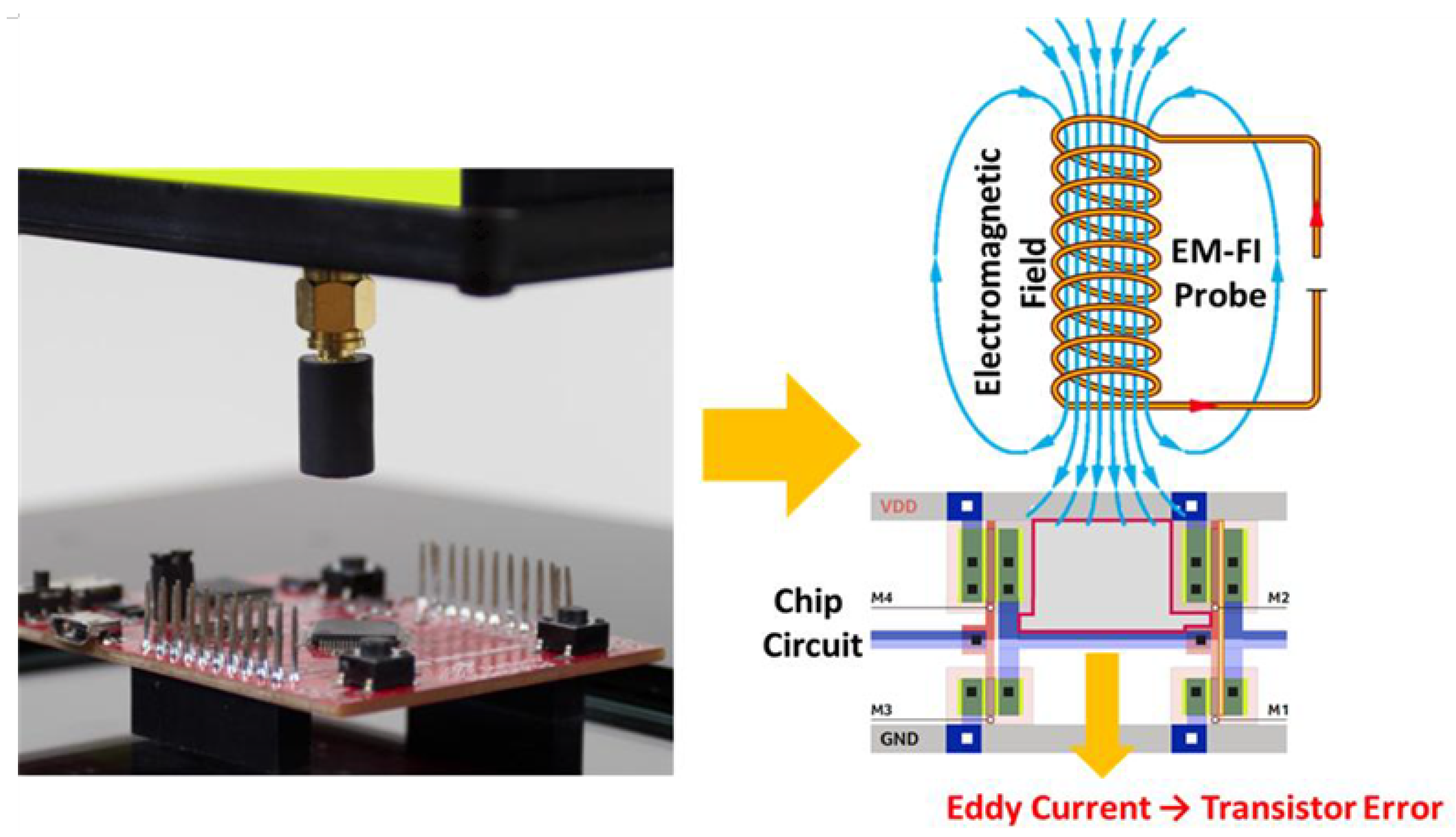
2.1. Electromagnetic Fault Injection Attack

Laser fault injection attacks essentially require performing decapsulation of a target chip, as it is based on the property that semiconductors are sensitive to light. As a hardware countermeasure against laser fault injection attacks, establishing a decapsulation prevention shield has been proposed [18]. Electromagnetic fault injection attacks do not require the decapsulation because a fault caused by electromagnetism can affect semiconductors through integrated circuit packages. Therefore, electromagnetic fault injection attacks can circumvent the hardware countermeasures against laser fault injection attacks. Moreover, electromagnetic fault injection attacks can have similar effects on chips as the ones based on the other fault sources. For example, they can cause logic timing violation and change the current state of a transistor to induce temporary malfunctions on a device, similarly to the clock glitch injection attack.
Figure 1 represents the main principle of electromagnetic fault injection attacks. To generate electromagnetic induction, electromagnetic fault injection attacks cause an instantaneous current to flow through an electromagnetic probe tip implemented by winding ferrite with a coil. As a result, an electromagnetic field is instantaneously generated around the probe tip. Due to the generated electromagnetic field, an eddy current is induced in the chip and affects the inner transistor. Consequently, a malfunction occurs in a circuit. Falsification of the memory data, omission of instructions, or omission of function calls can be generated as a result of this malfunction.

2.2. PGO DFA Method

Dusart et al. performed their formulated DFA on AES [3] so that one byte was affected by a fault between last MixColumns and penultimate MixColumns due to the fault spreading across exactly four bytes of a ciphertext. Figure 2 represents a propagation process of the fault induced into the first byte of the 9th round of SubBytes. Here, what K i , j means is the j-th byte round key of the i-th round of AES. At the first of a ciphertext, we formulate the equations for the normal and faulty cases as follows:
S ( 2 A 3 B C D K 9 , 1 ) K 10 , 1 = O 1 ,
S ( 2 X 3 B C D K 9 , 1 ) K 10 , 1 = O 1 .
By computing XOR equation between Equations (1) and (2), K 11 , 1 is neutralized, and the resulting U 1 can be expressed as follows:
S ( 2 A 3 B C D K 9 , 1 ) S ( 2 X 3 B C D K 9 , 1 ) = O 1 O 1 = U 1 .
Equation (3) can be rewritten as Equation (4):
S ( Y 0 ) S ( 2 Z Y 0 ) = U 1 ( Z = A X , Y 0 = 2 A 3 B C D K 9 , 1 ) .
Similarly, equations corresponding to the other bytes affected by the injected fault can be expressed according to Equations (5)–(7) as follows:
S ( Y 1 ) S ( Z Y 1 ) = U 14 ( Z = A X , Y 1 = A 2 B 3 C D K 9 , 2 ) ,
S ( Y 2 ) S ( Z Y 2 ) = U 11 ( Z = A X , Y 2 = A B 2 C 3 D K 9 , 3 ) ,
S ( Y 3 ) S ( 3 Z Y 3 ) = U 8 ( Z = A X , Y 3 = 3 A B C 2 D K 9 , 4 ) .
Then, we find ( Y 0 , Z ) pair that satisfies Equation (4) corresponding to the known fixed value U 1 . As SubBytes is a nonlinear function, the Z range of guessing the values can be declined repeatedly by using formulas for ( Y 1 , Z ) , ( Y 2 , Z ) , and ( Y 3 , Z ) pairs. Only several values of Z can simultaneously satisfy Equation (4), then Y 0 , Y 1 , Y 2 , and Y 3 guessed values corresponding to the Z range can be reduced. The step is repeated using the other fault-injected ciphertext by considering only the narrow Y 0 , Y 1 , Y 2 , and Y 3 values. Then, we conduct this step repeatedly until the Y 0 , Y 1 , Y 2 , and Y 3 values can be recovered. We assume that the other fault is injected at the same location. If we obtain three different fault-injected ciphertexts and the original one, we can recover the accurate Y 0 , Y 1 , Y 2 , and Y 3 values accordingly. By recovering Y 0 , Y 1 , Y 2 , and Y 3 values, K 10 , 1 , K 10 , 14 , K 10 , 11 , and K 10 , 8 can be obtained according to Equation (8):
S ( Y 0 ) K 10 , 1 = O 1 , S ( Y 1 ) K 10 , 14 = O 14 , S ( Y 2 ) K 10 , 11 = O 11 , S ( Y 3 ) K 10 , 8 = O 8 .

3. Novel Fault Injection Attack System for Relaxing the Fault Injection Attacker‘s Assumption

Conventional fault injection attack system requires identifying an artificial trigger by revising the code of a target device to inject a fault into a targeted operation easily. The proposed system employs I/O signals of target devices as a trigger considering more realistic real-life scenarios. There is no need to consider artificial triggering. Section 3.1 proposes the novel fault injection attack system that uses the I/O signal as the trigger. Then, by using the I/O signal as the trigger, we propose the method in order to specify the timing of target operation. Section 3.2 describes how to snatch the confidential information even if an attacker does not know which byte was injected with a fault.

3.1. Fault Injection Attack System Using I/O Signals as Triggers
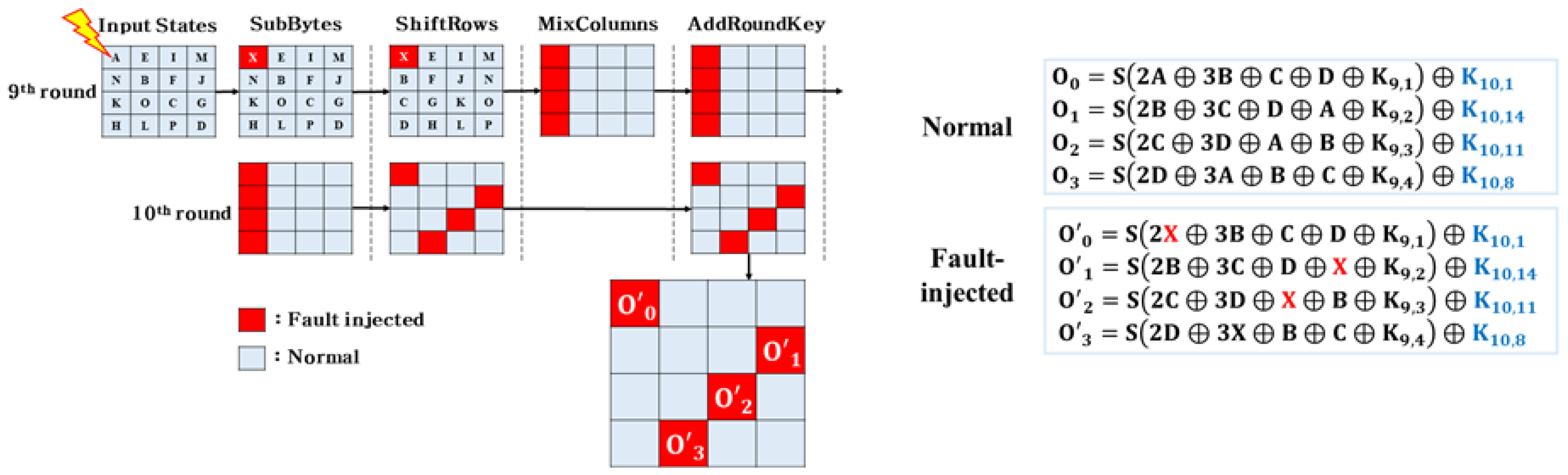
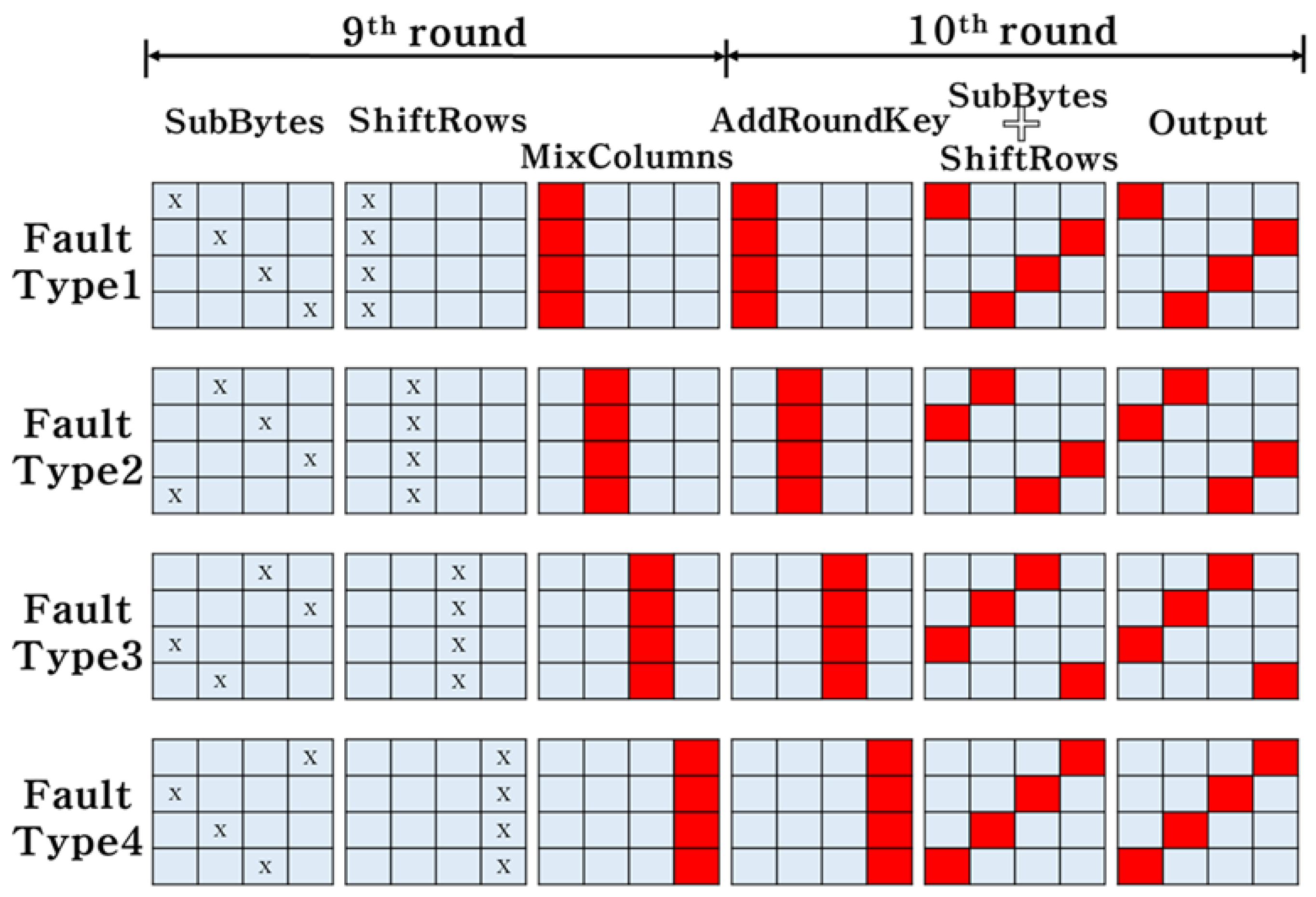
The traditional fault injection attack system requires artificial triggering in order to inject the fault at the attacker‘s desired timing. Artificial trigger setup is possible when the attacker can revise the internal code of the target device. When we analyze the actual device, the attacker‘s assumption is not suitable while revising the mounted code of the target device.
Figure 3 shows a communication process between PC and device. The device conducts the encryption when receiving the plaintext from PC. Then, the device transmits the ciphertext to PC when the encryption is over. The attacker can use the exploiting I/O signals between PC and device as the triggers without the need to set the artificial triggering. If we can use the I/O signals as triggers, the attacker‘s assumption can be relaxed accordingly so that there is no necessity to revise the code incorporated into the target device to establish artificial triggering.
Figure 4 shows the fault injection attack system configuration diagrams. The proposed system includes the oscilloscope, control PC, spider [19], electromagnetic fault injection transient probe [20], and the Arduino UNO board that serves as target device. The proposed system communicates with the control PC and the target device. The oscilloscope is used to register an electromagnetic trace and to accurately detect the location in which a fault has been introduced. Then, the control PC performs an electromagnetic fault injection attack by using Inspector, a side-channel analysis software tool [21]. Inspector can analyze the variety of equipment used for fault injection attacks and save the results of a fault injection attack for further investigation. Moreover, Inspector can be used to check whether fault injection succeeded or failed. An electromagnetic fault injection transient probe consists of the XYZ-table, electromagnetic probe station, and an electromagnetic probe tip [22]. The XYZ-table is used to set attack parameters for a specific location of a target chip. A fault injection attack can be repeatedly performed by moving X, Y, and Z axes. It is performed to find a valid point in the chip to focus fault injection attacks on. Spider is used to control the various communication canals between the target device and the control PC. Moreover, spider can execute various functions, such as restarting through Inspector. Figure 4a represents the configuration diagram for the conventional fault injection attack system, and Figure 4b shows that for the proposed fault injection attack system. As shown in Figure 4, the conventional fault injection attack system requires an additional connection from Arduino UNO board to spider for trigger, whereas the proposed fault injection attack system utilizes the communication line between the control PC and Arduino UNO board. Shaded lines in Figure 4 are for trigger. Since the proposed fault injection attack system makes the trigger line by jumping the communication line, it minimizes the artificial modification of the target board. Considering that the proposed system uses an existing I/O signal as a trigger, it is difficult to identify the location of a specific operation. Therefore, we develop a method to overcome this issue. As shown in Figure 5, we construct an environment using the electromagnetic probe and the oscilloscope to collect an emission electromagnetic trace, then, we perform SPA to identify the time of a target operation. Concerning the rest of the paper, we focus on the AES algorithm even though the attack method is not tied to this algorithm.

3.2. AES DFA Method

In this study, the existing I/O signals are utilized as trigger, and consequently, it is difficult for an attacker to detect the exact operating time of a specific operation compared with the artificial triggering approach. We address this issue by proposing an attack algorithm to analyze the confidential key information without knowing which byte has been injected by a fault.
We conduct a fault injection attack to find all of the 10th round key bytes. In this case, we apply the key recovering algorithm to derive the secret key without knowing which byte index has been injected by a fault. Figure 6 represents fault propagation flow according to various columns of MixColumns that are effected by a fault. According to the ciphertext affected by the injected fault, we can classify a corresponding Fault Type. Table 1 indicates the formulas that can express according to the input byte of 9th round SubBytes into which a fault is injected. The formulas corresponding to the input bytes induced with a fault have different Z coefficients even if they have the same Fault Type. When the fault injection attack is executed successfully, we can derive the input fault injection column index using only the fault-injected ciphertext. However, we cannot distinguish precisely which byte has been injected. Therefore, we need to conduct the analysis for four cases to identify the correct byte index, as expressed in Table 1. The attack algorithm proposed in this paper is defined as follows.
As mentioned in Section 2.2, AES DFA proposed by Dusart can be used to narrow the Y 0 , Y 1 , Y 2 , and Y 3 guessing values and recovers the Y 0 , Y 1 , Y 2 , and Y 3 accurate values considering the three fault-injected ciphertexts. PGO   DFA (Normal Ciphertext, Faulted Ciphertext, Fault-Injected Byte, Guessing Value) used in lines 4∼9 of Algorithm 1 corresponds to a function defined to narrow the Y 0 , Y 1 , Y 2 , and Y 3 guessing values and to recover the accurate values, as shown above. The parameters of the function have the following meanings:
  • Normal Ciphertext: Normal ciphertext used for analysis;
  • Faulted Ciphertext: Fault-injected ciphertext used for analysis;
  • Fault-Injected Byte: Analysis formulas according to an array with fault-injected input bytes corresponding Fault Type;
  • Guessing Value: the Y 0 , Y 1 , Y 2 , and Y 3 guessing pair to narrow.
Before applying the proposed algorithm, the attacker needs to check the ciphertext bytes affected by the fault. We can define Fault Type as the input of a function obtained by checking bytes. The normal ciphertext without fault injection is denoted in the function as Normal Ciphertext. The fault injection ciphertexts are denoted in the function as Faulted Ciphertext. Fault-Injected Byte cannot accurately derive the information about the input fault byte corresponding to the same Fault Type, as shown in Table 1. We need an array with an index of input fault bytes corresponding to the same Fault Type. Then, the formulas utilized in the analysis are decided according to the Fault-Injected Byte. Guessing Value denotes the Y 0 , Y 1 , Y 2 , and Y 3 pairs that are used to limit the guessing value range. The  10 15 lines of Algorithm 1 describe that the key can be recovered if the Y 0 , Y 1 , Y 2 , and Y 3 value is the only one. If we correctly guess the input byte corresponding to each fault-injected ciphertext, the correct value is obtained. However, if we incorrectly guess the input byte, the correct value cannot be derived. Here,  α 0 , α 1 , α 2 , and α 3 denote the ciphertext bytes index affected by the fault corresponding to Fault Type. Therefore, it is possible to recover the correct four keys as described in 10∼15 lines of Algorithm 1. Similarly, if three fault-injected ciphertexts are considered for each Fault Type, we can identify the 10th round key of 16 bytes. In worst case, our proposed algorithm performs PGO   DFA 84 times. Let the time complexity of PGO   DFA be O ( PGO   DFA ) . Since PGO   DFA performs 2 16 guesses for every four bytes, O ( PGO   DFA ) is O ( 2 18 ) . Therefore, O ( 84 × 2 18 ) guesses is finished in a couple of seconds. In this paper, we demonstrate that the attacker can analyze the confidential key information without knowing which byte index has been injected by a fault using the proposed algorithm.
Algorithm 1 Key recovery algorithm
Input: sequence set of C , C : = ( C [ 0 ] , C [ 1 ] , , C [ 15 ] ) ,
C : Normal ciphertext
C 1 , C 2 , C 3 : Fault-injected ciphertext of the same Fault Type
 Fault Type: Fault Type { 1 , , 4 }
 Fault-Injected Byte: Fault-injected input bytes corresponding Fault Type
       T y p e 1 { 1 , 6 , 11 , 16 } , T y p e 2 { 4 , 5 , 10 , 15 } , T y p e 3 { 3 , 8 , 9 , 14 } , T y p e 4 { 2 , 7 , 12 , 13 }
Y: Possible Guessing Value, Y : = ( Y 0 , Y 1 , Y 2 , Y 3 ) , ( Y i { 0 , 255 } , 0 i 3 )
Output: ( K 0 , K 1 , K 2 , K 3 ) : 4-byte 10th round keys
 1: procedure DFA ( C , C 1 , C 2 , C 3 , Fault Type)
 2: initialize Y to all of guessing values
 3: T Fault Type
 4: for i = 0 to 3 do
 5:  M PGO   DFA ( C , C 1 , T y p e T [ i ] , Y )
 6: for j = 0 to 3 do
 7:   N PGO   DFA ( C , C 2 , T y p e T [ j ] , M )
 8:  for k = 0 to 3 do
 9:    O PGO   DFA ( C , C 3 , T y p e T [ k ] , N )
 10:   if O NULL then
 11:     K 0 S ( Y 0 ) xor C [ α 0 ]
 12:     K 1 S ( Y 1 ) xor C [ α 1 ]
 13:     K 2 S ( Y 2 ) xor C [ α 2 ]
 14:     K 3 S ( Y 3 ) xor C [ α 3 ]
 15:    return ( K 0 , K 1 , K 2 , K 3 )
 16: return FAILED
 17: end procedure

4. Experiment

In this section, we describe the experiment conducted to test the proposed fault injection attack system using I/O signals as triggers. An electromagnetic fault injection attack was performed on the Arduino UNO board of AES.

4.1. Experimental Setup

4.1.1. Specifying the Time of a Fault Injection Attack

As emphasized, the experimental setup constructs Figure 4b system to execute a fault injection attack with relaxing an attacker‘s assumption. We acquired the electromagnetic traces while AES encryption was performed on the Arduino UNO board, as shown in Figure 5. The collected electromagnetic trace is represented in Figure 7. Figure 7a depicts the electromagnetic trace of AES. Figure 7b shows the magnified electromagnetic trace corresponding to 8th, 9th, and 10th rounds in AES considered to identify the time of a target operation. As mentioned in Section 3.2, the location of the specific operation corresponds to the part of the 9th round in SubBytes and ShiftRows, performing the electromagnetic fault injection attack in the range of 655∼675 μ s.

4.1.2. Electromagnetic Fault Injection Attack

Figure 8 represents the experimental environment configuration constructed to conduct an electromagnetic fault injection attack on AES implemented on the Arduino UNO board. The electromagnetic fault injection attack environment included the oscilloscope, Riscure‘s EMFI(Electromagnetic Fault Injection) transient probe, EM(Electromagnetic) probe station, EM probe tips, and the spider. The fault injection attack was conducted by applying the side-channel analysis software Inspector. In this study, a fault was injected randomly in the range of 655∼675 μ s from the start of encryption to identify the 16-byte 10-round key. The location of electromagnetic fault injection on the Arduino UNO board is represented in Figure 8, and the chip area is divided into ten equal parts horizontally and five equal parts vertically. Fault injection was performed 20 times for each point, thereby executing a total of 1000 fault injection attacks.

4.2. Experimental Results

The experimental results are provided in Table 2. The used data correspond to 16-byte ciphertext information. The marked byte as * denotes the byte affected by the fault injection attack. Here, ➀ is the resulting value without the fault being injected; ➁∼➄ correspond to the resulting values of one column in the 9th round MixColumns affected by a fault; ➅∼➇ represent the resulting values when more than two columns are affected. Table 3 represents different fault types from ➀ to ➇. As a result of the experiment, we obtained 15 fault injection ciphertexts of Fault Type1, eight fault injection ciphertexts of Fault Type2, 15 fault injection ciphertexts of Fault Type3, and 17 fault injection ciphertexts of Fault Type4.
In this experiment, a one-byte fault injection attack was executed successfully 55 times out of the 1000 conducted fault injection attacks overall. Three fault injection ciphertexts used for analysis could be obtained for each Fault Type by executing 250 fault injection attacks, on average. As a result, we found the 16-byte 10-round key using the fault-injected ciphertexts using the attack algorithm described in Section 3.2.

5. Conclusions

In present paper, we proposed a system aimed to relax an attacker‘s assumption for triggering. As mentioned in Section 3.1, the attacker‘s assumption could be eased by using the existing I/O signal as a trigger instead of generating an artificial one. To identify the operation time, the specific algorithm was used, which implied registering an emission electromagnetic trace and applying simple power analysis. As we set the entire 9th round of SubBytes and ShiftRows as the target operation, a fault could be injected into each input byte of 9th round of MixColumns. Therefore, various fault-injected ciphertexts could be acquired to generate a 16-byte 10-round key. Moreover, we proposed an algorithm to analyze the generated key without knowing the index of a byte injected by a fault using the fault-injected ciphertexts. The system proposed in this paper can be used to relax an attacker‘s assumption by applying not only the previously tested AES cryptographic algorithm, but also other fault injection attacks.

Author Contributions

These authors contributed equally to this work. All authors have read and agreed to the published version of the manuscript.

Funding

This work was supported by Institute of Information & communications Technology Planning & Evaluation(IITP) grant funded by the Korea government(MSIT) (No.2020-0-00913, Study on Wireless Covert Channel Risk Verification).

Conflicts of Interest

The authors declare no conflict of interest.

References

  1. Kocher, P.C. Timing attacks on implementations of Diffie-Hellman, RSA, DSS, and other systems. In Annual International Cryptology Conference; Springer: Berlin/Heidelberg, Germany, 1996; pp. 104–113. [Google Scholar]
  2. Boneh, D.; DeMillo, R.A.; Lipton, R.J. On the importance of checking cryptographic protocols for faults. In International Conference on the Theory and Applications Of Cryptographic Techniques; Springer: Berlin/Heidelberg, Germany, 1997; pp. 37–51. [Google Scholar]
  3. Dusart, P.; Letourneux, G.; Vivolo, O. Differential fault analysis on AES. In International Conference on Applied Cryptography and Network Security; Springer: Berlin/Heidelberg, Germany, 2003; pp. 293–306. [Google Scholar]
  4. Chen, C.N.; Yen, S.M. Differential fault analysis on AES key schedule and some countermeasures. In Australasian Conference on Information Security and Privacy; Springer: Berlin/Heidelberg, Germany, 2003; pp. 118–129. [Google Scholar]
  5. Blömer, J.; Seifert, J.P. Fault based cryptanalysis of the advanced encryption standard (AES). In International Conference on Financial Cryptography; Springer: Berlin/Heidelberg, Germany, 2003; pp. 162–181. [Google Scholar]
  6. Giraud, C. Dfa on aes. In International Conference on Advanced Encryption Standard; Springer: Berlin/Heidelberg, Germany, 2004; pp. 27–41. [Google Scholar]
  7. Arduino Uno Rev3. Available online: https://store.arduino.cc/usa/arduino-uno-rev3 (accessed on 30 May 2020).
  8. Hong, D.; Sung, J.; Hong, S.; Lim, J.; Lee, S.; Koo, B.S.; Lee, C.; Chang, D.; Lee, J.; Jeong, K.; et al. HIGHT: A new block cipher suitable for low-resource device. In International Workshop on Cryptographic Hardware and Embedded Systems; Springer: Berlin/Heidelberg, Germany, 2006; pp. 46–59. [Google Scholar]
  9. Lee, Y.; Kim, J.; Hong, S. A Differential Fault Attack against Block Cipher HIGHT. J. Korea Inst. Inf. Secur. Cryptol. 2012, 22, 485–494. [Google Scholar]
  10. Kwon, D.; Kim, J.; Park, S.; Sung, S.H.; Sohn, Y.; Song, J.H.; Yeom, Y.; Yoon, E.J.; Lee, S.; Lee, J.; et al. New block cipher: ARIA. In International Conference on Information Security and Cryptology; Springer: Berlin/Heidelberg, Germany, 2003; pp. 432–445. [Google Scholar]
  11. Lee, Y.; Jeong, K.; Sung, J.; Hong, S. Improved Differential Fault Analysis on ARIA using Small Number of Faults. IACR Cryptol. EPrint Arch. 2013, 2013, 191. [Google Scholar]
  12. Hong, D.; Lee, J.K.; Kim, D.C.; Kwon, D.; Ryu, K.H.; Lee, D.G. LEA: A 128-bit block cipher for fast encryption on common processors. In International Workshop on Information Security Applications; Springer: Berlin/Heidelberg, Germany, 2013; pp. 3–27. [Google Scholar]
  13. Jap, D.; Breier, J. Differential fault attack on LEA. In Information and Communication Technology-EurAsia Conference; Springer: Berlin/Heidelberg, Germany, 2015; pp. 265–274. [Google Scholar]
  14. Beaulieu, R.; Shors, D.; Smith, J.; Treatman-Clark, S.; Weeks, B.; Wingers, L. The SIMON and SPECK Families of Lightweight Block Ciphers. IACR Cryptol. EPrint Arch. 2013, 2013, 404–449. [Google Scholar]
  15. Tupsamudre, H.; Bisht, S.; Mukhopadhyay, D. Differential fault analysis on the families of SIMON and SPECK ciphers. In Proceedings of the 2014 Workshop on Fault Diagnosis and Tolerance in Cryptography, Busan, Korea, 23 September 2014; IEEE: Piscataway, NJ, USA, 2014; pp. 40–48. [Google Scholar]
  16. Koo, B.; Roh, D.; Kim, H.; Jung, Y.; Lee, D.G.; Kwon, D. CHAM: A family of lightweight block ciphers for resource-constrained devices. In International Conference on Information Security and Cryptology; Springer: Berlin/Heidelberg, Germany, 2017; pp. 3–25. [Google Scholar]
  17. Kwon, H.; Ha, J. Fault Injection Attack on Lightweight Block Cipher CHAM. J. Korea Inst. Inf. Secur. Cryptol. 2018, 28, 1071–1078. [Google Scholar]
  18. Derouet, O. Secure smartcard design against laser fault injection. In Proceedings of the 4th Workshop on Fault Diagnostic and Tolerance in Cryptography, Vienne, Autriche, 10 September 2007; p. 87. [Google Scholar]
  19. Spider. Available online: https://getquote.riscure.com/en/quote/2101116/spider.htm (accessed on 30 May 2020).
  20. EM-FI Transient Probe. Available online: https://getquote.riscure.com/en/quote/2101068/em-fi-transient-probe.htm (accessed on 30 May 2020).
  21. Inspector Subscription FI Professional. Available online: https://getquote.riscure.com/en/quote/2101094/inspector-subscription-fi-professional.htm (accessed on 30 May 2020).
  22. XYZ Stage. Available online: https://getquote.riscure.com/en/quote/2101124/xyz-stage-emps-em-fi-and-compact-laser.htm (accessed on 30 May 2020).
Figure 1. Principle of electromagnetic fault injection.
Applsci 10 03849 g001
Figure 2. Propagation process of fault induced in the input of 9th round of advanced encryption standard (AES).
Applsci 10 03849 g002
Figure 3. Protocol between PC and crypto device.
Applsci 10 03849 g003
Figure 4. System configuration diagram of (a) the conventional fault injection attack system, (b) the proposed fault injection attack system.
Applsci 10 03849 g004
Figure 5. Electromagnetic trace collection environment.
Applsci 10 03849 g005
Figure 6. Propagation of a fault inserted into the input of the 9th round of AES according to the Fault Type.
Applsci 10 03849 g006
Figure 7. (a) Electromagnetic trace of AES; (b) Electromagnetic trace of 8th, 9th, and 10th AES.
Applsci 10 03849 g007
Figure 8. Electromagnetic fault injection experimental setup and fault injection location on the board.
Applsci 10 03849 g008
Table 1. Formula classification by Fault Type1.
Fault ByteFormula Type
1 S ( Y 0 ) S ( 2 Z Y 0 ) = U 1
S ( Y 1 ) S ( Z Y 1 ) = U 14
S ( Y 2 ) S ( Z Y 2 ) = U 11
S ( Y 3 ) S ( 3 Z Y 3 ) = U 8
6 S ( Y 0 ) S ( 3 Z Y 0 ) = U 1
S ( Y 1 ) S ( 2 Z Y 1 ) = U 14
S ( Y 2 ) S ( Z Y 2 ) = U 11
S ( Y 3 ) S ( Z Y 3 ) = U 8
11 S ( Y 0 ) S ( Z Y 0 ) = U 1
S ( Y 1 ) S ( 3 Z Y 1 ) = U 14
S ( Y 2 ) S ( 2 Z Y 2 ) = U 11
S ( Y 3 ) S ( Z Y 3 ) = U 8
16 S ( Y 0 ) S ( Z Y 0 ) = U 1
S ( Y 1 ) S ( Z Y 1 ) = U 14
S ( Y 2 ) S ( 3 Z Y 2 ) = U 11
S ( Y 3 ) S ( 2 Z Y 3 ) = U 8
Table 2. Experimental results.
NumberIndex of Byte
12345678910111213141516
3925841D02DC09FBDC118597196A0B32
39258488 *02DCD9 *FBDC11 *8597E8 *6A0B32
3925B4 *1D02E0 *09FB64 *118597196A0B59 *
39B0 *841DBC *DC09FBDC1185F6 *196A27 *32
89 *25841D02DC0968 *DC1155 *9719A8 *0B32
74 *259D *1D025C *0997 *05 *1101 *97192D *0BFB *
44 *8B *4F *1DA9 *73 *09E6 *77 *1182 *2B *194A *C4 *FB *
3B *5E *D4 *22 *AF *52 *78 *12 *AF *88 *9B *A4 *74 *70 *1D *64 *
* The bytes are affected by the fault injection attack.
Table 3. Fault types
Fault ByteFormula Type
Normal Cipher
Input Fault: 2, 7, 12, 13
Output Fault: 4, 7, 10, 13
Input Fault: 3, 8, 9, 14
Output Fault: 3, 6, 9, 16
Input Fault: 4, 5, 10, 15
Output Fault: 2, 5, 12, 15
Input Fault: 1, 6, 11, 16
Output Fault: 1, 8, 11, 14
two-column fault injection
three-column fault injection
four-column fault injection or malfunction due to error

