Article

Patient-Specific 3-Dimensional Printing Titanium Implant Biomechanical Evaluation for Complex Distal Femoral Open Fracture Reconstruction with Segmental Large Bone Defect: A Nonlinear Finite Element Analysis

1
Department of Biomedical Engineering, National Cheng Kung University, Tainan 601, Taiwan
2
Department of Orthopedic Surgery, Chi-mei Medical Center, Tainan 601, Taiwan
3
Department of Electrical Engineering, Southern Taiwan University and Technology, Tainan 112, Taiwan
4
Department of Biomedical Engineering, National Yang-Ming University, Taipei 11221, Taiwan
5
Department of Orthopedic Surgery, National Cheng Kung University Hospital, Tainan 601, Taiwan
6
Medical Device Innovation Center, College of Medicine, National Cheng Kung University, Tainan 601, Taiwan
*
Authors to whom correspondence should be addressed.
Appl. Sci. 2020, 10(12), 4098; https://doi.org/10.3390/app10124098
Submission received: 14 May 2020 / Revised: 7 June 2020 / Accepted: 10 June 2020 / Published: 14 June 2020
(This article belongs to the Special Issue 3D Printing for Orthopaedics)

Abstract

:
This study proposes a novel titanium 3D printing patient-specific implant: a lightweight structure with enough biomechanical strength for a distal femur fracture with segmental large defect using nonlinear finite element (FE) analysis. CT scanning images were processed to identify the size and shape of a large bone defect in the right distal femur of a young patient. A novel titanium implant was designed with a proximal cylinder tube for increasing mechanical stability, proximal/distal shells for increasing bone ingrowth contact areas, and lattice mesh at the outer surface to provide space for morselized cancellous bone grafting. The implant was fixed by transverse screws at the proximal/distal host bone. A pre-contoured locking plate was applied at the lateral site to secure the whole construct. A FE model with nonlinear contact element implant-bone interfaces was constructed to perform simulations for three clinical stages under single leg standing load conditions. The three stages were the initial postoperative period, fracture healing, and post fracture healing and locking plate removal. The results showed that the maximum implant von Mises stress reached 1318 MPa at the sharp angles of the outer mesh structure, exceeding the titanium destruction value (1000 MPa) and requiring round mesh angles to decrease the stress in the initial postoperative period. Bone stress values were found decreasing all the way from the postoperative period to fracture healing and locking plate removal. The overall construct deformation value reached 4.8 mm in the postoperative period, 2.5 mm with fracture healing assisted by the locking plate, and 2.1 mm after locking plate removal. The strain value at the proximal/distal implant-bone interfaces were valuable in inducing bone grafting in the initial postoperative period. The proposed patient-specific 3D printed implant is biomechanically stable for treating distal femoral fractures with large defect. It provides excellent lightweight structure, proximal/distal bone ingrowth contact areas, and implant rounded outer lattice mesh for morselized cancellous bone grafting.

1. Introduction

The distal femur fracture is a rare but severe injury. Its reported incidence is 3–6% of all femur fractures [1]. The fractures have a bimodal distribution: low energy fractures at old age and high energy fractures in younger individuals. In high energy trauma the fractures are often complex and challenging [2]. About 10% of distal femur fractures are complicated with open wound injuries. The femur is the second most common bone loss site, which amounts to 22% of all traumatic skeletal losses [1,3,4].
The current treatment protocol for these injuries includes multi-staged operations with wound debridement and temporary open fracture fixation, then surgical reconstruction including non-vascularized morselized bone graft, free vascularized bone transfer, strut allograft, and distraction osteogenesis [2,3,4]. Overall, traditional methods provide inferior immediate postoperative stability. This is because the chosen bone grafts are often ill-matched with the bone defect, as the bone wound site dimensions and geometry are always irregular and uneven. Subsequent complications are involved, including loss of reduction/fixation, refracture, malunion, nonunion, infection, and knee pain or stiffness.
Titanium patient-specific implants (PSIs) can be manufactured using three-dimensional (3D) printing (also known as additive manufacturing) techniques. These techniques can be used to predesign and fabricate structures for orthopedic surgery rehabilitation. The customizability of 3D printing with regard to size and shape make it a potential alternative for complex posttraumatic limb reconstructions such as distal femur fractures with segmental large bone defects. Combining CT scanning image techniques, computer assisted design (CAD), and 3D printing, a fit PSI that matches the bone defects can be accurately designed. Clinical applications in mandible defects [5,6], femur defects [7] and ankle defects [8] are being reported with encouraging results. However, titanium implants are stiffer than natural bones and cause significant stress-shielding effects, leading to bone resorption and eventual implant failure [9]. From a biomechanical point of view, patient-specific 3D implant designs for severe distal femur defect reconstruction must achieve original geometry restoration and macro-comprehensive structures with light optimal structures that can withstand physiological loads.
This study proposes a novel titanium 3D printing PSI for a distal femur fracture with segmental large bone defect design. The designed implant must fit into the irregularity of the defect area, creating maximum implant-bone contact interface to provide excellent immediate postoperative stability. The implant is optimized to be lightweight with a surface lattice for morselized bone graft protection. This implant is being tested for its biomechanical performance using nonlinear finite element (FE) analysis.

2. Materials and Methods

2.1. Case Report

A 17 y/o male that suffered a motorcycle accident injured his right leg badly. He had an open fracture over his right distal femur involving the lateral condyle articular area (Figure 1). The large wound (approximately 15 cm) was located anterolaterally and was moderately contaminated. A significant amount of bone protruded outside the wound. The X-ray showed severe fracture comminution with a large defect. Other associated injuries included ipsilateral patella comminuted fracture and quadriceps muscle partial tear. Extensive wound debridement and irrigation was done in the emergent operation. Bone loss greater than 10 cm was identified intraoperatively over the distal femur area. The lost bone is thought to have come out from the open wound and lost at the accident scene. After massive wound irrigation with normal saline, thorough debridement was performed. Temporary bone loss area fixation with antibiotic-impregnated bone cement was performed and the wound closed. An external fixator was also applied. The reconstruction operation will be arranged for this patient after his soft tissue condition stabilizes and is free of infection.

2.2. Model Design Concept and Construction

Patient digital bilateral femur solid models were constructed using data from computed tomography (CT) scans. All CT cross-section images were processed to identify the contours of various hard tissues (cortical and cancellous bone). The bone contours were extracted and converted into 3D solid model reconstructions of the intact left and fractured right femur using a CAD system (Creo Parametric v5.0, PTC, Needham, MA, USA). The left femoral solid model sites 1 cm proximal and distal to the corresponding right femoral fracture region were mirrored to the right femur to perform the Boolean operation to restore the original size, shape and contours of the affected femur.
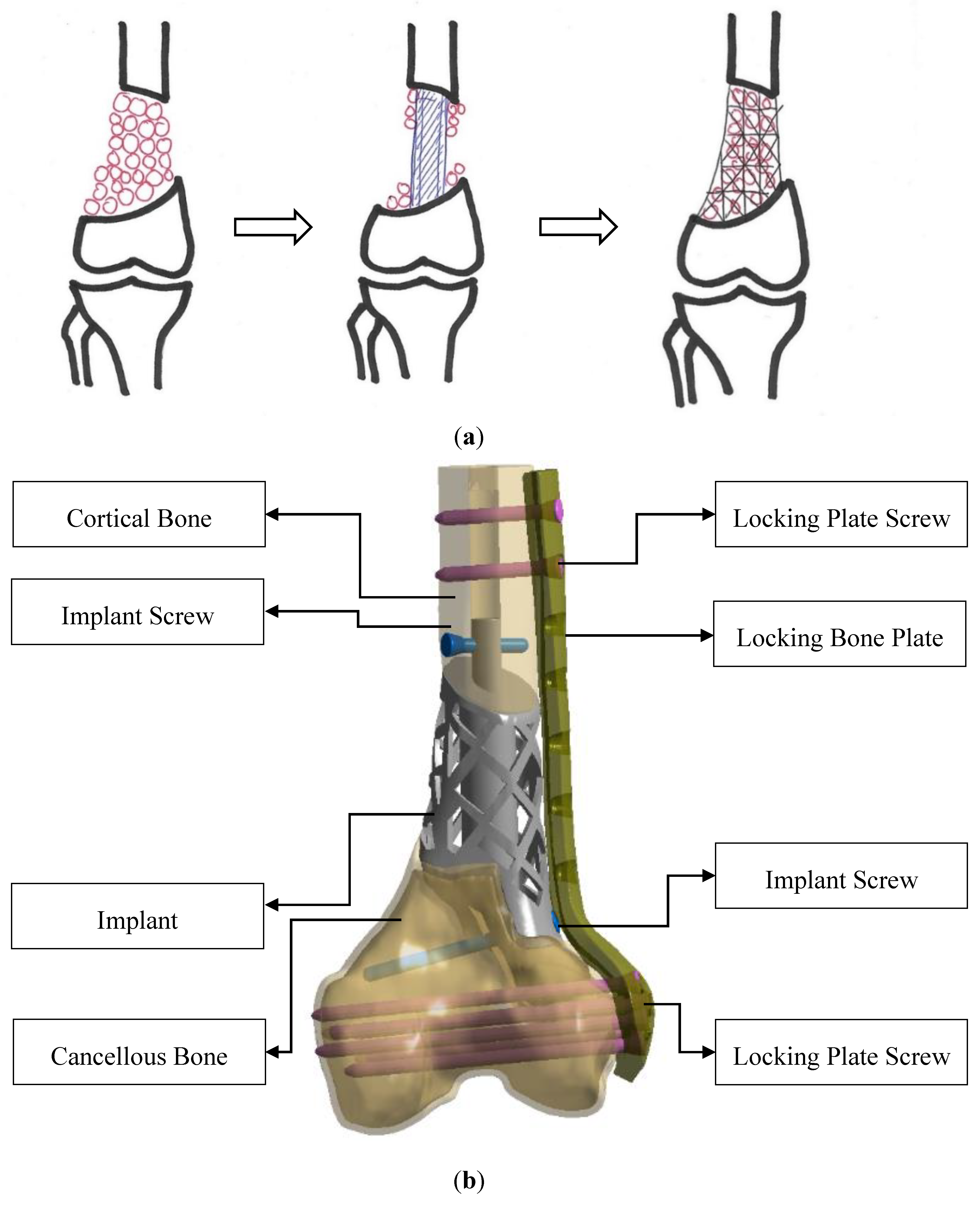
The distal right femur fracture and defect site of the distal right femur can be identified to perform the 3D printing titanium implant design. The implant’s 3-dimensional profile was configured to closely match the fracture site (Figure 2a). A central cylindrical tube was designed in the center of the implant to help provide mechanical stability. Proximal and distal shells 1.5 mm in thickness were designed on the implant to provide a contact structure to induce bone ingrowth. A protruding stem was considered to fit into the femoral canal at the proximal bone-implant junction with a transverse implant screw fixed with the proximal host bone. An additional oblique implant screw was also used to fix the implant at the distal host bone. A lattice mesh structure (10 mm × 10 mm) 1.5 mm in thickness was projected onto the implant surface to provide space for morselized cancellous bone grafting to enhance the implant’s structural strength. An outer lateral-side pre-contoured locking plate was applied at the lateral site with a 0.5 mm gap between the bone and plate to secure the entire construct (Figure 2b).

2.3. Non-Linear Finite Element Analysis

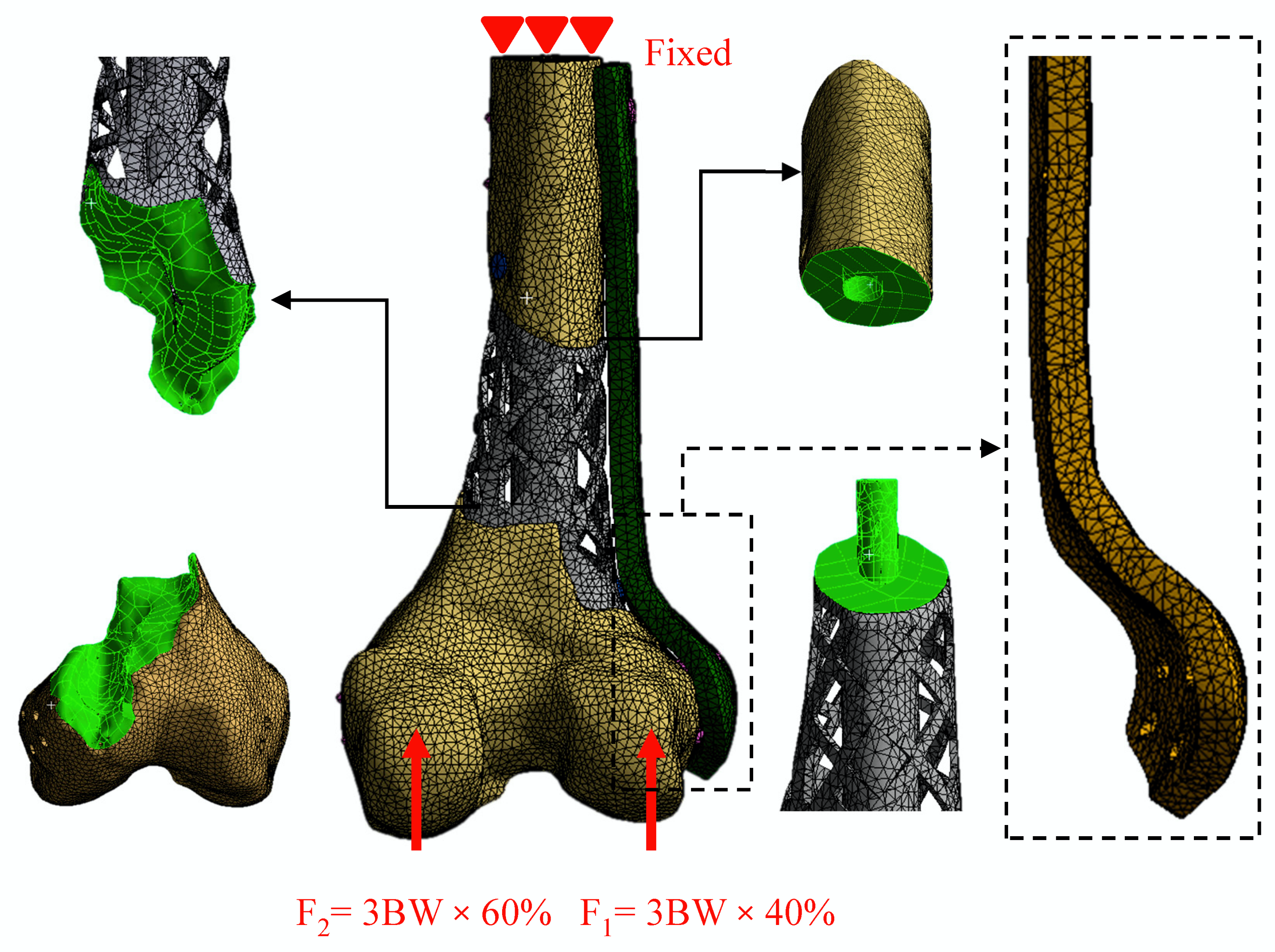
Solid models of the implant, screws, pre-contoured locking plate and remaining right femur were imported into ANSYS to assemble the corresponding bone fracture model. The resulting FE model was meshed using quadratic tetrahedral elements. The number of mesh elements and nodes were chosen based on convergence tests. The remaining femur, implant, screws and pre-contoured locking plate meshes were composed of 175,671, 32,869, 15,565 and 25,495 elements and 272,993, 60,457, 30,439 and 42,194 nodes, respectively (Figure 3). The proximal/distal implant fixation screws and pre-contoured plate locking screws were assumed to have continuous connections with the fixation plates, cortical, and cancellous bones. The bonded condition was used to mimic the screw/plate and screw/bone interfaces. All nodes were constrained at the proximal end as the boundary condition and elastic modulus and Poisson’s ratio material properties for cortical, cancellous bone, titanium implant, and locking plates/screws adopted from the literature [9,10]. The force was applied separately on the medial and lateral condyles. These loads correspond to 3 times the body weight (70 kg) distributed 40% on the lateral condyle (870 N) and 60% on the medial condyle (1160 N) of the stance phase before toe-off (Figure 3) [11,12].
Three different simulated conditions for FE analysis were set up to mimic the actual clinical stages. Stage 1 was assumed as the immediate postoperative period, i.e., bone union at the proximal/distal implant-bone interface was not yet complete. Nonlinear contact elements (defined as surface to surface) with friction coefficients of 0.2 were used to simulate the interfacial adaptation between the implant and bone surface. Stage 2 was assumed as the postoperative bone union model with the implant and locking plate in place. Bonded elements, i.e., displacement continuous between different materials, were used to simulate the bone union condition at the implant-bone interface. Stage 3 is assumed as the condition after locking plate removal when postoperative bone union is achieved. The von Mises strain distribution at the implant-bone interface, fracture femur displacements fixed with implant locking plate at different stages, and maximum von Mises stress and distributions were obtained to evaluate the biomechanical behavior.

3. Results

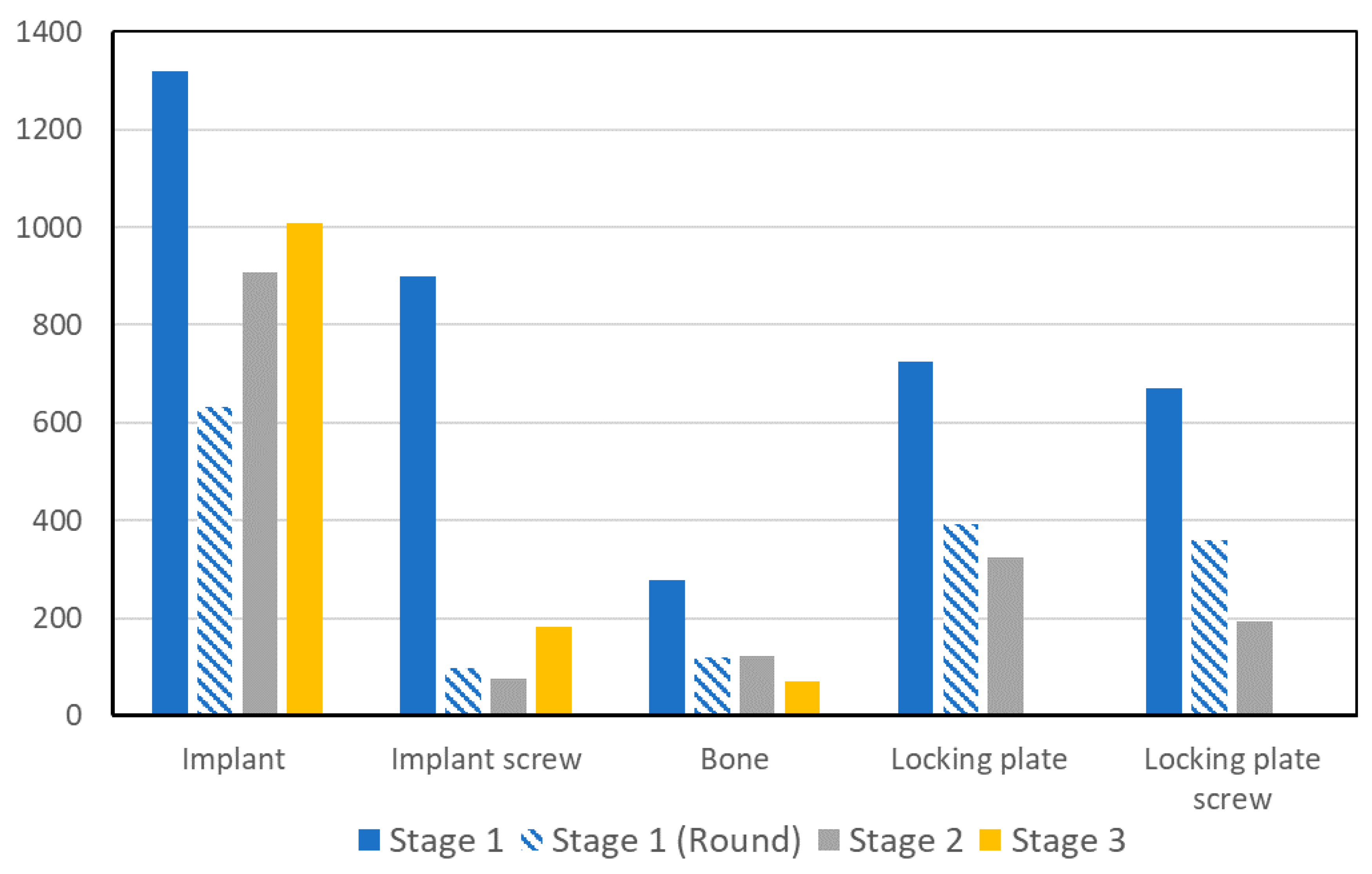
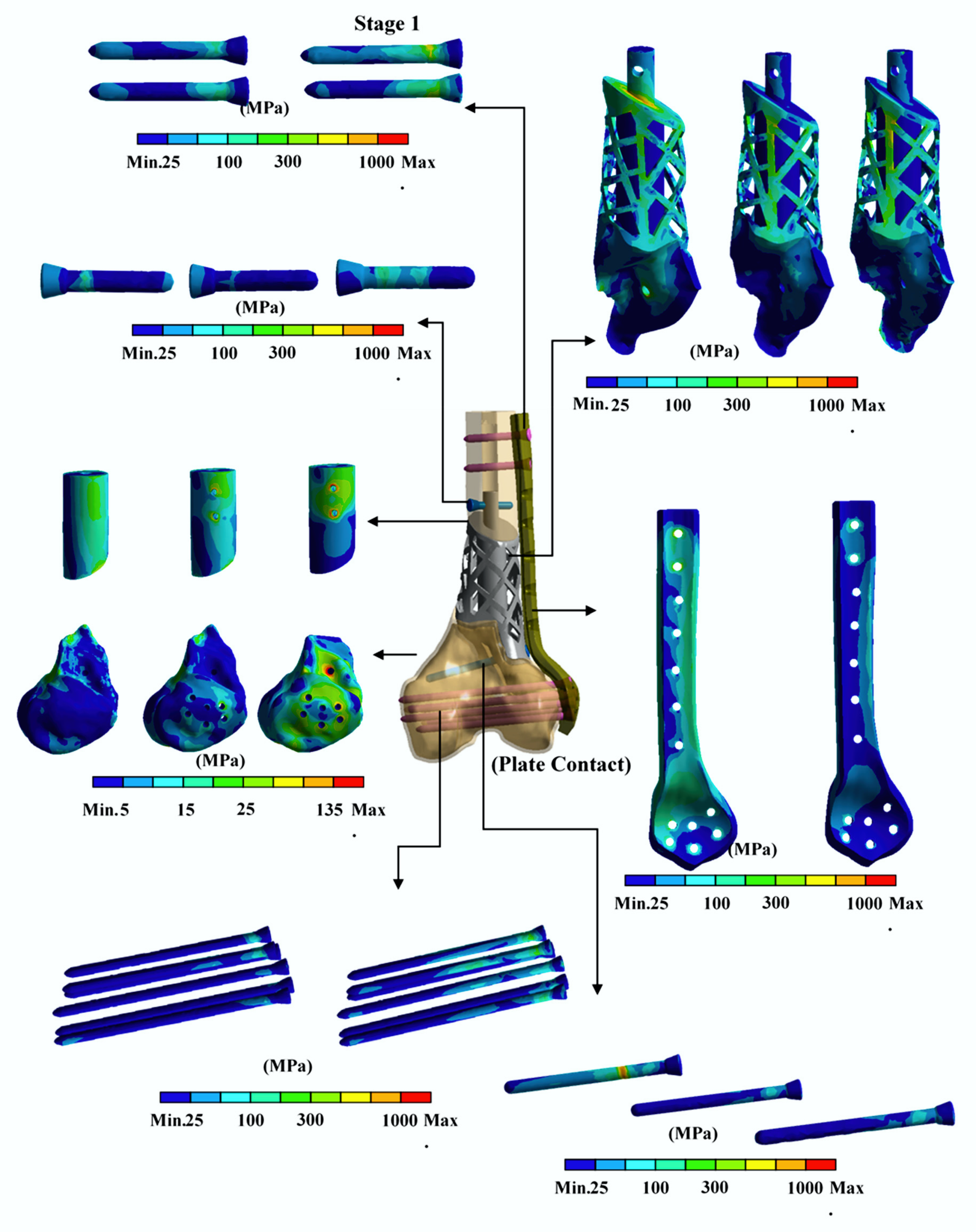
The FE analysis results showed that the maximum von Mises stresses for the implant, implant screw, bone, locking plate and locking plate screw all decreased significantly from stage 1 to stage 2. Bone stress continued to decrease from stage 2 to stage 3 but the implant and implant screw increased slightly. The maximum implant stress value reached 1318 MPa, which exceeded the fracture strength of the titanium alloy material (about 1000 MPa) in stage 1 (Figure 4). The von Mises stress distribution shows that the maximum stress value of the stage 1 implant occurred at the surface lattice mesh structure with apex region/implant stem for the implant, at the junction with the bone for bone, and at the implant screw and locking plate screw, while the locking plate’s occurred at the proximal end and locking plate screw junction (Figure 5).
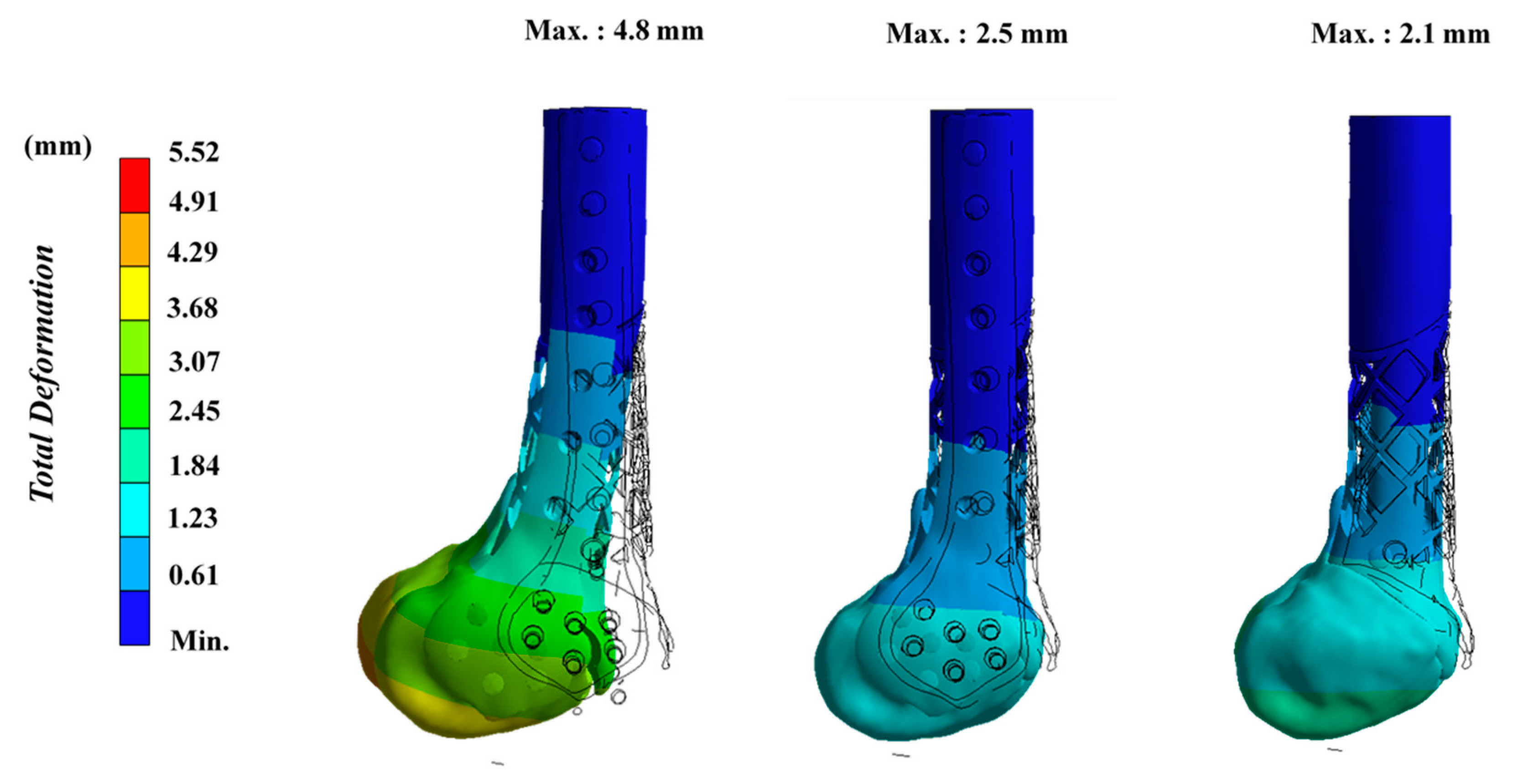
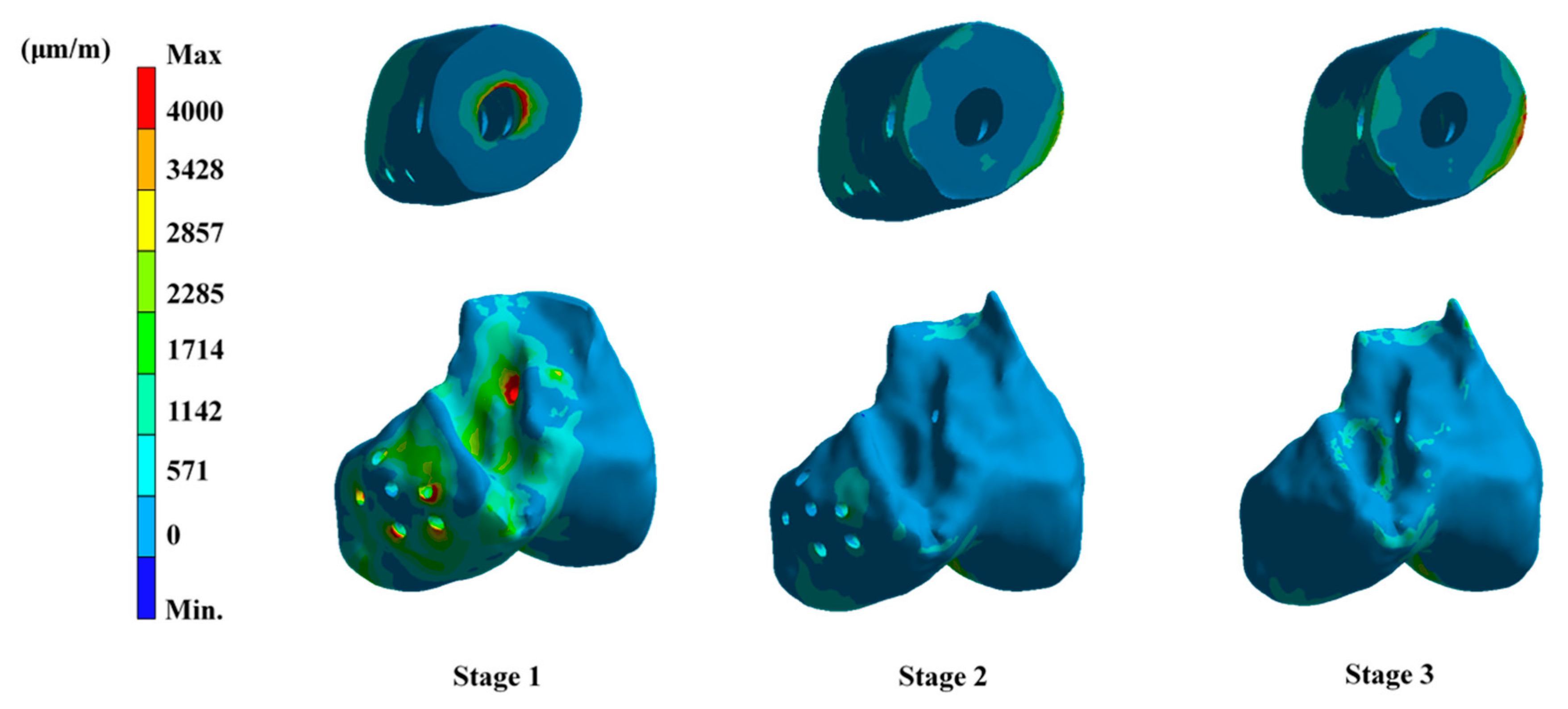
The overall displacement results can be found at the distal condyle of about 4.8 mm in stage 1, reduced to 2.5 mm with osseointegration and assisted by the locking plate in stage 2, and reduced to 2.1 mm after taking out the locking plate in stage 3 (Figure 6). Most of the strain values were less than 4000 at the proximal and distal implant-bone contact interfaces but only a small amount were more than 4000 around the proximal stem and the distal bone nail in stage 1 (Figure 7). While the corresponding strain value dropped significantly in stage 2, there was a slight increase at the proximal lateral site in stage 3.

4. Discussion

During the distal femur fracture with bone defect operation treatment, besides using bone grafts to fill the defect, other supporting implants such as lateral site pre-contoured locking plates are normally used to fix the fractures. Postoperative protection is usually required (partially or completely without weight-bearing). After 3–6 months, when the bone starts to heal, weight-bearing is slowly added. Because the locking plate position is close to the knee joint, patients often feel a foreign body sensation and even pain with restricted movement after the operation. Therefore, the locking plate can be removed after the bone is completely mended. Thus, three stages were set up in this study to simulate these three critical treatment time points. Stage 1 was the early surgical stage, with bone stability fixed mainly by the 3DP patient-specific implant, the locking plate, and screws. The more complete the fixation the better the initial stability. Stage 2 was the period after bone union is completed. The structural stability at this time should be the strongest, with the patient’s limb stability reaching optimum condition. Stage 3 was the time after the locking plate and screws are removed, while the femur and 3DP implant remained in situ.
One of the advantages of using FE analysis is that it is possible to simulate biomechanical performance for different stages. This cannot be achieved using traditional experimental methods. As described in the Introduction, although 3DP patient-specific titanium implants with good biocompatibility in regard to size and shape are a potential alternative to distal femur fracture with segmental large bone defect treatment, titanium implants are stiffer than natural bone and cause significant stress-shielding effects, leading to bone resorption and eventual implant failure [13,14]. A lightweight optimized structure that can withstand physiological loads from a biomechanical point of view is the highest guiding principle of 3DP applications in orthopedics.
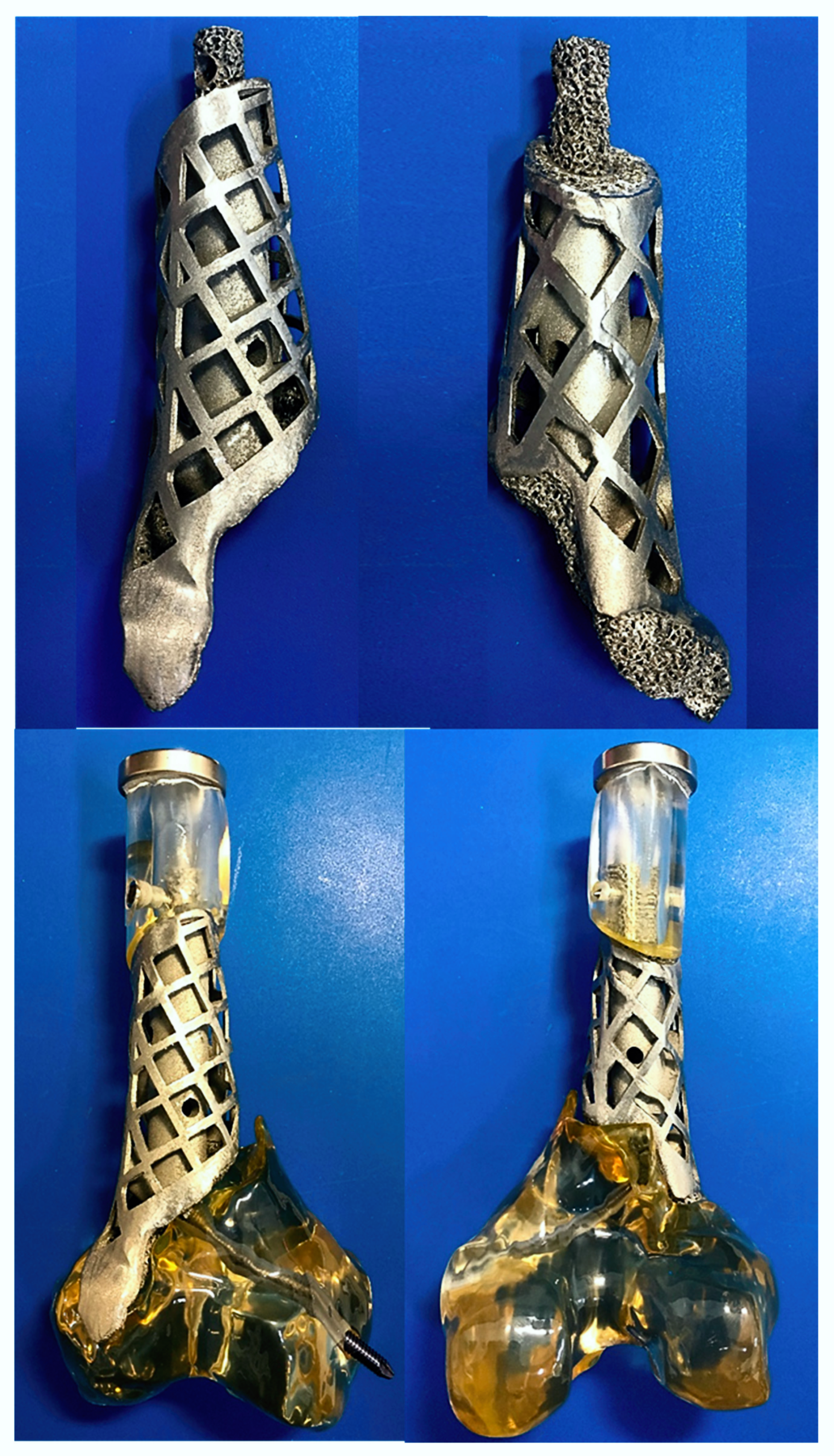
The proposed novel implant design was fabricated using AM400 titanium alloy printer (Renishaw, Gloucestershire, UK) (powder about 30 μm) using ISO13485 quality management systems research center (Taiwan Instrument Research Institute, Hsinchu, Taiwan). The implant was treated to delete residual sandblast particles and cleaned using ultrasonic oscillations (Figure 8). The manufactured implant has a lightweight design, with a solid weight of 107 g. The corresponding defect bone weight is 78 g. The implant is only 1.37 times heavier than the original bone, which is closer to the clinical need for replacing the defect bone.
Strain is an important indicator for bone healing/remodeling at the implant-bone interface [15]. Frost suggested that bone remodeling is initiated at some critical strain level in his “mechanostat theory” [16]. Rubin and Lanyon also pointed out that a newly formed bone area is proportional to the induced strain magnitude [17]. Critical damage strain over thresholds of 4000 μm could induce microdamage of bone cells and delay interface bone union or nonunion [18]. In stage 1 (immediate postoperative) before bone healing, the simulated results revealed that the implant-bone interface strain was mostly below 4000. This provided an environment conducive to bone healing. Unfortunately, the currently existing macro FE model for a fractured femur fixed with 3DP implant and locking plate was unable to simulate micro-porous structures at the implant-bone interface and subsequent bone growth due to scale issues. However, an implant surface with 600 μm porous hole structure can be accurately produced through 3DP technology (Figure 8). These porous structures can secure the construct stability and provide a good load transfer bonding area, especially in a weight-bearing bone such as the femur. Therefore, the implant-bone interface should easily promote complete bone healing in the presence of these porous structures.
In stage 1 the implant stress values are very high and exceed titanium alloy ultimate strength, inducing implant failure/fracture because the bone/implant interface has not been integrated. The highest implant stress value occurred on the outer lattice mesh structure. There is particularly high stress concentration at the mesh grid angles. This phenomenon can be greatly improved by rounding the angles to greatly decrease stress values (Figure 4 and Figure 9). In stage 2 the force can be effectively transmitted from bone to implant after the bone and implant have been integrated and the maximum stress value and system deformation can be greatly reduced. However, the implant stress, screws and proximal interface strain increased slightly after removing the locking plate in stage 3. From this observation, besides the implant the locking plate plays an important role in maintaining the initial construct stability. This also explains why an additional locking plate must be used for this kind of reconstruction surgery.
There were some limitations in this study. Materials with linear elastic (homogenous and isotropic) properties were used due to numerical convergence consideration. Only single leg standing was considered as the load condition and the micro-porous structure at the implant-bone interface cannot be simulated to understand micro-implant-bone interface integration using current FE macro modeling. In vitro biomechanical testing was challenging to perform due to the difficulty obtaining patient-specific artificial fracture bone with accurate material properties.

5. Conclusions

The proposed novel patient-specific 3DP implant design concept for a distal femoral fracture defect can effectively repair fractures and fulfill biomechanical requirement conditions under a single leg standing phase. However, note that the grid mesh structure should be designed with rounded angles.

Author Contributions

All authors have made substantial contributions to conception and design of the study. K.W.W. and C.D.W. have been involved in data collection and data analysis. C.-S.C., C.-W.L., T.-H.Y. and C.-L.L. have been involved in data interpretation, drafting the manuscript and revising it critically and have given final approval of the version to be published. All authors have read and agreed to the published version of the manuscript.

Funding

This study is supported in part by MOST project 108-2622-E-010 -001 -CC2 and 108-2622-B-010 -005, Taiwan.

Conflicts of Interest

The authors declare no conflict of interest.

References

  1. Keating, J.F.; Simpson, A.H.; Robinson, C.M. The management of fractures with bone loss. J. Bone Jt. Surg. Br. 2005, 87, 142–150. [Google Scholar] [CrossRef] [PubMed] [Green Version]
  2. Thakeb, M.F.; Mahran, M.A.; El-Motassem, H.M. Bone transport for the management of severely comminuted fractures without bone loss. Strateg. Trauma Limb Reconstr. 2016, 11, 19–24. [Google Scholar]
  3. Pipitone, P.S.; Rehman, S. Management of traumatic bone loss in the lower extremity. Orthop. Clin. N. Am. 2014, 45, 469–482. [Google Scholar] [CrossRef] [PubMed]
  4. Giotikas, D.; Tarazi, N.; Spalding, L.; Nabergoj, M.; Krkovic, M. Results of the Induced Membrane Technique in the Management of Traumatic Bone Loss in the Lower Limb: A Cohort Study. J. Orthop. Trauma 2019, 33, 131–136. [Google Scholar] [CrossRef] [PubMed]
  5. Jacek, B.; Maciej, P.; Tomasz, P.; Agata, B.; Wiesław, K.; Radosław, W.; Filip, G. 3D printed models in mandibular reconstruction with bony free flaps. J. Mater. Sci. Mater. Med. 2018, 29, 23. [Google Scholar] [CrossRef] [PubMed] [Green Version]
  6. Mangano, C.; Bianchi, A.; Mangano, C.; Dana, J.; Colombo, M.; Solop, I.; Admakin, O. Custom-made 3D printed subperiosteal titanium implants for the prosthetic restoration of the atrophic posterior mandible of elderly patients: A case series. 3D Print Med. 2020, 6, 1–14. [Google Scholar] [CrossRef] [PubMed] [Green Version]
  7. Tetsworth, K.; Block, S.; Glatt, V. Putting 3D modelling and 3D printing into practice: Virtual surgery and preoperative planning to reconstruct complex post-traumatic skeletal deformities and defects. SICOT J. 2017, 3, 16. [Google Scholar] [CrossRef] [PubMed]
  8. Hamid, K.S.; Parekh, S.G.; Adams, S.B. Salvage of Severe Foot and Ankle Trauma with a 3D Printed Scaffold. Foot Ankle Int. 2016, 37, 433–439. [Google Scholar] [CrossRef] [PubMed]
  9. Gesensway, D.; Putnam, M.D.; Mente, P.L.; Lewis, J.L. Design and biomechanics of a plate for the distal radius. J. Hand Surg Am. 1995, 20, 1021–1027. [Google Scholar] [CrossRef]
  10. Reeves, J.M.; Burkhart, T.A.; Dunning, C.E. The effect of static muscle forces on the fracture strength of the intact distal radius in vitro in response to simulated forward fall impacts. J. Biomech. 2014, 47, 2672–2678. [Google Scholar] [CrossRef] [PubMed]
  11. Completo, A.; Fonseca, F.; Simões, J. Experimental validation of intact and implanted distal femur finite element models. J. Biomech. 2007, 40, 2467–2476. [Google Scholar] [CrossRef] [PubMed]
  12. Conlisk, N.; Howie, C.R.; Pankaj, P. Optimum stem length for mitigation of periprosthetic fracture risk following primary total knee arthroplasty: A finite element study. Knee Surgery, Sports Traumatology. Arthroscopy 2018, 26, 1420–1428. [Google Scholar]
  13. Long, M.; Rack, H. Titanium alloys in total joint replacement—A materials science perspective. Biomaterials 1998, 19, 1621–1639. [Google Scholar] [CrossRef]
  14. Cheng, K.; Liu, Y.; Yao, C.; Zhao, W.; Xu, X. A personalized mandibular implant with supporting and porous structures designed with topology optimization—A case study of canine. Rapid Prototyp. J. 2019, 25, 417–426. [Google Scholar] [CrossRef]
  15. Çehreli, M.; Şahin, S.; Akça, K. Role of mechanical environment and implant design on bone tissue differentiation: Current knowledge and future contexts. J. Dent. 2004, 32, 123–132. [Google Scholar] [CrossRef] [PubMed]
  16. Frost, H.M. Wolff’s Law and bone’s structural adaptations to mechanical usage: An overview for clinicians. Angle Orthod. 1994, 64, 175–188. [Google Scholar] [PubMed]
  17. Rubin, C.T.; Lanyon, L.E. Regulation of bone mass by mechanical strain magnitude. Calcif. Tissue Int. 1985, 37, 411–417. [Google Scholar] [CrossRef] [PubMed]
  18. Pattin, C.; Caler, W.; Carter, D. Cyclic mechanical property degradation during fatigue loading of cortical bone. J. Biomech. 1996, 29, 69–79. [Google Scholar] [CrossRef]
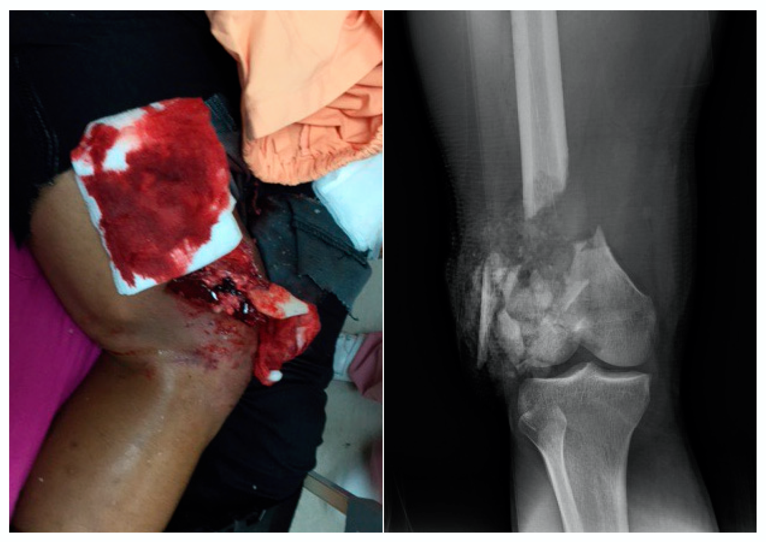
Figure 1. A 17 y/o patient with right distal femur fracture with >15 cm open wound. The X-ray showed severe comminution of the fracture with large segmental bone defect.
Applsci 10 04098 g001
Figure 2. (a) Traditional surgical reconstruction methods using morselized bone graft (red circle) alone and strut graft (blue cylinder) with morselized bone graft. This novel implant perfectly matches the fracture site and fills up the defect. Bone graft can be protected within the implant. (b) Illustration model of the construct. The patient specific 3D printing titanium implant fit into the bone defect and fixed with host bone with implant screws. Additional lateral site pre-contoured locking plate was applied to secure the construct.
Applsci 10 04098 g002
Figure 3. FE model consisted of the implant, screws, pre-contoured locking plate, and remaining right femur. Light green area showed the proximal and distal bone-implant contact interface. The force was applied separately on the medial condyle (60%) and the lateral condyle (40%), with correspond to 3 times of body weight.
Applsci 10 04098 g003
Figure 4. The result of FE analysis for the von Mises stresses for implant, implant screw, locking plate and locking screw at different simulated stages. The value decreased by half after we introduced the rounded angle design into the implant.
Applsci 10 04098 g004
Figure 5. The maximum stress distribution area in the stage 1 occurred at the surface lattice mesh structure with apex region/implant stem for the implant, at the bone-implant interface for the bone, the implant screws, the locking plate and the locking plate screws. Significant decrease of stress can be observed with progress into the second and third stage.
Applsci 10 04098 g005
Figure 6. Overall displacement of the construct can be found at the distal condyle and was about 4.8 mm in the first stage. It was reduced to 2.5 mm with completion of osseointegration in the second stage and can be reduced to 2.1 mm after removing the locking plate in the third stage.
Applsci 10 04098 g006
Figure 7. Most of the strain values were less than 4000 at the proximal and distal implant-bone contact interfaces and only a small amount was more than 4000 around the proximal stem and the distal bone nail in the stage 1.
Applsci 10 04098 g007
Figure 8. The novel patient specific 3DP titanium implant. Note the central solid cylinder and the outer lattice structure of the implant body, with protected spaces for the morselized bone graft. The perfectly fit bone-implant interface of the implant consists of the proximal shell with a stem and the distal shell, both with unique porous structures facilitating osteointegration.
Applsci 10 04098 g008
Figure 9. Design optimization of the implant lattice structure from acute angle to rounded angle greatly decreased the implant stress value in the first stage to around 600 MPa, which is much lower than the fracture strength of the titanium alloy material (about 1000 MPa).
Applsci 10 04098 g009