Article

A Flexible FPGA-Based Channel Emulator for Non-Stationary MIMO Fading Channels

1
The Key Laboratory of Dynamic Cognitive System of Electromagnetic Spectrum Space, College of Electronic and Information Engineering, Nanjing University of Aeronautics and Astronautics, Nanjing 211106, China
2
The Key Laboratory of Dynamic Cognitive System of Electromagnetic Spectrum Space, College of Astronautics, Nanjing University of Aeronautics and Astronautics, Nanjing 211106, China
*
Author to whom correspondence should be addressed.
Appl. Sci. 2020, 10(12), 4161; https://doi.org/10.3390/app10124161
Submission received: 13 May 2020 / Revised: 11 June 2020 / Accepted: 13 June 2020 / Published: 17 June 2020

Abstract

:
In this paper, a discrete non-stationary multiple-input multiple-output (MIMO) channel model suitable for the fixed-point realization on the field-programmable gate array (FPGA) hardware platform is proposed. On this basis, we develop a flexible hardware architecture with configurable channel parameters and implement it on a non-stationary MIMO channel emulator in a single FPGA chip. In addition, an improved non-stationary channel emulation method is employed to guarantee accurate channel fading and phase, and the schemes of other key modules are also illustrated and implemented in a single FPGA chip. Hardware tests demonstrate that the output statistical properties of proposed channel emulator, i.e., the probability density function (PDF), cross-correlation function (CCF), Doppler power spectrum density (DPSD), and the power delay profile (PDP) agree well with the corresponding theoretical ones.

1. Introduction

Multiple-input multiple-output (MIMO) technologies have played an important role in the fifth generation (5G) and previous communication systems [1,2,3], as they can boost channel capacity and improve spectral efficiency without increasing transmitting power or system bandwidth [4,5]. It is inevitable to evaluate and validate the performance of MIMO communication devices during the development. The most realistic method is field testing, but it is uncontrollable, unrepeatable, and expensive. Channel emulators can reproduce the real propagation scenario in a controllable way and is a good alternative so far [6].
There are several commercial channel emulators such as Agilent’s N5106A PXB, Keysight’s Propsim F32 [7], and Azimuth’s ACE 400WB [8]. However, these emulators are very large, expensive, and complicated, and mainly developed for the standard channel models, which are all based on the wide-sense stationary (WSS) assumption. Meanwhile, various academic researches on hardware emulation can be found in [9,10,11,12,13,14,15,16,17,18], which were focused on the emulation of stationary channel models [9,10,11,12]. However, recent measurements have proved that the stationary channel model is not suitable for certain propagation scenarios [13,14,15,16,17,18], such as high-speed train (HST) [16,17], vehicle-to-vehicle (V2V) [13,14,15], and unmanned aerial vehicle (UAV) channels [18].
There are very limited non-stationary channel emulators reported in the literatures [19,20,21,22,23,24,25,26,27]. A hardware emulator for the discrete-time triply selective fading channel was developed in [19]. The channel coefficients were calculated by software dynamically, which cannot support real-time updating. The authors in [20,21] proposed an improved sum-of-sinusoid (SoS) method to generate channel fading, and implemented it into a 2 × 2 non-stationary MIMO channel emulator. A 4 × 4 MIMO channel emulator was designed in [22], but the authors did not give the details of implementation. In [23,24], two specific MIMO channel emulators for high speed WLAN 802.ac and LTE-A channels were developed, respectively. In [25], the authors divided the non-stationary channel into several stationary channel segments and adopted the traditional stationary channel emulation method. The authors in [26] designed a channel emulator based on software defined radios (SDR) platform, but the emulator can only be applied to vehicular communications. To the best of our knowledge, the aforementioned channel emulators still adopted traditional stationary channel models and considered the non-stationary aspect by updating parameters periodically. However, we have found that the output fading phases of this kind of method are not accurate, which leads to the output Doppler power spectrum density (DPSD) not fitting well with the theoretical ones [28]. To overcome this shortcoming, an improved 3D non-stationary geometry-based stochastic model (GBSM) was proposed in [27] and implemented in a 2 × 2 MIMO channel emulator. However, the developed hardware was only suitable for the corresponding channel model and the structure was not general and flexible. This paper proposes a discrete non-stationary channel model with accurate channel fading and phase. The channel parameters such as power, delay, and Doppler frequency are all time-variant in order to take the non-stationarity into account. Furthermore, a flexible hardware architecture is proposed and implemented in a single FPGA chip. Finally, we validate the correctness of the proposed channel model as well as the hardware emulator. The major contributions are summarized as follows.
  • Based on the improved GBSM with the accurate channel fading phase and Doppler frequency in [27], this paper proposes a discrete non-stationary MIMO channel model, which is suitable to implement on the FPGA-based hardware platforms. Meanwhile, a flexible hardware architecture tailored for the proposed model is developed, in which the channel size and parameters can easily be reconfigured.
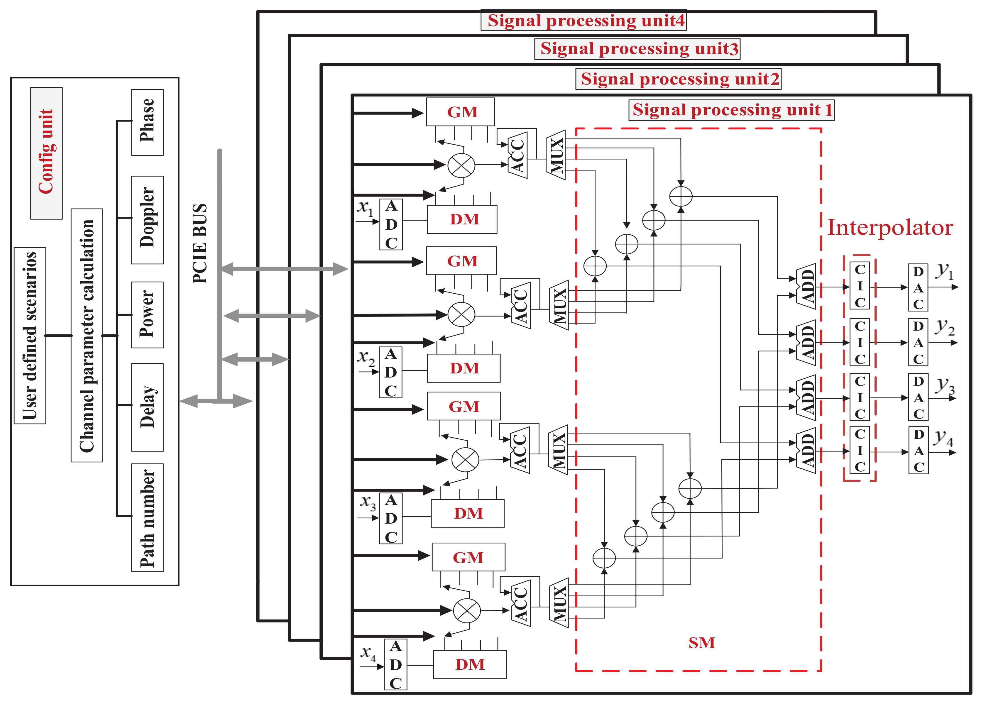
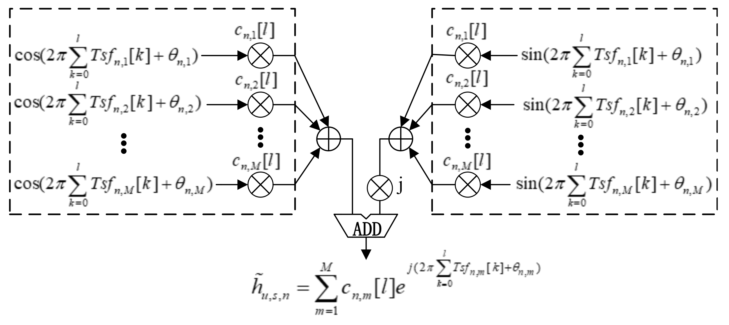
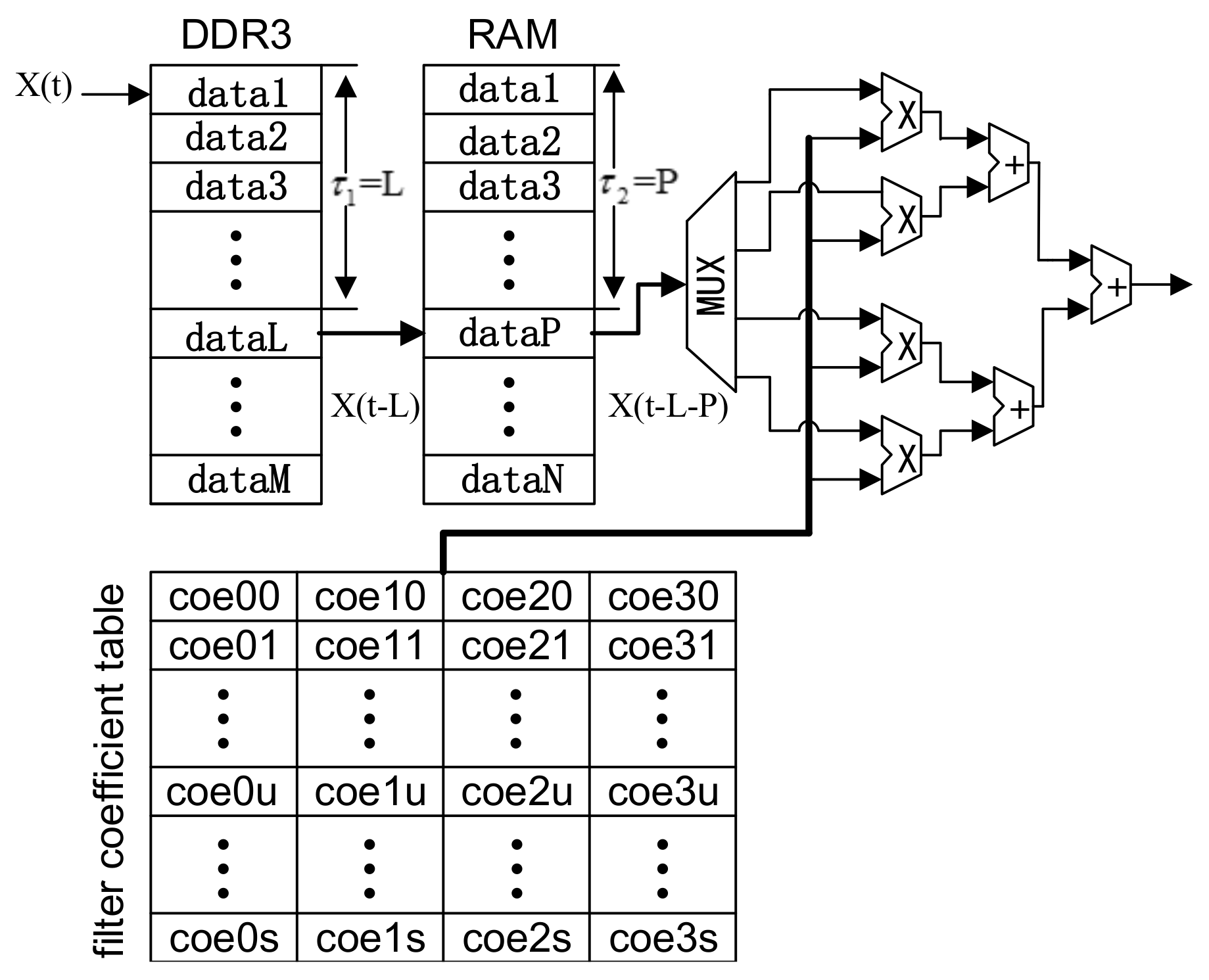
  • An improved emulation method of channel fading, namely, sum-of-frequency-modulated-signals (SoFM), is employed to guarantee the accurate channel fading and phase. In addition, the architectures of other key modules, i.e., the delay module, fading generation module, and interpolator module, are developed and implemented on a single Xilinx XC7VX690T FPGA.
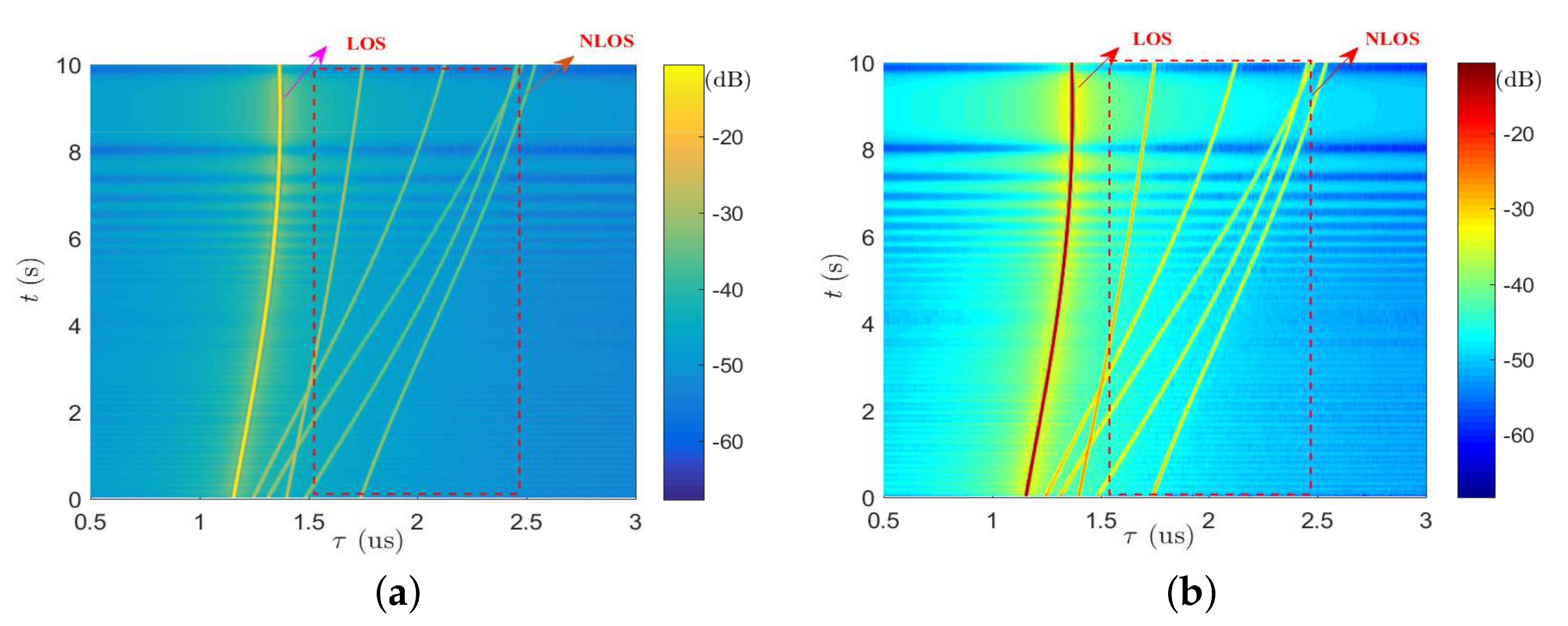
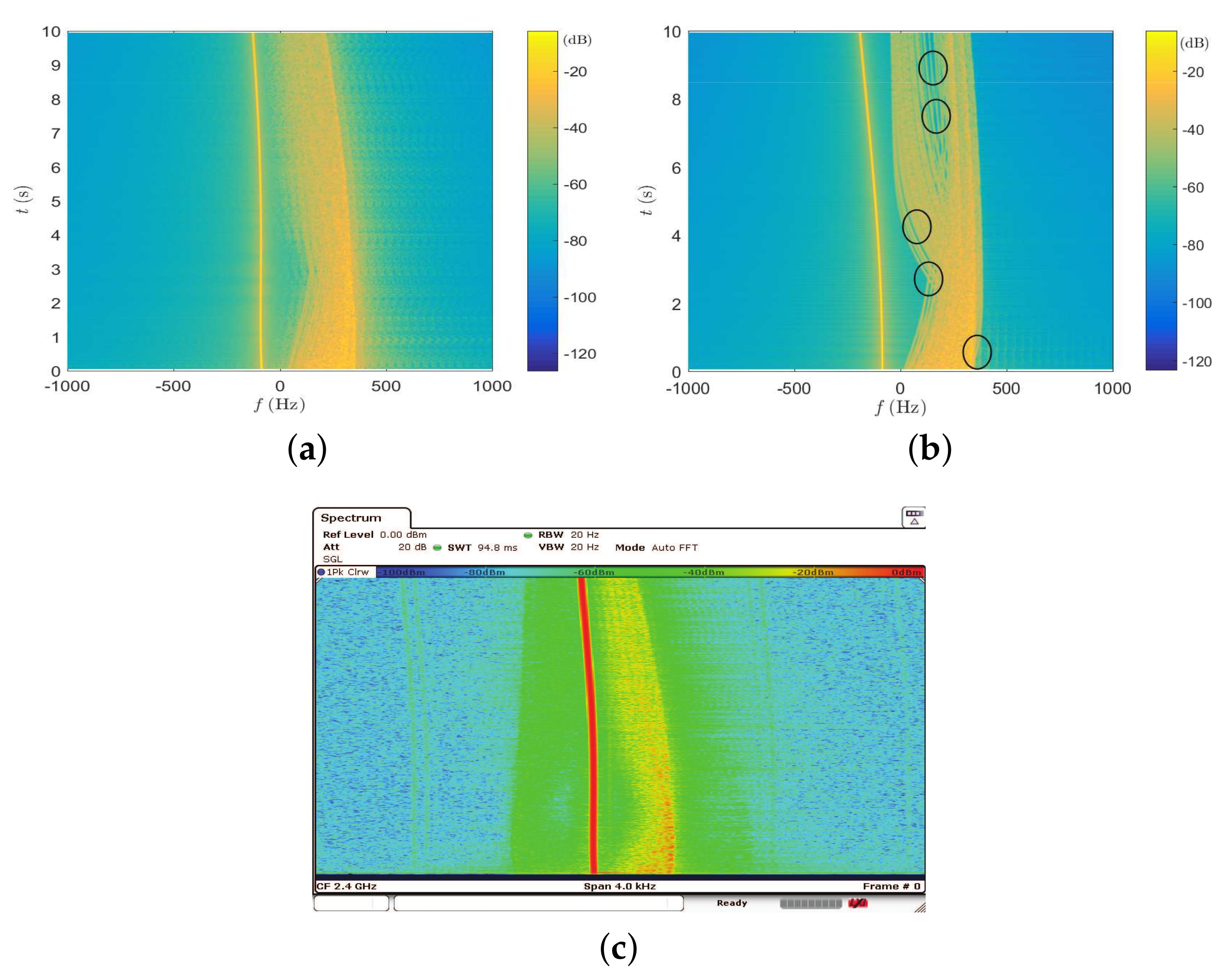
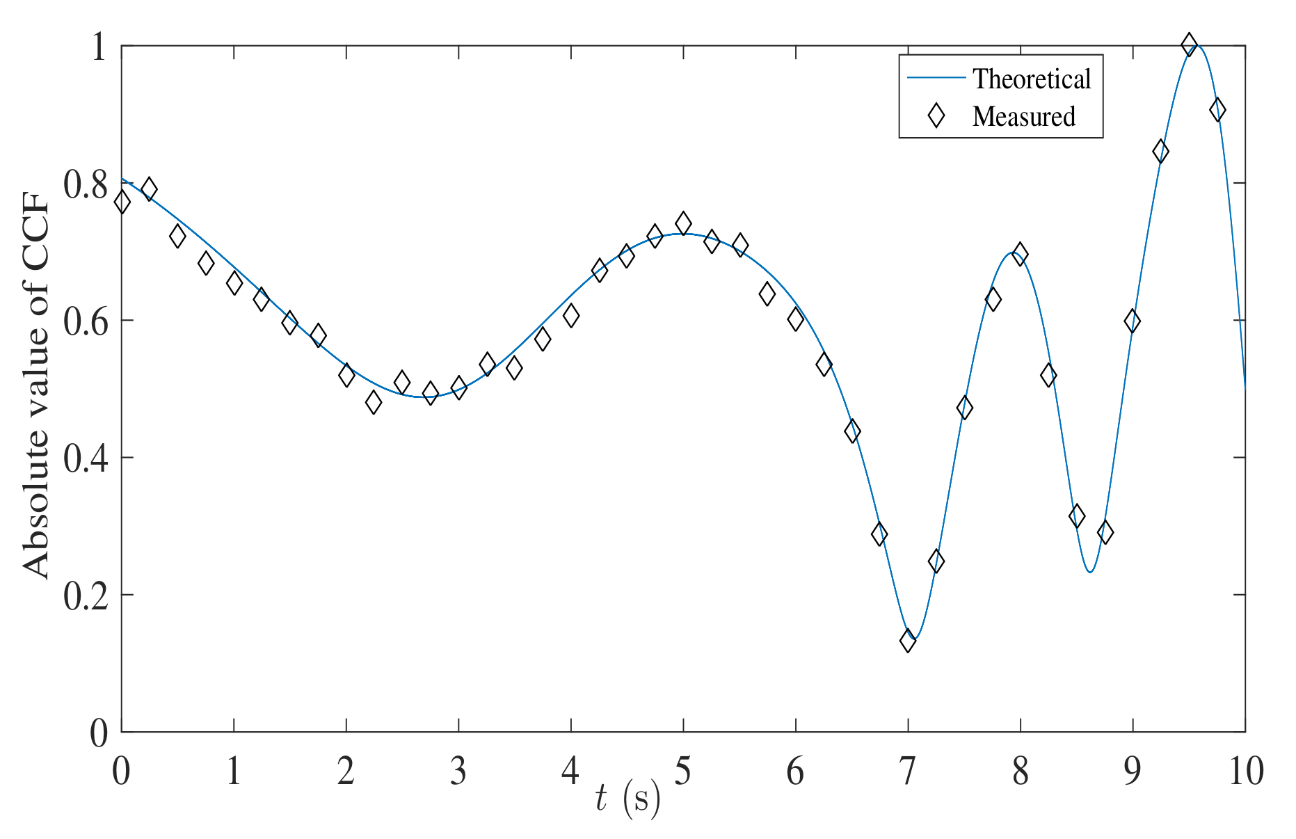
  • For the developed channel emulator, the output statistical properties, i.e., the probability density function (PDF), cross-correlation function (CCF), and DPSD are tested and verified by the theoretical results. The power delay profile (PDP) is also validated by the measurement data.
The rest of this paper is organized as follows. In Section 2, a discrete non-stationary MIMO channel model is briefly introduced. Section 3 proposes the hardware architecture of channel emulator as well as the channel fading emulation algorithm. In addition, the detailed implementation of key modules are also presented. In Section 4, the developed channel emulator is tested and validated. Finally, some conclusions are drawn in Section 5.

2. Discrete Non-Stationary MIMO Channel Model

Considering a MIMO channel with S transmitting antennas and U receiving antennas, the channel can be defined by a complex channel matrix. Moreover, the input–output relationship in the discrete time domain can be expressed by a convolution operation as
y ( l ) = H ( l , ζ ) x ( l )
where x ( l ) = [ x 1 ( l ) , x 2 ( l ) , , x S ( l ) ] T is the transmitted signal vector; y ( l ) = [ y 1 ( l ) , y 2 ( l ) , , y U ( l ) ] T is the received signal vector; l and ζ are the discrete time indexes in the time domain and delay domain, respectively; and ( · ) T denotes the transpose operator of a matrix or vector. In (1), the channel matrix H ( l , ζ ) can be further defined as
H U × S l , ζ = h 1 , 1 l , ζ h 1 , 2 l , ζ h 1 , S l , ζ h 2 , 1 l , ζ h 2 , 2 l , ζ h 2 , S l , ζ h U , 1 l , ζ h U , 2 l , ζ h U , S l , ζ
where h u , s ( l , ζ ) denotes the channel impulse response (CIR) of the sub-channel between the uth ( u = 1 , 2 , , U ) receiving antenna and the sth ( s = 1 , 2 , , S ) transmitting antenna, and it can be modeled in the discrete time domain as [20]
h u , s ( l , ζ ) = n = 1 N l P n l h ˜ u , s , n ( l ) δ ( ζ τ n ( l ) T s )
where P n ( l ) and N ( l ) are the path power and valid path number at time instant l, respectively; h ˜ u , s , n ( l ) is the channel coefficient with the normalized power; T s is the sampling interval; and τ n ( l ) T s denotes the discrete time delay. It should be noticed that the channel parameters in (3), such as P n ( l ) , N ( l ) , τ n ( l ) T s , and h ˜ u , s , n ( l ) , are all time-variant, which can take into account the non-stationary aspects of real MIMO channels.

3. Flexible Hardware Architecture and Implementation

3.1. System Architecture

The flexible architecture of our proposed channel emulator is presented in Figure 1. It includes two primary units: the config unit and the signal processing unit. The config unit consists of user-defined scenario module and channel parameters calculation module. It provides an interactive interface for setting environment related parameters, and then calculates the channel parameters, i.e., the path number, delay, power, Doppler frequency, and phase. These channel parameters are passed through by the peripheral component interconnect express (PCIE) bus to the signal processing unit. Each signal processing unit has a four-channel structure with the analog-to-digital converters (ADC), digital-to-analog converters (DAC), and FPGA. Thus, a single signal processing unit can implement a 4 × 4 MIMO channel emulation. It should be noted that the proposed system architecture is flexible and theoretically supports arbitrary scaled MIMO channels within the limitation of transmission rate of PCIE.
The signal processing unit in Figure 1 is the most important and difficult part and it generates and superposes the multiple channel fading in real-time. Due to the flexibility and parallelism, FPGA is adopted as the core operation chip in the signal processing unit. It includes three modules: delay module (DM), generation module (GM), and superposition module (SM). The first module realizes the predefined delay of each propagation path, the second module generates channel fading coefficients, and the last one carries out the superposition operation and outputs the signal. As we can see, the final output can be expressed as
y 1 l y 2 l y 3 l y 4 l = n = 1 N l P n ζ h ˜ 1 , 1 , n ( ζ ) x 1 ( ζ τ n ( l ) T s ) + + n = 1 N l P n ζ h ˜ 1 , 4 , n ( ζ ) x 4 ( ζ τ n ( l ) T s ) n = 1 N l P n ζ h ˜ 2 , 1 , n ( ζ ) x 1 ( ζ τ n ( l ) T s ) + + n = 1 N l P n ζ h ˜ 2 , 4 , n ( ζ ) x 4 ( ζ τ n ( l ) T s ) n = 1 N l P n ζ h ˜ 3 , 1 , n ( ζ ) x 1 ( ζ τ n ( l ) T s ) + + n = 1 N l P n ζ h ˜ 3 , 4 , n ( ζ ) x 4 ( ζ τ n ( l ) T s ) n = 1 N l P n ζ h ˜ 4 , 1 , n ( ζ ) x 1 ( ζ τ n ( l ) T s ) + + n = 1 N l P n ζ h ˜ 4 , 4 , n ( ζ ) x 4 ( ζ τ n ( l ) T s )
which is equivalent with the theoretical result obtained from (1)–(3).

3.2. Channel Fading Generation

Several methods for generating the channel fading coefficients, i.e., SoC method, Doppler filter method, AR method, and their derivatives can be addressed in [10,11,28,29]. However, these methods can only be used for stationary channels with fixed channel parameters. In this paper, we upgrade the traditional SoC method to the non-stationary channel fading generation. In order to guarantee the continuity of output fading phase, we use an improved method to generate non-stationary channel as shown in Figure 2. The non-stationary fading coefficient can be generated based on the summation of several linear frequency modulated signals as
h ˜ u , s , n l = m = 1 M c n , m l e j 2 π k = 0 l T s f n , m [ k ] + θ n , m
where l is the discrete time index, M is the number of frequency modulated signal, c n , m denotes the sub-path gain, and f n , m and θ n , m are the discrete Doppler frequency and initial phase, respectively.
Note that the initial random phase of each branch is uniformly distributed over [ π , π ) and time-invariant. Considering the complexity of hardware implementation, it is assumed that the sub-path gain has the same value and does not change over time. Hold the condition of normalized path power, the sub-path gain of each branch equals to 1 1 N N . As the time-variant discrete Doppler frequency would increase the complexity and uncertainty, it is very important to find an efficient way to update the Doppler frequency parameter over time. The theoretical Doppler frequency of the mth sub-path within the nth path can be defined by [27]
f n , m ( l ) = k v M S r ^ M S , n , m ( l ) 2 π
where k = 2 π f c / c denotes the wave number, f c is the carrier frequency, c refers to the speed of light, v M S denotes the vector of the mobile station (MS) velocity, and r ^ M S , n , m is the arrival angle unit vector of the mth sub-path within the nth path. As the Doppler frequency is usually much smaller than the system sampling rate, it is assumed that the statistical properties maintain unchanged within several sampling intervals, i.e., stationary interval T u , which ranges from several millisecond to dozens of millisecond. The Doppler frequency of the mth sub-path within the uth interval, denoted as f n , m u , can be obtained by (6). In addition, we assume the discrete frequency parameters following the linear change within each interval T u . Then, the Doppler frequency within the uth stationary interval can be expressed as
f n , m u ( l ) = a n , m u + b m u ( l ( u 1 ) T u ) + Δ n , m u ( l )
where a n , m u denotes the initial value of the mth sub-path within the nth path, b m u is the slope of the mth sub-path, Δ n , m u ( l ) is the small random offset of the frequency parameter, a n , m u is random variable and distributes uniformly over [ F m 1 1 , F m 1 ) when u = 1 , and a n , m u stays the value at the end of previous interval when u = 2 , 3 , . Finally, the slope b m u can be calculated by
b m u = L ( F m u F m 1 u ) + ( F m u + 1 F m 1 u + 1 ) 2 T u
where L denotes the total number of the slope changes within each interval. In order to improve the performance, the following conditions for discrete Doppler frequency should be fulfilled [28],
f n , m 0 , n , m f n , m f n , q , n and m q

3.3. FPGA-Based Implementation

3.3.1. Delay Module

The delay module plays an important role in the channel emulation. It should be noted that the realization of multiple path delay is mainly based on the random access memory (RAM) or first input first output (FIFO). This method is easy to implement in FPGA, but cannot achieve the long-time delay, i.e., the aerial communication case, and high-precision delay, i.e., the indoor communication case. Especially, if the delay is relatively large, this method consumes a large amount of storage resources, which makes it impossible to realize in FPGA. To overcome this shortcoming, we adopt an external double-data-rate three synchronous dynamic random access memory (DDR3) and an interpolation filter to our scheme as shown in Figure 3. It includes three primary parts: DDR3, RAM, and high-precision interpolation filter. Take the advantage of large storage space of DDR3, it can achieve the large delay. Moreover, the data from RAM is multiplied by the coefficients of interpolation filter to achieve a high-precision delay. Thus, this scheme can adapt to a wide range of communication channels.
In order to validate the proposed scheme of delay module, we run the module by modelsim software under the scenario of 3 GPP modified vehicular-A channel (MVA) [30]. In the simulation, the system sampling clock is 100 MHz, that is to say, the clock period is 10 ns. As the delay resolution in MVA is 5 ns, the interpolation filter is designed as a two-time interpolator. Figure 4 shows the corresponding output signal when a pulse signal passes through the delay module. Taking the first path as the reference path, the relative delay of each path is set as 375 ns, 750 ns, 1125 ns, 1750 ns, and 250 ns, respectively. It can be seen that the simulated results are consistent with the desired ones, which validates the effectiveness of this method.

3.3.2. Fading Generation Module

For an arbitrary U × S MIMO channel, the number of channel fading generation module should be U × S × N and they could consume huge of hardware resources. As the maximum Doppler frequency is usually much smaller than the system sampling rate, in this paper we use a low initial sampling rate f s to generate the channel fading, which can greatly reduce the hardware consumption. The implementation scheme of channel fading generation is showed in Figure 5. First, the parameter module updates the Doppler frequency and phase in real time. Then, it passes them to the subtractor (SUB), accumulator (ACC), multiplier, and adder (ADD) to complete the corresponding integral operations and generate a look-up table (LUT) address. The values of the cosine function stored in the cosine table can be found by the LUT address, and they are superimposed by the accumulator to obtain the channel fading coefficient. Finally, the cascaded integrator comb (CIC) filter is used to interpolate and match the data rate.
According to the central limit theorem, the larger the number of sub-path, the closer the output channel fading is to the theoretical distribution. Considering a trade-off between the resource consumption and complexity, the number of sub-path is set as N = 64 . The data width of LUT is set to 16 bits and the data depth is set to 12 bits. We use the idea of serial and time-division multiplexing to find the phase address in the LUT efficiently. Considering the symmetry of cosine function, only a quarter of cosine period needs to be stored, and thus the data width and depth are 15 bits and 10 bits, respectively. Note that this can significantly save the RAM resource when the sub-path number becomes large. Figure 6 shows the simulation result of hardware implementation. In this figure, only the first three sub-paths, i.e., three FM signals, and the superposition of 64 branches are given. As we can see that the output fading envelope is random fluctuation and it should approximate to the Rayleigh distribution according to the central limit theorem. For the latency of hardware, with the help of integrated logical analyzer (ILA) debugging tool, we find that it takes three clock cycles to reach the steady state and 16 clock cycles totally to output the first valid channel data. As the system clock is 100 MHz, the latency of proposed hardware emulator is about 16 × 10 9 / ( 100 × 10 6 ) = 160 ns.

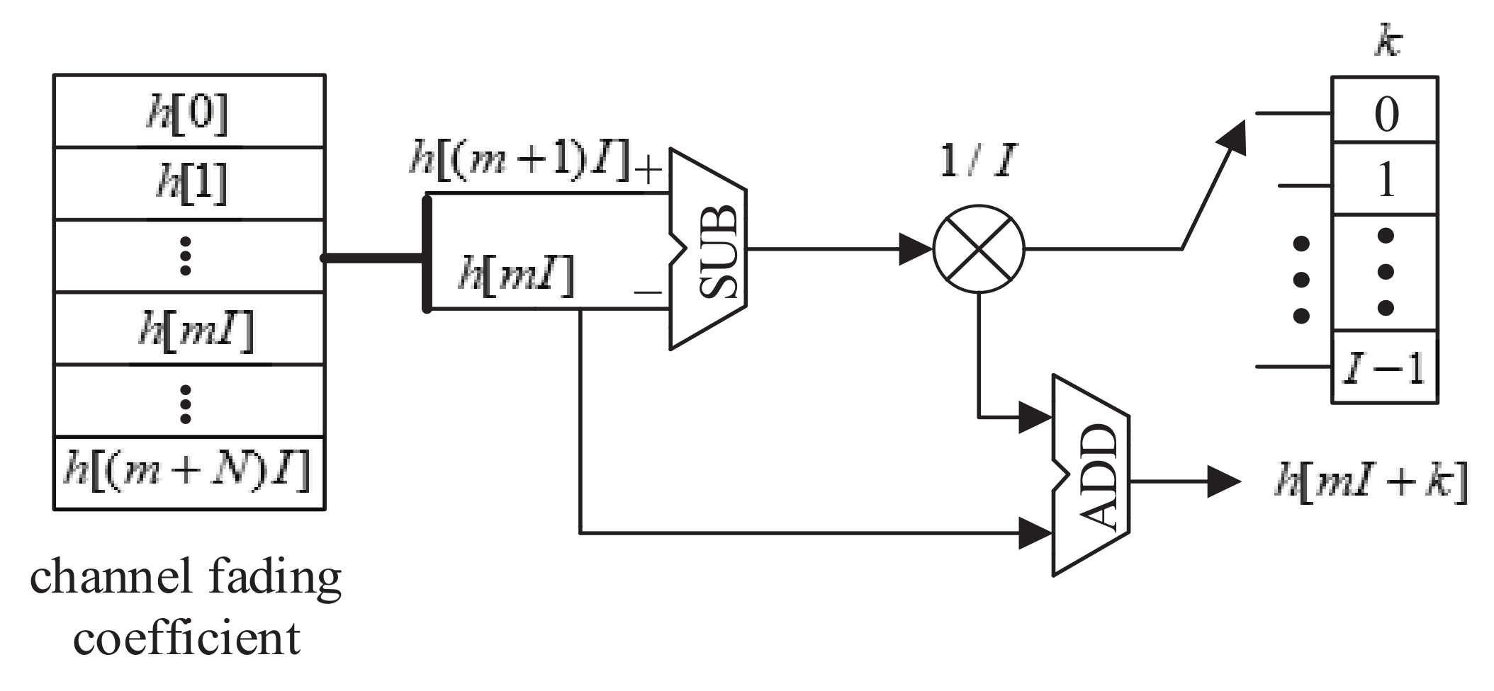
3.3.3. Interpolator Module

The interpolator module performs a linear interpolation by I times to match the data rate between the channel fading and the input signal. The channel sampling rate f s is much smaller than the system sampling rate f s , so the channel fading rate should be interpolated to f s = I × f s . Let us denote two adjacent channel fading samples as h [ m I ] and h [ ( m + 1 ) I ] , then the linear interpolation can be realized as
h [ ( m I + k ) ] = ( h [ ( m + 1 ) I ] h [ m I ] ) k I + h [ m I ]
where k = 0 , 1 , I 1 . The scheme of interpolator module in this paper includes one SUB, one multiplier, and one ADD shown in Figure 7. In this figure, two input ports of subtractor represent the adjacent channel fading samples, and the difference value is multiplied by the weight coefficient k / I . Finally, the output of multiplier and the first channel fading sample are summed up by an adder to obtain the interpolated channel fading sample.

4. Resource Consumption and Measurements

4.1. Resource Consumption

In this section, we take a 2 × 2 MIMO channel as an example to be implemented in one FPGA chip (Virtex-7). It should be noted that a single path generation needs 64 sub-paths or FM signals as shown in (5). Thus, for a single channel with M multiple paths, the traditional parallel method theoretically needs to prestore 128 × M cosine tables. In this paper, we implement the channel fading module by adopting a serial scheme or time division idea as shown in Figure 6, which only needs 2 × M cosine tables. Table 1 compares the hardware resources usages of a 2 × 2 MIMO channel emulator in [22] and a 2 × 2 MIMO channel emulator generated by the proposed method. It shows that the proposed method is more efficient than the one in [22]. The selected FPGA (Xilinx XC7VX690TFFG1927-2) consists of about 433,200 Slice LUTs, 1470 Block RAMs, and 3600 digital signal processors (DSPs). Considering the resource consumption of other modules and the efficiency of FPGA layout, it can be estimated that a 32 × 32 MIMO channel can be emulated on this single chip.

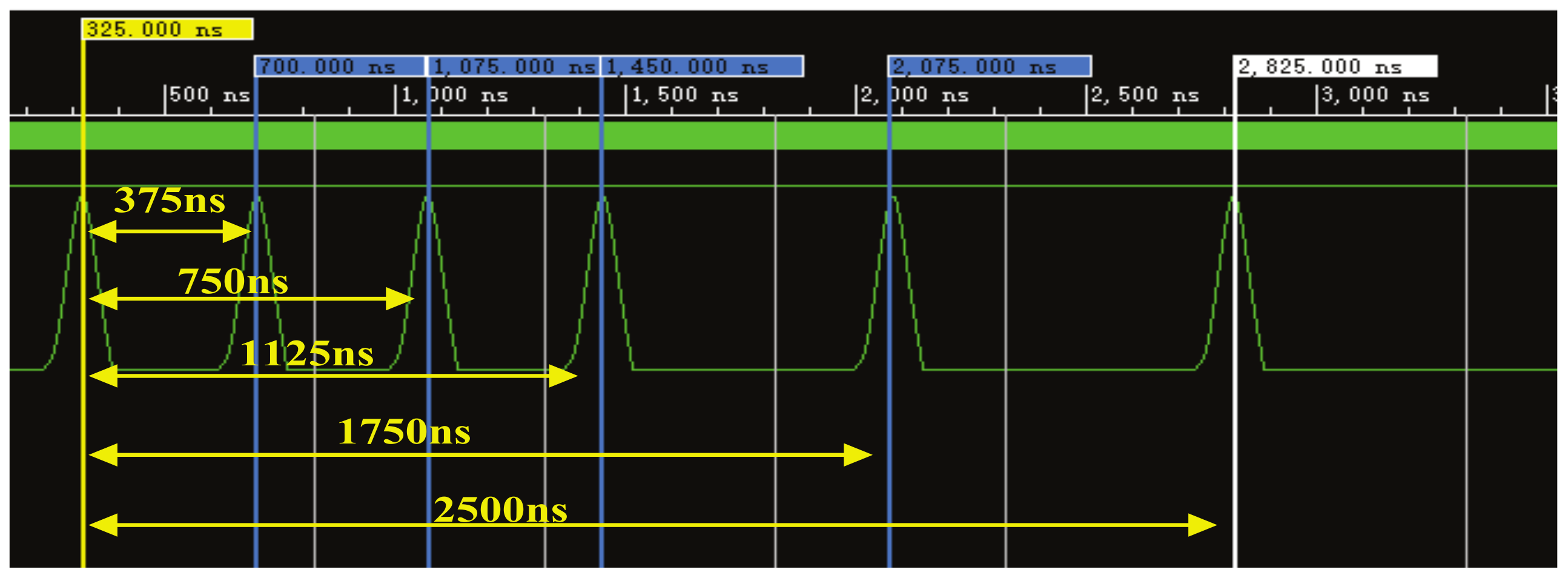
4.2. Measured Results and Analysis

In order to verify the output channel of proposed emulator, we consider that both of the base station (BS) and MS are equipped with normalized omnidirectional antennas, the carrier frequency is f c = 2.4 GHz , and the scatterers are randomly distributed around the BS and MS. The number of paths and sub-paths are six and sixty-four, respectively, i.e., N = 6 , M = 64 . Moreover, all these six paths are assumed to be valid over the simulation period. The initial distance between the BS and MS is 318 m. The absolute speed, azimuth angle, and elevation angle of the moving MS are 40 km/h, 10 ° 8 ° · t , and 10 ° 0.1 ° · t , respectively. Other emulation parameters are as follows, T u = 25 ms , L = 10 .
Based on the parameter calculation method of GBSM in [27], we can obtain the theoretical time-variant PDP under the above scenario as shown in Figure 8a. As we can see, as the MS has an initial distance of 318 m from the BS, the initial time delay of line-of-sight (LOS) path equals to 318 / ( 3 × 10 8 ) = 1.06 × 10 6 s . The time delay of non-line-of-sight (NLOS) paths can also be calculated and shown in Figure 8a with the dotted line. By using the ILA software, we store and export the data from the hardware emulator, and then analyze the data with Matlab. Finally, the measured time-variant PDP of emulator is given in Figure 8b, which clearly shows that it is consistent well with the theoretical one.
Under the same condition, the time-variant DPSD is also tested and verified. With the help of (22) in [27], the theoretical time-variant DPSD is firstly calculated and shown in Figure 9a. For comparison purposes, we also give the simulated time-variant DPSD based on the model in [17] in Figure 9b. It is clearly showed that the part around circles is different from the theoretical one. The main reason is the output Doppler phase of that model is discontinuous which results in the output Doppler frequency or DPSD not accurate. In order to observe the output DPSD directly, a 2.4 GHz cosine signal generated by a Agilent E4438C is adopted as the input signal. Then, the measured DPSD of proposed emulator can be obtained by a spectrum analyzer of ROHDE&SCHWARZ FSV. The measured result is shown in Figure 9c. Due to the randomness and distortion caused by the fixed point process, the measured result can only be qualitatively compared with the theoretical one. Figure 9a,c show that the shape and trend of two DPSDs have a good approximation, which also validates the effectiveness of proposed emulator.
Without loss of generality, only the fading envelope PDF of first NLOS path for the first sub-channel is tested and validated. First, the theoretical time-variant PDF of channel fading is derived and shown in Figure 10a. It is apparently showed that the PDF changes over time due to the time-variant channel conditions. Similarly, with the help of Xilinx software development tool, we export the data of output fading envelope from the hardware, and then analyze the distribution by Matlab. Figure 10b gives the measured PDFs at three different time instants t = 0 s , 4 s , and 8 s . For comparison purpose, the corresponding theoretical results are also extracted from Figure 10a and showed in Figure 10b, which also fit well with the measured ones. In addition, we configure the channel parameters by referring to [31] as follow. The height of BS is 30 m, and the initial distance between the MS and BS is 90 m. The MS is moving towards the BS at a speed of 10 m per second. By using the similar method as above, we can obtain the measured PDF as shown in Figure 10c. It is shown that the measured PDF of proposed channel emulator is close to the result of field test in [31].
Based on the theoretical expressions of (28)–(30) in [32] and (9)–(10) in [33], the absolute values of time-variant CCF of firt two paths are calculated and given in Figure 11. In the figure, we assume that the antenna spaces of the BS and MS are the same, and equal to twice the wavelength of carrier. Then, the measured CCF of proposed emulator can be obtained in a similar way as mentioned above and given in Figure 11 for comparison purpose. As can be seen from the figure, the CCF changes over time due to the movement of the MS. Again, the measured CCF aligns well with the theoretical one, proving the correctness of output correlation properties.

5. Conclusions

This paper has proposed a discrete non-stationary MIMO channel model, which is suitable to realize on the FPGA-based platform. A tailored hardware architecture of channel emulator with flexible size and parameters has also been developed. In addition, the hardware implementation of key modules have been illustrated in details and applied in a single FPGA chip. Finally, the PDP and other statistical properties of proposed channel emulator have been tested. The measured results have shown that the output PDP, DPSD, PDF, and CCF are consistent well with the corresponding theoretical ones. Therefore, the proposed non-stationary channel emulator can be applied to evaluate and validate the performance of MIMO communication devices in the future.

Author Contributions

Conceptualization, Q.Z. and W.H.; methodology, Q.Z. and K.M.; software, Z.Z.; validation, W.H. and Z.Z.; writing—original draft preparation, Q.Z. and W.H.; writing—review and editing, all authors; supervision, W.Z. and B.H. All authors have read and agreed to the published version of the manuscript.

Funding

This work was supported in part by the Fundamental Research Funds for the Central Universities (No. NS2020026 and No. NS2020063), in part by the Aeronautical Science Foundation of China (No. 201901052001), and in part by the National Key Scientific Instrument and Equipment Development Project under Grant (No. 61827801).

Conflicts of Interest

The authors declare no conflict of interest.

References

  1. Agiwal, M.; Roy, A.; Saxena, N. Next generation 5G wireless networks: A comprehensive survey. Commun. Surv. 2016, 18, 1617–1655. [Google Scholar] [CrossRef]
  2. Wang, C.X.; Bian, J.; Sun, J. A survey of 5G channel measurements and models. Commun. Surv. 2018, 20, 3142–3168. [Google Scholar] [CrossRef]
  3. Zhang, J.; Shafi, M.; Molisch, A.F.; Tufvesson, F.; Wu, S.; Kitao, K. Channel models and measurements for 5G. IEEE Commun. Mag. 2018, 56, 12–13. [Google Scholar] [CrossRef]
  4. Kamga, G.; Xia, M.; Aissa, S. Channel modeling and capacity analysis of large MIMO in real propagation environments. In Proceedings of the IEEE International Conference on Communications, London, UK, 8–12 June 2015; pp. 1447–1452. [Google Scholar]
  5. Li, J.; Jiang, D.; Zhang, X. DOA estimation based on combined unitary ESPRIT for coprime MIMO radar. IEEE Commun. Lett. 2017, 21, 96–99. [Google Scholar] [CrossRef]
  6. Fan, W.; Carton, I.; Kyosti, P.; Karstensen, A.; Jamsa, T.; Gustafsson, M.; Pedersen, G. A step toward 5G in 2020: Low-cost OTA performance evaluation of massive MIMO base stations. IEEE Antennas Propag. Mag. 2017, 59, 38–47. [Google Scholar] [CrossRef]
  7. N5106A PXB Channel Emulator. Available online: https://www.keysight.com (accessed on 13 June 2020).
  8. Azimuth ACE 400WB Channel Emulator. Available online: https://cdn.thomasnet.com (accessed on 13 June 2020).
  9. Ghiaasi, G.; Ashury, M.; Vlastaras, D.; Hofer, M.; Xu, Z.; Zemen, T. Real-time vehicular channel emulator for future conformance tests of wireless ITS modems. In Proceedings of the 2016 10th European Conference on Antennas and Propagation (EuCAP), Davos, Switzerland, 10–15 April 2016; pp. 1–5. [Google Scholar]
  10. Fard, S.F.; Alimohammad, A.; Cockburn, B.F. Single-field programmable gate array simulator for geometric multiple-input multiple-output fading channel models. IET Commun. 2011, 5, 1246–1254. [Google Scholar] [CrossRef]
  11. Huang, P.; Du, Y.; Li, Y. Stability analysis and hardware resource optimization in channel emulator design. IEEE Trans. Circ. Syst. 2016, 63, 1089–1100. [Google Scholar] [CrossRef]
  12. Alimohammad, A.; Fard, S.F. A compact architecture for simulation of spatial-temporally correlated MIMO fading channels. IEEE Trans. Circ. Syst. 2014, 61, 1089–1100. [Google Scholar]
  13. Dahech, W.; Patzold, M.; Gutierrez, C.A.; Youssef, N. A nonstationary mobile-to-mobile channel model allowing for velocity and trajectory variations of the mobile stations. IEEE Trans. Wirel. Commun. 2017, 16, 1987–2000. [Google Scholar] [CrossRef]
  14. Liang, X.; Zhao, X.; Li, Y.; Wang, Q. A non-stationary geometry-based street scattering model for vehicle-to-vehicle wideband MIMO channels. IEEE Wirel. Commun. 2016, 90, 325–338. [Google Scholar] [CrossRef]
  15. Zhu, Q.; Li, W.; Yang, Y.; Xu, D. A general 3D nonstationary vehicle-to-vehicle channel model allowing 3D arbitrary trajectory and 3D-shaped antenna array. Int. J. Antennas Propag. 2019, 2019, 8708762. [Google Scholar] [CrossRef] [Green Version]
  16. Ghazal, A.; Wang, C.X.; Ai, B.; Yuan, D.F.; Hass, H. A nonstationary wideband MIMO channel model for high-mobility intelligent transportation systems. IEEE Trans. Intell. Transp. Syst. 2015, 16, 885–897. [Google Scholar] [CrossRef] [Green Version]
  17. Ghazal, A.; Yuan, Y.; Wang, C.X. A non-stationary IMT-advanced MIMO channel model for high-mobility wireless communication systems. IEEE Trans. Wirel. Commun. 2016, 16, 2057–2068. [Google Scholar] [CrossRef] [Green Version]
  18. Zhu, Q.; Wang, Y.; Jiang, K.; Chen, X.; Zhong, W.; Ahmed, N. 3D non-stationary geometry-based MIMO channel model for UAV-Ground communication systems. IET Microw. Antennas Propag. 2019, 13, 1104–1112. [Google Scholar] [CrossRef]
  19. Ren, F.; Zheng, Y.R. A novel emulator for discrete-time MIMO triply selective fading channels. IEEE Trans. Circ. Syst. 2010, 57, 2542–2551. [Google Scholar] [CrossRef]
  20. Habib, B.; Zaharia, G.; Zein, G.E. Hardware Simulator for MIMO Propagation Channels: Time Domain Versus Frequency Domain Architectures. Sci. J. Circ. Syst. Signal Proc. 2013, 2, 37–55. [Google Scholar] [CrossRef]
  21. Habib, B.; Zaharia, G.; Zein, G.E. MIMO hardware simulator design for outdoor time-varying heterogeneous channels. In Proceedings of the International Symposium on Signals, Circuits and Systems, Lasi, Romania, 11–12 July 2013; pp. 1–4. [Google Scholar]
  22. Zhang, N.; Yang, G.; Zhai, J. Design and implementation of flexible 4M × 4N MIMO channel emulator. In Proceedings of the IEEE Antennas and Propagation Society International Symposium, Memphis, TN, USA, 6–11 July 2014; pp. 713–714. [Google Scholar]
  23. Tien, T.V.; Tien, T.M.; Khai, L.D. Hardware Implementation of a MIMO Channel Emulator for high speed WLAN 802.11 ac. In Proceedings of the 2018 5th NAFOSTED Conference on Information and Computer Science, Ho Chi Minh City, Vietnam, 23–24 November 2018; pp. 183–188. [Google Scholar]
  24. Habib, B.; Baz, B. Digital architecture of 8 × 8 MIMO Hardware channel simulator for time-varying heterogeneous systems with LTE-A, 802.11 ac and VLC signals. In Proceedings of the 2016 3rd International Conference on Advances in Computational Tools for Engineering Applications (ACTEA), Beirut, Lebanon, 13–15 July 2016; pp. 195–200. [Google Scholar]
  25. Hofer, M.; Xu, Z.; Vlastaras, D.; Schrenk, B.; Tufvesson, F.; Zemen, T. Real-time geometry-based wireless channel emulation. IEEE Trans. Veh. Technol. 2019, 68, 1631–1645. [Google Scholar] [CrossRef]
  26. Ruiz, A.E.; Gutierrez, C.A.; Castillo, J.V.; Cortez, J. SDR-Based channel emulator for vehicular communications. In Proceedings of the 2019 IEEE Colombian Conference on Communication and Computing (COLCOM), Barranquilla, Colombia, 5–7 June 2019; pp. 1–6. [Google Scholar]
  27. Zhu, Q.; Li, H.; Fu, Y.; Wang, C.X.; Tan, Y.; Chen, X. A novel 3D non-stationary wireless MIMO channel simulator and hardware emulator. IEEE Trans. Commun. 2018, 66, 3865–3878. [Google Scholar] [CrossRef]
  28. Zhu, Q.; Liu, X.; Yin, X.; Chen, X.; Xue, C. A novel simulator of nonstationary random MIMO channels in Rayleigh fading scenarios. Int. J. Antennas Propag. 2016, 2016, 3492591. [Google Scholar] [CrossRef] [Green Version]
  29. Nguyen, T.T.; Lanante, L.; Nagao, Y.; Kurosaki, M.; Ochi, H. MU-MIMO channel emulator with automatic channel sounding feedback for IEEE 802.11 ac. In Proceedings of the Wireless Communications and Networking Conference, Doha, Qatar, 3–6 April 2016; pp. 1–6. [Google Scholar]
  30. Hua, J.; Yang, J.; Lu, W.; Meng, L.; Yu, X. Design of universal wireless channel generator accounting for the 3-D scatter distribution and hardware output. IEEE Trans. Instrum. Meas. 2014, 64, 2–13. [Google Scholar] [CrossRef]
  31. Qiu, Z.; Chu, X.; Calvo-Ramirezand, C.; Briso-Rodriguez, C.; Yin, X. Low Altitude UAV Air-to-Ground Channel Measurement and Modeling in Semiurban Environments. Wirel. Commun. Mob. Comput. 2017, 2017, 1587412. [Google Scholar] [CrossRef] [Green Version]
  32. Jiang, K.; Chen, X.; Zhu, Q.; Chen, L.; Xu, D.; Chen, B. A Novel Simulation Model for Nonstationary Rice Fading Channels. Wirel. Commun. Mob. Comput. 2018, 2018, 8086073. [Google Scholar] [CrossRef] [Green Version]
  33. Zhu, Q.; Yang, Y.; Wang, C.X.; Tan, Y.; Sun, J.; Chen, X.; Zhong, W. Spatial correlations of a 3-D nonstationary MIMO channel model with 3-D antenna arrays and 3-D arbitrary trajectories. IEEE Wirel. Commun. Lett. 2019, 8, 512–515. [Google Scholar] [CrossRef]
Figure 1. System architecture of the proposed emulator.
Applsci 10 04161 g001
Figure 2. Sum-of-frequency-modulated-signals (SoFM)-based channel fading generator.
Applsci 10 04161 g002
Figure 3. The implementation scheme of delay module.
Applsci 10 04161 g003
Figure 4. Hardware simulation of delay module.
Applsci 10 04161 g004
Figure 5. The implementation scheme of channel fading module.
Applsci 10 04161 g005
Figure 6. Hardware simulation of channel fading module.
Applsci 10 04161 g006
Figure 7. The implementation scheme of interpolation module.
Applsci 10 04161 g007
Figure 8. (a) The theoretical results of time-variant power delay profile (PDP) and (b) the measured time-variant PDP of proposed emulator.
Applsci 10 04161 g008
Figure 9. (a) The theoretical results of time-variant Doppler power spectrum density (DPSD), (b) the simulated time-variant DPSD of the model in [17], and (c) the measured time-variant DPSD of proposed emulator.
Applsci 10 04161 g009
Figure 10. (a) The theoretical results of time-variant PDFs, (b) the measured time-variant PDFs of proposed emulator at different time instants, and (c) the measured PDF of proposed emulator and the PDF of field test.
Applsci 10 04161 g010
Figure 11. The absolute values of the theoretical and measured cross-correlation functions (CCFs).
Applsci 10 04161 g011
Table 1. Hardware resource usage of a 2 × 2 MIMO channel emulator.
The Method in [22]The Proposed Method
System sample rate100 M256 M
Slice LUTs152,33725,800
Block RAMs191116
DSPs768160

