Abstract
Electric vehicles usage and adoption have expanded rapidly over the last decade, as the global energy demand is shifting away from fossil fuels. The recent development of electric vehicle charging technology, which is a fast charging mode, enables an electric vehicle to be fully charged within 10 minutes. However, the generated harmonics, control complexity, and cost of fast charging are the main challenges that need to be addressed to further expand the electric vehicle fast charging technologies. In this manuscript, a new electric vehicle fast charger was designed by introducing the three-stage converters based on the integration between internal model controller with synchronized decoupled controller algorithms. The proposed charger can provide two types of charging approaches, namely alternating current (AC) fast charging and direct current (DC) fast charging. To verify the effectiveness of the proposed charger, the model is developed and simulated in MATLAB/Simulink 2018a platform. Additionally, experimental verification, which utilizes a digital signal processor (TMS320F28335), is conducted to further support the design concept and the simulation findings. These research results have indicated that the proposed charger is applicable for fast AC and DC charging. Moreover, the total harmonic distortion value for the input current is 1.55%, where it has constantly been maintained within the standard limits, thus showing the effectiveness of proposed charger in performing the charging process without causing any significant impact to the grid.
1. Introduction
The transportation sector has the prime share in the global average per capita energy consumption. This condition raises concerns about the carbon emission and energy independency due to the reliance on fossil fuel. Substituting internal combustion engine (ICE) vehicles, which are powered by gasoline or diesel, by electric vehicles (EVs) is a potential approach to solve the environmental issues and energy crisis. Consequently, various countries have taken the initiatives to develop their own EV manufacturing, aiming to de-carbonize their transportation sectors. An EV battery can be charged by using either direct current (DC)charging technologies (known as off-board charging) or alternating current (AC) charging technologies (known as on-board charging) [1]. Recently, a number of advanced approaches have been applied to EV charging. These approaches can be categorized into three groups namely, slow charging (up to 10 kW), fast charging (up to 24 kW), and quick charging (50 kW or higher) [2]. The main challenge of slow charging is that it takes a longer time to fully charge the battery, typically around 8 to 12 h.
Nowadays, an EV with lithium-ion battery is sustainable for 100 kilometers range, where the battery could be fully charged within 30 min by using a fast charging approach. In this respect, a real implementation of EVs fast charging station equipped with an energy storage system is briefly presented in [3], where multiple EV charging stations with AC distribution network has been analyzed accordingly. In order to decrease the high energy demanded from the grid for EV fast charging, a renewable energy can be installed in the charging stations [4]. The modeling of a high-power density, efficient, and reliable fast charging has become a major challenge of expanding the number of EVs globally. In other words, one of the main issues with EV fast charging is the usage of power electronics devices; such as rectifiers, inverters, and converters that potentially generate harmonics distortion into the electricity grid. These harmonics have a major impact on the stability and power quality of the electricity grid. In addition, the charging currents and voltages with high total harmonic distortion (THD) can eventually damage other electrical and electronic devices around the charger station, such as conductors and transformers [5]. Recently, the THD that are generated through an EV charging process is standardized by IEC 1000-3-2 and SAE J2894/1 standards, where these standards are highlight the limit of THD allowed by EV charging [6].
One of the commonly used approach to eliminate these harmonics distortion is by using a passive filter, where this approach provides a low impedance path to the harmonics currents Several researchers generally utilized passive filter in order to reduce THD of EV fast charging stations [7,8,9], and most typical ones is a single tuned filter. The single tuned filter is designed to mitigate a specific harmonic component from the charging system by a properly sized inductance, capacitance, and resistance values [10]. The authors in [11] proposed a band-pass inductor–capacitor (LC) filter integrated into an asymmetric synchronous reference of an EV charger connected to the grid to mitigate the 5th and 7th harmonic components. However, there is a lack of research in measuring both voltage and current harmonics in EV fast charging.
Previous researchers have designed active power filters (APFs) in EV fast charging to decrease the harmonic distortions created by the nonlinear components. AFPs can be classified into two types, namely, shunt active power filter and series active power filter. Shunt APFs are more conventionally used compared to series APFs in the EV fast charging stations. Shunt APFs have several advantages, such as easy installation and capable of improving the power factor by decreasing the reactive power drain on the distribution network [6]. The researchers in [12], developed a fast battery charger with shunt APF to improve the power factor correction and to decrease the THD by imposing the utility to supply the active current. However, the current approaches cannot regulate the charging precisely due to the fact that the interface between the harmonic current and harmonic voltage of the charging station is not considered, and an accurate approach of choosing the safety factor has not been proposed.
Recently, multiple control algorithms have been developed in the EV fast charging system in order to reduce the THD in power distribution networks, such as direct power control (DPC) [13], hysteresis control [14,15], and model predictive control (MPC) [16]. However, one of the main disadvantages of these algorithms is the capability to observe the harmonic distortion limits of specific order harmonic frequencies, (10k ± 1, 8k ± 1 6k ± 1, 4k ± 1; for k = 1, 2, ...) of the output voltages/currents.
In order to address these gaps, this paper proposes a novel technique of designing and developing an EV fast charger with integrated internal model controller (IMC), where the proposed design provides high dynamic operation and low THD of the drawn currents/ voltages. Besides, the developed IMC has superior control performance compared with an existing current control method. In this respect, the developed IMC controller is structurally simple and can be executed by proportional integral (PI) and proportional integral derivative (PID) controllers. The isolation mechanism is provided between the grid and vehicle through a three-phase transformer integrated with the charger system. The proposed controller demonstrates a low THD of the input current with almost unity power factor. Moreover, this EV charger is capable to perform two types of EV charging, where it provides three-phase AC and DC fast charging, as shown in Figure 1. In this paper, IMC with decoupled controllers are integrated to control three-stage converters of the EV fast charger.
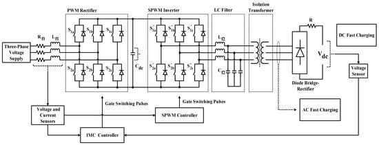
Figure 1.
Overall structure of the proposed electric vehicle (EV) fast charger.
The core contributions of this research are as follows:
- This work is designed to provide two approaches of fast charging, as it can deliver DC and AC fast charging.
- The proposed EV fast charger is designed in a significant method that reduces the overall weight and size of the charger.
- The proposed EV fast charger is more adaptable in different scenarios, specifically where there are restrictions in resources or space.
This manuscript is organized as follows. In Section 2, the method of IMC with synchronized decoupled controller is briefly described. Section 3 presents the simulation structure of the proposed EV fast charger by using MATLAB/Simulink 2018a software, and the simulation results are discussed as well. Section 4 describes the prototype setup of the proposed EV fast charger with its experimental results. Outcomes verification and comparison are presented in Section 5. Finally, in Section 6, the conclusion highlights the significant contributions of this research.
2. IMC with Synchronized Decoupled Controller
This section introduces the novel design of EV fast charging (DC and AC fast charging) based on IMC with decoupling between active and reactive components, where feedforward decoupled controller has been modeled and combined with pulse width modulation (PWM) scheme to generate six pulse signals of each converter. The DC-link voltage controller and current controllers have been modeled by applying IMC technique, which requires coordinate transformation (Clarke and Park transformation), followed by decoupling between active and reactive components.
In the first step, the input line voltage of the charger needs to be supplied to the input of the phase-locked loop (PLL). Secondly, the voltage angle (θ) is calculated in the PLL scheme to be used in three-phase (abc) to dq-coordinate transformation of line current and voltage. In the third step, the dq-coordinate values (i.e., ) with the DC-link voltage value ( are supplied into the decoupled controller based on three synchronized PI controllers. Finally, the reference voltages which are transformed to three-phase abc coordinate, are sent to the PWM scheme to generate the switching patterns , as shown in Figure 2.
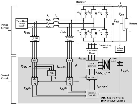
Figure 2.
Block diagram of internal model controller (IMC) with synchronized decoupled controller.
2.1. Implementation of IMC with Three-Stages Converters
This stage is considered the most significant part of the charger, where it is linked to the main functions of IMC with decoupled controller process. The overall structure of multiple mode fast charger consists of three stages of power conversion controlled by IMC with decoupling between active and reactive components, as shown in Figure 3. Three-phase bridge rectifier (PWM rectifier) is placed in the first stage of the power conversion followed by the DC-link capacitor. The current and voltage controllers are utilized by getting the feedback voltage from the EV battery as a part of closed loop operation control.
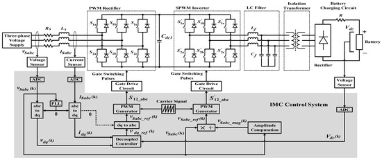
Figure 3.
IMC with synchronize decoupled controllers integrated to three stage of the proposed EV charger.
The output of DC-Link capacitor is connected to the three-phase inverter (SPWM inverter), which is controlled by SPWM switching technique, followed by a three-phase transformer, which is used between the AC fast charger (first mode charging) and EV connectors. Besides the isolation between the charger and the EVs, the main purpose of this transformer is to step-up or step-down the voltage based on the technologies of EVs. Passive filter (LC filter), is connected to the output of the SPWM in order to meet the standard charging distortion limits. Finally, a diode bridge rectifier is connected to the primary side of the transformer to provide DC fast charger (second mode charging).
2.2. Integration of PLL into Clarke and Park Transformation
In this EV fast charging system, the PLL is considered as a critical and important part, where it is designed to detect the phase angle (θ) of the utility voltages (. This phase angle is then used for all dq-transformations in the charging system, as shown in Figure 4. The process of IMC is primarily executed in the synchronous reference frame (dq0) and alpha–beta transformation (αβ0), using Clarke and Park transformation matrices using Equations (1) to (4). These transformation matrices are applied to the model charging system as shown in Equations (5) to (6):
where , and are input voltages in three-phase frame, , , , , and are the source voltages in and frames, as shown in Figure 5.
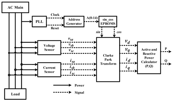
Figure 4.
Block configuration phase-locked loop (PLL) combined with Clarke and Park transform.
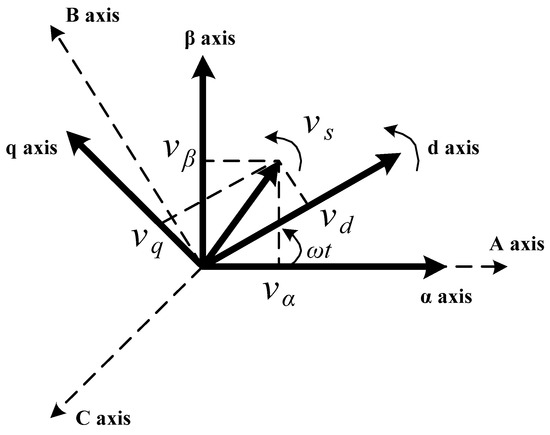
Figure 5.
Phasor diagram of Clarke and Park transformation.
2.3. Synchronized PI Controllers of IMC
Clarke and Park transformation matrices are applied to convert AC signals to DC signals in the controlled part. In this case, steady-state errors are minimized by the PI controllers which are based on the following equations:
where and are the reference signals of and in units of Amps., respectively, which are obtained from the measured DC voltage of PWM rectifier, while and are the gains of PI controller, and and are the current source in frame. The reference voltages and in unit of Volt are transformed using inverse Clarke and Park transformation to derive gate switching pulses which controls the operation of PWM rectifier, as shown in Equation (9).
The DC-link voltage control is used to regulate the active current component ( in unit of Amp to obtain active power that flows during the charging process. The value of reactive components () is set to zero in unit of Amp., to achieve unity power factor and to mitigate the THD.
The proposed approach uses three PI controllers (one voltage controller and two current controllers). The output loop of DC-link voltage ( in unit of Volt is regulated by PI voltage controller, the measured (V) with its pre-determined reference value are compared to estimate the reference current signal . The first current controller is used to regulate the inner loop of current component by minimizing the error between with in order to estimate the reference voltage signal . Likewise, the second PI current controller is used to regulate the second inner loop of current component, where its is set to zero to estimate the reference voltage signal . As illustrated in Figure 6, the characteristic of three PI controllers are given as follow:
where in PI voltage controller, and represent the gain values of the proportional and integral gains, respectively, while in the first PI current controller, and in represent the gain values of the proportional and integral gains, respectively, finally in the second PI controller, and represent the gain values of the proportional and integral gains, respectively. The bandwidth is chosen to be smaller than a decade below the switching frequency () in inner current control loops in Hz [17], as follows:
where (rad/s) is the bandwidth.
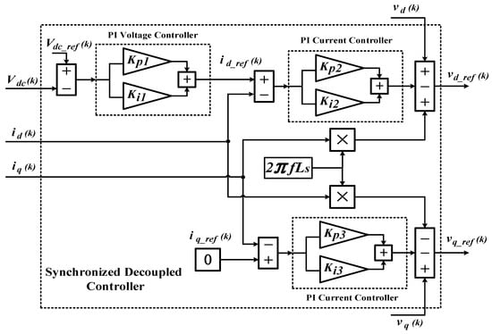
Figure 6.
The block diagram of synchronized decoupled controller with three proportional integral (PI) controllers.
The DC link capacitor, which is located in the voltage control loop, is used to tune the PI controller as follow [17]:
where is the angular frequency in (rad/s), and ς is the damping factor, which is fixed at 0.707.
2.4. Modulation Process of PWM Rectifier and SPWM Inverter
The modulation technique is operated by comparing two signals; sinusoidal modulating signal which is considered as a low-frequency signal and triangular carrier signal which is considered as a high-frequency signal. The intersection of these signals generates pulses with varying duty cycles. In this work, three balanced-sinusoidal controlled voltages are compared with their respective triangular voltage waveforms, where the output of these intersections is applied to control the switching function of the switching components in each leg of the converter. The switching frequency applied for the SPWM technique is set to 12 kHz. The value of switching frequency is set to 12 kHz. The switching devices are functioning in a complementary manner in each phase: When the upper leg is in the open position, the lower leg will be in the closed position, and vice versa.
2.5. Configuration Parameters
The main configuration parameters of the developed controller include the input source parameters, PWM rectifier, PI controllers, and SPWM inverter. In this regard, the input source parameters refer to the three-phase input voltage supply ( and three-phase input voltage supply (, where the frequency of these inputs is 50 Hz. In addition, inductors of 5 mH and resistors ( of 5 Ω are considered as the input filter of the charger, which is connected to the input of the next part of the charger (PWM rectifier). This rectifier consists of six switches of insulated-gate bipolar transistor (IGBT) transistors connected to and DC-link capacitor, where the output of this capacitor connected to the three-phase inverter (SWPM inverter). This inverter consists of six switches of IGBT transistors, where the output of each phase is connected at the middle of each inverter leg. The output of the comparators provides the gating pulses required for controlling the switching operation of all three legs in the inverter. The switching frequency applied for the PWM is set at 12 kHz. The charging process is performed by three PI controllers to control the input current and output voltage.
3. Simulation Work of EV Fast Charger
In this work, the MATLAB/Simulink 2018a software was used to model and simulate the proposed EV fast charger. The SimPower System, which is the common toolbox to simulate the power electronic circuits, is used to design and simulate the three stages of power conversion along with the control system of the EV fast charger.
3.1. Simulation Setup
The actual and optimum values of the Simulink components are determined by considering the values of IMC model along with synchonized decoupled controller. As illustrated in Figure 7, the simulation components of the charger consist of three-phase supply, PWM rectifier, SPWM inverter, three-phase transformer, LC filter, diode bridge rectifier and battery. The values of the simulation parameters used include grid frequency 50 Hz, input inductor filter 5 mH, and switching frequency 12 kHz. The simulation work has been done with discrete parameters since the digital signal processors (DSP) works only with discrete parameters to ensure there is no problem when the simulation work is uploaded to DSP.
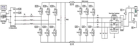
Figure 7.
The simulation circuit of EV fast charger.
3.2. Simulation Results and Discussions
The findings obtained from the simulation work are clearly presented and thoroughly discussed in this section. Figure 8 shows the voltage and current waveforms of EV fast charging system, where Figure 8a,b present the simulation waveforms of the drawn voltage and current from the grid to the charging station, respectively. According to these figures, the three-phase input current have a nearly sinusoidal wave shape (with low THD) which is working in phase with the three-phase input voltage (unity power factor). Figure 8c,d show the three-phase voltage waveforms of AC fast charging (first mode charging), where Figure 8c illustrates the output voltage of the SPWM inverter before the LC filter, while Figure 8d shows the charging voltage which is delivered to the primary side of the transformer.
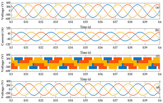
Figure 8.
Simulation waveforms of the drawn voltage and current from the grid to charging station: (a) input three-phase voltages, (b) input three-phase currents, (c) three-phase voltage waveforms of AC fast charging before LC filter, (d) three-phase voltage waveforms of AC fast charging after LC filter.
Figure 9 depicts the waveforms of input currents (phase A, phase B, and phase C) correspondingly with three-phase input voltages in Figure 9a. Based on the observation of these waveforms, the input current of phase A, phase B, and phase C are kept in synchronized phase shift with the three-phase input voltages .
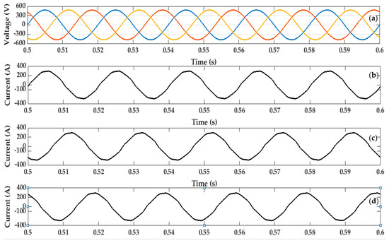
Figure 9.
The waveforms of three-phase input voltages along with input currents: (a) input three-phase voltages, (b) input current (phase A), (c) input current (phase B), (d) input current (phase C).
Figure 10 presents phase A waveforms of AC fast charging voltage and current. According to Figure 10a,b, the fast charging system is operated in unity power factor during the entire charging as the input current of phase A is kept in phase with the input voltage of phase A. The unity power factor is obtained since the reactive component (iq), inside IMC process, is regulated to zero. Figure 10c,d show the voltage waveforms of AC fast charging (first mode charging) for phase A, while Figure 10c illustrates the output voltage of the SPWM inverter before the LC filter, while Figure 10d shows the charging voltage which is delivered to the primary side of the transformer.
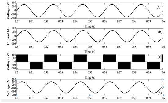
Figure 10.
Phase A waveforms of AC fast charging voltage and current: (a) input voltage, (b) input current, (c) voltage before LC filter (d) voltage after LC filter.
Figure 11 illustrates the current and voltage waveforms of DC fast charging (second mode charging). In order to perform the DC fast charging (second mode charging), it can be perceived that the proposed EV fast charger was able to maintain the output DC charging of current 130 A along with the output DC charging voltage of 650 V.
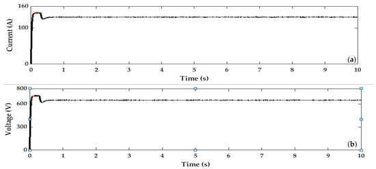
Figure 11.
The current and voltage waveforms of DC fast charging: (a) current, (b) voltage.
Figure 12 shows the THD result of the input current of phase A, where this result was obtained by using the fast Fourier transform (FFT) analysis with a fundamental frequency of 50 Hz. As can be observed from this figure, it is clear that the proposed control scheme is able to maintain the THD of the input current at 1.55% while performing the DC and AC charging, thus leading to unity power factor of the fast charging system. Moreover, the proposed EV fast charger is proven to provide effective DC and AC charging without causing any noticeable harmonic distortion to the connected grid.
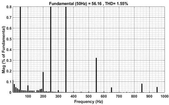
Figure 12.
Total harmonic distortion (THD) result of the input current of Phase A.
Table 1 compares the performance of the proposed charger with the existing chargers in term of the control structure, mitigation the THD, and isolation system. As presented in Table 1, the proposed charger, which is controlled by IMC with synchronized decoupled controller algorithms, provides potential advantages by considering controller complexity and THD performance. In addition, the integration of a three-phase transformer in the proposed charger performs an isolation mechanism between the grid and vehicle.

Table 1.
The performance of the proposed charger compared with existing chargers.
4. Experimental Setup
The next step is verifying the performance of the IMC with synchronized decoupled controller, by implementing a hardware prototype of the charger. This prototype has been built with the same component values in the modeling design of the charger, as shown in Figure 13. The PI compensator gains are also the same as those in the analysis and simulations. The digital signal processor (DSP- Texas Instruments TMS320F28335) functions act as a brain for the three-stage converters, where all the input and output signals are processed inside the DSP. In addition, all of the signals used by the PWM rectifier and SWPM inverter are processed through DSP.
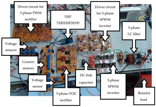
Figure 13.
Prototype implementation of EV fast charger.
4.1. Prototype Implementation
Experimental validation is performed to provide experimental proof of the proposed EV fast charging system. The procedure prototype implementation is explained by the flowchart structure, as shown in Figure 14. Based on this figure, the input voltages and currents have been measured to be used to generate a synchronized PLL. The laboratory prototype is implemented with similar design parameters as applied in the simulation model. Nevertheless, for safety purposes and due to limitation of resources, the input voltage is scaled down to 120 V. A TMS320F28335 DSP is configured and programmed to perform all the control algorithms, and to generate gate pulses to both the PWM rectifier and SPWM inverter.
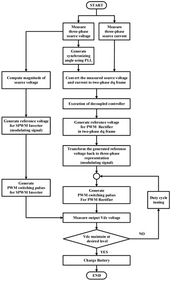
Figure 14.
The procedure of implementation the EV fast charging prototype.
4.2. Experimental Results and Discussions
The findings obtained from the experimental work are clearly presented and thoroughly discussed in this section. Figure 15 shows the measurement results for the three-phase input voltages and current based on the prototype of EV fast charging. According to Figure 15a,b, it can be seen that the voltage and current waveforms are shifted by 120° and the natural aspect of the waveforms is sinusoidal. Figure 15c shows the three-phase voltage waveforms of AC fast charging (first mode charging). This figure presents three voltage waveforms; PWM reference voltage ( of phase A, output voltage of phase A for the SPWM inverter before LC filter, and output voltage of phase to phase (phase A to phase B) for the SPWM inverter before the LC filter.
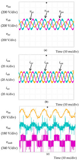
Figure 15.
Measurement results of the three-phase input voltages and current: (a) input three-phase voltages, (b) input three-phase currents (c) three-phase voltage waveforms of AC fast charging.
According to Figure 16a, the input AC current of phase A works in the same phase with the input AC voltage to ensure the unity power factor of the charger. Figure 16b shows the measurement result for the three-phase input currents (phase C, phase B, and phase A) of fast charging. It can be seen that the current is shifted by 120° sequence of three-phase and the natural aspect of the waves has no distortion.
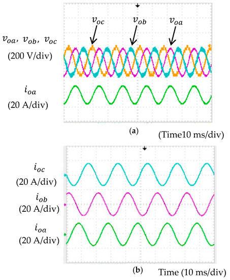
Figure 16.
The measurements waveforms of three-phase input voltages along with input currents: (a) input three-phase voltage with input current of phase (A), (b) input current phase (A), input current (B), and current phase (C).
It can be observed in Figure 17, the input voltage and current waveforms for phase A and C exhibit sinusoidal wave shape. Moreover, the output DC voltage is observed to be continuously maintained at a fixed value with a constant DC output voltage.
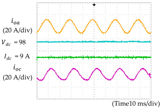
Figure 17.
The current and voltage measurements waveforms of DC fast charging.
Figure 18 shows the THD of phase A input current for the EV fast charger, obtained under medium power test. From the findings, the THD of input current is effectively maintained below 5 %, which complies with IEEE standard 519-2014.
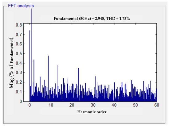
Figure 18.
Measurements THD result of the input current of Phase A.
5. Verification and Comparison of Simulation and Experimental Results
This section describes the verification of the simulated results with experimental results. From both simulation and experimental works, by using the proposed IMC decoupled controller algorithms, the fast charging system is able to provide constant charging voltage and current charging. Besides, it can be clearly seen that the output DC fast charging voltage has a low ripple. Moreover, from both simulation and experimental results, the input current waveform is observed to be sinusoidal with minimum distortion (low THD value), and is working in phase with the input voltage, thus achieving almost unity power factor.
However, THD value of the input current to the charger from the experimental work (1.75%) is found to be higher than the simulated value (1.55%). One of the reasons could be due to the power losses in the experimental work that were not considered in the simulation. In addition, in experimental work, due to resource limitations, the maximum input supply voltage for the battery charger was set to 100 Vrms (line to line). Whereas in simulation setup, the reference voltage is set to 650 V. Further, in the experimental work, the charging system is operated at a much lower current value compared to the simulation work. In the experimental work, the maximum input supply voltage for the battery charger is set to be 200 V, while in simulation work the maximum input supply voltage for the battery charger is set to be 480 V. Therefore, the results that were captured from the experimental work are found to be different than the simulated value. Since the magnitude of the fundamental current is low, thus a higher THD value is recorded from the experimental work.
6. Conclusions
In this work, the proposed EV fast charger designed based on the integrated IMC with synchronized decoupled control for DC and AC fast charging is fabricated and tested in lab environment. This paper brings out the methodology of this research. First, the principles of the proposed control method of the converter which is IMC with synchronized decoupled controller algorithm is explained. Secondly, the simulation is carried out using MATLAB/Simulink software. Finally, the implementation of the experimental setup in laboratory is carried out to verify the proposed design. From both simulation and experimental work, the proposed IMC with synchronized decoupled controller algorithms used in the fast charging system is able to provide constant voltage and current charging. Besides, it also can be clearly seen that the output DC charging voltage has a low ripple. Moreover, from both simulation and experimental results, the input current waveform is observed to be sinusoidal with minimum distortion (low THD value), and is working in phase with the input voltage, thus achieving almost unity power factor, where the reactive component is set to zero. In addition, IMC with synchronized decoupled controller accurately regulates the output DC voltage. It is clear that the control algorithm accurately regulates the output DC voltage. Besides, it ensures a sinusoidal input current with minimum switching ripples and distortions. The power factor of the system is almost unity, and THD for the input current is less than 1.55%.
Author Contributions
A.S.A.-O. designed, developed and implemented the control for this research. He also verified the design via simulation, and experimental setup. He analyzed the results and was also mainly responsible for manuscript preparation I.B.A. supervised the simulation and experimental work as the supervisor of the project and also contributed in the manuscript preparation. A.R. contributed in analyzing and verifying the results and in manuscript preparation. T.J.T.H., M.B.M. and A.H.S. were in charge in verifying the work and have actively contributed in finalizing the manuscript. All authors have read and agreed to the published version of the manuscript.
Funding
This research was funded by, Universiti Tenaga Nasional (UNITEN) BOLD Grant, UNITEN BOLD Publication Fund for publication and Universiti Putra Malaysis (UPM) Research Grant number: RUGS 05-02-12-1881RU for research work expenditure.
Conflicts of Interest
The authors declare no potential conflict of interest.
References
- González, L.G.; Siavichay, E.; Espinoza, J.L. Impact of EV fast charging stations on the power distribution network of a Latin American intermediate city. Renew. Sustain. Energy Rev. 2019, 107, 309–318. [Google Scholar] [CrossRef]
- Aziz, M.; Oda, T.; Ito, M. Battery-assisted charging system for simultaneous charging of electric vehicles. Energy 2016, 100, 82–90. [Google Scholar] [CrossRef]
- Sbordone, D.; Bertini, I.; Di Pietra, B.; Falvo, M.C.; Genovese, A.; Martirano, L. EV fast charging stations and energy storage technologies: A real implementation in the smart micro grid paradigm. Electr. Power Syst. Res. 2015, 120, 96–108. [Google Scholar] [CrossRef]
- Domínguez-Navarro, J.A.; Dufo-López, R.; Yusta-Loyo, J.M.; Artal-Sevil, J.S.; Bernal-Agustín, J.L. Design of an electric vehicle fast-charging station with integration of renewable energy and storage systems. Int. J. Electr. Power Energy Syst. 2019, 105, 46–58. [Google Scholar] [CrossRef]
- Al-Ogaili, A.S.; Hashim, T.J.T.; Rahmat, N.A.; Ramasamy, A.K.; Marsadek, M.B.; Faisal, M.; Hannan, M.A. Review on Scheduling, Clustering, and Forecasting Strategies for Controlling Electric Vehicle Charging: Challenges and Recommendations. IEEE Access 2019, 7, 128353–128371. [Google Scholar] [CrossRef]
- Zhou, N.; Wang, J.; Wang, Q.; Wei, N.; Lou, X. Capacity calculation of shunt active power filters for electric vehicle charging stations based on harmonic parameter estimation and analytical modeling. Energies 2014, 7, 5425–5443. [Google Scholar] [CrossRef]
- Shafad, K.H.; Jamian, J.J.; Nasir, S.A.S. Harmonic distortion mitigation for multiple modes charging station via optimum passive filter design. In Proceedings of the 2016 IEEE Conference on Systems, Process and Control, (ICSPC ’16), Melaka, Malaysia, 16–18 December 2016; pp. 219–223. [Google Scholar]
- Nguyen, V.L.; Tran-Quoc, T.; Bacha, S. Harmonic distortion mitigation for electric vehicle fast charging systems. In Proceedings of the IEEE Grenoble Conference, Grenoble, France, 16–20 June 2013; pp. 1–6. [Google Scholar]
- Hao, C.C.; Tang, Y.J.; Shi, J. Study on the harmonic impact of large scale electric vehicles to grid. AMM Appl. Mech. Mater. 2013, 443, 273–278. [Google Scholar] [CrossRef]
- Cho, Y.; Cha, H. Single-tuned passive harmonic filter design considering variances of tuning and quality factor. J. Int. Counc. Electr. Eng. 2011, 1, 7–13. [Google Scholar] [CrossRef]
- Farkoush, S.; Kim, C.; Rhee, S. THD reduction of distribution system based on ASRFC and HVC method for SVC under EV charger condition for power factor improvement. Symmetry 2016, 8, 156. [Google Scholar] [CrossRef]
- Kuperman, A.; Levy, U.; Goren, J.; Zafranski, A.; Savernin, A. Modeling and control of the PFC stage for a 50 kW EV fast battery charger. In Proceedings of the World Congress on Engineering 2011, London, UK, 6–8 July 2011; Volume 2, pp. 5–9. [Google Scholar]
- Zhang, Y.; Qu, C. Model predictive direct power control of PWM rectifiers under unbalanced network conditions. IEEE Trans. Ind. Electron. 2015, 62, 4011–4022. [Google Scholar] [CrossRef]
- Hiskens, I. Achieving controllability of electric loads. Proc. IEEE 2011, 99, 184–199. [Google Scholar]
- Callaway, D. Tapping the energy storage potential in electric loads to deliver load following and regulation, with application to wind energy. Energy Convers. Manag. 2009, 50, 1389–1400. [Google Scholar] [CrossRef]
- Rodriguez, J.; Pontt, J.; Silva, C.; Correa, P.; Lezana, P.; Cortes, P.; Ammann, U. Predictive current control of a voltage source inverter. IEEE Trans. Ind. Electron. 2007, 54, 495–503. [Google Scholar] [CrossRef]
- Al-Ogaili, A.S.; Aris, I.B.; Verayiah, R.; Ramasamy, A.; Marsadek, M.; Rahmat, N.A.; Hoon, Y.; Aljanad, A.; Al-Masri, A.N. A three-level universal electric vehicle charger based on voltage-oriented control and pulse-width modulation. Energies 2019, 12, 2375. [Google Scholar] [CrossRef]
- Jackson, D.; Schultz, A.; Leeb, S.B.; Mitwalli, A.; Verghese, G.; Shaw, S.R. A multirate digital controller for a 1.5-kW electric vehicle battery charger. IEEE Trans. Power Electron. 1997, 12, 1000–1006. [Google Scholar] [CrossRef]
- Fasugba, M.A.; Krein, P.T. Gaining vehicle-to-grid benefits with unidirectional electric and plug-in hybrid vehicle chargers. In Proceedings of the IEEE Vehicle Power and Propulsion Conference, Chicago, IL, USA, 6–9 September 2011. [Google Scholar]


© 2020 by the authors. Licensee MDPI, Basel, Switzerland. This article is an open access article distributed under the terms and conditions of the Creative Commons Attribution (CC BY) license (http://creativecommons.org/licenses/by/4.0/).