Article

Study of the Mechanism of a Stable Deposited Height During GMAW-Based Additive Manufacturing

1
The State Key Laboratory of Fluid Power and Mechatronic Systems, College of Mechanical Engineering, Zhejiang University, Hangzhou 310058, China
2
Polytechnic Institute, Zhejiang University, Hangzhou 310015, China
*
Author to whom correspondence should be addressed.
Appl. Sci. 2020, 10(12), 4322; https://doi.org/10.3390/app10124322
Submission received: 19 May 2020 / Revised: 14 June 2020 / Accepted: 17 June 2020 / Published: 24 June 2020

Abstract

:
Gas metal arc welding (GMAW)-based additive manufacturing has the advantages of a high deposition rate, low cost, the production of a compact and dense microstructure in the cladding layer, and good mechanical properties, but the forming process is unstable. The shape of the welding bead critically affects the layer height and dimensional accuracy of the parts manufactured, and it is difficult to control. A series of experiments were designed and the results indicated that when the value of the predefined layer height is set in a certain range and other parameters are held constant, the height of the thin wall produced by GMAW-based additive manufacturing is almost equal to the predefined layer height multiplied by the number of layers. This research work shows that during the GMAW process, the changes in the distance between the torch and the top surface of the part cause a variety of dry extensions of the electrode; furthermore, the changes lead to a variety in the heat input into the molten pool. Therefore, the dry extension of the electrode is the key factor influencing the geometry of the welding bead, especially the layer height, and it has a compensating effect that makes the actual layer height close to the predefined value. A three-dimensional numerical model was established to study the influence of the predefined layer height to the fluid flow and heat transfer behaviors during the weld-deposition process.

1. Introduction

Additive manufacturing technology, is a novel technology for making complex parts layer by layer. There are several additive manufacturing approaches, such as directed light fabrication (DLF), laser-based additive manufacturing (LBAM), rapid direct metal deposition, selective laser sintering (SLS), and electron beam free forming (EBF) [1]. Compared with other methods, gas metal arc welding (GMAW)-based additive manufacturing has shown great potential due to several advantages, including high productivity, low cost, and a strong bonding strength of the parts [2].
During the multilayer deposition process of GMAW-based additive manufacturing, either the substrate moves to a low position or the torch rises to a high position with a predefined distance after the welding of a layer finished. The critical issue is that the height of the deposited bead is not always equal to the predefined layer height. The reason can be attributed to a slight change in the manufacturing parameters, such as arc current and voltage as well as deposition rate, and the GMAW process is sensitive to these parameters. Furthermore, the geometry of the layer is related to changes in the heat dissipation of the different layers, interlayer temperatures, the distance between the nozzle and the top surface of the parts, and the geometry and initial temperature of the substrate [3].
Furthermore, the accumulated error in the layer height increases as the multilayer deposition process continues. In other words, the distance between the nozzle and the top surface of the part is inevitably changeable. It is well known that a long distance makes the arc unstable, reduces gas protective effects, and leads to poor quality or formation of the layer. Conversely, a short distance causes welding spatters to adhere to the nozzle and the top surface of the parts even contact the nozzle. These two situations make the GMAW-based wire and arc additive manufacturing process unstable.
Xiong et al. [4] developed a new method by integrating plasma arc deposition and the milling technology to improve the processing quality of the parts. Xiong et al. [5] used a neural network and a second-order regression analysis for predicting bead geometry; they then developed a passive vision sensor system to monitor the nozzle to the top surface distance, and the deviations in thedistance are compensated by the movement of the substrate [3]. However, an increased productivity is desirable in manufacturing processes. The disadvantage of the approach of combining plasma arc deposition and milling techniques is that the process time and cost are increased. The method of adding a passive vision sensor system increases the facilities cost.
Panchagnula et al. [6] built a mathematical model that uses the values of the height and width of the first layer to predict the geometries of other layers. In addition, the model predicts the relationship between the geometry of bead and key process parameters [7].
The deposited height is probably affected by the integrated transport phenomenon in the molten pool. To revel this mechanism, it is necessary to make a comprehensive description of molten pool dynamics. The computational fluid dynamics (CFD) method can be used to simulated the situation in the molten pool. Zhou et al. [8] developed a three-dimensional weak-coupling modeling method for the arc and metal transport to simulate the arc, the molten pool dynamics, and the droplet impingement during arc welding-based additive manufacturing.
This paper combines experiments with numerical simulation, and these experiments include producing thin walls with different parameters using GMAW-based additive manufacturing. The results of the experiments show that when keeping other manufacturing parameters constant, the total height of the thin wall produced by GMAW-based additive manufacturing is almost equal to the predefined layer height multiplied by the number of layers if the value of the predefined layer height changes in a certain range. The dry extension of the electrode is the key factor that influences the layer height; it has a compensating effect that makes the actual layer height close to the predefined value. Since it is difficult to measure the conditions of a molten pool due to conditions such as the fluid flow and heat transfer behaviors, a three-dimensional numerical model is established with the temperature-dependent material properties. In this study, the changes in the molten pool due to various dry extensions of the electrode are the primary aspects of interest.

2. Experimental Details

2.1. Experimental Conditions

The objective of the present research is to develop a system by combing a welding station and an industrial robot which provides processing freedom. As shown in Figure 1, the industrial robot is a COMAU SMART 5 NJ60-2.2, which can realize multiple degrees of freedom during manufacturing and can transfer the component from one position to another. The welding system is a KEMPPI A7 MIG welder. A temperature measuring device is mounted under the substrate to ensure that the temperature of the substrate is held constant at the beginning of every experiment. The software control process is running on a Beckhoff industrial computer, which communicates between the robot and the welding system.
During the experiments, the torch is stationary, and the robot moves the substrate near the torch. The KEMPPI A7 MIG welder provides a “wise thin+” procedure in which the output welding voltage and current are based on the wire feeding speed. The temperature of the substrate remains the same as the ambient temperature during the experiments.
Ogino et al. [9] found that when the cooling time is set appropriately, the deposition shape increases in height and decreases in thickness. If the welding direction is reversed for each layer, the variance of the deposition height becomes small; if the welding direction does not change for each layer, the height becomes uneven, and the starting point is higher than the ending point. The experiments build thin walls comprising 100 layers with different parameters, and the direction is changed after each layer is finished to keep the height of the thin wall uniform. The wire feed speed is 3.0 m/min, travel speed is 0.011 m/s, welding voltage and current are set by a wise thin+ procedure based on the wire feed speed, interval time between two layers is 5 s, and the initial dry extension of the electrode is 12 mm.

2.2. Materials

The materials selected for the welding experiments are as follows: 18 mm thick stainless steel substrate, 1.2 mm diameter stainless steel welding wire, and 98% Ar–2% O2, which was used as the shielding gas, with a gas flow of 20 L/min. The initial nozzle-to-substrate distance is 12 mm, and the dry extension of the electrode is also 12 mm.

2.3. Results of Experiments

Table 1 lists the influence of the predefined layer height (PLH) on the total height and width of thin walls comprising 100 layers. If the total height of the thin wall comprising 100 layers is equal to the substrate moving distance (SMD), it can be assumed that the distance between the torch and the substrate or the top surface of the thin wall is constant. From Figure 2, we see that when the predefined layer height is 0.85 mm, it is similar to the mean height of the thin wall, and this value represents the ideal situation; the rate of accumulated error is less than 0.15%. As a result, the dry extension of the electrode and the effect of the shielding gas are nearly constant. If the predefined layer height is not equal to 0.85 mm, the mean height of the thin wall varies between the predefined layer height and the ideal layer height of 0.85 mm.
The values of the predefined layer height lead to different distances between the torch and the substrate or the top surface of the thin wall. Specifically, the distance consists of two parts: the dry extension of the electrode and the arc length. To study how the predefined layer height affects the total height of thin walls comprising 100 layers, it is necessary to determine the factors decided by the dry extension of the electrode and the length. If the dry extension of the electrode is constant, the arc length has the same change as the distance. It alters the arc pressure, the Lorentz force, the radiation and convective heat transfer between the torch and molten pool surface. The arc pressure and Lorentz force decrease as the arc length becomes longer, and the conditions of heat dissipation improve. As a result, the height of the bead increases and the width decreases. While the arc length decreases, arc pressure and Lorentz force increase, and the heat dissipation decreases, so the height of the bead decreases and the width increases. However, if the arc length remains constant, the dry extension of the electrode changes with distance, and the forces acting on the molten pool do not change.
To find the relationship between the shape of the bead and the dry extension of the electrode, the experiments focused on using various dry extensions of the electrode to weld only one layer at a time. From Figure 3, the welding bead with an electrode dry extension of 12 mm is lower and wider than the welding bead with an electrode dry extension of 20 mm. From Figure 4, the mean arc power, mean welding current, and the voltage all decrease while the initial dry extension of the electrode increases. The heat input into the molten pool depends on the mean arc power; as the initial dry extension of the electrode increases, the heat input into the molten pool also decreases. Figure 5 shows the shape of the bead, which only welds a layer on the substrate with different initial dry extensions of the electrode. The dry extension of the electrode changes over time during the welding process. As the initial dry extension of the electrode increases, the shape of the bead will increase in height and decrease in width. When the welding of every bead was complete, the dry extension of the electrode reduced by a length that is equivalent to the height of the bead plus nearly 1 mm. From the experimental data, it can be inferred that the dry extension of the electrode has a greater variation than the arc length, while the distance between the torch and substrate or the top surface of the thin wall changes.
The key factors that determine the shape of the welding bead are the heat input into the molten pool and the heat dissipation conditions. In the process of building thin walls comprising 100 layers using 0.85 mm as the predefined layer height, the first layer bead is the highest because its heat dissipation condition is the best due to the temperature of the substrate being equal to the ambient temperature. The dry extension of the electrode is also longest for the first layer bead. When the first bead completes, the dry extension of the electrode decreases in length, and the heat input into the molten pool during welding the second layer increases. Thus, the height of the second layer decreases and the width increases compared to those of the first layer. As the welding process continues, the temperature of the substrate stabilizes. When welding a certain layer, the heat dissipation condition does not change; the actual layer height is nearly equal to the predefined layer height, and the dry extension of the electrode remains constant. This is the ideal situation; if the actual layer height changes on a small scale, the dry extension of the electrode changes when welding the next layer, which can compensate for the error in the height of the previous layer. In other words, if the height of this layer decreases, the dry extension of the electrode will increase when welding the next layer, so the heat input into the molten pool decreases. The height of the next layer increases, and as a result, the height of the thin wall increases nearly uniformly. Figure 6 shows the thin walls manufactured with different values of the predefined layer height, the total height of the thin wall increases while raising the PLH.
The manufacturing parameters of the GMAW-based multilayer deposition process include the welding speed, wire feed speed, welding current and voltage, predefined layer height, shield gas flow rate, and the temperature of the substrate and ambient. When other parameters are held constant, there is a predefined layer height that can ensure the total height of the thin wall equals the predefined layer height, which represents the distance that the substrate moved along the negative z direction during the building process multiplied by the number of layers. The predefined layer height is called the ideal height for the corresponding set of parameters. Figure 7 shows that the effective welding speed is greater than the effective wire feed speed. When the wire feed speed remains constant, the ideal height decreases while the welding speed increases.

3. Process Simulation

To determine how the distance from the nozzle to the top surface influences the geometry of the welding bead, a three-dimensional numerical model is established with temperature-dependent material properties because it is difficult to measure the molten pool conditions, such as the fluid flow and heat transfer behaviors. In this study, changes in the molten pool due to various dry extensions of the electrode are the primary aspects of interest.
Flow 3D software was used for this work to simulate the welding of the first layer on the substrate with various distances from the nozzle to the top surface. The software used a grid of rectangular cells to discretize the physical space, and finite difference methods were applied to solve the governing equations. The volume of fluid (VOF) approach was used by Flow 3D to describe the free surface of the fluid and the boundary conditions at this surface [10].

3.1. Mathematical Models

A three-dimensional numerical model was developed to investigate the heat and mass transfer in the molten pool of the GMAW-based additive manufacturing processes. The governing equations were solved using the Flow 3D code. The liquid metal was considered to be a Newtonian and incompressible fluid. The heat and mass loss caused by the liquid metal vaporization was ignored. The droplets were modeled as a source term that carried mass, momentum, and energy in the computational domain.

3.2. Governing Equations

The geometry model of the computational domain is shown in Figure 8. The GMAW welding pools were modeled using a 3D Cartesian coordinate system, and the governing equations are the mass, momentum, and energy equations. The VOF method was used to track the dynamic gas–metal interface, the free surface of the molten pool, and the solidified bead. Initially, the bottom part was filled with metal and represented the substrate. The thickness of the substrate was 15 mm, and the initial temperature was equal to the environmental temperature of 300 K. The following governing equations were calculated in the whole domain [11]:
·   V   = R S O R ρ
V t + ( V · ) V = 1 ρ P h + μ 2 V + f + R S O R ρ · V K V
ρ ( h t + ( V · ) h ) = ( κ T ) + R I S O R
F t + ( V · F ) = F s
To express the convection of the volume fraction in the fraction in the fluid flow at the welding pool, an additional advection relationship was employed [11]. The energy source term RISOR was calculated according to thermal structure and fluid temperature:
ρ t + ( V · ρ ) = R S O R
  ρ = ρ 0 F
R S O R = ρ 0 F s
R I S O R = h W A ( T W T )
A two-phase shielding gas and ER304 stainless steel flow model were used. In this case, the volume fraction function F = 1 corresponded to cells full of metal fluid, while F = 0 corresponded to empty cells that did not contain metal fluid. Cells with an F between 0 and 1 were located on the free surface. The gradient direction of F was the normal direction of the free surface.

3.3. Enthalpy-Temperature Relationship

The enthalpy-porosity technique was applied to model the solid–liquid mushy zone as a porous medium with porosity equal to the liquid fraction. The liquid fraction was used to implicitly track the solid–liquid interface. This technique treats the mushy zone as a porous region, and the porosity equals the liquid volume fraction fl. The liquid fraction between the solidus and liquidus points was assumed to vary linearly with temperature:
f l = { 0 T T S T L T S 1                       T T S T S < T < T L T T L
The relationship between the energy and temperature can be used to model the solid–liquid phase change. The fluid temperature in each cell can be determined from its enthalpy, and the cell becomes a part of the mushy zone if the temperature is between the liquidus and solidus temperatures. The porous media drag concept can be used to model the flow in the mushy zone [11]:
h = { ρ C p T h ( T S ) + f l H f h ( T l ) + ρ C p ( T T l )           T T S T S < T < T L T T L
A source term was added to the momentum equation to eliminate the velocities in the mushy zone and the fully solidified region.

3.4. Heat Source Model

In the gas metal arc welding process, the heat input from the arc into the molten pool is modeled as a Gaussian distribution, and the Gaussian heat distribution parameter can be calculated from the following empirical equation [11]:
q ( x , y ) = η Q 2 π σ a 2 exp ( x 2 y 2 2 σ a 2 )
σ a = 0.533 I 0.2941
In the gas metal arc welding process, even though the arc heat input also follows a Gaussian distribution, the calculated Gaussian heat distribution parameter is divided by 2 [12].

3.5. Body Forces

The body forces in the welding pool included buoyancy and the electromagnetic force. The Boussinesq approximation can be used to model the buoyancy of the liquid metal [11].
The electromagnetic force is calculated based on the current flow and the magnetic field in the welding pool [13]:
J r = σ e r ;     J z = σ e z
B θ = μ 0 r 0 r J z r d r
where ø is the scalar electric potential, which satisfies the Maxwell equation [13].

3.6. Arc Pressure

In the gas metal arc welding process, the arc pressure acting on the free surface of the welding pool can be approximated as a Gaussian density distribution [9]. The total pressure and the Gaussian pressure distribution parameter are functions of the current and the electrode tip angle:
P a r c = P 2 π σ P 2 exp ( x 2 + y 2 2 σ P 2 )
In the gas metal arc welding process, the total pressure and the Gaussian pressure distribution parameter can be expressed as the following expressions, and the calculated Gaussian pressure distribution parameter is divided by 2 [12].
σ P = 1.4043 + 0.00174 · I   ( m m )         ( 90 °   t i p   a n g l e )  

3.7. Surface Tension Force

In Flow 3D, the surface tension of the liquid metal is simplified as a linear function of temperature:
γ = γ 0 A ( T T m )

3.8. Droplet Generation

The droplets were modeled as a source term that carries mass, momentum, and energy in the computational domain. In the simulation, the droplets were defined as a spherical shape with a radius of 0.9 mm and an initial velocity of 0.05 cm/s in the negative z direction. The frequency of emerging was 18.5 drops/s, and the temperature of the droplet was set to be 1800 K. Table 2 lists the thermophysical material properties of ER304 steel used in simulation.

3.9. Boundary Conditions

The boundary conditions of the computational domain for the governing equations included energy and momentum boundary conditions.

3.9.1. Energy Boundary Conditions

For the top free surface, convection and radiation were considered:
κ T n = q ( x , y ) q c o n v q r a d
q c o n v = h c ( T T 0 )
q r a d = σ ε ( T 4 T 0 4 )
For the other surface, the following equation was used:
  κ T n = h c ( T T 0 ) σ ε ( T 4 T 0 4 )

3.9.2. Momentum Boundary Conditions

To model the Marangoni convection, the surface tension gradient on the top free surface should be equal to the shear stress:
μ u z = γ T T x
μ v z = γ T T y
For the other surface, the following equation was used:
  u = v = w = 0
The normal pressure balance of the top free surface was expressed as follows:
p + 2 μ v n n = p a r c + γ ( 1 R 1 + 1 R 2 )
Table 3 lists the explanations of parameters used in simulation.

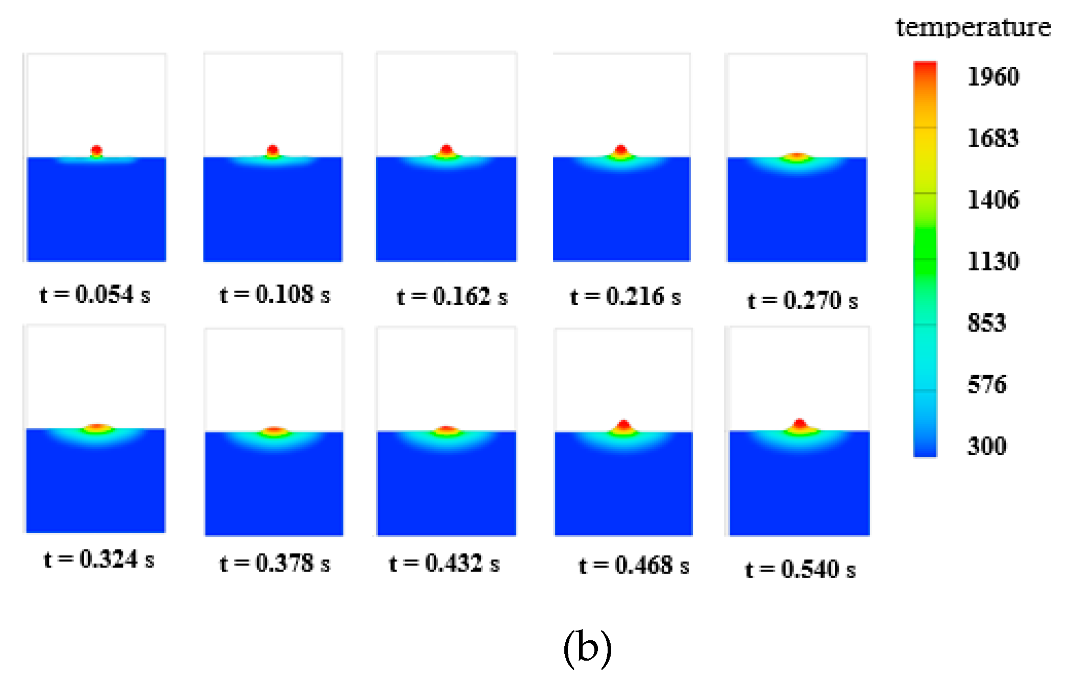
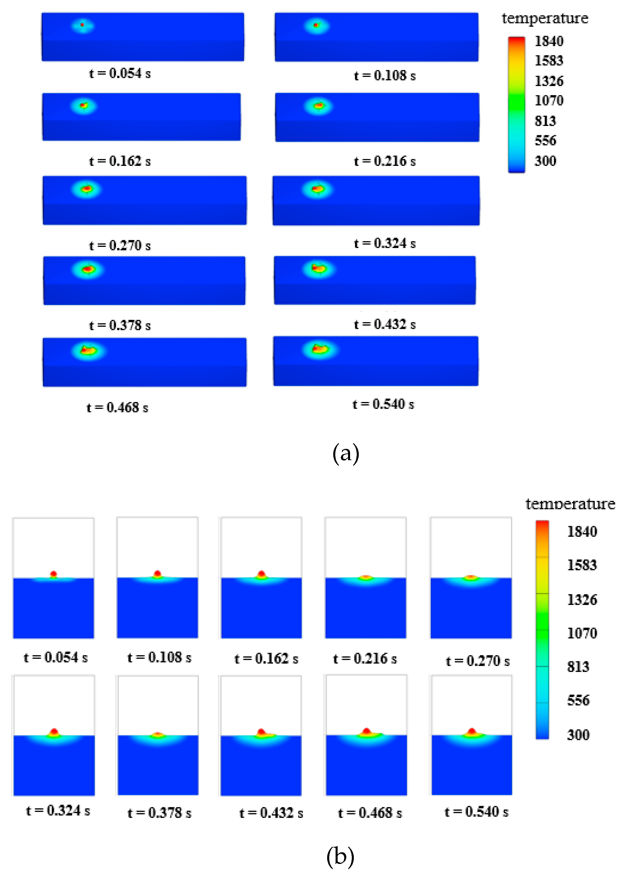
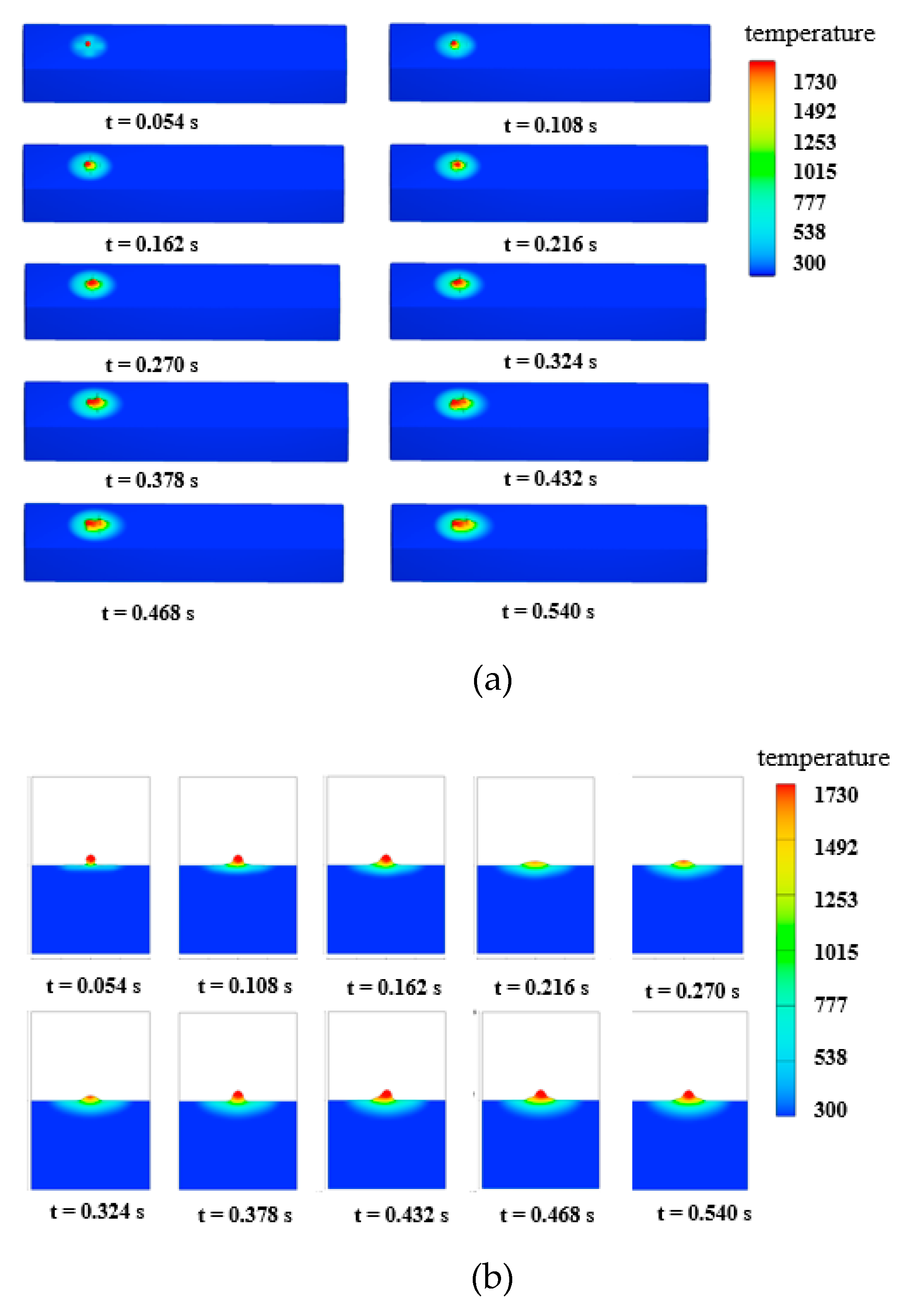
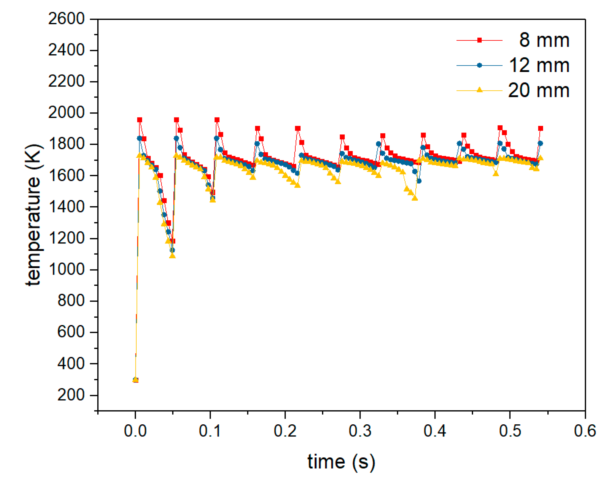
3.10. Results and Discussion

The simulations of welding on the substrate with various dry extensions of the electrode were conducted, and the detailed results were analyzed.
Under the influence of the arc heat input and the enthalpy of the droplets, the substrate begins to melt, and a welding pool forms. Wu et al. [14] found that when the welding process starts, the welding pool develops gradually as the welding time increases; at some point, the welding pool becomes stable, and the penetration, width, and welding reinforcement remain constant. Moreover, the welding process reaches a quasi-steady state.
Figure 9, Figure 10 and Figure 11 show the results with different initial values for the dry extension of the electrode; the initial temperature of the environment and substrate is 300 K. Figure 9 shows the results of the numerical simulation for the 8 mm initial dry extension of the electrode; the highest temperature in molten pool is 1960 K. Figure 10 shows the results with the initial dry extension of electrode equal to 12 mm, and Figure 11 shows it to be equal to 20mm; the highest temperatures in molten pool are 1840 K and 1730 K.
Figure 12 shows the change of the temperature at the center of the molten pool under the arc with different initial dry extensions of electrode. The temperature in the molten pool is higher with the lower initial dry extension of electrode. Therefore, if the initial dry extensions of the electrode set to be lower, the shape of the welding beads will be lower and wider; if the initial dry extensions of the electrode is set to be higher, the shape of the welding beads will be higher and narrower.
Figure 13 explains the reason that the distance between the nozzle and the top surface influences the geometry of the welding bead. When the distance decreases, the dry extension of the electrode (the stick out of length) is short; moreover, the arc power increases, and the heat input into the molten pool increases. As a result, the height of the welding bead decreases and the width increases. Conversely, if the distance increases, the height of the welding bead increases, and the width decreases. Zhao et al. [15] discovered that the diffusion of heat from the molten pool worsens as the depositing height increases. Bai et al. [16] concluded that during multilayer deposition with plasma arc welding-based wire and arc additive manufacturing, as the layer number increases, the size of the molten pool and the width of the deposited bead increase while the layer height decreases. However, when the deposited part is sufficiently high, the molten pool and the geometry of the deposited bead remain constant. In the process of building the thin walls, the initial dry extension of the electrode is 12 mm, and the heat dissipation is the best during the welding of the first layer because the temperature of the substrate is equal to the ambient temperature. When the second layer is being welded, the dry extension of the electrode is less than 12 mm, and the arc current and arc power increase, which enhances the heat input into the molten pool, arc pressure, and electromagnetic force. As a result, the heat dissipation degrades as the ambient temperature rises, and the height of the second layer is less than that of the first layer. However, when the thin wall is sufficiently high, the heat dissipation of every following layer remains constant; if the predefined layer height is almost equal to the actual height of the welding layers, the dry extension of electrode is invariant.
If the layer height is set appropriately, the dry extension of the electrode decreases at first; it then increases slightly and then remains constant. If the layer height is greater than the appropriate value, the dry extension of the electrode increases while the welding process continues, which influences the welding quality. If the layer height is less than the appropriate value, the distance between the torch and the top surface of the thin wall increases. Even if the torch touches the thin wall, the nozzle becomes damaged, and the welding process terminates. Figure 14 shows the thin wall with a predefined layer height that is larger than the ideal value; the quality of the side of the thin wall is poor. If the predefined layer height is smaller than the ideal value, the layer height changes in the range between the red curve and the line for the lower limit. As shown in Figure 15, (a) is the ideal situation, which represents the condition for the layer height being equal to the predefined value, where the dry extension of the electrode remains unchanged. The condition for the layer height being more than the predefined value is described in (b), where the dry extension of the electrode decreases during the process and leads to an increase in the arc power and heat input into the molten pool. As a result, the height of the next welding bead decreases, the width increases, and the dry extension of the electrode returns to its initial value. The layer height is less than the predefined value in (c), and the dry extension of the electrode increases during the process, which leads to a decrease in the arc power and the heat input into the molten pool. The height of the next welding bead increases and the width decreases, and then the dry extension of the electrode finally returns to its initial value.
Figure 16 shows that the manufactured vase model with a predefined layer height equals the ideal value of 0.85 mm, and the other manufacturing parameters match this value.

4. Conclusions

Based on the experimental and simulation results, the following conclusions can be drawn:
(1)
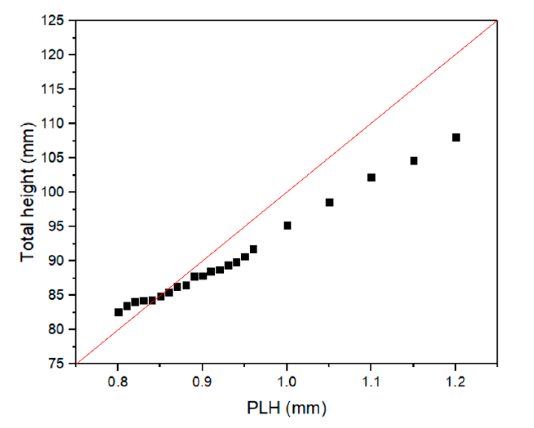
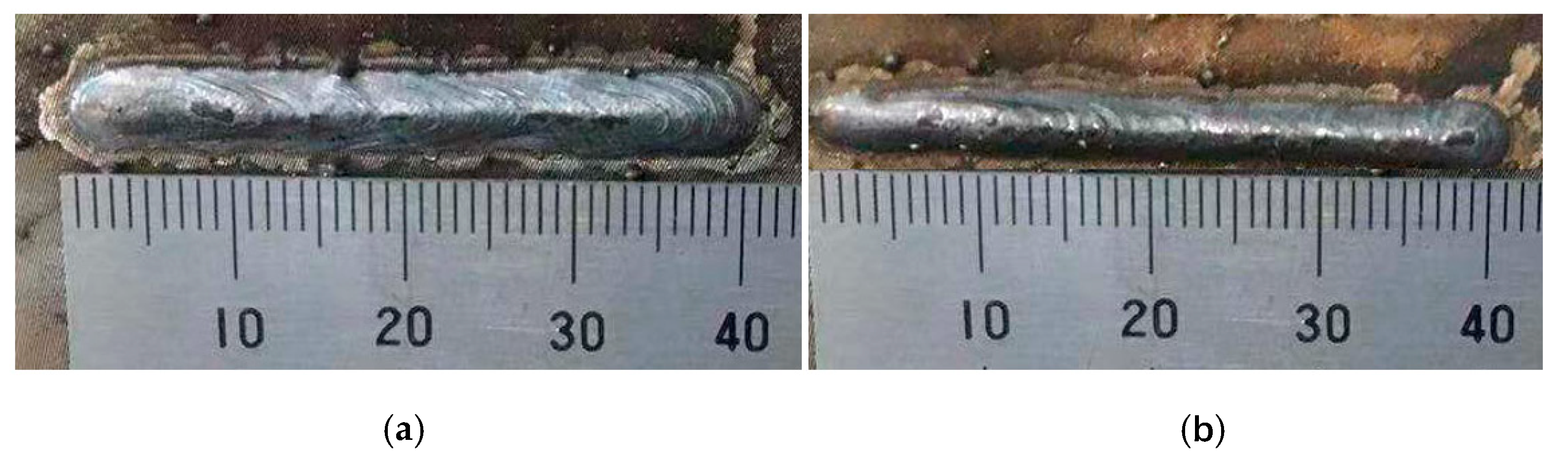
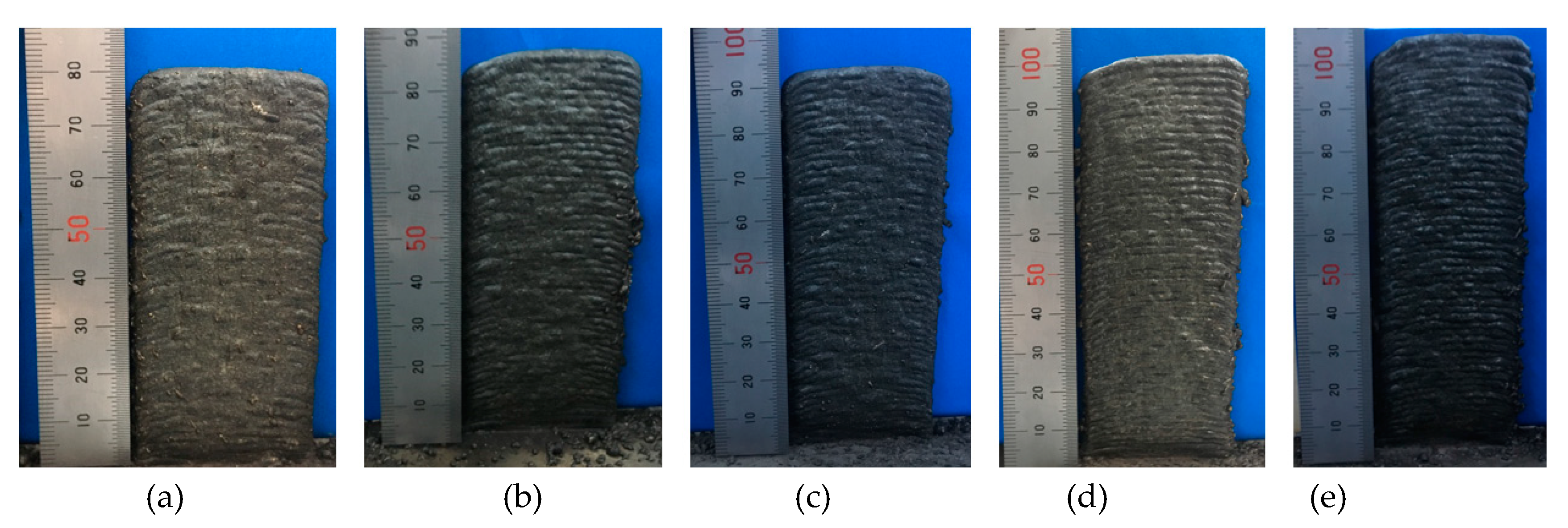
The predefined layer height influences the actual height of the welding bead during GMAW-based additive manufacturing. If the predefined layer height is set to be larger than that of the ideal value, the height of the welding bead increases, and the width decreases. Conversely, if the predefined layer height is set to be smaller, the height of welding bead decreases and the width increases.
(2)
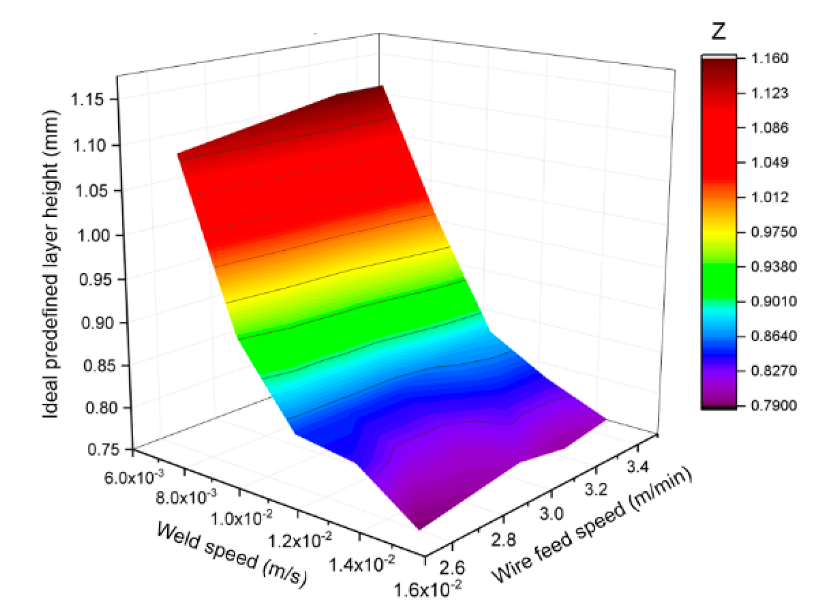
When the value of the predefined layer height changes within a certain range, other manufacturing parameters of the GMAW-based multilayer deposition process, including the welding speed, wire feed speed, welding current and voltage, shield gas flow rate, and temperature of the substrate and ambient remain constant; this situation ensures that the total height of the thin wall is almost equal to the predefined layer height multiplied by the number of layers. This ensures that the distance the substrate moved along the negative z direction during the building process is equal to the total height of the manufactured part. The welding process is continuous, and the ideal predefined layer height is almost equal to the stable deposited height.
(3)
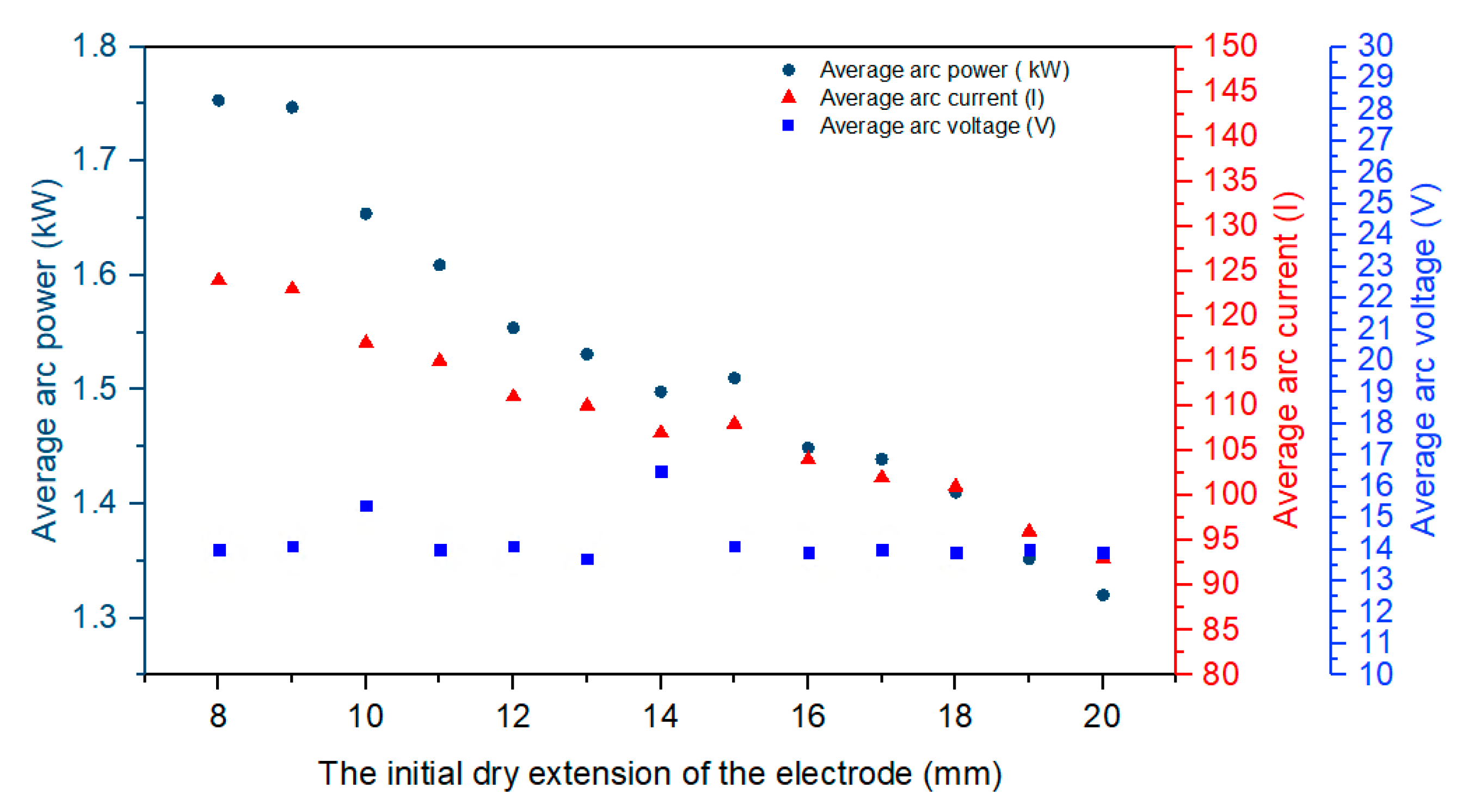
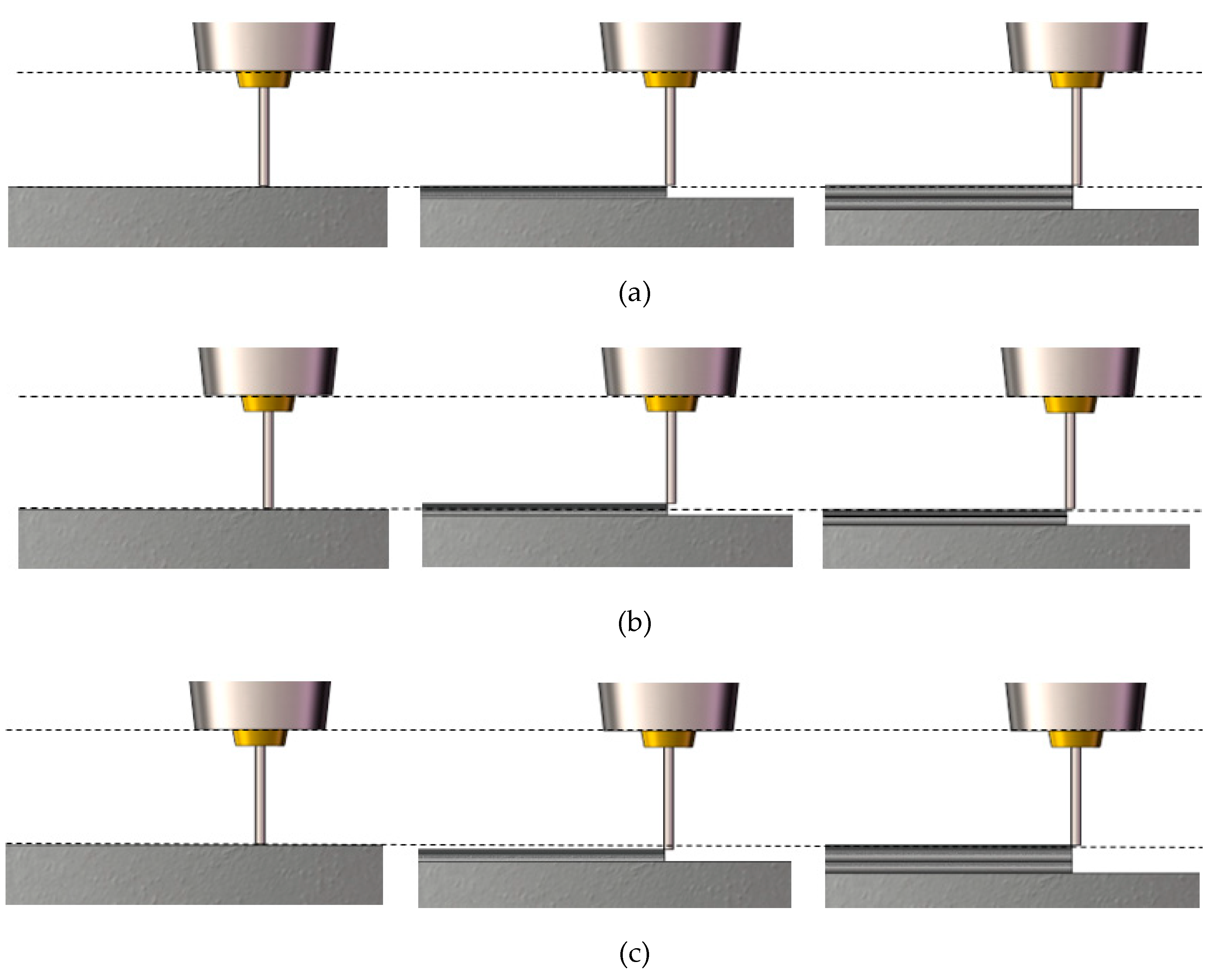
During the GMAW process, the changes in the distance between the torch and the top surface of the part cause the dry extensions of the electrode to vary; furthermore, this situation leads to an increase or decrease in the heat input into the molten pool. Therefore, the dry extension of the electrode is the key factor that influences the geometry of the welding bead, especially the layer height; it has a compensating effect that makes the actual layer height close to the predefined value, so the deposited layer height can maintain a stable state.

Author Contributions

H.S. developed the idea for the study. R.D. performed the research, analyzed data and wrote the manuscript. B.L., S.T. and S.L. discussed the results and revised the manuscript. All authors have read and agree to the published version of the manuscript.

Funding

This research was funded by the National Nature Science Foundation of China (No. 51975518), the Science Fund for Creative Research Groups of the National Natural Science Foundation of China (No. 51821093), the Key Research and Development Plan of Zhejiang Province (No. 2018C01073), the Ningbo Science and Technology Plan Project (No. 2019B10072), and the Fundamental Research Funds for the Central Universities (No. 2019QNA4004).

Conflicts of Interest

The authors declare no conflict of interest. The funders had no role in the design of the study; in the collection, analyses, or interpretation of data; in the writing of the manuscript; or in the decision to publish the results.

References

  1. Liu, B.; Shen, H.; Deng, R.; Li, S.; Tang, S.; Fu, J.; Wang, Y. Research on a planning method for switching moments in hybrid manufacturing processes. J. Manuf. Process. 2020, 56, 786–795. [Google Scholar] [CrossRef]
  2. Mughal, M.P.; Fawad, H.; Mufti, R.A. Three-Dimensional Finite-Element Modelling of Deformation in Weld-Based Rapid Prototyping. Proc. Inst. Mech. Eng. Part C J. Mech. Eng. Sci. 2006, 220, 875–885. [Google Scholar] [CrossRef]
  3. Xiong, J.; Zhang, G. Adaptive control of deposited height in GMAW-based layer additive manufacturing. J. Mater. Process. Technol. 2014, 214, 962–968. [Google Scholar] [CrossRef]
  4. Xiong, X.; Zhang, H.; Wang, G. Metal direct prototyping by using hybrid plasma deposition and milling. J. Mater. Process. Technol. 2009, 209, 124–130. [Google Scholar] [CrossRef]
  5. Xiong, J.; Zhang, G.; Hu, J.; Wu, L. Bead geometry prediction for robotic GMAW-based rapid manufacturing through a neural network and a second-order regression analysis. J. Intell. Manuf. 2012, 25, 157–163. [Google Scholar] [CrossRef]
  6. Panchagnula, J.S.; Simhambhatla, S. Manufacture of complex thin-walled metallic objects using weld-deposition based additive manufacturing. Robot. Comput. Manuf. 2018, 49, 194–203. [Google Scholar] [CrossRef]
  7. Panchagnula, J.S.; Simhambhatla, S. Feature based Weld-Deposition for Additive Manufacturing of Complex Shapes. J. Inst. Eng. (India) Ser. C 2018, 99, 285–292. [Google Scholar] [CrossRef]
  8. Zhou, X.; Zhang, H.; Wang, G.; Bai, X. Three-dimensional numerical simulation of arc and metal transport in arc welding based additive manufacturing. Int. J. Heat Mass Transf. 2016, 103, 521–537. [Google Scholar] [CrossRef]
  9. Ogino, Y.; Asai, S.; Hiřata, Y. Numerical simulation of WAAM process by a GMAW weld pool model. Weld. World 2018, 62, 393–401. [Google Scholar] [CrossRef]
  10. Himmel, B.; Rumschöttel, D.; Volk, W. Thermal process simulation of droplet based metal printing with aluminium. Prod. Eng. Res. Devel. 2018, 12, 457–464. [Google Scholar] [CrossRef]
  11. Cho, M.H.; Lim, Y.C.; Farson, D.F. Simulation of weld pool dynamics in the stationary pulsed gas metal arc welding process and final weld shape. Weld. J.-N. 2006, 85, 271s–283s. [Google Scholar]
  12. Cho, M.H.; Farson, D.F. Understanding Bead Hump Formation in Gas Metal Arc Welding Using a Numerical Simulation. Met. Mater. Trans. A 2007, 38, 305–319. [Google Scholar] [CrossRef]
  13. Wang, Y.; Tsai, H. Impingement of filler droplets and weld pool dynamics during gas metal arc welding process. Int. J. Heat Mass Transf. 2001, 44, 2067–2080. [Google Scholar] [CrossRef]
  14. Wu, N.; Hua, X.; Ye, D.; Li, F. Understanding of humping formation and suppression mechanisms using the numerical simulation. Int. J. Heat Mass Transf. 2017, 104, 634–643. [Google Scholar] [CrossRef] [Green Version]
  15. Zhao, H.; Zhang, G.; Yin, Z.; Wu, L. A 3D dynamic analysis of thermal behavior during single-pass multi-layer weld-based rapid prototyping. J. Mater. Process. Technol. 2011, 211, 488–495. [Google Scholar] [CrossRef]
  16. Bai, X.; Colegrove, P.A.; Ding, J.; Zhou, X.; Diao, C.; Bridgeman, P.; Hönnige, J.R.; Zhang, H.; Williams, S. Numerical analysis of heat transfer and fluid flow in multilayer deposition of PAW-based wire and arc additive manufacturing. Int. J. Heat Mass Transf. 2018, 124, 504–516. [Google Scholar] [CrossRef]
Figure 1. Schematic of the GMAW-based additive manufacturing system.
Applsci 10 04322 g001
Figure 2. The relationship between the total height and the predefined layer height (PLH).
Applsci 10 04322 g002
Figure 3. The geometry of the welding beads with different values of the initial dry extension of the electrode (IDEE): (a) IDEE = 12 mm and (b) IDEE = 20 mm.
Applsci 10 04322 g003
Figure 4. The relationship of the initial dry extension of the electrode and the average arc parameters, including the average arc power, average arc current, and average arc voltage.
Applsci 10 04322 g004
Figure 5. The relationship between the initial dry extension of the electrode and the shape of the bead.
Applsci 10 04322 g005
Figure 6. The thin walls for different values of the predefined layer height (PLH): (a) PLH = 0.8 mm; (b) PLH = 0.9 mm; (c) PLH = 1.0 mm; (d) PLH = 1.1 mm; and (e) PLH = 1.2 mm.
Applsci 10 04322 g006
Figure 7. The relationship of the ideal predefined layer height with the welding speed and wire feed speed.
Applsci 10 04322 g007
Figure 8. The geometry model of the computational domain.
Applsci 10 04322 g008
Figure 9. The simulation results for the 8 mm initial dry extension of electrode: (a) the side view; (b) the sectional view.
Applsci 10 04322 g009aApplsci 10 04322 g009b
Figure 10. The simulation results for the 12 mm initial dry extension of electrode: (a) the side view; (b) the sectional view.
Applsci 10 04322 g010
Figure 11. The simulation results for the 20 mm initial dry extension of electrode: (a) the side view; (b) the sectional view.
Applsci 10 04322 g011
Figure 12. The change of the temperature at the center of the molten pool under the arc with different values for the initial dry extension of the electrode.
Applsci 10 04322 g012
Figure 13. The states of the wire and molten pool with different heights of the substrate: (a) the substrate is in a higher position; (b) the substrate is in a lower position.
Applsci 10 04322 g013
Figure 14. A thin wall with a predefined layer height that is larger than the ideal value.
Applsci 10 04322 g014
Figure 15. The changes in the dry extension of the electrode during multilayer manufacturing: (a) the layer height is equal to the predefined value; (b) the layer height is more than the predefined value; and (c) the layer height is less than the predefined value.
Applsci 10 04322 g015
Figure 16. The manufactured models with the predefined layer height set to 0.85 mm, and other manufacturing parameters match this value: (a) a cylindrical model; (b) a hexagonal prism model; (c) a columnar model of heterosexual cross section.
Applsci 10 04322 g016
Table 1. Width and height of the welding bead with different PLH.
PLH (mm)SMD (mm)Total Height (mm)Deviation (mm)Width (mm)
0.8080.0082.58−2.586.14
0.8181.0083.48−2.486.00
0.8282.0084.12−2.126.08
0.8383.0084.26−1.265.70
0.8484.0084.34−0.345.86
0.8585.0084.880.125.78
0.8686.0085.520.485.86
0.8787.0086.260.745.98
0.8888.0086.501.505.88
0.8989.0087.781.225.76
0.9090.0087.882.125.78
0.9191.0088.502.505.64
0.9292.0088.803.205.54
0.9393.0089.463.545.84
0.9494.0089.924.085.48
0.9595.0090.664.345.54
0.9696.0091.744.264.95
1.00100.0095.284.724.92
1.05105.0098.666.344.90
1.10110.00102.207.804.72
1.15115.00104.6810.324.40
1.20120.00108.0411.964.06
Table 2. Thermophysical material properties of ER304 steel used in simulation.
NomenclatureValue
Density8.02 g/cm3
Viscosity0.008 g/cm/s
Thermal conductivity1.48 × 106 erg/cm/s/K
Specific heat4.8 × 106 erg/g/K
Latent heat of fusion2.61 × 109 erg/g
Liquidus temperature1727.15 K
Solidus temperature1633.15 K
Emissivity0.5
Surface tension coefficient1200 g/s2
Environment temperature300 K
Table 3. Simulation parameters.
SymbolNomenclatureSymbolNomenclature
V Velocity vector σ P Gaussian pressure distribution parameter
RSORMass source term γ Surface tension
ρ Zone density at current cell γ 0 The surface tension of pure metal at the melting point
ρ 0 Density of materialAThe negative of surface tension gradient for pure metal
P h Hydrodynamic pressure η Arc efficiency
μ Kinematic viscosityU, IWelding voltage and current
fAcceleration due to body force σ a Gaussian heat distribution parameter
KDrag coefficient J r , J z Radial and axial current density
hInternal energy per unit mass B θ Self-induced magnetic field
κThermal conductivity h c Heat transfer coefficient
RISOREnergy source term σ Boltzmann constant
TTemperatureu, v, wThe velocity in x y z direction
TWHeat structure surface temperature n Normal to the free surface
AWHeat structure surface area v n Normal velocity vector
Ts, TlSolidus and liquidus temperature P a r c Arc pressure
T0Environment temperature R 1 , R 2 Principal radius of surface curvature
FVolume fraction of fluidCs, ClSpecific heat of the solid and liquid phases
ρ s , ρ l Solid and liquid density

