Abstract
Modulation bandwidth enhancement of directly modulated semiconductor lasers (DMLs) has attracted broad interest to accommodate the tremendously growing demand for network traffic. In this paper, a monolithically integrated mutually coupled (IMC) laser for the O-band is demonstrated both numerically and experimentally. The direct modulation bandwidth was enhanced utilizing a photon–photon resonance (PPR) effect based on the mutual injection-locking technique. The IMC laser consisted of two distributed feedback (DFB) laser sections with a semiconductor optical amplifier (SOA) section in between. The relationship between the PPR frequency and SOA length was analyzed numerically to achieve a flat modulation response by optimizing the SOA length. Then, an enhanced 3-dB bandwidth of 38.7 GHz was realized experimentally, a nearly threefold enhancement over the modulation bandwidth of a solitary DFB laser at the same bias. Moreover, clear open eyes up to 40 Gb/s transmission over a 25-km single-mode fiber were achieved. Although the dynamic extinction ratio of the eye diagram was 1.1 dB, it can be further improved by increasing the mutual injection locking range of the IMC laser.
1. Introduction
Recently, data traffic has been growing rapidly due to the increasing demand for high-definition video streaming, cloud computing, and a massive internet-of-things. Consequently, explosive bandwidth growth is expected in data centers and front haul deployments for fifth-generation wireless systems. To meet this need, high-speed optical transmitters that support data rates of 50, 100, and even 400 Gb/s are in great demand [1]. Compared with external modulators, the directly modulated semiconductor laser (DML) is an attractive candidate due to its compact size, cost-effectiveness, and high energy efficiency. To support the rapid increase of transmission rates over single lambda [2], further improving the modulation bandwidth of the DML is the primary challenge.
One approach to achieving this is to increase the carrier-photon resonance (CPR) frequency by increasing the differential gain through optimizing multiple quantum well (MQW) structures, reducing the photon lifetime via shortening the cavity length [3,4,5,6] or reducing parasitic parameters [7]. Another approach entails utilizing the photon–photon resonance (PPR) effect based on optical feedback [8,9,10] or optical injection-locking techniques [11,12,13]. The PPR effect is contributed by the cavity mode close to the main mode, with a suitable side-mode suppression ratio (SMSR), wherein a modulation sideband is resonantly enhanced by the cavity mode [10]. Consequently, a PPR peak that exceeds the usual CPR frequency is formed on the frequency response, which could contribute to further extending the modulation bandwidth. Utilizing optical feedback, several high-performance laser structures have been proposed, such as the passive feedback laser [9] and distributed reflector laser [10]. However, both are fabricated utilizing active–passive integration techniques and buried heterostructures, which increases their manufacturing costs and complications.
For optical injection technology, one scheme involves employing a unidirectional optical injection-locking (OIL) system [13]. Several systematic studies on the injection-locking behaviors and modulation characteristics of OIL systems have been conducted [11,12,13,14,15,16,17], and an enhanced modulation bandwidth of 44 GHz has been achieved [18]. However, OIL systems are bulky and complex owing to their use of discrete optical components, especially when the isolator causes difficulty in implementing monolithic integration.
A more practical OIL technology scheme has been proposed based on the optical mutual injection-locking (MIL) technique, which facilitates the implementation of monolithic integration by removing the optical isolator. Several integrated mutually coupled (IMC) lasers are employed to achieve MIL [19,20,21,22,23,24,25,26]. The PPR effect on the IMC lasers is attributed to the red-shift cavity mode due to optical injection from one of the laser sections [27]. The research’s detailed enhanced modulation performances are listed in Table 1, where fR is the resonance frequency and f3dB is the 3-dB modulation bandwidth of the lasers. The enhancement of resonance frequency has also been reported with simultaneous improvements of other laser characteristics, including nonlinear distortion suppression [19], relative intensity noise reduction [23], chirp reduction [24], and linewidth narrowing [27]. Moreover, a modulation bandwidth enhancement of 37 GHz and an open eye of 36 Gb/s have been reported in mutually coupled vertical-cavity surface-emitting laser (VCSEL) arrays [25]. However, for edge-emitting lasers, most IMC lasers only achieve an increase of the resonance (or PPR) frequency without an enhanced modulation bandwidth, which is induced by the low-frequency roll-off effect and the deep gap between the CPR and PPR frequencies. This was caused by a long cavity length of directly modulated laser section [24], RC bandwidth roll-off effect in-package [28], and intrinsic bandwidth limitation induced by the first-order pole frequency [11]. Although an enhanced modulation bandwidth of 18.7 GHz has been demonstrated in our previous work [29], the tuning range of the laser section for the mutually injection-locked state was only 4 mA due to poor single-mode stability resulting from the uniform grating and laser facets without AR coatings. As such, further enhancement of the modulation bandwidth is limited, and the practical performance of IMC lasers under large-signal modulation has not been reported. Therefore, it is important to ensure that IMC lasers work under a stable MIL state, as this enables the modulated laser section to work at a higher bias and helps increase the CPR frequency and mitigate its roll-off effect. Moreover, the cavity parameters of IMC lasers need to be well-designed to achieve an appropriate PPR frequency for modulation response enhancement [27]. Additionally, the PPR peak should not be too far from the CPR peak, or there will be a significant gap between the two resonance peaks, which is detrimental to broadband communication [8].

Table 1.
Representative modulation performances of different integrated mutually coupled (IMC) lasers.
In this paper, we demonstrate modulation bandwidth enhancement and large-signal modulation performance of IMC lasers for the O-band with identical MQW layers under MIL. The IMC laser is composed of two DFB laser sections with an SOA section in between. Phase-shifted grating and an antireflection (AR) coating are adopted in the IMC laser to achieve stable single-mode operation and increase the locking range. Furthermore, the PPR frequency’s dependence on the SOA length has been investigated by numerical simulation, and it is observed that the IMC laser can effectively take advantage of the PPR effect by optimizing the SOA length. In addition, by adjusting the currents of three sections, flat small-signal response with a 3-dB bandwidth of 38.7 GHz was realized in our device with an optimum SOA length. Moreover, at a modulation rate of 40 Gb/s, clearly opened eyes for the case of the back-to-back (BTB) and 25-km single-mode fiber (SMF) transmissions were realized.
2. Numerical Simulation and Device Design
2.1. Numerical Simulation
Several simulation studies on IMC lasers have been conducted based on the modified rate equations model [20,22,24], which provides a physical intuition of the dynamics of IMC lasers with the coupling strength and detuning frequency. However, this is less practical for integrated device designs, considering the complicated interactions of each section and difficulty extracting the coupling parameters under different bias conditions. Thus, a method based on the traveling-wave (TW) model is preferable for analyzing the static and dynamic performances in a multi-section laser, which comprises the spatial-temporal effects along the cavity [30,31]. The slowly varying envelopes of the propagating electric field obey the following equations:
where Ef and Eb are the complex-valued envelopes of the forward and backward traveling optical fields, respectively, vg is the group velocity of the optical mode, κ±l is the coupling coefficient in the DFB section, δ is the deviation of the propagation constants, Γ is the confinement factor, g is the gain coefficient, α is the internal loss, and Ff,b is the stochastic noise donated by the spontaneous emission. Here, to simulate the IMC laser, we used a commercial simulation package, VPItransmissionMakerTM (VPI), with a transmission line model based on the TW model.
Figure 1 shows the structure of the IMC laser in our simulation, which is composed of two DFB sections on both sides and an SOA section in the middle that serves as a tuning section to adjust the coupling strength and coupling phase. The IMC laser works under the MIL state by adjusting the current of three sections, which leads to an appropriate detuning frequency, coupling strength, and coupling phase. The DFB section under modulation was named DFB1, while the DFB section under only DC bias was named DFB2. The length of both DFB sections was fixed at 220 μm to ensure an adequate output power and CPR frequency. The grating phase shift and reflectivity of the facets were based on the device’s manufacturing structure. The other parameters used in the simulation were chosen after referring to [24,31,32] and are listed in Table 2. In both the simulation and experiments, the laser output was coupled from the facet of DFB1.
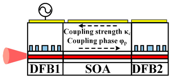
Figure 1.
Conceptual diagram of the integrated mutually coupled (IMC) laser in the simulation.
Table 2.
Parameters used in the simulation.
Initially, the small-signal modulation response of the IMC laser under various DC biasing was investigated via simulation. As shown in Figure 2a, when ISOA and IDFB2 were fixed at 2 and 55 mA, respectively, the magnitude of the PPR peak was raised from −2.4 to 5 dB, with IDFB1 varying from 85 to 95 mA. This was attributed to the enhancement of the first-order pole frequency due to the increase of the photon number in the DFB1 cavity [11]. Then, IDFB2 varied from 55 to 75 mA (Figure 2b), while IDFB1 and ISOA were fixed at 95 and 2 mA, respectively. Since VPI does not consider the heating effect, the lasing wavelength of the solitary DFB2 was blue-shifted with an increased IDFB2. Consequently, the detuning frequency Δf = f1−f2 decreased monotonically from positive to negative, as shown in the schematic inset of Figure 2b, wherein f1 and f2 are the lasing frequency of DFB1 and DFB2, respectively. This led to increased damping of the PPR peak and a decreased PPR frequency (Figure 2b), which coincided with a previous report’s results [24]. When the currents of DFB1 and DFB2 were fixed at 95 and 55 mA, respectively, the SOA current varied from 1 to 5 mA. The change of coupling phase and change of gain in the SOA were estimated at about 0.51 π and 0.55 dB, respectively, as ISOA increased from 1 to 5 mA. As shown in Figure 2c, the magnitude of the PPR peak decreased primarily due to the coupling phase changes. However, the PPR frequency hardly changed, which may be because of the relatively small change in the coupling strength due to the small varying range of the SOA current. When the SOA section was biased above 5 mA, the IMC laser entered the unlocked state due to the phase condition change [33]. A maximal modulation bandwidth of approximately 40 GHz was obtained by adjusting the currents of the three sections.
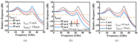
Figure 2.
Simulated small-signal modulation response of the IMC laser with different (a) IDFB1, (b) IDFB2, and (c) ISOA values. Inset: schematic diagram of the variation of the detuning frequency as IDFB2 varied.
The cavity length is also a vital parameter in IMC lasers [24], but the relationship between the PPR frequency and cavity length has rarely been studied. To investigate its impact, we calculated the normalized small-signal response with different SOA lengths when the DFB sections were fixed at 220 μm. The DFB1 current was fixed at 100 mA, while the DFB2 current was scanned to push the IMC laser into the MIL state. Meanwhile, the SOA current was adjusted to make the SMSR of lasing mode as similar as possible in IMC lasers with different SOA lengths. The modulation responses are depicted in Figure 3a. The PPR frequency increased as the SOA length decreased, and the dip deepened between the CPR and PPR frequencies. A maximum PPR frequency of 46.5 GHz was obtained when the SOA length was 220 μm. Although shorter SOA lengths caused a higher PPR frequency (Figure 3b), the frequency response between the CPR and PPR peaks was lower than −3 dB when the SOA length was shorter than 280 μm. Hence, the SOA length should be carefully designed to modify frequency spacing between CPR and PPR peak for achieving a flat small-signal modulated response, as mentioned above. To balance the flat response and maximum bandwidth, the length of 360 μm was chosen to fabricate our device.
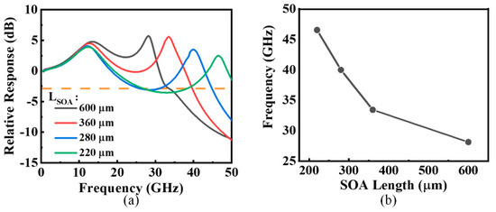
Figure 3.
(a) Simulated small-signal modulated response of the IMC laser with different semiconductor optical amplifier (SOA) lengths. (b) The dependence of the photon–photon resonance (PPR) frequency on the SOA length. The SOA length was varied from 220 to 600 μm, and the distributed feedback (DFB) length was fixed at 220 μm. IDFB1 was fixed at 100 mA, while ISOA and IDFB2 were adjusted to ensure that the device would work under the mutual injection-locking (MIL) state with a similar suitable side-mode suppression ratio (SMSR).
2.2. Device Structure and Fabrication
According to the simulation results above, we designed and fabricated the IMC laser via the identical active layer approach with a simple and cost-effective conventional laser manufacturing process [34] (Figure 4a,b). The device structure was grown on an n-type InP substrate via metalorganic chemical vapor deposition (MOCVD). The MQWs were sandwiched between 50-nm-thick graded-index separate-confinement heterojunction (GRIN-SCH) InGaAlAs layers, which consisted of six InGaAlAs wells with 1.2% compressive strain (λPL = 1.28 μm, PL is photoluminescence). Figure 4c shows the λ/4 shifted grating in both DFB sections with the same grating pitch, as defined by e-beam lithography on a 35-nm-thick grating layer upon GRIN-SCH. In the final MOCVD growth step, a p-InP cladding layer and InGaAs contact layer were grown on the whole wafer. A double-trench inverted-trapezoidal-shaped ridge of 3.5-μm width was formed by wet etching (Figure 4d). Additionally, the 20-μm gap between each adjacent section was formed by etching the InGaAs contact layer to provide electrical isolation. To reduce the parasitic capacitance, polyimide material was spun to fill the trenches for planarization. After the sample chip was cleaved, both facets were deposited with AR dielectric coatings. The optical feedback from each facet’s reflection was significantly reduced by the AR coatings, which helped alleviate the influence of optical feedback on the working condition of the IMC laser to ensure the single-mode stability of the DFB sections.
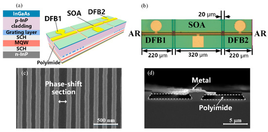
Figure 4.
(a) Schematic and (b) optical photograph of the IMC laser. SEM of (c) the top view of the grating and (d) cross-section of the mesa.
3. Experimental Results and Discussion
3.1. Small-Signal Modulation Response
The fabricated IMC laser chip was mounted onto an AlN submount upon a Cu heat sink, enabling the microwave signal to feed into DFB1 through a ground–signal–ground (GSG) probe. The stage temperature was stabilized at 20 °C by a thermoelectric cooler for detailed device characterization, and each section was driven by a precise current source. The laser from the DFB1 section’s facet was coupled into a lensed SMF and tested by an optical spectrum analyzer (Advantest Q8384) with 0.01-nm resolution. Meanwhile, the small-signal modulation responses were measured with a vector network analyzer (VNA, HP 8510C).
The working condition of the IMC laser with varying IDFB1 values was investigated, while IDFB2 and ISOA were fixed at 40 and 5 mA, respectively. Figure 5 shows the optical spectra of the IMC laser in the unlocked and MIL states, respectively. As shown in the red curve in the figure, the lasing mode of the IMC laser with IDFB1 = 131 mA was locked in single-mode and entered the MIL state. Additionally, a small sidelobe appeared (Figure 5) due to the red-shifted cavity mode caused by the interaction between the two lasers under the MIL state [24]. Upon increasing IDFB1, the IMC laser went through a series of nonlinear dynamic states [33]. When the DFB1 section was biased at 142 mA, the IMC laser operated under the unlocked state with an SMSR below 10 dB, as shown by the dark curve in Figure 5.
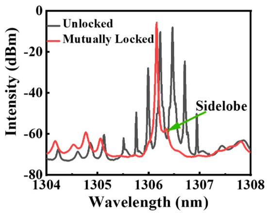
Figure 5.
The optical spectra of the IMC laser with IDFB1 = 131 mA (red) under the MIL state and IDFB1 = 142 mA (dark) under the unlocked state. Here, IDFB2 and ISOA were fixed at 40 mA and 5 mA, respectively.
For comparison, the solitary DFB laser was cleaved from the same wafer as the IMC laser and had the same structure as the DFB1 section of the IMC laser. The lasing spectra of the solitary DFB (brown line) and the IMC laser (red line), biased at the same current of 130 mA, are shown in Figure 6a. Both devices can lase in single mode with an SMSR over 47 dB. The detailed lasing spectrum under the MIL range is displayed in Figure 6a, which exhibits a stable single-mode with an SMSR over 32 dB in the whole range from 125 to 139 mA. This indicates that the tuning range was nearly four times larger than in our previous work [29]. The small-signal response of the solitary DFB laser (brown line) was measured, as depicted in Figure 6b. The modulation bandwidth was only 13.1 GHz when the laser was biased at 130 mA. Compared with the response of the solitary DFB laser, it can be seen that the CPR peak of the IMC laser was slightly suppressed and that the modulation bandwidth was extended by the PPR peak due to MIL (Figure 6b) [15]. More importantly, a PPR peak at a higher frequency corresponding to the mode spacing between the main mode and sidelobe was formed to further enhance the modulation bandwidth of the IMC laser, which was caused by MIL. For IDFB1 = 139 mA, the mode spacing was about 0.17 nm (Figure 6a), corresponding to the PPR frequency of around 29.2 GHz. As IDFB1 increased, the sidelobe’s intensity increased, resulting in higher overshooting of the PPR peak in the frequency response (Figure 6b). This increase of IDFB1 led to the increase of the photon number in the whole cavity, resulting in the enhancement of the first-order pole frequency [11], thus confirming the numerical simulation results above. Moreover, an enhanced 3-dB bandwidth of 34 GHz was obtained when IDFB1 ranged from 134 to 139 mA.
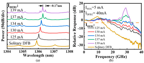
Figure 6.
(a) Lasing spectra and (b) corresponding small-signal modulation response of the solitary laser (brown line) and the IMC laser with different IDFB1 values. Here, IDFB2 and ISOA of the IMC laser were fixed at 40 and 5 mA, respectively.
Then, the influence of IDFB2 on the modulation response of the IMC laser was investigated, wherein the IDFB1 and ISOA were fixed at 136 and 5 mA, respectively. As shown in Figure 7a, the optical spectrum indicated that the sidelobe was gradually moving farther from the main mode and that the intensity increased as IDFB2 increased. As a result, the magnitude and frequency of the corresponding PPR peak increased (Figure 7b). The trend seemed to be opposite that of the simulation results. In the experiment, the lasing wavelength of DFB1 biased at a higher current was on the long-wavelength side of the lasing mode of DFB2 due to the heating effect. As IDFB2 increased, the wavelength of DFB2 moved toward a longer wavelength; hence, the detuning frequency increased from negative to positive, as depicted in the inset of Figure 7b. Therefore, the SMSR of the lasing mode decreased, resulting in reducing the damping of the PPR peak [13,24]. When IDFB2 was above 50 mA, the IMC laser was closer to the locking range boundary, causing a narrow and sharp PPR peak. The optical spectrum is like the black line in Figure 5, which indicates that the IMC laser has entered an unlocking state [33]. It is also called high-frequency pulsations [26] or a mode beating state [31]. Although the modulation response between the CPR and PPR peaks dropped below −3 dB, it could still serve well for narrow-band applications [20] or optoelectronic oscillators [35]. Though the simulation results tuning IDFB2 appeared to differ from the experiment, the frequency response’s dependence on the detuning frequency was consistent. Moreover, the detuning frequency’s change with varying currents could be practical for adjusting the working condition of the IMC laser. Additionally, the simulation could be modified by calibrating the VPI model in an upgraded version of VPI, considering the heating effect.
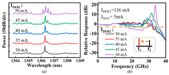
Figure 7.
(a) Lasing spectra and (b) corresponding small-signal modulation response of the IMC laser with different IDFB2 values. Here, IDFB1 and ISOA were fixed at 136 and 5 mA, respectively. Inset: schematic diagram of the detuning frequency’s variation as IDFB2 varied.
As shown in Figure 8, the IMC laser’s modulation response was extremely sensitive to the SOA’s injection current. When ISOA increased, the coupling strength between DFB1 and DFB2 increased. Moreover, the PPR frequency could be increased by increasing the coupling strength in the MIL scheme [24]. Consequently, the mode separation between the main mode and sidelobe increased from 0.135 to 0.22 nm by increasing the SOA current, which corresponded to the PPR frequency increase from 23.4 to 38.4 GHz (Figure 8b). When ISOA varied to 7 mA, the PPR peak was slightly damped, primarily due to the higher coupling strength [15,24]. Then, when ISOA was over 7 mA, the IMC laser worked close to the locking range boundary routing to the unlocked state. This was dominated by the change of the coupling phase because the working condition was more sensitive to it, as mentioned previously. As a result, the SMSR of the IMC laser degraded, and the PPR peak became higher and sharper again, inducing an unfilled gap between the CPR and PPR peaks. Thus, there is a trade-off between a higher PPR frequency and flat modulation response. For broadband communication, a flat modulation response curve could be obtained by adjusting the bias current. Here, a maximum flat modulation bandwidth of 38.7 GHz was obtained as ISOA = 7 mA.
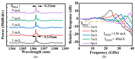
Figure 8.
(a) Lasing spectra and (b) corresponding small-signal modulation response of the IMC laser with different ISOA values. Here, IDFB1 and IDFB2 were fixed at 136 and 40 mA, respectively.
3.2. Large-Signal Modulation Performance
The large-signal modulation performance of the IMC laser was investigated via a data transmission experiment. As shown in Figure 9, non-return-to-zero (NRZ) signals with a 231−1 pseudorandom binary sequence were generated from a pulse pattern generator (SHF-12125B). Then, the electrical NRZ signals were amplified to approximately 1.2 V peak-to-peak by a broadband electrical amplifier. The data signals were combined with a DC injection current through a broadband bias tee and applied to the DFB1 section using a GSG probe. The IMC laser was under MIL with DFB1 biased at 136 mA, while ISOA and IDFB2 were adjusted to obtain a flat frequency response. The eye diagram was observed by a sampling oscilloscope (Keysight 86100D) using an optical module (Keysight 86116C) as a photodetector. As shown in Figure 10, the BTB eye diagram of the solitary DFB laser was very poor at 25 Gb/s and even closed at 40 Gb/s due to the small modulation bandwidth of 13.1 GHz. However, the eye diagram’s quality was significantly improved when the IMC laser was biased into the MIL state, in which clear open eyes could be observed at both 25 and 40 Gb/s. The dispersion of the 25-km SMF was about −15 ps/nm at an emission wavelength of 1306 nm. The eye diagrams maintained their shape after the 25-km transmission, which partially benefited from the SMF dispersion. In comparison with the quality of the electrical signal, the measurement was primarily limited by the test system.
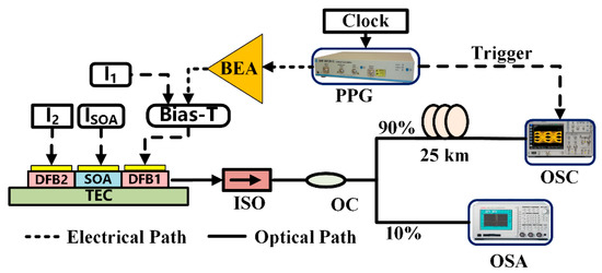
Figure 9.
Experimental setup for the eye diagram. PPG: pulse pattern generator; BEA: broadband electrical amplifier; ISO: isolator; OC: optical coupler; OSA: optical spectrum analyzer; OSC: oscilloscope; TEC: thermoelectric cooler.
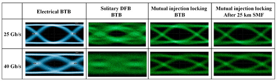
Figure 10.
The 25 and 40 Gb/s non-return-to-zero eye diagrams of the solitary DFB and IMC lasers under the MIL state for back-to-back (BTB) configuration and eye diagrams of the IMC laser under the MIL state for 25-km SMF transmission.
However, in Figure 10, the dynamic extinction ratio (ER) of the eye diagram was 1.1 dB due to the limitation of the MIL range with the change of DFB1′s current, which influenced the working condition of the IMC laser (Figure 6). The IMC laser could maintain the MIL state when the IDFB1 was within the limited range. When the DFB1 section was applied to a higher modulation voltage, the IMC laser may have left the MIL state, inducing the degradation of the modulation response, or entered a nonlinear dynamic state. This resulted in a non-flat frequency response with a significant gap, causing the deterioration of the eye diagram. To further improve the large-signal modulation performance, it is desirable to adopt complex-coupled gratings [36], more reliable electrical isolation, and detuned gratings [26]. The single-mode stability of the DFB section could be improved by adopting the complex-coupled gratings [36], which are helpful to ensure the IMC laser is working in a more stable locking state with a large tuning range of IDFB1. In addition, the electrical crosstalk from each adjacent section can be reduced by a more reliable electrical isolation, which allows each section to work more independently and prevents changing the current of the SOA section when DFB1 is under modulation. This allows a more stable injection locking state for the IMC laser. Moreover, the detuned gratings of the IMC lasers can be used to optimize the PPR frequency and working conditions [26], which may facilitate better bias condition of each section to allow a larger locking range of the IMC laser as DFB1 is modulated.
Moreover, the chirp performance of the IMC laser was investigated by measuring the optical spectra under large signal modulation. For comparison, we tested the optical spectra with a 1.5 nm span under 10 Gb/s modulation for a dynamic ER of 3.2 dB. The modulation rate was selected according to the limited modulation bandwidth of the solitary DFB laser. As shown in Figure 11a,b, the adiabatic chirp of solitary laser is about 9.3 GHz. However, it is hard to estimate the adiabatic chirp of the IMC laser due to the limited resolution of the equipment. This indicates that the adiabatic chirp of the DFB laser is reduced by a mutual injection lock. Then, we decreased the IDFB1 to make the IMC laser work under a more stable locking state to achieve higher ER for 25 Gb/s, while the small-signal modulation response was relatively small, as shown in Figure 6. The optical spectra of the IMC laser under the mutually injection-locked state at 25 Gb/s for a dynamic ER of 3.1 dB is shown in Figure 11c. It can be seen that the adiabatic-chirp cannot be recognized in the spectra, which indicates the transient-chirp is dominated.
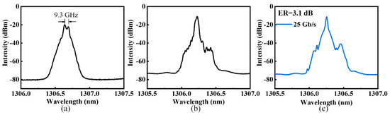
Figure 11.
The adiabatic chirp of (a) the solitary laser and (b) the IMC laser under the MIL state with the same bias condition and dynamic ER. (c) The optical spectra of the IMC laser under the MIL state at 25 Gb/s for a dynamic ER of 3.1 dB.
4. Conclusions
In summary, the modulation bandwidth of the IMC laser for the O-band was enhanced to 38.7 GHz by exploiting the PPR effect under MIL and mitigating the roll-off effect in the CPR frequency. The MIL behavior and modulation response of the IMC laser were analyzed both numerically and experimentally. The characteristics of the modulation response with the tuning current of each section and the dependence of the PPR frequency on the SOA length were investigated to optimize the IMC laser. By adopting phase-shifted grating and AR coatings, a relatively wide locking range was achieved. As a result, 40 Gb/s NRZ at 1306 nm for both BTB and 25-km SMF transmissions were demonstrated using the IMC laser. Enhanced bandwidth and large-signal modulation were achieved for the IMC laser, demonstrating that an effective combination of a proper PPR peak and higher CPR frequency further enhanced the modulation bandwidth beyond 40 GHz. Whereas the dynamic ER of the eye diagram was 1.1 dB, it can be further improved by modifying the bias condition of the DFB1 section, adopting complex-coupled gratings, more reliable electrical isolation, and detuned gratings. Thus, IMC lasers could play a promising role in high-speed applications in the future due to their simple conventional manufacturing process and highly improved modulation performance.
Author Contributions
Conceptualization, Q.K., Y.M., and W.Z.; methodology, Y.M. and W.Z.; formal analysis, W.Z.; investigation, W.Z.; writing—original draft preparation, W.Z.; writing—review and editing, Q.K. and Y.M.; visualization, W.Z.; supervision, Q.K., Y.H., D.L., L.Z., and W.W.; project administration, Q.K.; funding acquisition, Q.K. All authors have read and agreed to the published version of the manuscript.
Funding
This work was funded by the National Key R&D Program of China (Grant No. 2018YFA0209000) and the National Natural Science Foundation of China (NSFC) under Grant No. 61574137.
Conflicts of Interest
The authors declare no conflict of interest.
References
- IEEE Standard 802.3bs. Available online: https://standards.ieee.org/standard/802_3bs-2017.html (accessed on 10 October 2019).
- 100G Lambda MSA. Available online: http://100glambda.com/specifications (accessed on 10 October 2019).
- Matsui, Y.; Murai, H.; Arahira, S.; Kutsuzawa, S.; Ogawa, Y. 30-GHz bandwidth 1.55-μm strain-compensated InGaAlAs-InGaAsP MQW laser. IEEE Photon. Technol. Lett. 1997, 9, 25–27. [Google Scholar] [CrossRef]
- Kobayashi, W.; Ito, T.; Yamanaka, T.; Fujisawa, T.; Shibata, Y.; Kurosaki, T.; Kohtoku, M.; Tadokoro, T.; Sanjoh, H. 50-Gb/s Direct Modulation of a 1.3-μm InGaAlAs-Based DFB Laser With a Ridge Waveguide Structure. IEEE J. Sel. Top. Quantum Electron. 2013, 19, 1500908. [Google Scholar] [CrossRef]
- Sasada, N.; Nakajima, T.; Sekino, Y.; Nakanishi, A.; Mukaikubo, M.; Ebisu, M.; Mitaki, M.; Hayakawa, S.; Naoe, K. Wide-temperature-range (25°C to 80°C) 53-Gbaud PAM4 (106-Gb/s) Operation of 1.3-μm Directly Modulated DFB Lasers for 10-km Transmission. J. Lightwave Technol. 2019, 37, 1686–1689. [Google Scholar] [CrossRef]
- Selmic, S.R.; Tso-Min, C.; Jiehping, S.; Kirk, J.B.; Mantle, A.; Butler, J.K.; Bour, D.; Evans, G.A. Design and characterization of 1.3-μm AlGaInAs-InP multiple-quantum-well lasers. IEEE J. Sel. Top. Quantum Electron. 2001, 7, 340–349. [Google Scholar] [CrossRef]
- Chen, R.-Y.; Chen, Y.-J.; Chen, C.-L.; Wei, C.-C.; Lin, W.; Chiu, Y.-J. High-Power Long-Waveguide 1300-nm Directly Modulated DFB Laser for 45-Gb/s NRZ and 50-Gb/s PAM4. IEEE Photon. Technol. Lett. 2018, 30, 2091–2094. [Google Scholar] [CrossRef]
- Reithmaier, J.P.; Kaiser, W.; Bach, L.; Forchel, A.; Feies, V.; Gioannini, M.; Montrosset, I.; Berg, T.W.; Tromborg, B. Modulation speed enhancement by coupling to higher order resonances: A road towards 40 GHz bandwidth lasers on InP. In Proceedings of the International Conference on Indium Phosphide and Related Materials, Glasgow, Scotland, UK, 8–12 May 2005; pp. 118–123. [Google Scholar]
- Kreissl, J.; Vercesi, V.; Troppenz, U.; Gaertner, T.; Wenisch, W.; Schell, M. Up to 40-Gb/s directly modulated laser operating at low driving current: Buried-heterostructure passive feedback laser (BH-PFL). IEEE Photon. Technol. Lett. 2012, 24, 362–364. [Google Scholar] [CrossRef]
- Matsui, Y.; Schatz, R.; Pham, T.; Ling, W.A.; Carey, G.; Daghighian, H.M.; Adams, D.; Sudo, T.; Roxlo, C. 55 GHz Bandwidth Distributed Reflector Laser. J. Lightwave Technol. 2017, 35, 397–403. [Google Scholar] [CrossRef]
- Lau, E.K.; Zhao, X.; Sung, H.-K.; Parekh, D.; Chang-Hasnain, C.; Wu, M.C. Strong optical injection-locked semiconductor lasers demonstrating > 100-GHz resonance frequencies and 80-GHz intrinsic bandwidths. Opt. Express 2008, 16, 6609–6618. [Google Scholar] [CrossRef]
- Zhao, X.; Chang-Hasnain, C.J. A New Amplifier Model for Resonance Enhancement of Optically Injection-Locked Lasers. IEEE Photon. Technol. Lett. 2008, 20, 395–397. [Google Scholar] [CrossRef]
- Lau, E.K.; Liang, J.W.; Wu, M.C. Enhanced Modulation Characteristics of Optical Injection-Locked Lasers: A Tutorial. IEEE J. Sel. Top. Quantum Electron. 2009, 15, 618–633. [Google Scholar] [CrossRef]
- Lau, E.K.; Sung, H.-K.; Wu, M.C. Frequency Response Enhancement of Optical Injection-Locked Lasers. IEEE J. Quantum Electron. 2008, 44, 90–99. [Google Scholar] [CrossRef]
- Murakami, A.; Kawashima, K.; Atsuki, K. Cavity resonance shift and bandwidth enhancement in semiconductor lasers with strong light injection. IEEE J. Quantum Electron. 2003, 39, 1196–1204. [Google Scholar] [CrossRef]
- Wang, J.; Haldar, M.K.; Li, L.; Mendis, F.V.C. Enhancement of modulation bandwidth of laser diodes by injection locking. IEEE Photon. Technol. Lett. 1996, 8, 34–36. [Google Scholar] [CrossRef]
- Simpson, T.B.; Liu, J.M.; Gavrielides, A. Bandwidth enhancement and broadband noise reduction in injection-Locked semiconductor lasers. IEEE Photon. Technol. Lett. 1995, 7, 709–711. [Google Scholar] [CrossRef]
- Lau, E.K.; Hyuk-Kee, S.; Wu, M.C. Ultra-high, 72 GHz resonance frequency and 44 GHz bandwidth of injection-locked 1.55-um DFB lasers. In Proceedings of the Optical Fiber Communication Conference, Anaheim, CA, USA, 5–10 March 2006; p. OThG2. [Google Scholar]
- Sung, H.K.; Jung, T.; Ming, C.W.; Tishmin, D.; Tanbun-Ek, T.; Liou, K.Y.; Tsang, W.T. Modulation bandwidth enhancement and nonlinear distortion suppression in directly modulated monolithic injection-locked DFB lasers. In Proceedings of the MWP 2003 Proceedings. International Topical Meeting on Microwave Photonics, Budapest, Hungary, 10–12 September 2003; pp. 27–30. [Google Scholar]
- Chow, W.W.; Yang, Z.S.; Vawter, G.A.; Skogen, E.J. Modulation Response Improvement With Isolator-Free Injection-Locking. IEEE Photon. Technol. Lett. 2009, 21, 839–841. [Google Scholar] [CrossRef]
- Tauke-Pedretti, A.; Vawter, G.A.; Skogen, E.J.; Peake, G.; Overberg, M.; Alford, C.; Chow, W.W.; Yang, Z.S.; Torres, D.; Cajas, F. Mutual Injection Locking of Monolithically Integrated Coupled-Cavity DBR Lasers. IEEE Photon. Technol. Lett. 2011, 23, 908–910. [Google Scholar] [CrossRef]
- Yang, Z.; Tauke-Pedretti, A.; Vawter, G.A.; Chow, W.W. Mechanism for Modulation Response Improvement in Mutually Injection-Locked Semiconductor Lasers. IEEE J. Quantum Electron. 2011, 47, 300–305. [Google Scholar] [CrossRef]
- Anandarajah, P.M.; Latkowski, S.; Browning, C.; Zhou, R.; O’Carroll, J.; Phelan, R.; Kelly, B.; O’Gorman, J.; Barry, L.P. Integrated Two-Section Discrete Mode Laser. IEEE Photon. J. 2012, 4, 2085–2094. [Google Scholar] [CrossRef]
- Sun, C.; Liu, D.; Xiong, B.; Luo, Y.; Wang, J.; Hao, Z.; Han, Y.; Wang, L.; Li, H. Modulation Characteristics Enhancement of Monolithically Integrated Laser Diodes Under Mutual Injection Locking. IEEE J. Sel. Top. Quantum Electron. 2015, 21, 628–635. [Google Scholar] [CrossRef]
- Dave, H.; Liao, P.; Fryslie, S.T.M.; Gao, Z.; Thompson, B.J.; Willner, A.E.; Choquette, K.D. Digital Modulation of Coherently-Coupled 2×1 Vertical-Cavity Surface-Emitting Laser Arrays. IEEE Photon. Technol. Lett. 2019, 31, 173–176. [Google Scholar] [CrossRef]
- Mohrle, M.; Sartorius, B.; Bornholdt, C.; Bauer, S.; Brox, O.; Sigmund, A.; Steingruber, R.; Radziunas, H.; Wunsche, H.J. Detuned grating multisection-RW-DFB lasers for high-speed optical signal processing. IEEE J. Sel. Top. Quantum Electron. 2001, 7, 217–223. [Google Scholar] [CrossRef]
- Ma, W.; Xiong, B.; Sun, C.; Ke, X.; Wang, J.; Hao, Z.; Wang, L.; Han, Y.; Li, H.; Yu, J.; et al. Linewidth Narrowing of Mutually Injection Locked Semiconductor Lasers with Short and Long Delay. Appl. Sci. 2019, 9, 1436. [Google Scholar] [CrossRef]
- Zhang, Y.; Li, L.; Zhou, Y.; Zhao, G.; Shi, Y.; Zheng, J.; Zhang, Z.; Liu, Y.; Zou, L.; Zhou, Y.; et al. Modulation properties enhancement in a monolithic integrated two-section DFB laser utilizing side-mode injection locking method. Opt. Express 2017, 25, 27595–27608. [Google Scholar] [CrossRef] [PubMed]
- Mao, Y.; Ren, Z.; Zhang, R.; Wang, H.; Huang, Y.; Ji, C.; Kan, Q.; Wang, W. Extending the direct modulation bandwidth by mutual injection locking in integrated coupled DFB lasers. In Proceedings of the 2017 IEEE Photonics Conference (IPC), Orlando, FL, USA, 1–5 October 2017; pp. 651–652. [Google Scholar]
- Radziunas, M.; Glitzky, A.; Bandelow, U.; Wolfrum, M.; Troppenz, U.; Kreissl, J.; Rehbein, W. Improving the modulation bandwidth in semiconductor lasers by passive feedback. IEEE J. Sel. Top. Quantum Electron. 2007, 13, 136–142. [Google Scholar] [CrossRef]
- Bauer, S.; Brox, O.; Kreissl, J.; Sartorius, B.; Radziunas, M.; Sieber, J.; Wunsche, H.J.; Henneberger, F. Nonlinear dynamics of semiconductor lasers with active optical feedback. Phys. Rev. E Stat. Nonlinear Soft Matter Phys. 2004, 69, 016206. [Google Scholar] [CrossRef]
- Mao, Y.; Ren, Z.; Guo, L.; Wang, H.; Zhang, R.; Huang, Y.; Lu, D.; Kan, Q.; Ji, C.; Wang, W. Modulation Bandwidth Enhancement in Distributed Reflector Laser Based on Identical Active Layer Approach. IEEE Photon. J. 2018, 10, 1–8. [Google Scholar] [CrossRef]
- Liu, D.; Sun, C.; Xiong, B.; Luo, Y. Nonlinear dynamics in integrated coupled DFB lasers with ultra-short delay. Opt. Exp. 2014, 22, 5614–5622. [Google Scholar] [CrossRef]
- Luo, Y.; Xiong, B.; Wang, J.; Cai, P.; Sun, C. 40 GHz AlGaInAs Multiple-Quantum-Well Integrated Electroabsorption Modulator/Distributed Feedback Laser Based on Identical Epitaxial Layer Scheme. Jpn. J. Appl. Phys. 2006, 45, L1071–L1073. [Google Scholar] [CrossRef]
- Zhang, X.; Zheng, J.; Pu, T.; Zhang, Y.; Shi, Y.; Li, J.; Li, Y.; Zhu, H.; Chen, X. Simple frequency-tunable optoelectronic oscillator using integrated multi-section distributed feedback semiconductor laser. Opt. Exp. 2019, 27, 7036–7046. [Google Scholar] [CrossRef] [PubMed]
- Kreissl, J.; Troppenz, U.; Rehbein, W.; Gaertner, T.; Harde, P.; Radziunas, M. 40 Gbit/s directly modulated passive feedback laser with complex-coupled DFB section. In Proceedings of the 33rd European Conference and Exhibition of Optical Communications, Berlin, Germany, 16–20 September 2007; pp. 1–2. [Google Scholar]


© 2020 by the authors. Licensee MDPI, Basel, Switzerland. This article is an open access article distributed under the terms and conditions of the Creative Commons Attribution (CC BY) license (http://creativecommons.org/licenses/by/4.0/).