1. Introduction
When a railway vehicle runs on curved sections, severe wheel wear and noise occur between the wheel and the rail. This is because the railway vehicle is not equipped with a steering device, so it is difficult to run smoothly in the curved section. That is, an attack angle is generated between the wheel and the rail, which causes unnecessary force in the running and lateral direction of the wheel, which causes wheel wear and noise.
Research on an active steering bogie began in the early 1990s to solve problems caused by existing railway bogies when running on curved sections. Theoretical studies were carried out, such as the control concept for steering control of an active steering bogie to improve the poor steering performance of conventional railway vehicles [
1,
2,
3,
4,
5].
Recently, a railway vehicle with a combination of active steering technology, active suspension and tilting technologies has been commercialized [
6]. However, although the rough concept of active steering is described, details such as specifications of the steering system and steering test results are not described.
Umehara has performed active steering control tests on the curved section of a factory test line using active steering bogie prototypes equipped with an electro-hydraulic type actuators, and analyzed the reduction of wheel lateral force [
7].
Suzuki tested the wheel lateral force reduction according to active steering control in the steep curve of a factory test line for a prototype steering bogie with a pneumatic-type active steering system [
8].
In the above two experimental papers, wheel lateral forces generated running on curved sections were measured and wheel lateral force reduction was analyzed in order to analyze the performance of the active steering bogie.
To evaluate directly the steering performance of an active steering truck, it is necessary to measure the wear of the wheels and analyze the amount of reduction. However, this requires measuring and analyzing the wear shape of the wheels throughout a long test run, which takes a lot of time and cost. Therefore, in the stage of development, it is efficient to measure the lateral force of the wheel, which directly affects the wheel wear, and analyze the lateral force reduction according to the active steering control. Therefore, the above experimental results analyzed the active steering performance by measuring lateral forces acting on wheels.
Meanwhile, Hur proposed the concept of radial steering position control through real-time curve detection [
9]. The feasibility of the curve-detecting method, which is a core technology of steering control strategy, has been verified experimentally [
10]. The validity of the proposed control concept has been verified through active steering simulation analysis [
11].
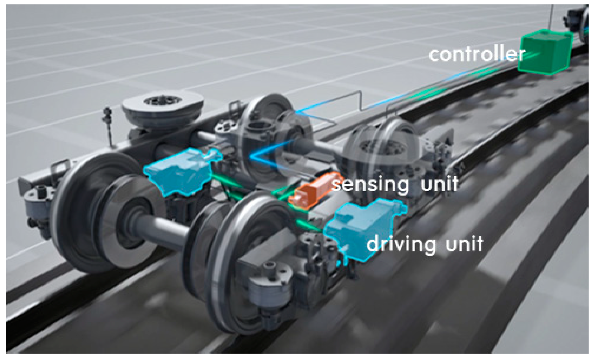
In addition, a prototype of an electro-mechanical type steering system was manufactured to be installed on an active steering bogie and performance tests were conducted on the steering system. Steering bogies equipped with steering systems were manufactured and steering control tests simulating curve running prior to the test run on the commercial line were conducted [
12].
Based on the results of the above study, Hur constructed a test EMU (Electronic Multiple Unit) train equipped with an active steering bogie and conducted steering performance tests according to active steering control on a commercial line, not on a factory line [
13]. The test results showed that the wheel lateral force was reduced by up to 86.2% compared to the conventional bogie. This result was the best of the wheel lateral force test results for the active steering bogie reported to date.
According to the results of the above study, the concept of radial steaming position control through real-time curvature radius estimation proposed by Hur was proved with simulation and a test run, and steering performance was also proved to be excellent.
In this paper, prior to the commercialization of a developed active steering bogie, we want to analyze steering performance experimentally according to the steering angle level with the aim of obtaining steering performance data to derive practical design specifications for steering system.
In other words, the maximum steering performance can be obtained by controlling the steering angle at 100% level of the target steering angle, but it is necessary to establish the practical control range in consideration of the steering system cost increase, size increase, and consumer steering performance requirements, and to commercialize this.
Therefore, an experimental study using an active steering bogie was conducted to analyze the steering performance according to the steering angle level. The steering control test was performed on a steep curve section with a radius of curvature of 300 m using an active steering bogie prototype for EMU. This study analyzes the bogie angle, wheel lateral force reduction and derailment safety under the steering angle control of the active steering bogie and describes the results.
2. Active Steering Control Strategy
When the railway vehicle runs on the curved section, attack angle between the wheel and the rail are generated as shown in
Figure 1 due to the lack of steering function of the wheel [
13]. This causes unnecessary force in the driving direction and the lateral direction of the wheel, which is a major factor causing wear of the wheels and rails and the generation of noise.
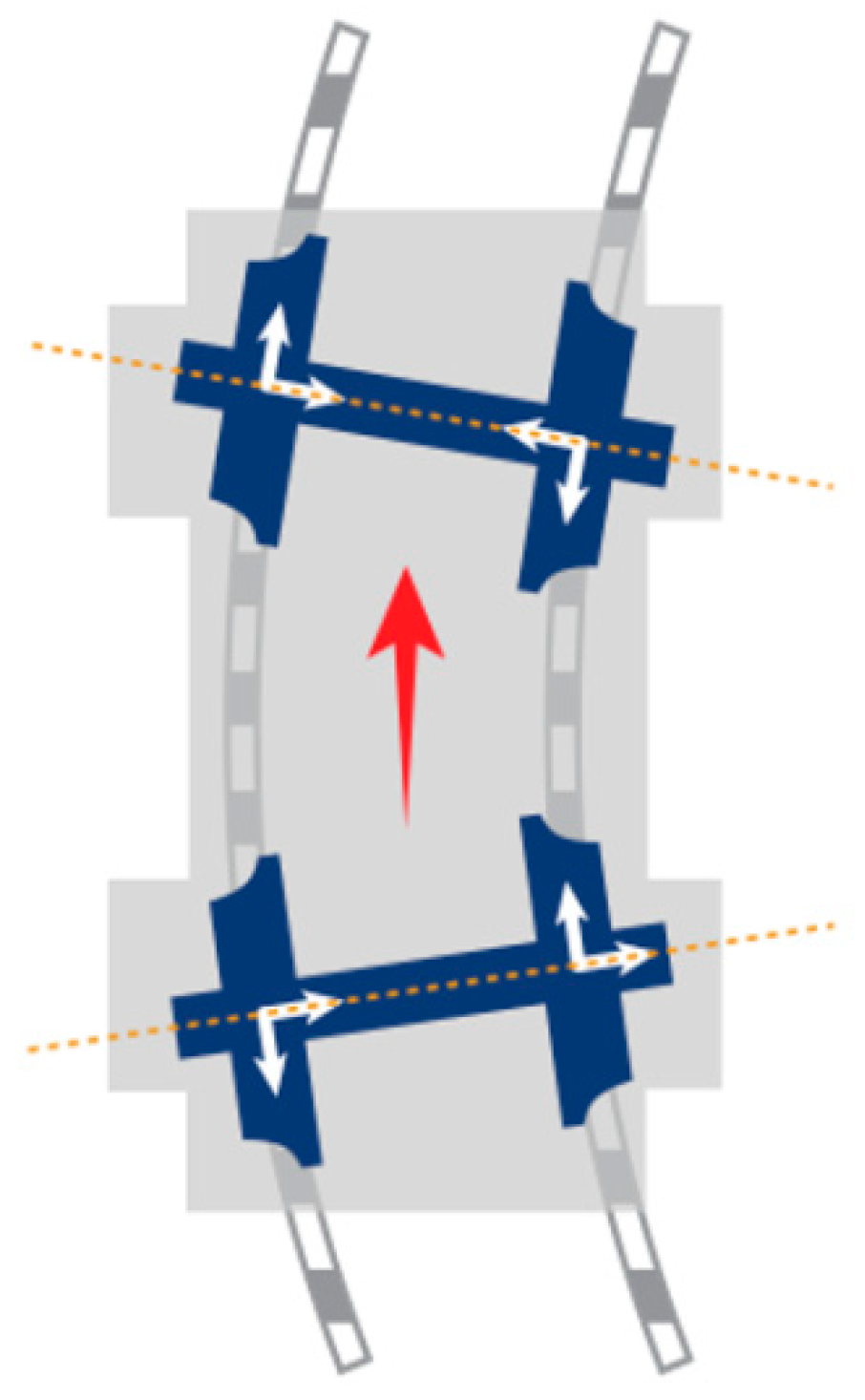
Therefore, in order for the railway vehicle smoothly run the curve section, the angle of attack becomes “0” if the wheelset is aligned with the center of curvature as shown in
Figure 2 using active steering control technology. At this time, this geometric position is called the radial steering position.
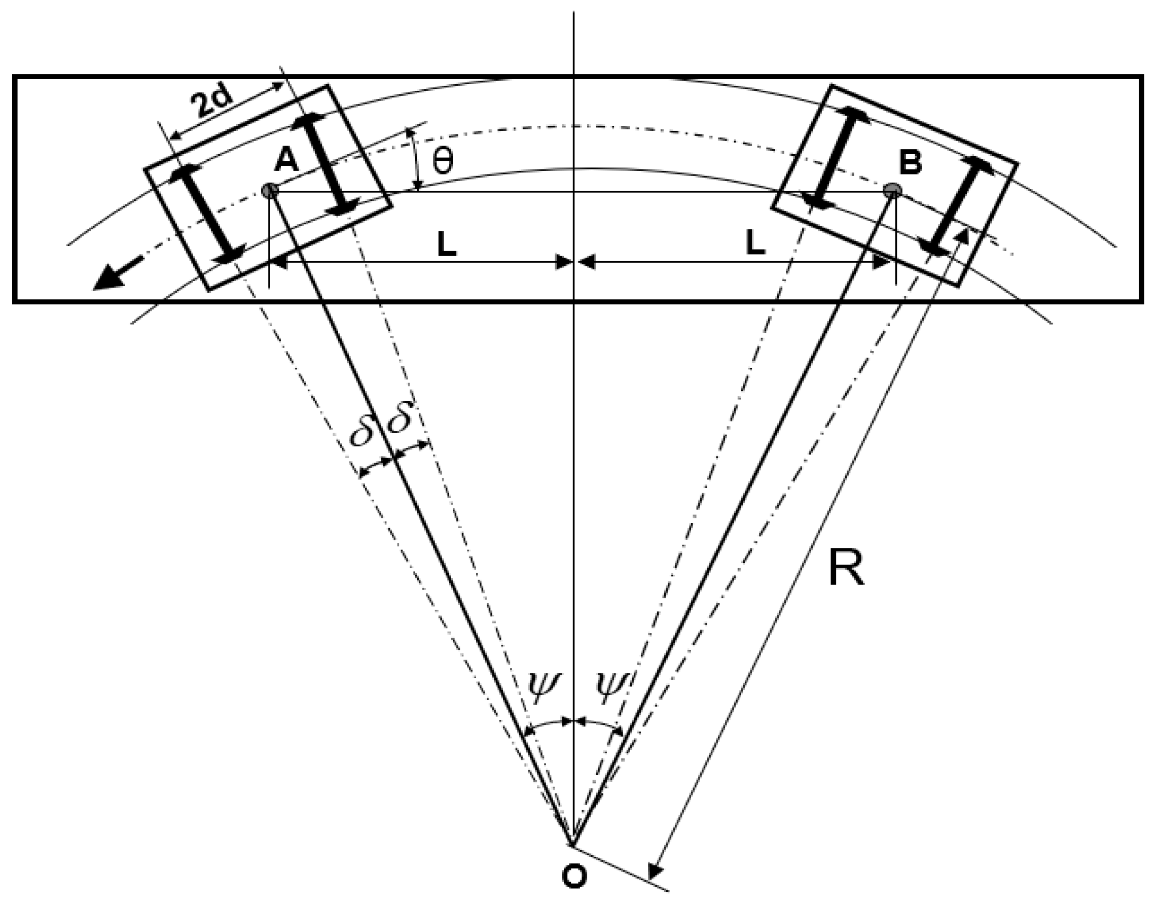
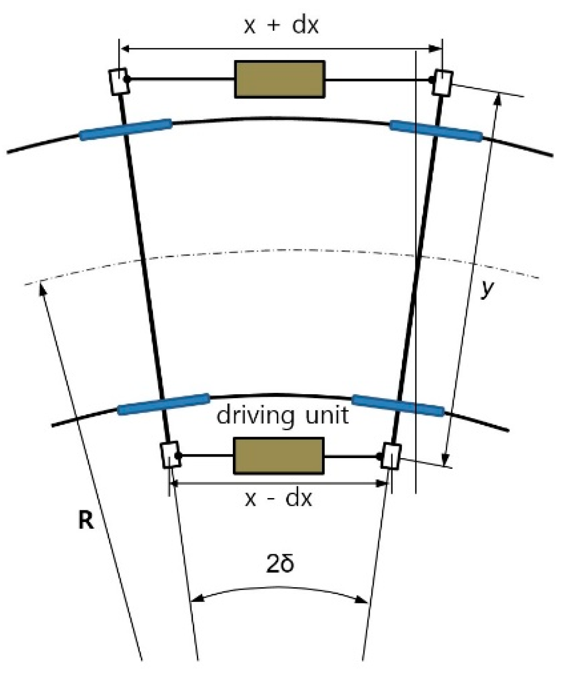
Figure 3 shows the geometrical relationship between the body and the bogies, assuming the vehicle is in the radial steering position in the curve section. In
Figure 3, the angle (2δ) formed between two wheelsets is called the steering angle, and the angle (θ) at which the bogie is rotated with respect to the vehicle body is called the bogie angle.
When the bogie and wheelset are aligned with the radial steering position, the bogie angles of the front and rear bogies are the same. At this time, from the geometric relationship of
Figure 3, the target values for wheelset steering angle and bogie angle for the ideal wheelset steering in the curve section of radius R are derived as shown in Equations (1) and (2) [
14,
15].
where,
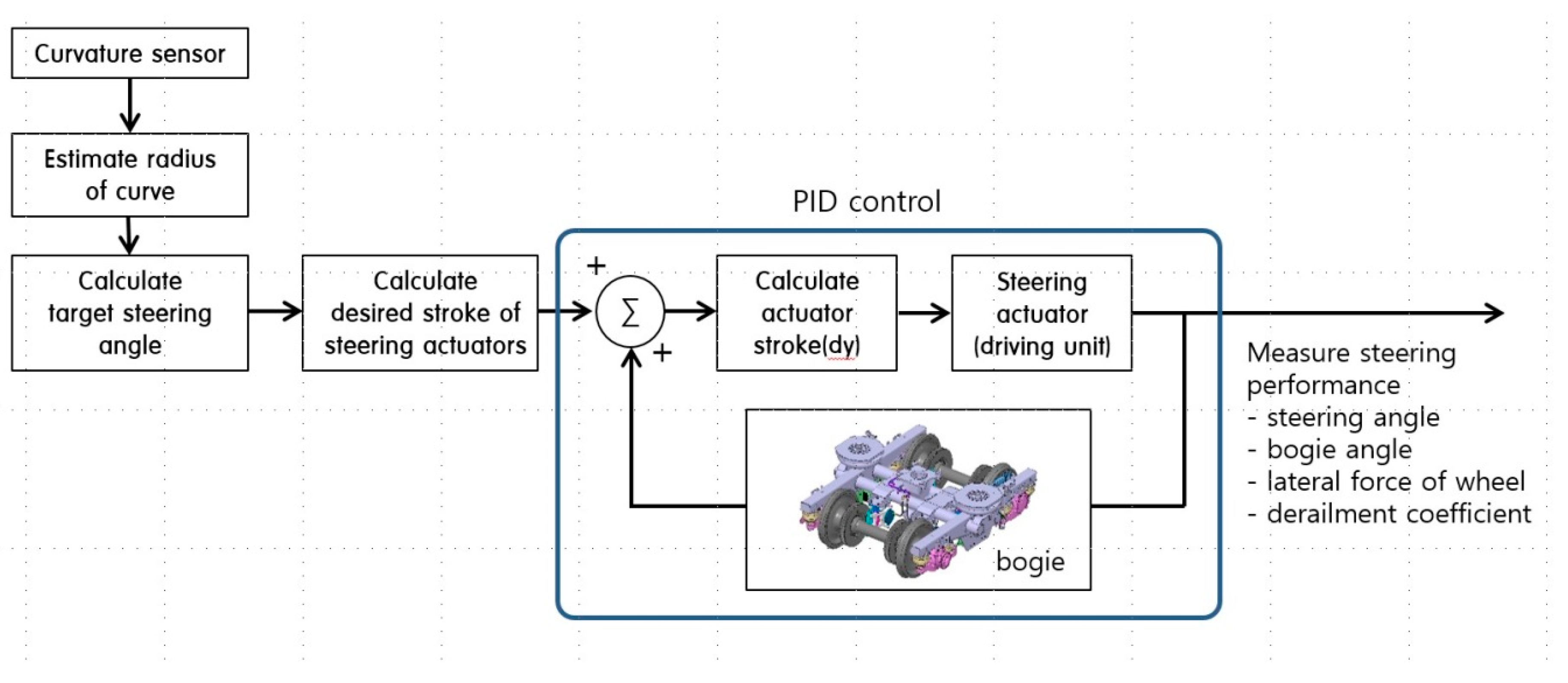
When a railway vehicle is run on a curved section as above, it can ideally pass through the curve if it is located in a radial steering position. In other words, if steering control is performed by calculating the target steering angle by applying Equation (1), the railway vehicle will be located in the radial steering position. In order to apply Equation (1), information on the radius of the curved section passing through is required. Previously, a method of pre-input of the curve information according to the position into the controller was applied, but it was inefficient. In this paper, the method of estimating the radius of curvature in real time developed by the author was used, and this method of estimating the radius of curvature was experimentally verified [
10].
4. Test Results of the Active Steering Control
4.1. Analysis Method
In order to analyze the steering performance according to the steering angle on the curved section, the bogie angle of the front and rear bogies, which are related to the radial steering position of the bogie, and the lateral force and the derailment coefficient of the wheel, which are dynamic factors, were measured.
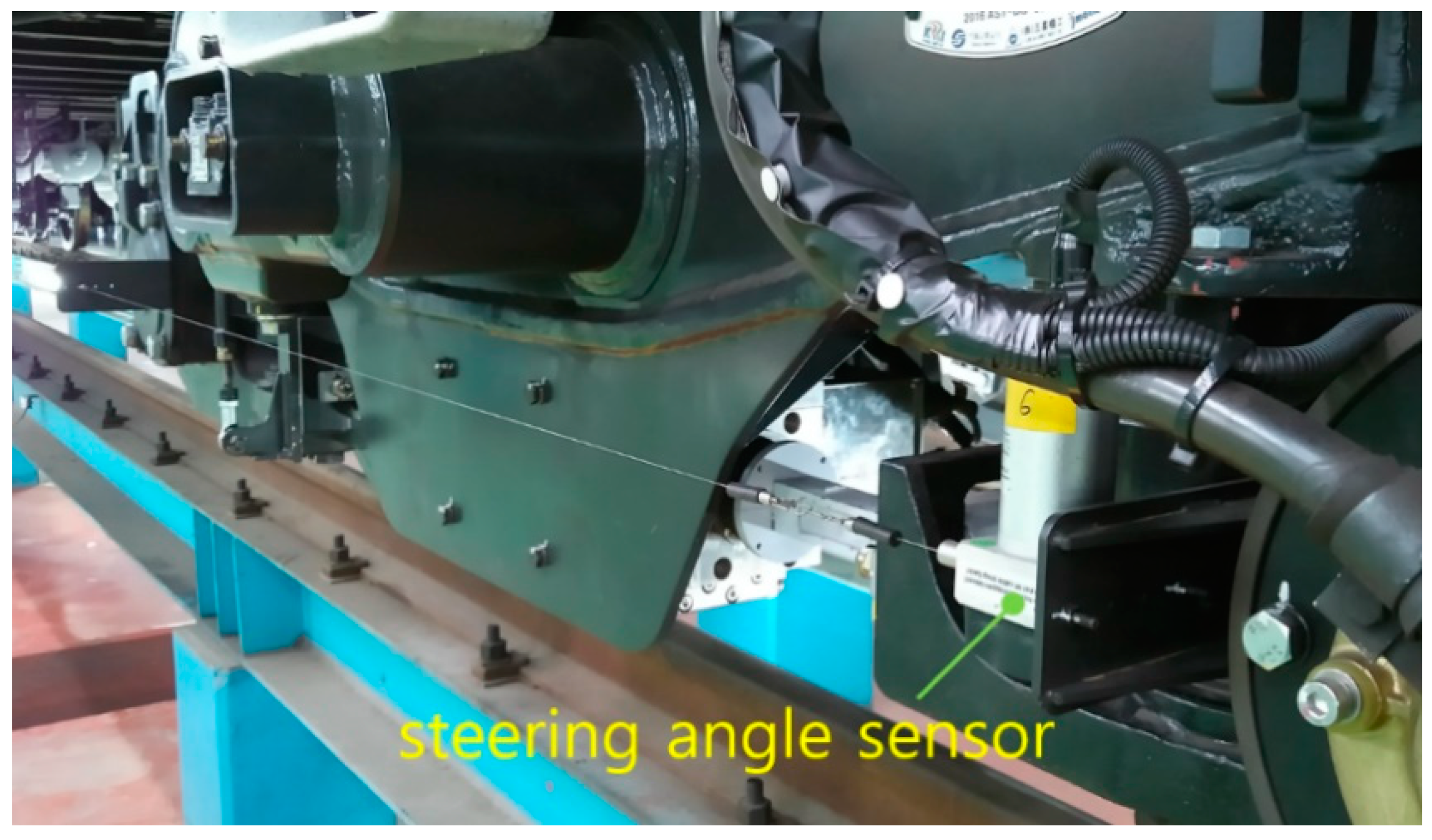
To confirm the test conditions for steering angle implementation, steering angle was measured using a steering angle sensor as shown in
Figure 9. To measure the bogie angle, which is the rotating angle between the body and the bogie, the geometric displacement between the body and the bogie was measured and converted into the bogie angle.
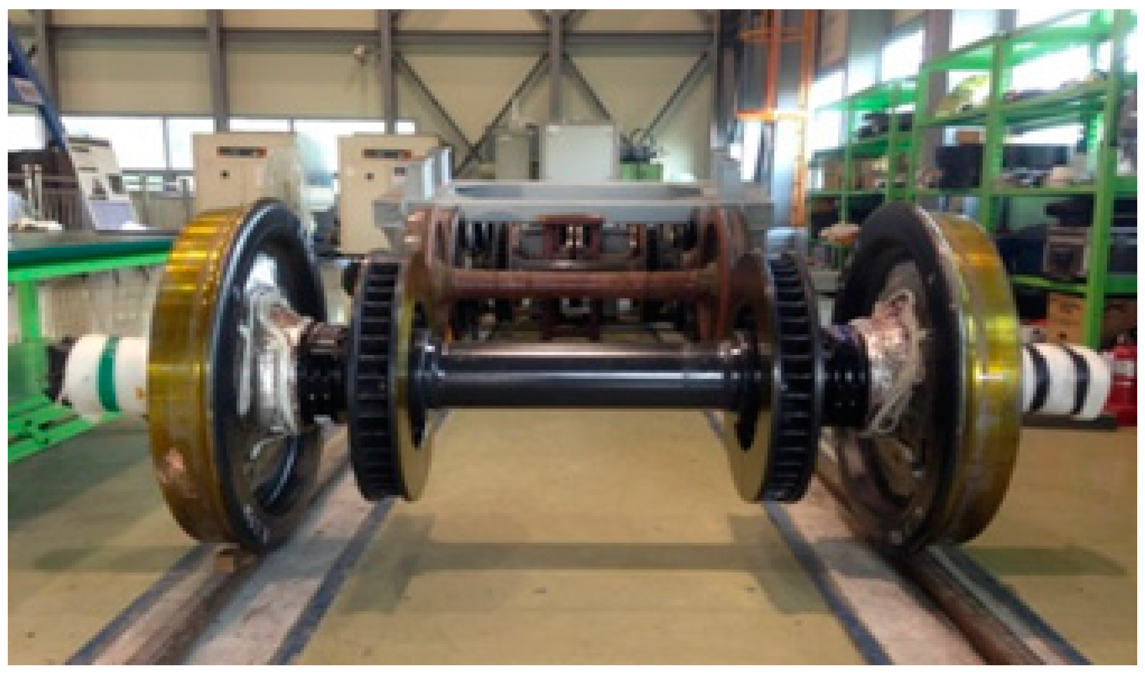
To measure the lateral force and the derailment coefficient of the wheel, a measuring wheelset was manufactured to measure the lateral and vertical force applied to the wheel and it was installed on the active steering bogie [
15].
Figure 10 shows the measuring wheelset to measure wheel forces such as wheel lateral force and derailment coefficient. The method of measuring the action force applied to the wheels of a railway vehicle proposed by Ham was used [
16].
4.2. Steering Angle
The steering control test was performed according to the test conditions in
Section 3.3 to analyze the steering performance according to the steering angle on the curved section.
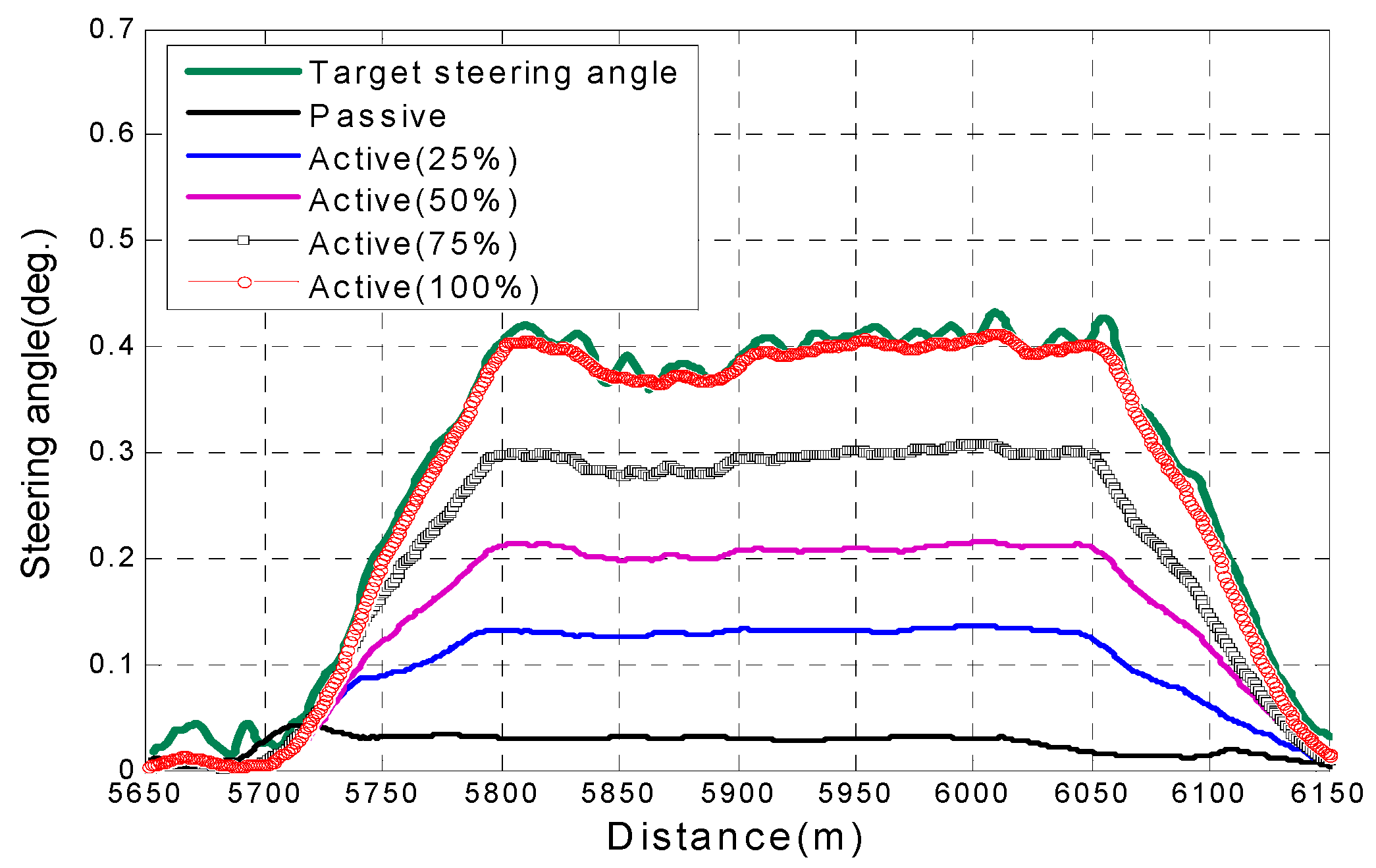
Figure 11 shows the steering angle test results measured by the steering angle sensor to verify that the active steering control test conditions are properly implemented.
Table 3 shows the mean values for the steering angles when the steering bogie runs in the circular section of the test section.
The steering angle of passive condition with insufficient steering function is 0.029 degrees. This indicates that the measured value is very low at 7.3% of the target value, considering that the target steering angle required to pass the R300 curve is 0.4 degrees according to Equation (1). As the steering angle implementation level increases with active steering control, the steering angle is approximated to the test conditions. That is, in the case of Active (50), it is 0.208 degrees., which is 52% of the target steering angle. In the case of Active (100) which performs 100% steering control, the measured value is 0.393 degrees., which is controlled well as 98.3% of the target steering angle.
4.3. Bogie Angle
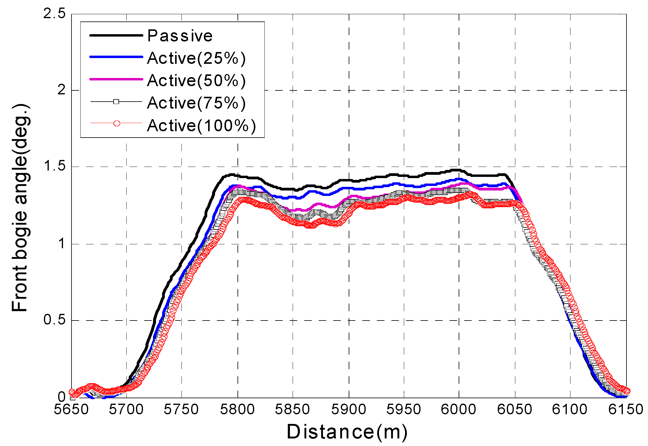
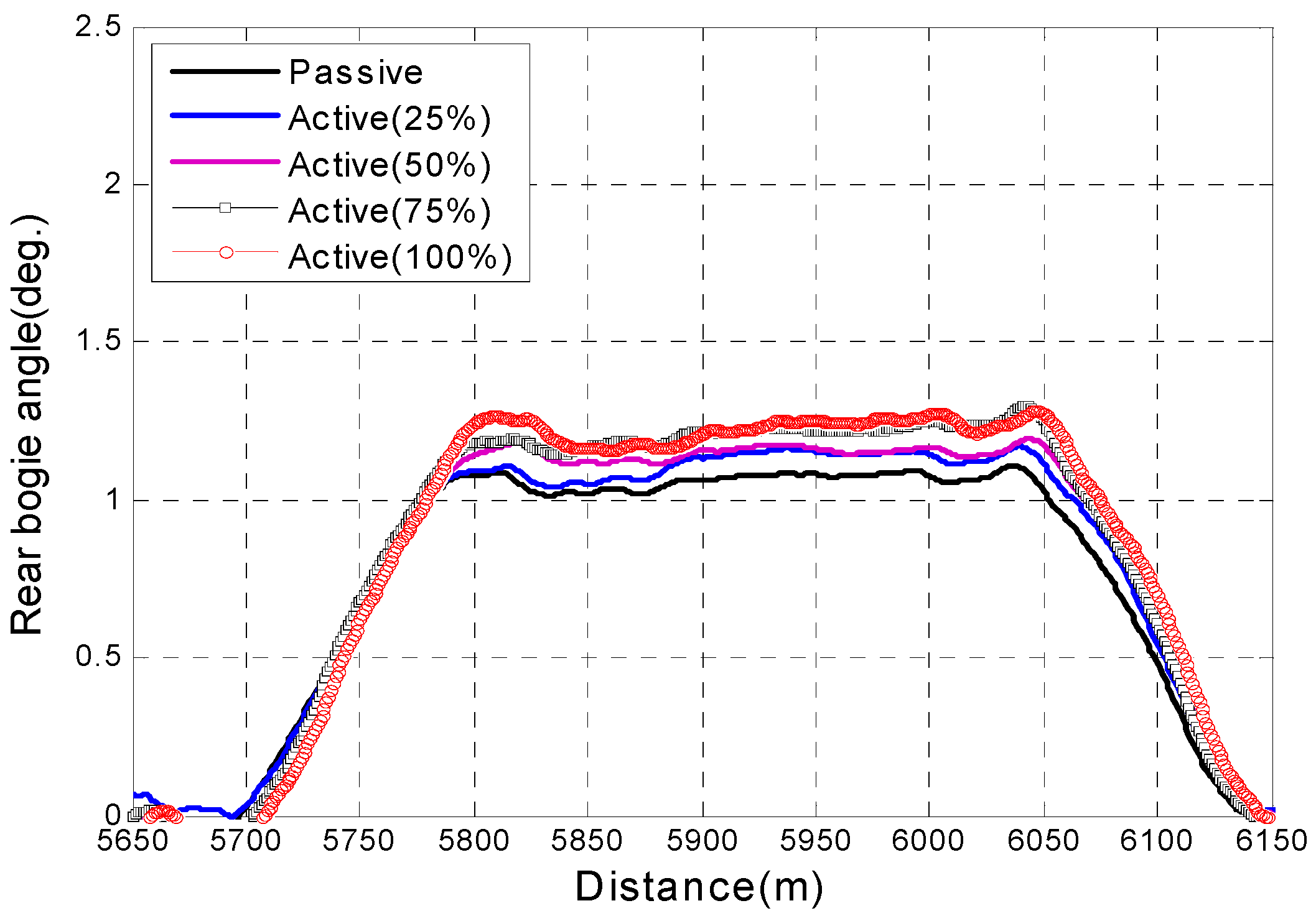
Figure 12 and
Figure 13 show the measured bogie angles generated in the front and rear bogie according to the steering angle test conditions.
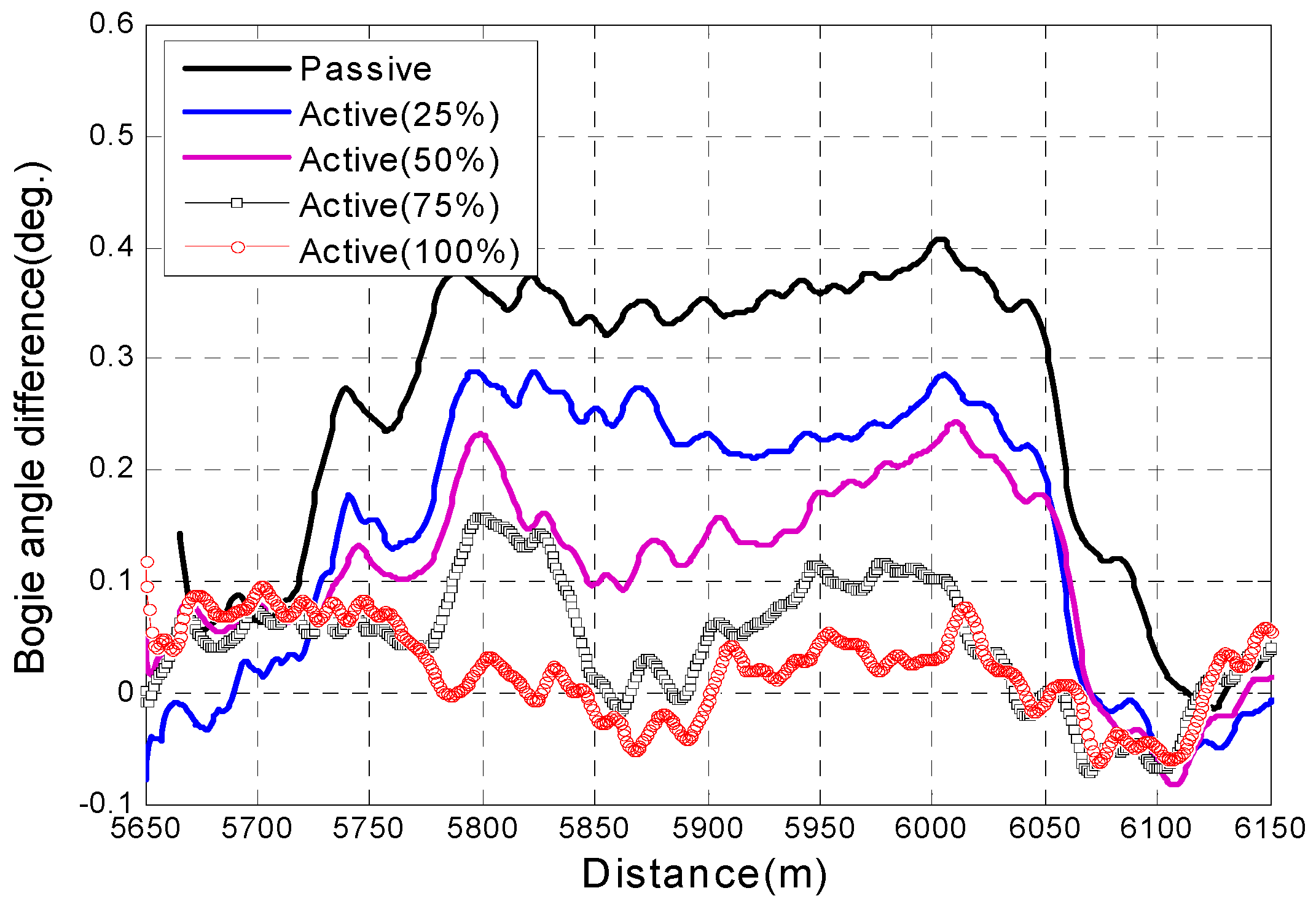
Figure 14 shows the bogie angle difference between the front and rear bogie.
Table 4 shows the mean values for the bogie angles when the steering bogie run the circular section of the test section.
In the case of a passive state with insufficient steering function, the bogie angle for the front bogie is 1.404 degrees and that for the rear bogie is 1.055 degrees and the difference is 0.349 degrees, which is very large. This result is due to the lack of steering function and the bogie is not aligned in the radial steering position when running on the curved section.
On the other hand, as the steering angle level increases with active steering control, it is shown that the bogie angle for the front bogie decreases and that for the rear bogie tends to increase. In addition, the bogie angle difference is also gradually decreasing. That is, in the case of Active (100) which performs 100% steering control, the bogie angle for the front bogie is 1.242 degrees, that for the rear bogie is 1.228 degrees, and the difference is only 0.014 degrees. This shows that the bogie is aligned in the radial position when running the curved section with active steering control.
4.4. Lateral Force of the Wheel
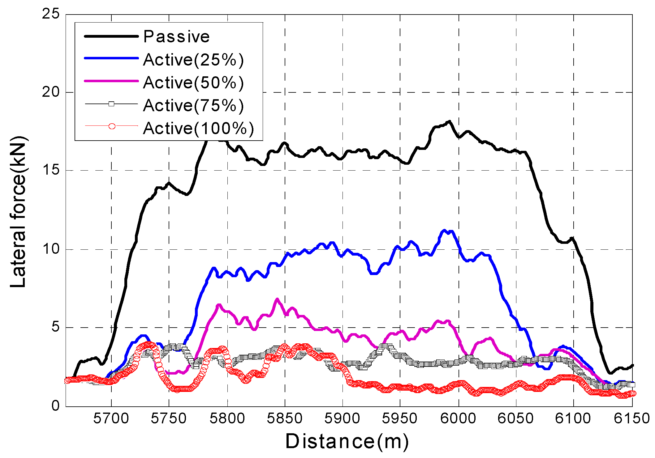
Figure 15 is test data obtained by measuring the lateral force generated on the front outer wheel of the test vehicle according to the steering angle test conditions. For lateral force analysis, UIC 518 OR “Testing and approval of railway vehicles from the point of view of their dynamic behaviour—Safety—Track fatigue—Running behaviour”, the world’s railway standard, is applied [
17]. When the test standard was applied to calculate the maximum permissible limit of wheel lateral force, the maximum permissible limit was 34 kN, and all measurement results were within the allowable limit.
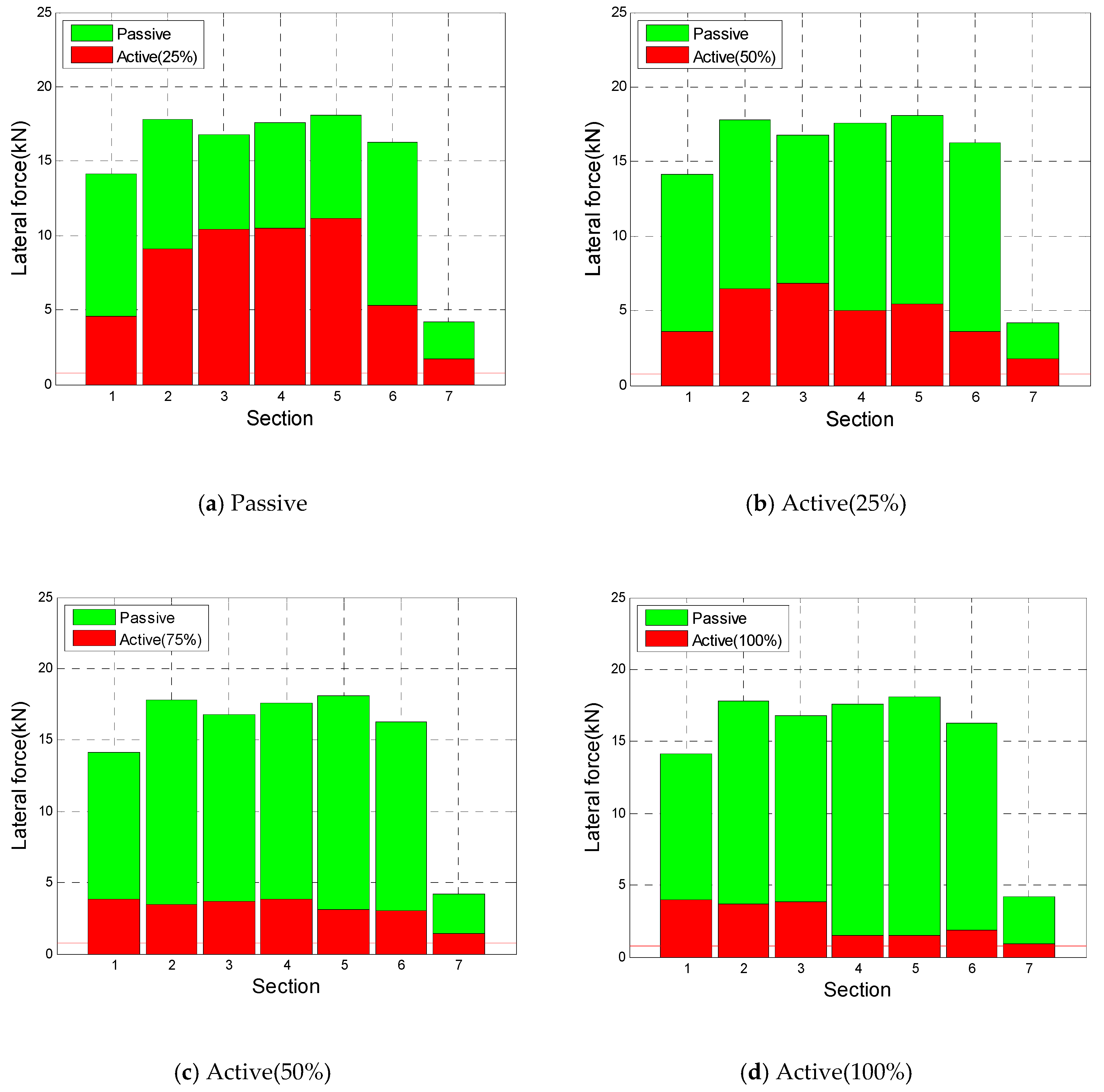
Figure 16 is the result of analyzing the lateral force test data by subdividing 70 m into small sections and arranging them in the cumulative distribution order to extract 99.85% of the values as the representative sections of the small sections.
Table 5 shows the mean values of the small section representative values for the analysis results in
Figure 15 and the reduction rate for the lateral force of each test case for the passive case.
The mean lateral force of the wheel in the passive case with insufficient steering is 14.99 kN. On the other hand, in the active steering control test condition, the wheel lateral force decreases as the steering angle implementation level increases. In the case of Active (25), it is 7.53 kN, which is 49.8% lower than the Passive case. In the case of Active (50) and Active (75), the mean lateral forces were 4.68 kN and 3.20 kN, respectively, decreasing by 68.8% and 78.6%, respectively. In the case of Active (100) with 100% steering control, the mean lateral force is 2.46 kN, which is 83.6% lower than the passive case.
Therefore, it was confirmed that the bogie was aligned with the radial position as the steering angle increased to meet the target steering angle as the test train passed through the curved section, and the wheel lateral force was also significantly reduced.
4.5. Derailment Coefficient
Derailment coefficient is a factor that indicates derailment safety when the vehicle is running and is defined as the ratio of the lateral force to the vertical force acting on the wheel.
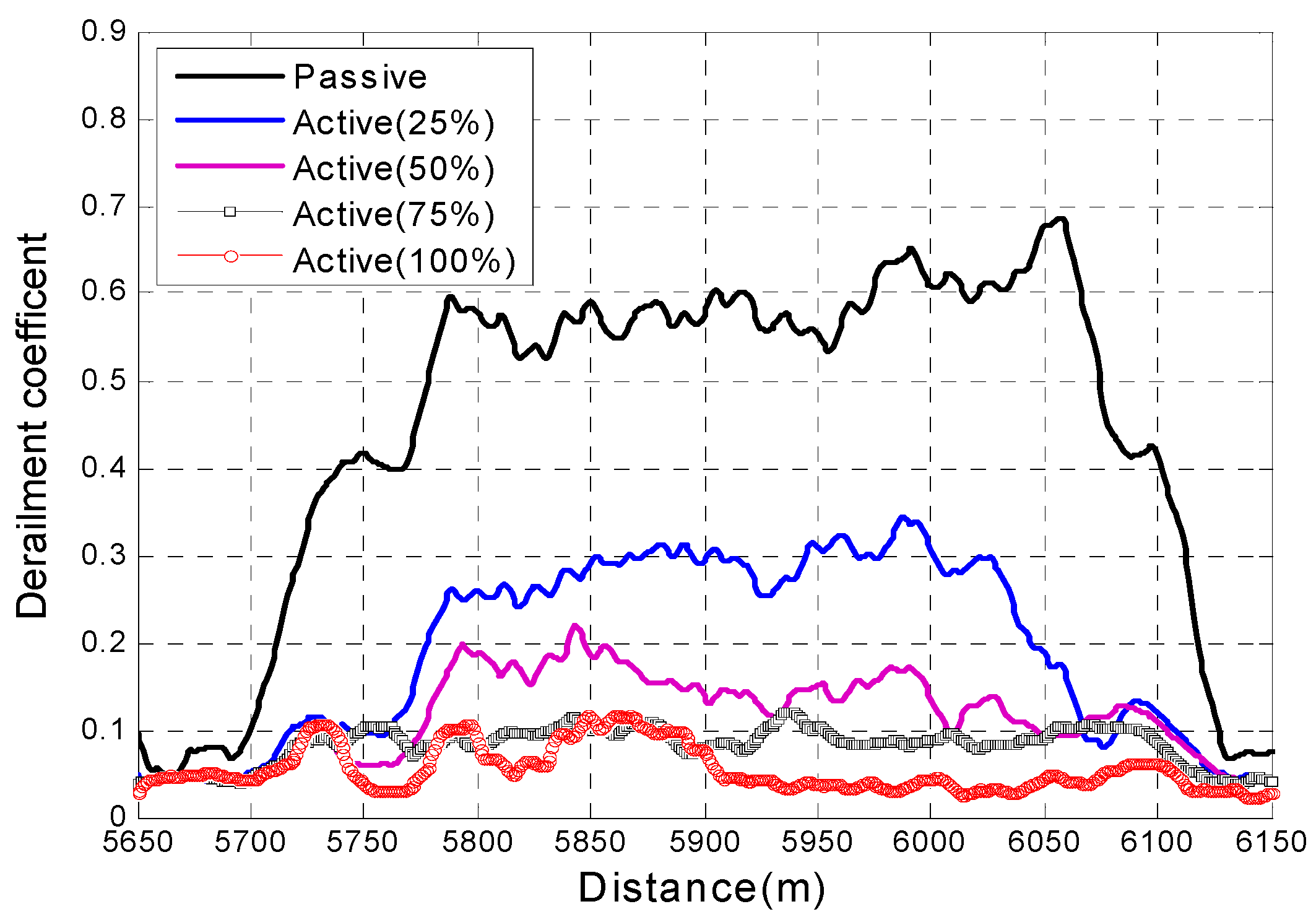
Figure 17 shows the measured derailment coefficient test data of the front outer wheel of the test vehicle according to the steering angle test conditions using the wheel force measuring wheelset.
For the analysis of the derailment coefficients, the UIC 518 OR test standard used for wheel lateral force analysis was applied [
17].
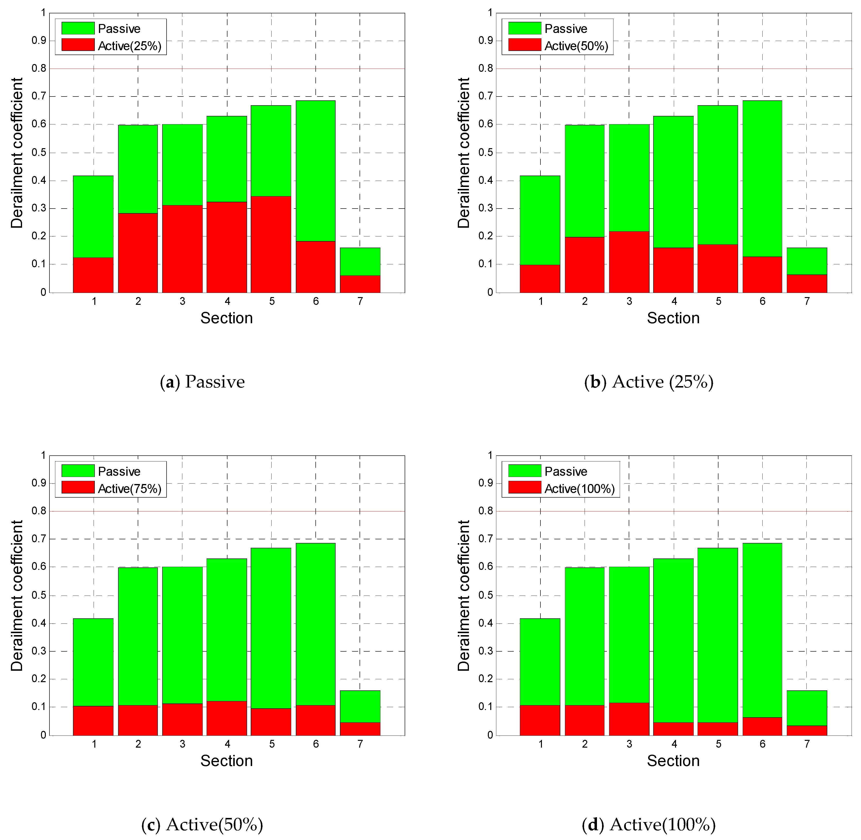
Figure 18 is the result of analyzing the derailment coefficients test data by subdividing 70 m into small sections and arranging them in the cumulative distribution order to extract 99.85% of the values as the representative sections of the small sections. Here, according to the test standard, the allowable limit of the derailment coefficient is 0.8 and all the results of the analysis are within the tolerance limit.
Table 6 shows the mean values of the small section representative values for the analysis results in
Figure 18 and the reduction rate for the derailment coefficient of each test case for the passive case.
The mean derailment coefficient of the wheel in a passive case with insufficient steering is 0.537. On the other hand, in the active steering control test condition, the derailment coefficient decreases as the steering angle implementation level increases. In the case of Active (25), the mean derailment coefficient is 0.232, which is 49.3% lower than the Passive case. In the case of Active (50) and Active (75), the mean derailment coefficients were 0.148 and 0.099, respectively, with 72.5% and 81.6% reduction rates.
In the case of active (50) and active (75), the average derailment coefficients were 0.148 and 0.099, respectively, decreasing by 72.5% and 81.6%, respectively. In the case of Active (100) with 100% steering control, the mean derailment coefficient is 0.074, which is 86.3% lower than the passive case. This means that the derailment coefficient is naturally reduced if the wheel lateral force is reduced because the derailment coefficient is the ratio of the lateral force to the vertical force of the wheel. Accordingly, it can be seen that the wheel lateral force is reduced by the active steering control and the derailment coefficient, which is a vehicle running safety evaluation factor, is also significantly reduced.
5. Conclusions
In this paper, a steering performance experiment according to steering angle level was conducted with the aim of obtaining steering performance data for the purpose of deriving practical design specifications for a steering system prior to the commercialization of an active steering bogie to be developed.
The test was carried out in a curved section with a radius of curvature of R300, and steering performance such as bogie angle, wheel lateral force, and derailment coefficient were analyzed according to the steering angle level of the active steering bogie. Here, the steering angle level was assumed to be 25%, 50%, 75%, and 100% of the target steering angle.
As a result of the test, as the steering angle was increased to match the target steering angle, the bogie angle difference between the front and rear bogies was gradually decreased. When steering control was conducted at 100% level, the bogie angles of the front and rear bogie were almost the same, and the difference was only 0.014 degrees. This means that the bogie is aligned in the radial steering position of the curved section by steering control. Wheel lateral force also tended to decrease significantly with increasing steering angle.
When steering control was performed at 25%, 50%, 75%, and 100% of the target steering angle, respectively, 49.8%, 68.8%, 78.6%, and 83.6% decreased compared to passive conditions. This means that the steering control at 100% level of the target steering angle can achieve the highest performance of 83.6% reduction in wheel lateral force, but it can be reduced to about one-half of the conventional bogie at 25% level control and about one-third at 50% level.
Considering cost rise by adopting the active steering system, this result can be used as a very important design indicator to compromise steering performance and cost rise issues in the design stage of the steering system from a viewpoint of commercialization. Therefore, it is expected that the results of the steering performance experiment according to the steering angle level in this paper will be used as very useful data for commercialization.


