Article

Design and Test of Double-Cutterbar Structure on Wide Header for Main Crop Rice Harvesting

Key Laboratory of Modern Agricultural Equipment and Technology, Ministry of Education, Jiangsu University, Zhenjiang 212013, China
*
Author to whom correspondence should be addressed.
Appl. Sci. 2020, 10(13), 4432; https://doi.org/10.3390/app10134432
Submission received: 24 May 2020 / Revised: 24 June 2020 / Accepted: 26 June 2020 / Published: 27 June 2020

Abstract

:
Harvesting main crop rice with a wide header at a required height can increase its ratoon crop yield by decreasing the stubble rolling rate. However, an increased harvest width brings in more input material in a specific time, causing the size enlargement or working speed slowdown of harvesters. To solve this issue, a double-cutterbar structure was proposed. To provide a design baseline for the structure, the cutterbar configuration methods based on rice plant deformation were developed and verified, stalk shearing tests were conducted, and a double-cutterbar prototype was fabricated and tested. The results indicated that the methods developed for the configuration of the upper and lower cutterbars could considerably implement their functions of lowering the straw-grain ratio and keeping stubble height as required. The shearing tests indicated that the bevel angle significantly influenced the total shearing energy on each cutting point in Internode 2 and 3 (p < 0.05) due to the increased stalk cross sectional area. The stubble rolling rate, panicle straw length and stubble height of the developed harvester were 26.9 %, 125 ± 80 mm and 332 ± 22 mm, respectively, which could meet the requirements of main crop rice harvesting. The outcomes indicated the functionality and practicability of the double-cutterbar structure developed based on rice plant deformation and shearing properties.

1. Introduction

The stubble after the harvesting of main crop rice can grow again and give a second production which is called ratoon crop rice. The economic advantages of rice ratooning are the low production cost, short duration and better quality, while the primary barrier to its further popularization is the low yield [1]. Though studies have reported the agronomical techniques to improve ratoon crop yield, such as variety screening, fertilizer management [2], stubble height control [3], harvest time selection [4], etc., its yield is still highly limited by the harvesting of main crop rice [5]. Currently, the main crop rice is harvested by low-efficient and expensive manpower, or by conventional harvesters with a high stubble rolling rate (40–50 %) used in single or double cropping rice [6]. A double-cutterbar harvester with a wide header is an alternative method to address this issue. When aiming to develop an efficient double-cutterbar structure for main crop rice harvesting, rice plant deformation and shearing properties should be tested and analyzed to provide the baseline for the structure configuration.
There are two requirements of main crop rice harvesting to obtain a better ratoon season yield [7]: (1) control the height of stubble (around 300–400 mm) left in the field according to the agronomic requirements, which are mainly decided by rice species and harvest time; (2) reduce the stubble rolling rate (the ratio of the width of two caterpillars to harvest width) as the nodal buds on the stubble can hardly generate rice tillers once damaged by the caterpillar.
Based on the requirements mentioned above, several main crop rice harvesters have been designed and tested. For example, Zhang et al. (2016) designed a main crop rice head spike harvester using a transplanter chassis with narrow wheels. This one-cutterbar harvester only harvests panicles with partial stalks and has a stubble rolling rate of 25.15%, but the spikes harvested must be processed additionally and the machine’s working efficiency was only 0.24 ha·h−1 [8]. Lu et al. (2017) proposed a wide header (2.55 m) harvester to reduce the stubble rolling rate during main crop rice harvesting. Though this machine reduced the rolling rate to 27.5%, its working efficiency, only 0.13 ha·h−1, could not meet the practical demand [9]. It is obvious that though widening the harvest width could directly decrease the stubble rolling rate, it also brings in more input material in a specific time, which causes the inevitable size enlargement or working speed slowdown of harvesters.
A special double-cutterbar structure shown in Figure 1 is a potential method to address the aforementioned issue. The structure comprises an upper cutterbar and a lower cutterbar. The upper cutterbar installed on the header frame can lower the straw-grain ratio by reducing the stalk length on the panicle. The function of the lower one is to cut the remain plant again to have the stubble height as required. Taking the respective advantages of the double-cutterbar structure and the wide header, it is feasible to design an efficient main crop rice harvester with low stubble rolling rate.
To implement the functions of the two cutterbars, it is necessary to configurate the cutterbars according to the rice plant deformation during harvesting. In the past, plenty of studies were carried out on the measurement of stalk crop deformation calculation properties. İnce et al. (2004) calculated the bending stress and the modulus of elasticity of sunflower stalks using the bending forces measured by a cantilever test in the field [10]. Esehaghbeygi et al. (2009) measured the bending stress and modulus of elasticity of wheat stem and found these parameters increased as the moisture content decreased and decreased as the cutting height of stem increased [11]. Chattopadhyay and Pandey (1998) studied the bending properties of sorghum stalks under quasi-static deformation at different growing stage using a universal testing machine [12]. However, the measurements of these parameters were complicated, and the separated results obtained were difficult to apply in deformation calculation. To simplify the calculation, an easier method is to directly use the flexural rigidity (EI), the product of the modulus of elasticity and moment of inertia. Inoue et al. (1998) calculated the flexural rigidity of a rice stalk through deflection deformation experiments and substituted it into a large deflection formula to fit the deformed curve [13]. Furthermore, Hirai et al. proposed a bending model of rice stalks based on formula deduction and empirical data [14]. Huang et al. (2019) deduced a numerical calculation method for deflection deformation of rice stalk [15]. However, the above methods can only be used for rice stalks calculation. Therefore, assumptions that the rice plant is bent elastically and the panicle is moved translationally during harvesting were made in this paper to calculate the deformation of the whole rice crop.
The shearing bevel angle is an important factor affecting cutterbar working efficiency. Since the heights of both cutterbars are subject to the harvesting conditions and requirements, it is necessary to investigate the influence of shearing bevel angle on shearing properties within whole range of rice stalk. So far, plenty of studies have reported various shearing properties of rice crops. Alizadeh and Habibi (2016) found that the cutting energy of rice stems in the second internode decreased by an average of 32.5% compared to third internode [16]; Allameh and Alizadeh (2016) reported that rice cultivar and blade velocity had significant effects (p < 0.01) on the specific cutting energy, and blade cutting and bevel angles were not solely influential on the specific cutting energy but they interacted with rice cultivar and impacted it [17]; Tabatabaei and Borgheei (2006) found that the static and dynamic shearing strength was different among varieties, and blade bevel angle and blade type had no significant effect on the shearing strength [18]. However, these studies only focus on limited areas of rice stalk. To provide comprehensive information for multi-cutterbar bevel angle configuration, a series of rice stalk shearing tests using three shearing bevel angles (0°, 15°, 30°) were conducted within whole range of rice stalk (15 cutting positions) in this study.
The primary goal of this study was to develop a double-cutterbar structure designed based on rice plant deformation and shearing properties for a wide header to solve the problem of main crop rice harvesting. The detailed objectives are to: (1) develop and verify configuration methods for upper and lower cutterbars; (2) study the influence of cutterbar bevel angle on shearing properties within whole range of rice stalk; and (3) fabricate and test the double-cutterbar prototype to validate its functionality and practicability.

2. Materials and Methods

2.1. Double-Cutterbar Configuration Methods

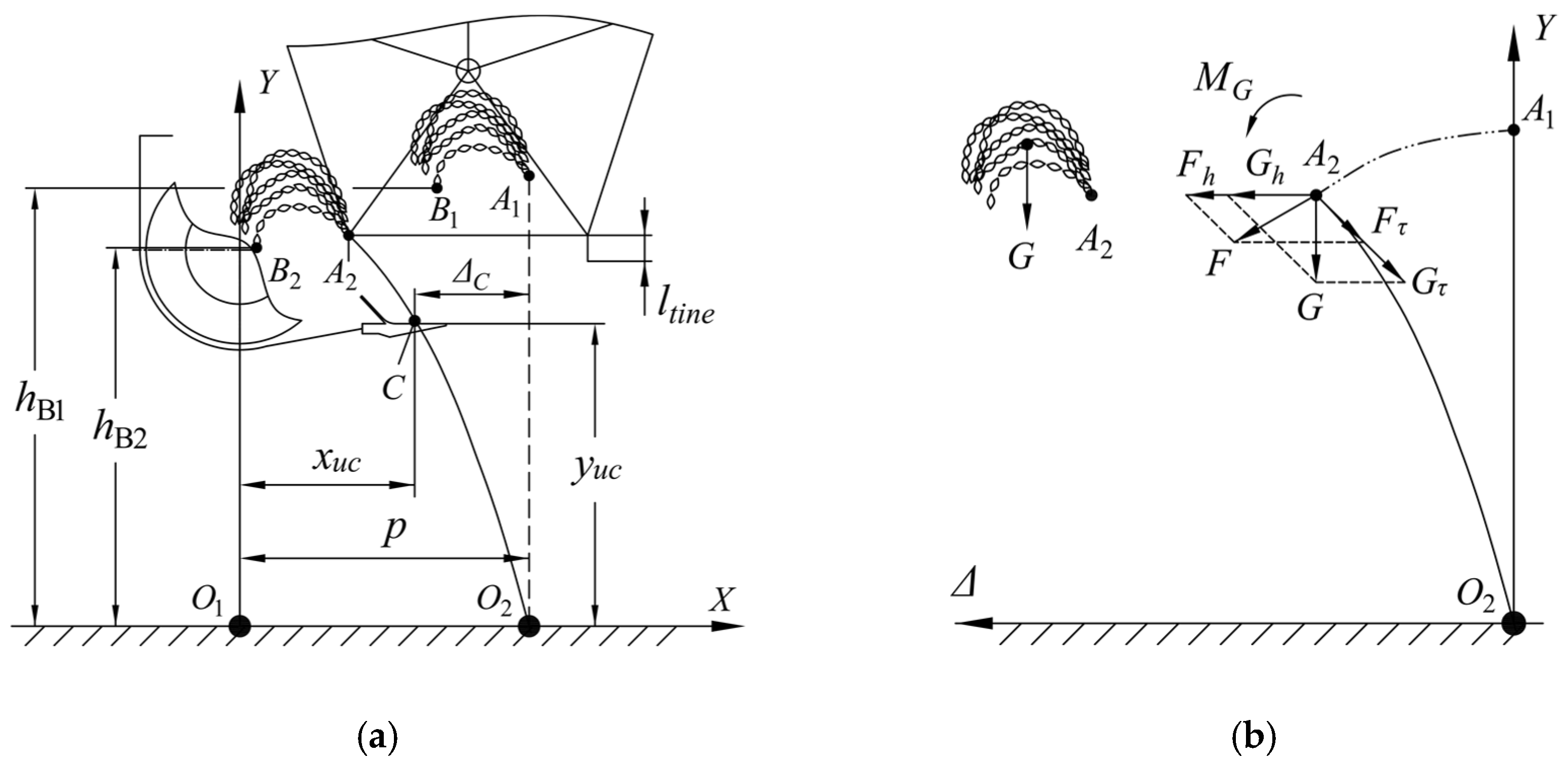
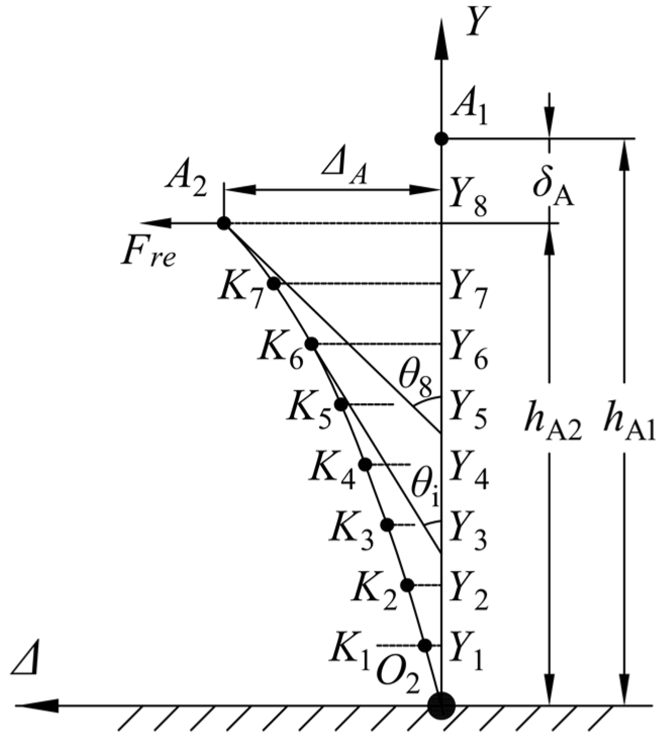
2.1.1. Upper Cutterbar Configuration Method Based on Rice Crop Deformation

As shown in Figure 2a, the panicle should be cut off before the reel bar, leaving the connection joint of panicle and stalk (point A2) to support the cutting process of stalks by the upper cutterbar [19]. Moreover, to ensure all panicles are harvested with less stalks, the cutterbar should be set under the lowest point of the panicle of the deformed crop (point B2) and be as close to it as possible. To describe the cutterbar configuration, a coordinate system XO1Y was established.
To calculate the deformation of the whole rice crop, the assumptions that the plant is bent elastically by the reel and the panicle is moved translationally were made. To facilitate the calculation, another coordinate system ΔO2Y describing the rice crop deformation was established. The force analysis of the rice crop bent to O2A2 is illustrated in Figure 2b. The forces acting on the crop include the force F exerted by the reel and the weight of the panicle G, which are acted on point A2 and the center of the panicle, respectively. The weight G can be moved to point A2 with an additional torque (MG). Furthermore, F and G can be decomposed into horizontal forces Fh, Gh and tangential forces Fτ, Gτ. The tangential forces give the elongation on the surface of the stalk at point A2, but the effect on the bending is considered to be very slight [20]. Thus, the tangential forces are neglected in the deformation calculation. The torque MG can be transformed to a horizontal force FM acting at point A2. Therefore, the resultant force at point A2 can be presented as follow:
F r e = F h + G h + F M
The curve of the stalk O2A2 as shown in Figure 3 can be fitted by substituting Fre into Equation (2), the large deflection formula [13], which can be solved by the fourth-order Runge–Kutta method [13,16].
d Δ d y = h A 1 · y y 2 2 ( E I F r e ) 2 ( h A 1 · y y 2 2 ) 2
where, Δ is the deflection of the stalk, mm; y is the vertical coordinate of the stalk, mm; EI is the flexural rigidity of stalk, N·mm2.
To obtain the values of Fre and EI, rice stalk deflection experiments detailed by Huang et al. were conducted and the vertical and horizontal displacement of point A can be calculated by Equations (3) and (4) [15]. In the calculation of EI, the rice stalk was partitioned into eight equal segments on vertical according to the Simpson’s Formula, as shown in Figure 3; the angle between tangent line of point Ki and Y axes can be presented as Equation (5) [15].
Δ A = 0 h A δ A sin θ 1 sin 2 θ d y
δ A = h A 2 E I F r e sin θ A
θ i = arcsin ( F r e ( h A 1 δ A ) 2 2 E I F r e ( h A 1 δ A y i ) 2 2 E I ) ( i = 1 , 2 , , 8 )
Suppose the height of the panicle lowest point before bending is hB1; then, according to the assumption that the panicle is only translationally moved, the height of the point can be presented as:
h B 2 = h B 1 δ A
Take the reel tine into consideration, the height of the upper cutterbar can be designed as:
y u c = min ( h t i n e , h B 2 ) a
where, a is an offset value for yuc, 30 mm ≤ a ≤ 50 mm.
Once the yuc was determined, its horizontal position ΔC in the coordinate system ΔO2Y can also be obtained on the fitted curve of the rice stalk through Equation (2); then, xuc can be calculated:
x u c = p Δ C

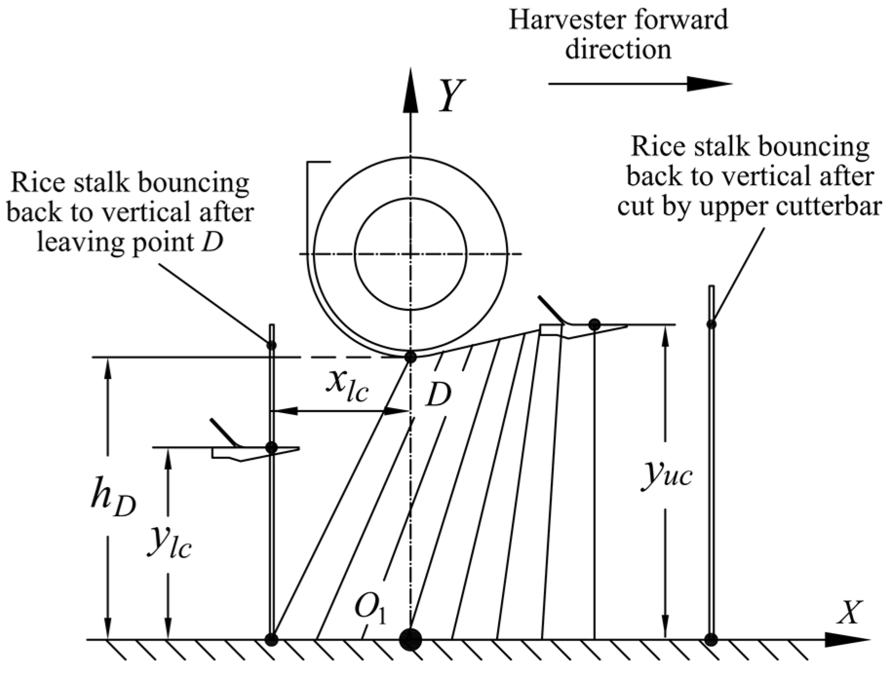
2.1.2. Lower Cutterbar Configuration Method

The position of the lower cutterbar is critical to keep the stubble as required. As shown in Figure 4, the rice crop bounces back to vertical status after cut by the upper cutterbar and it will be cut by the upper cutterbar at the height of yuc again with harvester moving forward. Due to the lowest point of the header frame is lower than the upper cutterbar, the crop will be continuously inclined until it leaves point D and returns to its upright position again. Therefore, an easier configuration method for the lower cutterbar is to set it behind point D and to cut the stalk after it leaves point D and returns to upright position. By doing so, ylc is equal to the required stubble height and xlc is the horizontal displacement of the stalk endpoint when it leaves point D. Due to the stalk has been largely shortened by the upper cutterbar, an assumption that the stalk inclined under the header frame bottom is a rigid straight line was made. Thus, the xlc can be presented as:
x l c = y u c 2 h D 2

2.1.3. Bending Experiment

To validate the feasibility of the methods mentioned in last two sections, a series of bending experiments were conducted. Rice variety Y-Liangyou-911, planted in Liuyang (location: 28.299230°N, 113.410280°W), Changsha, Hunan province of China, was used as the test material. In August 2018, rice plant samples were randomly chosen and manually cut by a sickle at the ground-level. In the same day, plants collected were transported to Key Laboratory of Modern Agricultural Equipment and Technology, Ministry of Education, Jiangsu University, Zhenjiang, China. A total of 30 rice plants were randomly chose in the experiment. The material preparation and experimental methods were detailed by Huang et al. (2019) [15], and the experiment procedures are shown as follow:
(1)
Deform rice plant with a horizontal force on the point A to a designed deflection value ΔA;
(2)
Measure the actual curve of stalk and panicle lowest point;
(3)
Cut off the panicle and record the horizontal force Fre using a digital force meter;
(4)
Cut the stalk again at the height of 570 mm, which is a maximum value for yuc, and incline the stalk until the vertical height of stalk endpoint decreasing to hD;
(5)
Measured the actual curve of the stalk.

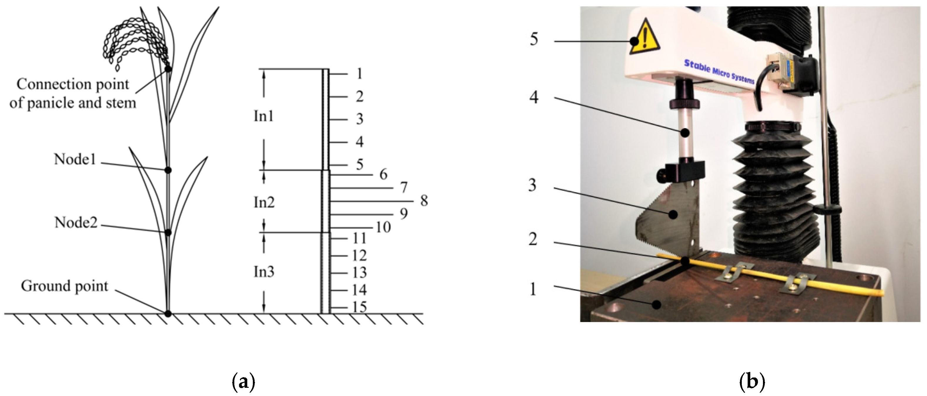
2.2. Shearing Tests within Whole Range of Rice Stalk

The material used in the shearing tests was from the same batch of rice plants used in the deformation tests. Prior to the tests, rice stalks were divided into three internodes, namely In1, In2 and In3, according to node distribution (Figure 5a). Each internode was evenly marked with five cutting position, and they were numbered from 1 to 15 from the top to the bottom of the stalk. In this experiment, rice stalks were cut by a cutterbar blade (Ledger plate III, World Agricultural Machinery Co., Ltd., Jiangsu, China) and there were 15 cutting positions and three levels of shearing bevel angles (0°, 15°, 30°). The experimental data were recorded for maximum shearing force (Fτmax) and total shearing energy (Es) of each cut using a texture analyzer (TA; XPplus, Stable Micro System, UK). All cuts were carried out at a quasi-static shearing speed of 20 mm·min−1 (İnce et al., 2005) on the shearing rig shown in Figure 5b [10]. Ten replications each for three shearing bevel angles (0°, 15°, 30°) at a same cutting position were prepared. Statistical procedure of multiple ANOVA using OriginLab2018 was performed to determine the effect of shearing bevel angle on the Fτmax and Es at each cutting point.

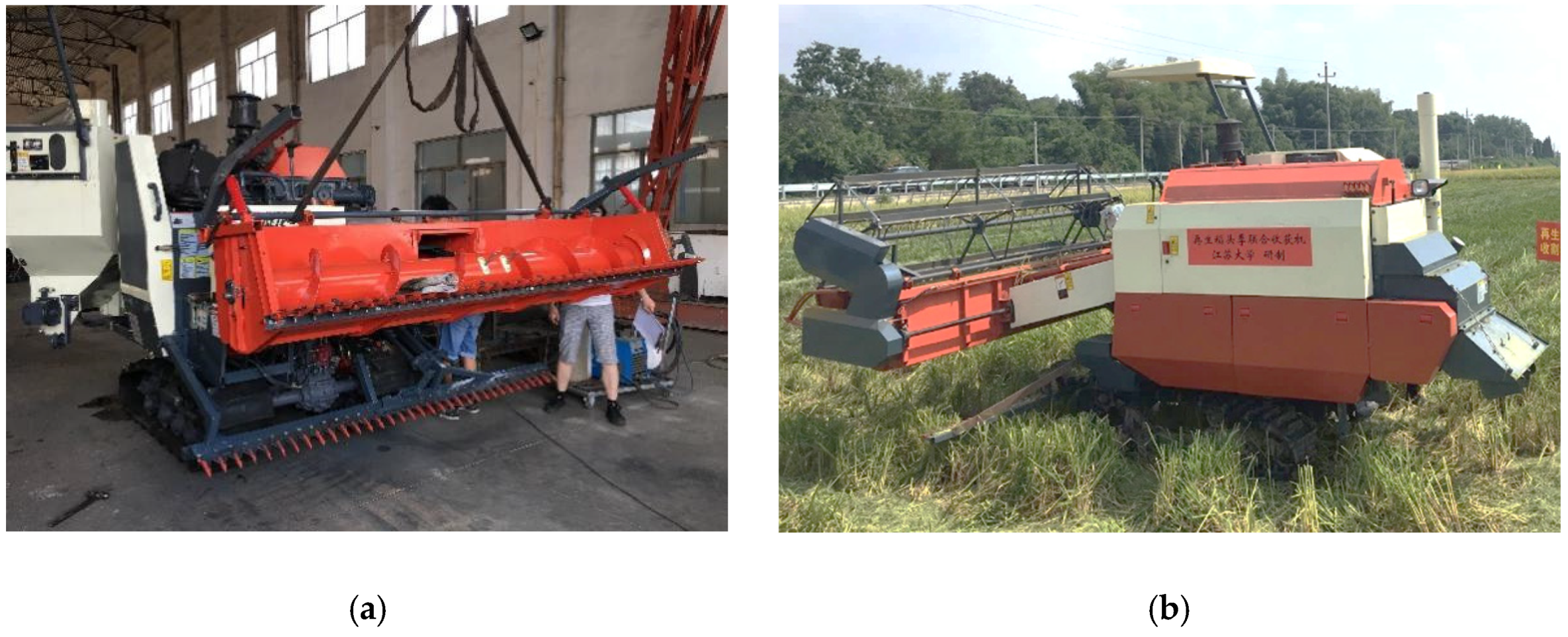
2.3. Prototype Development and Field Test

To evaluate the functionality and practicability of the double-cutterbar structure, a prototype was fabricated with a 2.6 m wide header based on rice plant deformation and shearing properties. The prototype was mounted onto a walking chassis of World 4LZ-3.0E combine harvester, as shown in Figure 6a,b, and its basic parameters are listed in Table 1.
On 13–15 August 2019, the field test was carried out at the same place where the deformation and shearing test material were sampled in 2018. Three adjacent fields were used as repetitions of the tests and their areas were 0.65, 0.71, 0.51 ha, respectively. The rice growing procedure used was identical in the three fields in 2018 and 2019. The average heights of the rice in 2018 and 2019 were 886 ± 33 mm and 875 ± 41 mm (values presented as mean ± standard deviation), respectively, and the required stubble heights were both 350 mm. Five parameters were selected as the performance indexes and their computing methods are shown as follow:
(1)
Stubble rolling rate:
R = 1 3 A r i A a l l · 100 %
where, R is stubble rolling rate, %; Ari is stubble rolling area in each testing filed, ha; Aall is total area of the three fields, ha.
(2)
Panicle straw length: stop the harvester three times and collect 50 panicles from the header at each time. Measure and average the lengths of the stalk on panicle of all samples:
L a = 1 150 L i 150
where, La is panicle average straw length, mm; Li is panicle straw length on a single sample, mm.
(3)
Stubble height: randomly choose three spots in the test field after harvesting and select 50 stubbles at each spot. Measure and average the heights of all samples.
H a = 1 150 H i 150
where, Ha is stubble average height, mm; Hi is stubble height of a single sample, mm.
(4)
Feeding rate:
Q = W v t
where, Q is feeding rate, kg·s−1; Wv is total weight of grain harvested and discharges from cleaning parts in a time of t, kg.
(5)
Working efficiency:
E w = A a l l T
where, Ew is working efficiency, ha·h−1; T is total time consumed in harvesting of the three fields, h.

3. Results and Discussion

3.1. Verification Analysis of Double-Cutterbar Configuration Methods

An example of the fitted curves of rice plant before cut by upper cutterbar, rice stalk before cut by lower cutterbar, fitted point of the panicle lowest point, and their corresponding measured values of a single plant is shown in Figure 7. The results showed that the fitted curve of stalk before cut by the upper cutterbar was close to the measured one, with the free end error and the maximum error being only 5.8% and 8.6%. The predicted panicle lowest point was also close to the actual one, with the horizontal and vertical error being only 4.3% and 1.75%. This suggests that the calculation methods used could provide considerable accuracy in the upper cutterbar configuration. On the other hand, the measured curve of the stalk before cut by the lower cutterbar was compared to an inclined straight line with the error between the two endpoints being 5.9 %. It was indicated that using Equation (9) would obtain a xlc that was a bit larger than the actual value of stalk endpoint displacement, while this could be beneficial to the stalk cutting of the lower cutterbar by providing more space between stalk and cutterbar. Therefore, the methods developed for the configuration of the upper and lower cutterbars could considerably implement their functions of lowering the straw-grain ratio and keeping stubble height as required.
The deformation calculation methods developed can be applied to other stalk crops, such as wheat, oat, sorghum, and sunflower, etc. However, the parameters used in calculation should be collected and calculated prior to harvesting operations, which could be time-consuming, and the results obtained can only be used to one specific variety. As the mechanical properties of a crop may differ from variety to variety, one database of their deformation properties could be established to provide baseline information for the design of harvesting machines.

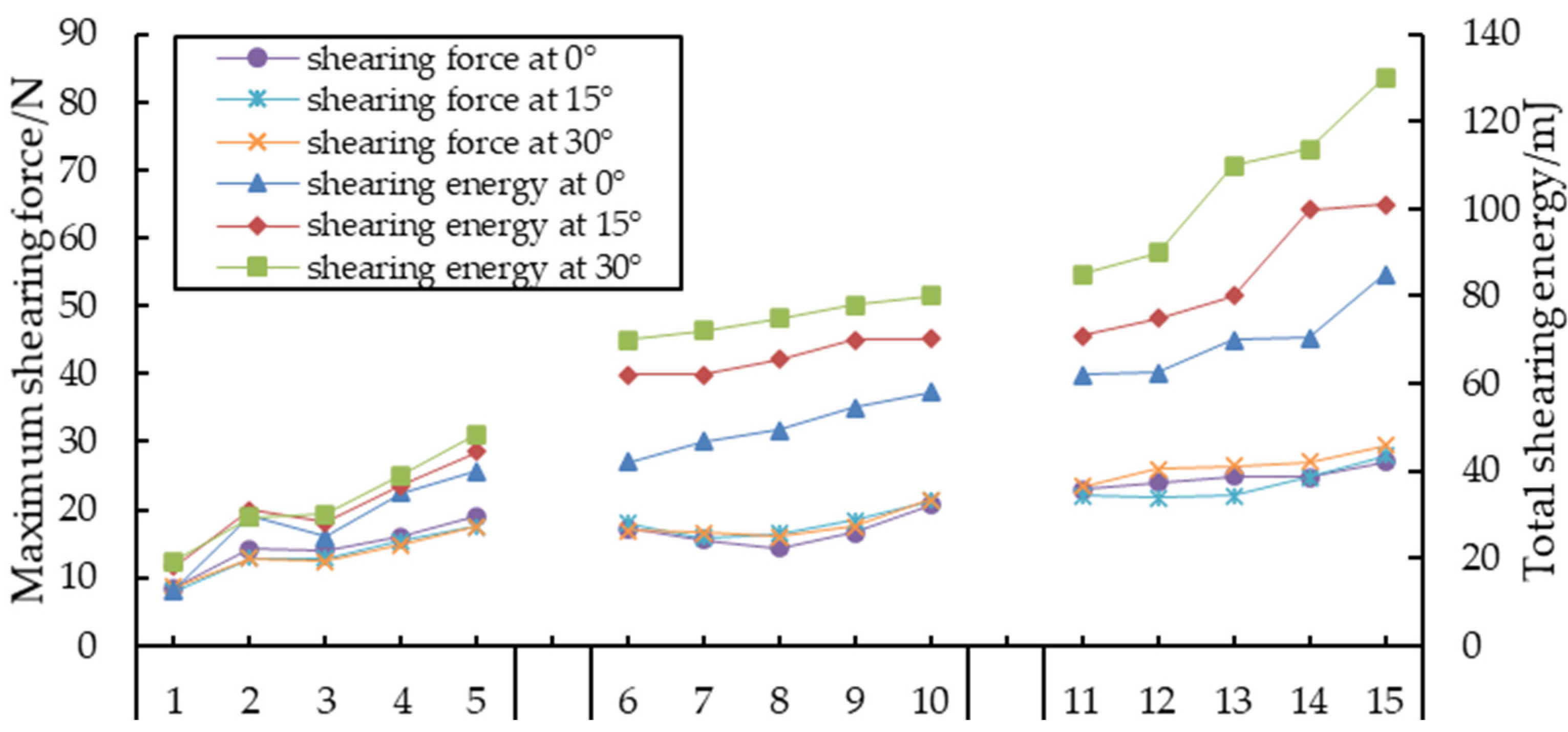
3.2. Results of Shearing Tests and Analysis

Figure 8 presents the changes of maximum shearing energy consumed and maximum force used in stalk cutting at 15 different cutting points with three differed angles. From the aspect of shearing force, the values of 0° increased from 8.5 ± 5.9 N to 19.0 ± 3.5 N, from 23.0 ± 3.1 N to 27.0 ± 6.8 N in In1 and In3, and the values decreased to 14.3 ± 2.4 N from 17.3 ± 3.5 N and increased to 20.7 ± 1.7 N in In2. The same variation pattern could be observed in the cuts of 15° and 30°, that is the maximum shearing forces steadily increased as cutting position moving from the top down in In1 and In3, and slightly dropped before rose again in In2. The reason for this trend is that In1 and In3 are both tapered with a narrow top and a wide bottom and In2 is a long cylinder with a hollow inside [17]. As shown in Table 2, it was found that that the cutting angle did not significantly influence the maximum shearing force at any cutting point (p < 0.05). This indicated that in the cutterbar configuration bevel angle would not affect its maximum shearing force.
From total shearing energy, it was clear that in each internode the energy consumption increased as cutting point moving towards the bottom of the crop, while the growing speed was faster in In1 and In3 than in In2. For example, the shearing energy of 0° increased from 12.6 ± 2.8 mJ to 40.0 ± 25.2 mJ, from 42.0 ± 22.6 mJ to 58.8 ± 3.7 mJ and from 62.2 ± 13.0 mJ to 85.0 ± 19.3 mJ in In1, In2 and In3, respectively. Again, this was related to the structure of each internode. Moreover, the significance analysis in Table 2 showed that different cutting angle had obvious influence on the total shearing energy in In2 and In3, but not in In1 (p < 0.05). Also, the shearing energy was greater with larger shearing angle. The reason for this was that stalk cross sectional area of In2 and In3 grew faster than of In1 with increased bevel angle. As the rice plant is largely deformed when cut by upper cutterbar, it is evident that different shearing angle can have a direct impact on energy consumption. Thus, in the configuration of the cutterbar, it is necessary to adjust bevel angle according to rice plant deformation. Specifically, the angle can be determined by Equation (5) and Figure 3. For example, for a cutterbar locating at the height in between [Yi, Yi+1], the corresponding angle should be [Ɵi+1, Ɵi].
The shearing speed selected in this experiment was 20 mm·min−1 (about 0.33 mm·s−1), much smaller than the actual speed used in rice harvesters (about 1500–2000 mm·s−1) [19]. Two reasons for the speed selection were: (1) more accurate and detailed data can be obtained through a quasi-static shearing process; and (2) though some of the shearing properties may change under different shearing speed, their variation patterns are similar and can still provide baseline information to increase cutterbar working efficiency. However, shearing tests under actual shearing speed are still necessary to be studied to gain a full understanding of the shearing process and to provide more information for harvester cutterbar configuration.

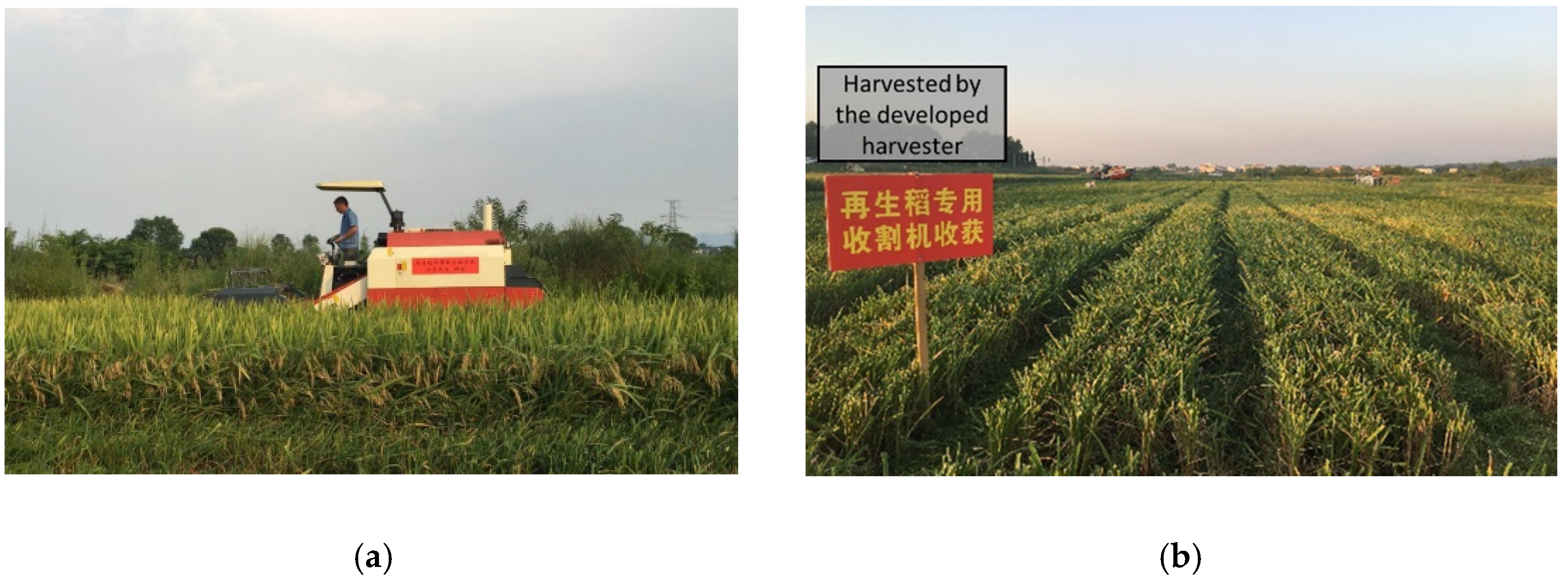
3.3. Field Test of the Developed Harvester

Figure 9a,b show the field test of the developed harvester and the stubble after harvesting, and Table 3 shows the performance indexes of the harvester. It was indicated that the harvester only caused 26.9% of stubble damage—this could greatly increase the yield of ratoon season compared to a conventional harvester. The panicle length and stubble height were 125 ± 80 mm and 332 ± 22 mm, respectively, which verified the availability of the methods developed for double-cutterbar configuration. The feeding quantity and working efficiency reached 5.0 kg·s−1 and 0.53 ha·h−1. The results indicated that the double-cutterbar structure developed based on rice plant deformation and shearing properties can successfully support the wide header in main crop rice harvesting. This would suggest that this structure can also be applied in regular rice harvesting and other stalk crops.

4. Conclusions

In this study, upper and lower cutterbar configuration methods were developed and verified through rice plant deformation experiments. Stalk shearing experiments were conducted to study the relationship between bevel angle and shearing properties. Field test of the developed harvester were carried out. The major conclusions can be drawn as follows:
(1)
The method developed based on rice plant deformation could offer considerable accuracy in upper configuration. The proposed method for a lower cutterbar could obtain a xlc, which is beneficial to cut stalks.
(2)
The shearing tests showed that shearing angle did not influence the shearing force (p < 0.05) of the whole range of rice stalk, while it significantly influenced the total shearing energy in Internode 2 and 3 (p < 0.05); the larger the shearing angle was, the more energy was consumed.
(3)
The stubble rolling rate, panicle length and stubble height of the tested harvester were 26.9%, 125 ± 80 mm and 332 ± 22 mm, respectively, indicating the functionality and practicability of the double-cutterbar structure developed.
In summary, the double-cutterbar structure developed based on rice plant deformation and shearing properties can successfully support a wide header in main crop rice harvesting.

Author Contributions

Conceptualization, M.H. and Y.L.; methodology, M.H.; software, M.H.; validation, A.C., Y.L. and L.X.; formal analysis, M.H.; investigation, M.H.; resources, M.H.; data curation, A.C.; writing—original draft preparation, M.H.; writing—review and editing, Y.L. and L.X.; visualization, Y.L.; supervision, Y.L.; project administration, Y.L.; funding acquisition, Y.L. All authors have read and agreed to the published version of the manuscript.

Funding

This research was funded by National Key Research of Development Program of China (grant number: 2016YFD0702004) and Jiangsu Agriculture Science and Technology Innovation Fund (JASTIF) (grant number: CX(19)3083).

Acknowledgments

We kindly like to thank Qiyuan Tang for providing test materials and field in Liuyang, Changsha, Hunan province of China.

Conflicts of Interest

The authors declare no conflict of interest.

References

  1. Mohan, R.; Balasubramaniam, N.; Aruna, L.; Narayanan, A. Economic Viability of Ratooning Rice. Madras Agric. J. 2015, 299–302. [Google Scholar]
  2. Hafeez, S.; Jin, T.; Zhou, Y. Factors Affecting Yield and Yield Components of Main and Ratoon Rice: A Review. Agric. Sci. Technol. 2017, 18, 1228–1231. [Google Scholar]
  3. Shin, J.-H.; Kim, S.; Park, S. Effects of Stubble Height, Irrigation and Nitrogen Fertilization on Rice Ratooning in Korea. Korean J. Crop Sci. 2015, 60, 431–435. [Google Scholar] [CrossRef]
  4. Dou, F.; Tarpley, L.; Chen, K.; Wright, A.L.; Mohammed, A.R. Planting Date and Variety Effects on Rice Main and Ratoon Crop Production in South Texas. Commun. Soil Sci. Plant Anal. 2016, 47, 2414–2420. [Google Scholar] [CrossRef]
  5. Lin, W.-x. Developmental Status and Problems of Rice Ratooning. J. Integr. Agric. 2019, 18, 246–247. [Google Scholar] [CrossRef]
  6. Yuan, S.; Cassman, K.G.; Huang, J.; Peng, S.; Grassini, P. Can Ratoon Cropping Improve Resource Use Efficiencies and Profitability of Rice in Central China. Field Crop. Res. 2019, 234, 66–72. [Google Scholar] [CrossRef] [PubMed]
  7. Yadi, R.; Ebrahimi, M.; Dastan, S. Ratooning Parameters of Two Rice Cultivar in Modified Planting Systems. Int. J. Trop. Med. 2016, 11. [Google Scholar]
  8. Zhang, G.; Zhang, Y.; Huang, J.; Zhai, K.; Zhou, Y.; Huang, H.; Fan, Q. Designing and performance testing a novel head spike harvester of ratoon rice. J. Huazhong Agric. Univ. 2016, 35, 131–136. [Google Scholar]
  9. Lu, K.; Zhang, G.; Peng, S.; Lei, Z.; Fu, J.; Zha, X.; Zhou, Y. Design and performance of tracked harvester for ratoon rice with double-headers and double threshing cylinders. J. Huazhong Agric. Univ. 2017, 36, 108–114. [Google Scholar]
  10. İnce, A.; Uğurluay, S.; Güzel, E.; Özcan, M.T. Bending and Shearing Characteristics of Sunflower Stalk Residue. Biosyst. Eng. 2005, 92, 175–181. [Google Scholar] [CrossRef]
  11. Esehaghbeygi, A.; Hoseinzadeh, B.; Khazaei, M.; Masoumi, A. Bending and Shearing Properties of Wheat Stem of Alvand Variety. World Appl. Sci. J. 2009, 6, 1028–1032. [Google Scholar]
  12. Chattopadhyay, P.S.; Pandey, K.P. Mechanical Properties of Sorghum Stalk in Relation to Quasi-Static Deformation. J. Agric. Eng. Res. 1999, 73, 199–206. [Google Scholar] [CrossRef]
  13. Inoue, F.; Kim, Y.; Hashiguchi, K.; Okayasu, T.; Kashima, J. Mechanical Characteristics of Rice Stalk. J. Jpn. Soc. Agric. Mach. 1998, 60, 97–102. [Google Scholar]
  14. Hirai, Y.; Inoue, E.; Mori, K.; Hashiguchi, K. Analysis of Reaction Forces and Posture of a Bunch of Crop Stalks During Reel Operations of a Combine Harvester. Agric. Eng. Int. CIGR J. 2002. [Google Scholar]
  15. Huang, M.; Li, Y.; Chen, A.; Xu, L. Numerical Calculation Method of Deflection Deformation of Rice Stalk. Appl. Sci. 2019, 9, 3125. [Google Scholar] [CrossRef] [Green Version]
  16. Alizadeh, M.R.; Habibi, F. A Comparative Study on the Quality of the Main and Ratoon Rice Crops. J. Food Qual. 2016, 39, 669–674. [Google Scholar] [CrossRef]
  17. Allameh, A.; Alizadeh, M.R. Specific Cutting Energy Variations under Different Rice Stem Cultivars and Blade Parameters. Idesia 2016, 34, 11–17. [Google Scholar] [CrossRef]
  18. Tabatabaei, K.R.; Borgheei, A. Measuring the Static and Dynamic Cutting Force of Stems for Iranian Rice Varieties. J. Agric. Sci. Technol. 2006, 8, 193–198. [Google Scholar]
  19. Miu, P. Combine Harvesters: Theory, Modeling, and Design; CRC Press: Boca Raton, FL, USA, 2015. [Google Scholar]
  20. Hirai, Y.; Inoue, E.; Mori, K. Application of a quasi-static stalk bending analysis to the dynamic response of rice and wheat stalks gathered by a combine harvester reel. Biosyst. Eng. 2004, 88, 281–294. [Google Scholar] [CrossRef]
Figure 1. Diagram of a double-cutterbar structure. (1) Lower cutterbar, (2) upper cutterbar, (3) auger, (4) header frame, (5) reel.
Applsci 10 04432 g001
Figure 2. Rice plant (a) deformation and (b) force analysis before cut by the upper cutterbar. xuc, yuc are the horizontal and vertical coordinates of the upper cutterbar blade midpoint in mm, respectively; F is the reel acting force exerted on stalk, and Fh, Fτ are its component forces on horizontal and tangential direction, N; G is the gravity of the panicle, and Gh, Gτ are its component forces on horizontal and tangential direction, N; MG is the additional torque when the G is moved to point A2, N·mm; hB1 and hB2 are the heights of the panicle lowest point before and after deformation, mm; ΔC is the plant deflection at the height of the upper cutterbar, mm; p is the distance between crop and auger center, mm; ltine is the length of the reel tine, mm.
Applsci 10 04432 g002
Figure 3. Rice plant partition and calculation. Fre is the resultant force of Fh, Wh and FM, N; hA1 and hA2 are the heights of point A before and after deformation, mm; δA and ΔA are the vertical and horizontal displacement of point A2, mm; θ8 is the angle between the tangent line of point A2 and the axis Y, (°); θi represents the angle between the tangent line of point Ki and the axis Y, (°).
Applsci 10 04432 g003
Figure 4. Stalk deformation before cut by lower cutterbar. hD is the height of the header frame lowest point, mm; xlc, ylc are the horizontal and vertical coordinates of the lower cutterbar blade midpoint, mm, respectively.
Applsci 10 04432 g004
Figure 5. (a) Rice stalk division and numbering; (b) shearing test rig. (1) Placement platform, (2) stalk, (3) blade, (4) blade holder, (5) texture analyzer
Applsci 10 04432 g005
Figure 6. (a) Assembly and (b) field test of the double-cutterbar prototype.
Applsci 10 04432 g006
Figure 7. The contrast of fitted and measured rice plant.
Applsci 10 04432 g007
Figure 8. Shearing properties variation on whole stalk.
Applsci 10 04432 g008
Figure 9. (a) Field test of the developed harvesting and (b) the stubble after harvesting.
Applsci 10 04432 g009
Table 1. The basic parameters of the developed harvester.
ItemValue
Header width/mm2600
Caterpillar width/mm350
Machine power/kW51.5
Reel speed/rpm45
Auger speed/rpm200
Table 2. Shearing properties on different cutting positions and angles.
12345678
Maximum shearing force/N8.5 ± 5.9a14.2 ± 2.8a14.0 ± 3.0a16.0 ± 4.3a19.0 ± 3.5a17.3 ± 3.5a15.6 ± 3.1a14.3 ± 2.4a
15°8.0 ± 2.1a12.8 ± 1.5a12.9 ± 2.1a15.4 ± 4.2a17.5 ± 2.6a18.0 ± 12.8a15.8 ± 1.1a16.5 ± 1.3a
30°8.6 ± 3.0a12.9 ± 2.9a12.5 ± 1.6a14.7 ± 3.2a17.6 ± 5.4a17.0 ± 3.0a16.7 ± 2.8a16.1 ± 3.6a
9101112131415
16.6 ± 2.7a20.7 ± 1.7a23.0 ± 3.1a24.0 ± 4.3a25.0 ± 11.0a24.8 ± 3.3a27.0 ± 6.8a
15°18.4 ± 2.2a21.3 ± 4.5a22.0 ± 6.2a21.8 ± 3.0a22.0 ± 6.0a24.8 ± 10.7a28.0 ± 8.2a
30°17.6 ± 3.3a21.4 ± 3.0a23.4 ± 2.4a26.0 ± 3.0a26.5 ± 12.2a27.0 ± 5.1a29.5 ± 6.2a
12345678
Total shearing energy/mJ12.6 ± 2.8a29.7 ± 8.3a25.0 ± 8.3a35.0 ± 19.1a40.0 ± 25.2a42.0 ± 22.6a46.9 ± 10.7a49.4 ± 10.3a
15°18.3 ± 3.2a31.1 ± 7.6a28.1 ± 7.2a36.6 ± 13.2a44.5 ± 4.4a62.0 ± 54.7b62.0 ± 16.2b65.5 ± 15.8b
30°19.1 ± 2.4a29.3 ± 7.7a30.2 ± 6.8a39.1 ± 12.3a48.4 ± 19.4a70.0 ± 15.6b72.7 ± 16.8b74.9 ± 16.7c
9101112131415
54.5 ± 9.5a58.8 ± 3.7a62.2 ± 13.0a62.5 ± 19.6a70.0 ± 44.8a70.5 ± 55.4a85.0 ± 19.3a
15°70.0 ± 27.9b70.3 ± 18.1b71.2 ± 42.4b75.0 ± 29.7b80.0 ± 8.2b99.8 ± 68.8b101.0 ± 45.2b
30°78.0 ± 21.1c80.0 ± 8.4c85.0 ± 23.3c90.0 ± 19.2c109.9 ± 44.1c113.8 ± 45.7c130.0 ± 57.3c
Values presented are mean ± standard deviation from the original data; the replication number of each cutting point is 10; dissimilar lower case group labels (a, b, c) represent a significant difference (p < 0.05) among different cutting angles on the same cutting position.
Table 3. The results of the comparative test.
ItemDeveloped Harvester
Stubble rolling rate/%26.9
Panicle straw length/mm125 ± 80
Stubble height/mm332 ± 22
Feeding rate/kg·s−14.9
Working efficiency/ha·h−10.53

