Article

Compressive Sensing Imaging Based on Modulation of Atmospheric Scattering Medium

1
Key Laboratory of Electronics and Information Technology for Space System, National Space Science Center, Chinese Academy of Sciences, Beijing 100190, China
2
University of Chinese Academy of Sciences, Beijing 100049, China
*
Author to whom correspondence should be addressed.
Appl. Sci. 2020, 10(13), 4466; https://doi.org/10.3390/app10134466
Submission received: 2 June 2020 / Revised: 19 June 2020 / Accepted: 23 June 2020 / Published: 28 June 2020
(This article belongs to the Section Optics and Lasers)

Abstract

:
Long-distance imaging in time-varying scattering media, such as atmosphere, is a significant challenge. Light is often heavily diffused while propagating through scattering media, because of which the clear imaging of objects concealed by media becomes difficult. In this study, instead of suppressing diffusion by multiple scattering, we used natural randomness of wave propagation through atmospheric scattering media as an optimal and instantaneous compressive imaging mechanism. A mathematical model of compressive imaging based on the modulation of atmospheric scattering media was established. By using the Monte Carlo method, the atmospheric modulation matrix was obtained, and the numerical simulation of modulation imaging of atmospheric scattering media was performed. Comparative experiments show that the atmospheric matrix can achieve the same modulation effect as the Hadamard and Gaussian random matrices. The effectiveness of the proposed optical imaging approach was demonstrated experimentally by loading the atmospheric measurement matrix onto a digital micromirror device to perform single pixel compressive sensing measurements. Our work provides a new direction to ongoing research in the field of imaging through scattering media.

1. Introduction

Imaging through scattering media has important applications in various fields, such as optical remote sensing and automatic driving. Intuitively, the presence of scattering media is a disadvantage for optical imaging. Therefore, many scientists are working to develop ways to preserve the photons that are not diffused by the scattering medium, otherwise known as “ballistic photons” [1,2]. Other researchers have developed anti-scattering media imaging processes based on second-order intensity correlation [3], compressive sensing (CS) [4,5], and the phase-shift method [6,7]. However, these methods of using ballistic photons are limited because the intensity of the non-scattered light decreases exponentially with distance, which makes these methods difficult or infeasible at transmission distances longer than the mean free path of the medium.
From another perspective, scattering media can play a beneficial role in imaging. The “memory effect” [8,9,10] of the scattering media can “remember” significant information about the incident wave front. Based on this effect, the wave front shaping technique [11,12,13,14] can be used for focusing and imaging through scattering media. This method requires assisted devices, which makes it impractical for many applications. Another method based on the “memory effect” is speckle correlation imaging [15,16,17,18]. However, current implementations are restricted to thin scattering media, since the “memory-effect” range is inversely proportional to the medium thickness. In 2010, Popoff et al. [19,20,21] applied a spatial light modulator together with a full-field interference method to experimentally measure the monochromatic transmission matrix (TM) of a complex medium. They demonstrated that a multiple scattering medium can be considered as a compressive imaging device [22,23]. The limitation of this method is that it assumes that the scattering medium does not change. However, in most cases, the scattering medium is variable.
Most research on imaging through scattering media is limited to the microscopic and mesoscopic properties of a complex medium. The effectiveness of the existing methods has not been proved for long-distance transmission and time-varying complex scatter media, such as the atmosphere. This application is essential for any optical remote sensing imaging process. In this study, we demonstrate that atmospheric scattering media can be used as a digital micromirror device (DMD) for CS imaging, and the image can be reconstructed through the iteration of the algorithm.
The remainder of this paper is organized as follows. In Section 2, we describe the CS theory and the CS imaging model based on the modulation of atmospheric scattering medium. The numerical simulation of CS imaging performed by us, using the atmospheric measurement matrix, is discussed in Section 3, while Section 4 presents the CS imaging experiment carried out. Section 5 concludes the paper and summarizes our key results. It also presents the limitations and future scope of the study.

2. Theoretical Basis and Imaging Model

Shannon–Nyquist sampling theorem proposes that in order to ensure the sampled signal can restore the complete information of the original signal, the sampling frequency is at least twice the bandwidth of the original signal. In 2004, Candès et al. [4,24] proposed a new guiding theory of information acquisition called CS. According to this theory, if a high-dimensional signal can be sparsely represented in a projection domain, it can be mapped onto a low-dimensional space. By solving the nonlinear optimization problem, the original signal can be accurately recovered in a way far below the Shannon–Nyquist sampling rate. Its mathematical expression [25] is:
y = Φ x = Φ   ( Ψ   s ) = ( Φ   Ψ ) s = Θ   s
where y is the measured value of the M-dimensional column vector, Φ is the M × N ( M N ) measurement matrix, x is the original signal of the N-dimensional column vector, and Ψ is a sparse N × N basis matrix. The product of Φ and Ψ gives an M × N matrix, Θ. s is the projection value of x on the sparse basis Ψ, meaning it has only a small group of coefficients that are nonzero. Since the dimensional relationship of the matrix is M < N , the solution of the signal is ill-conditioned (non-deterministic polynomial hard) [26,27]. It must be resolved by using a proper reconstruction algorithm. Various solutions have been developed, such as orthogonal matching pursuit (OMP) [28], basic pursuit (BP), and expectation-maximization [29].
For the CS imaging model, the measurement matrix is generated by the DMD. Popoff et al. have shown that the TM of the optical multiple scattering materials is an excellent candidate for CS [22]. In this study, we will demonstrate through theory, simulation, and experiments that the imaging can be produced using the atmospheric scattering medium as a DMD for CS.
CS imaging based on modulation of atmospheric scattering medium is shown in Figure 1. The collimated laser beam passes through the atmosphere, over a long distance, to the target. The light field is transmitted through the target and collected by the bucket detector. Based on the analysis above, the measurement matrix, Φ, of the mathematical expression in Equation (1) is determined by the atmospheric scattering medium. When the laser is transmitted through the atmosphere, it is modulated by the medium. Owing to the stochastic and time-varying characteristics of the scattering medium, the modulation process also changes randomly over time. A series of different modulation patterns are obtained to illuminate the target. The modulation effect becomes more pronounced as the transmission distance increases. Long distances, which are difficult to overcome in scattering imaging, become favorable conditions in transmission imaging. Meanwhile, to further ensure the randomness of the modulation process, we designed the laser in such a way that it enters the atmospheric medium at random angles (expressed as the zenith angle θ0 and azimuth angle φ0 in Figure 1). The total light intensity passing through the target is collected by the barrel detector. The target image is reconstructed using measured intensity values with the proper computer algorithm.

3. Numerical Simulation

When a laser beam propagates in the atmosphere, the modulation effect of the atmosphere can be described by the atmospheric point spread function (PSF). Monte Carlo (MC) is a common method used to simulate the atmospheric PSF [30,31,32,33]. For MC simulation, the atmosphere environment of light propagation is constructed with the moderate spectral resolution atmospheric transmittance (MODTRAN) algorithm and computer model, which divides the atmosphere, from 0 to 100 km high, into 34 layers. Physical parameters for each layer, including air pressure, temperature, absorption, and scatter coefficients are defined. The MODTRAN model is used to calculate the optical thickness of molecules and aerosols at different heights and the MC method is used to simulate photon propagation in the atmosphere. For CS imaging based on modulation of atmospheric scattering medium, a laser beam passes through the atmosphere and illuminates the target. The direction of laser emission relative to the target is represented by the zenith angle θ0 and azimuth angle φ0. During the laser propagation, photons randomly collide with molecules or aerosols in the atmosphere. The molecule collision probability may be expressed as τm/[τm + τa] where τm and τa are the molecule and aerosol optical thickness, respectively. A random number r0 ( 0 r 0 1 ) is defined to describe the collision property. If 0 ≤ r0τm/[τm + τa], photons will collide with molecules. If τm/[τm + τa] < r0 ≤ 1, photons will collide with aerosols. After any collision, the direction of photon propagation will be decided by the scattering phase function. For molecule and aerosol collisions, the phase functions used are the Rayleigh [34] and Henyey–Greenstein [35] phase functions, respectively. The Rayleigh phase function is defined as:
P ( θ ) = 3 16 π ( 1 + c o s 2 θ )
where θ is the scattering angle. The Henyey–Greenstein phase function is defined as:
P ( θ ) = 1 4 π 3 2 ( 1 g 2 ) ( 1 + c o s 2 θ ) ( 2 + g 2 ) ( 1 + g 2 2 g c o s θ ) 3 / 2
where g is the asymmetry factor. The normalized phase function is defined as:
p ( θ ) = 0 θ P ( θ ) d θ 0 2 π P ( θ ) d θ
where the random numbers r1 and r2 ( 0 r 1 , 2 1 ) are used to decide the direction after collision, based on the following equations:
r 1 = p ( θ )
φ = 2 π r 2
After the direction of the new trajectory is determined, the photon will propagate along a free path l represented by the random number r3 ( 0 r 3 1 ) in the direction (θ, φ) until it collides with another atmosphere particle [35]:
l = l n ( 1 r 3 )
where l is the optical distance between the two collisions. The collision and propagation processes are repeated until the photon strikes the target surface or is extinguished in the atmosphere. The positions of all photons on the target surface are recorded to obtain the atmospheric PSF.
Examples of the atmospheric PSF are shown in Figure 2. The laser wavelength was 532 nm. The 1976 U.S. Standard Atmosphere model was used for the atmosphere and the rural extinction model was used for the aerosols. Since the scattering characteristics of the atmosphere were used for CS imaging, this requires that the atmosphere be turbid. Generally, the degree of turbidity of the atmosphere can be expressed by the surface meteorological range (also called standard visibility). The lower the surface meteorological range, the more turbid the atmosphere. In the simulation, we set the surface meteorological range to vary randomly over time from 0.5 km to 2 km. The laser passed through the entire atmosphere and the transmission distance was set to 100 km. The emitting directions were random with two propagation paths of zenith and azimuth angles of 160° and 355°, respectively, and 176° and 54°, respectively. The pixel number of the simulation was 32 × 32 and the side length of every pixel was 30 m. The PSF obtained was a single modulation Φi in CS. By changing the emitting direction randomly, 1024 modulation patterns were simulated, which were used to generate the measurement matrix meeting the requirements of full sampling.
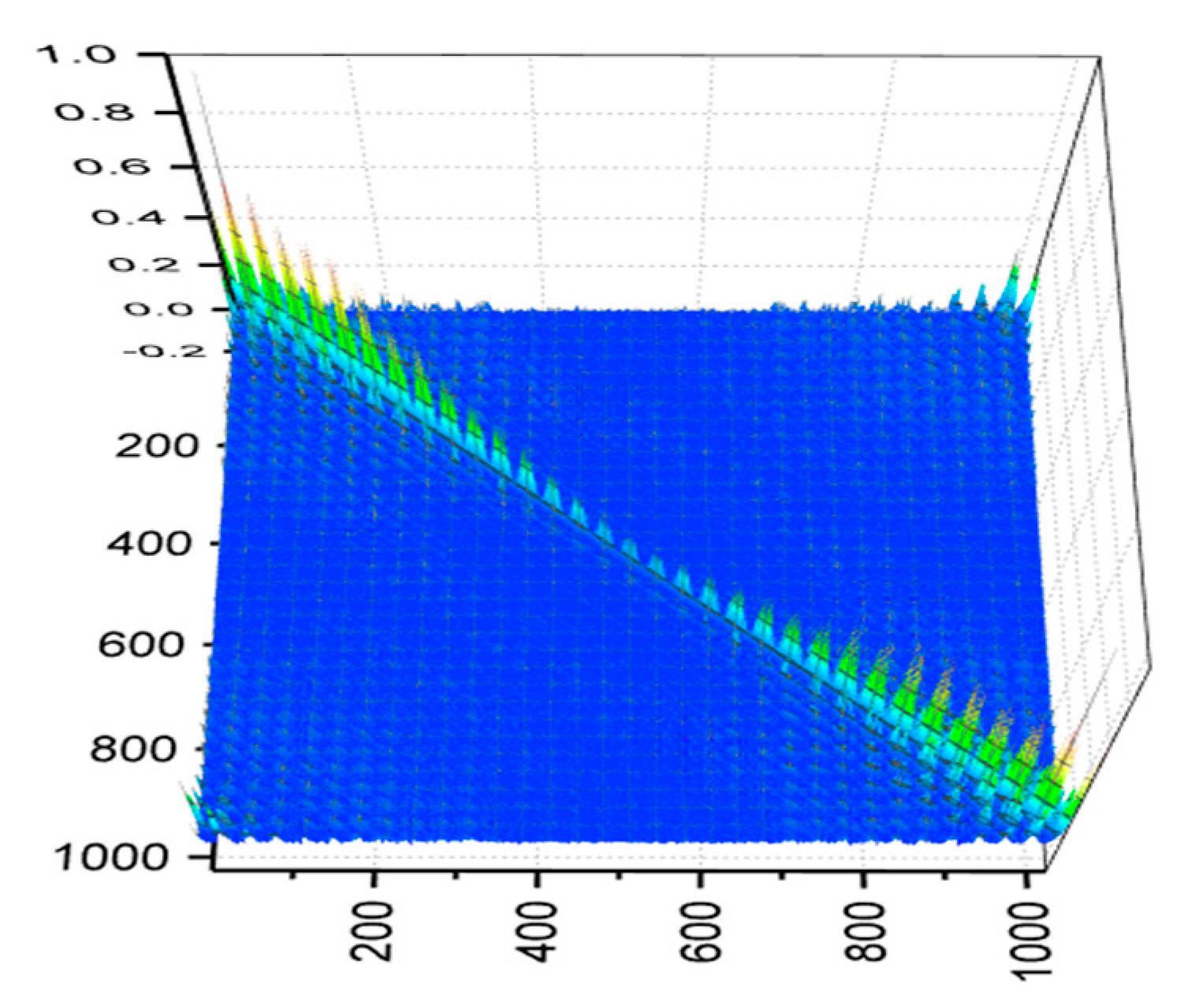
The measurement matrix is crucial for the CS method. General modulation measurement matrices (such as the Hadamard matrix and the Gaussian random matrix) are designed in advance. In this case, the atmospheric modulation measurement matrix was essentially determined by the real-time changes in the atmosphere. Moreover, the modulation mode of the atmosphere was grayscale (as shown in Figure 2), while the general modulation is binary. This is an innovative application of CS methods. To ensure that the original signal can be reconstructed from the observations, the measurement matrix needs to meet certain requirements. The restricted isometry property (RIP) [36,37] is the first important condition to consider. However, it is difficult to judge whether a matrix satisfies the RIP or not, and it is not practical to use the RIP to guide the design of the measurement matrix. Donoho et al. proposed that if the correlation coefficients between the selected sparse basis (Ψ) and measurement matrix (Φ) are small, then the RIP condition will be satisfied with a high probability. It is inferred that if the diagonal elements of the Gram matrix G [38] ( G = Θ ˜ T Θ ˜ , where Θ ˜ is the column-normalized version of Θ , and (   ) T denotes the transposition) are close to 1, with a high probability, and the amplitudes of the non-diagonal elements are small, the matrix meets the RIP condition [39]. To verify the RIP condition, the common Fourier base is used as the sparse basis Ψ. Figure 3 shows the element distribution diagram of the Gram matrix G. The Figure 3 shows that the atmospheric measurement matrix satisfies the RIP condition.
We performed the CS simulation experiment using the measurement matrix obtained by the backward MC simulation. The simulation process consists of two parts: the measurement simulation and the reconstruction simulation. In the measurement process, the atmospheric medium was constructed by the MODTRAN model. The position of the laser was changed randomly and a series of single modulation patterns, Φi, were generated for different laser propagation directions, which were combined to form the measurement matrix, Φ. The measurement matrix was multiplied by the original signal, x, to simulate the detection value, y, of the bucket detector. In the reconstruction simulation process, based on the simulated detection values and the selected Fourier sparse basis Ψ, the basic OMP algorithm recovered the original image.
Examples of the reconstruction are shown in Figure 4. The peak signal-to-noise ratio (PSNR) and structural similarity image measurement (SSIM) are two objective criteria for evaluating image quality defined as:
P S N R = 10   l o g 10 ( 1 i = 1 N ( x i x ^ i ) 2 / N )
S S I M ( x i , x ^ i ) = ( 2 μ x i μ x ^ i + C 1 ) ( 2 δ x i x ^ i + C 2 ) ( μ x i 2 + μ x ^ i 2 + C 1 ) ( δ x i 2 + δ x ^ i 2 + C 2 )
where x i represents the original image, x ^ i represents the reconstructed image, and N is the total number of pixels. μ x i and μ x ^ i represent the mean values of the images x i and x ^ i , δ x i and δ x ^ i represent the variances of the images x i and x ^ i , and δ x i x ^ i represents the covariance of the images x i and x ^ i . C1 and C2 are taken as constants to prevent the denominator from being equal to zero.
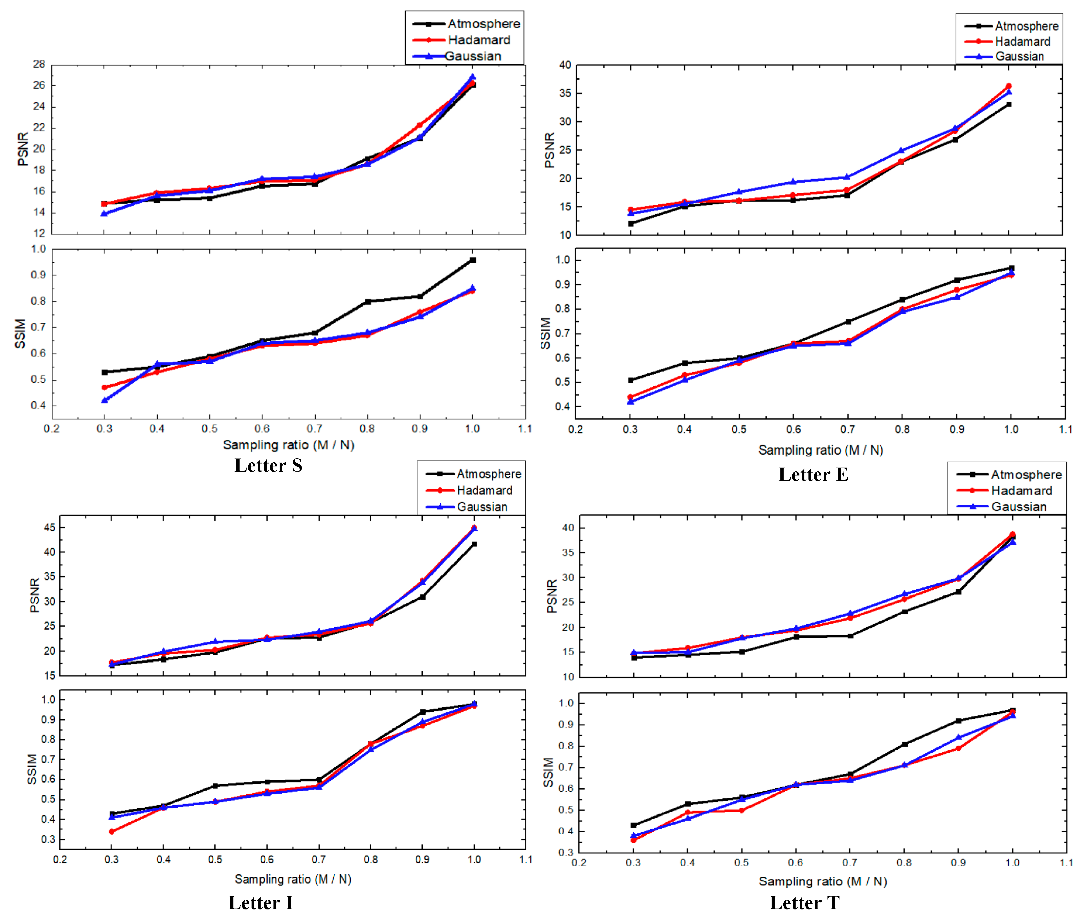
The simulation results proved that the atmosphere could replace the DMD in the CS experiment, so as to achieve the purpose of imaging through atmospheric scattering media. As the sampling ratio increases, the quality of imaging becomes better. For comparison of the simulation results, we also used the Hadamard and Gaussian random matrices as the measurement matrices to reconstruct the image. The comparison of the image quality obtained using the OMP algorithm is shown in Figure 5.
Figure 5 shows this comparison of the reconstructed image quality between the simulated atmospheric matrix, the Hadamard matrix, and the random Gaussian matrix modulation. It further illustrates the feasibility of replacing the DMD with the atmosphere to achieve imaging through atmospheric scattering media.

4. Experiment Results

For further validation, the CS imaging experiment was carried out. The schematic diagram of the experimental setup is shown in Figure 6. The light source was a laser with a wavelength of 532 nm (ADR-1805, Changchun Laser Photonics Technology Co., Ltd., Changchun, China). A collimator (GCO-25, Daheng New Era Technology Co., Ltd., Beijing, China) enlarged the laser beam by a factor of 10 and projected it onto a DMD (DLP F6500, Jinfei Photoelectric Technology Co., Ltd., Henan, China). The DMD had more than 2 million micromirrors with a resolution of up to 1920 × 1080. The atmospheric modulation patterns with 32 × 32 units were generated by MC simulation and loaded onto the DMD, so the unit of the atmospheric modulation patterns displayed onto the DMD were composed of 32 × 32 micromirrors. The modulated light illuminated the target and was then reflected. An optical collecting system formed by a lens group focused the light within the sensitive area of a photomultiplier tube (PMT) (H10722-20, Hamamatsu Photonics Co., Ltd., Hamamatsu City, Japan). The detected signal from the PMT was digitized by an analog-to-digital converter (DAQ-2213, Adlink Technology Co., Ltd., New Taipei City, Taiwan). A program written in C++ was customized to control the measurement process.
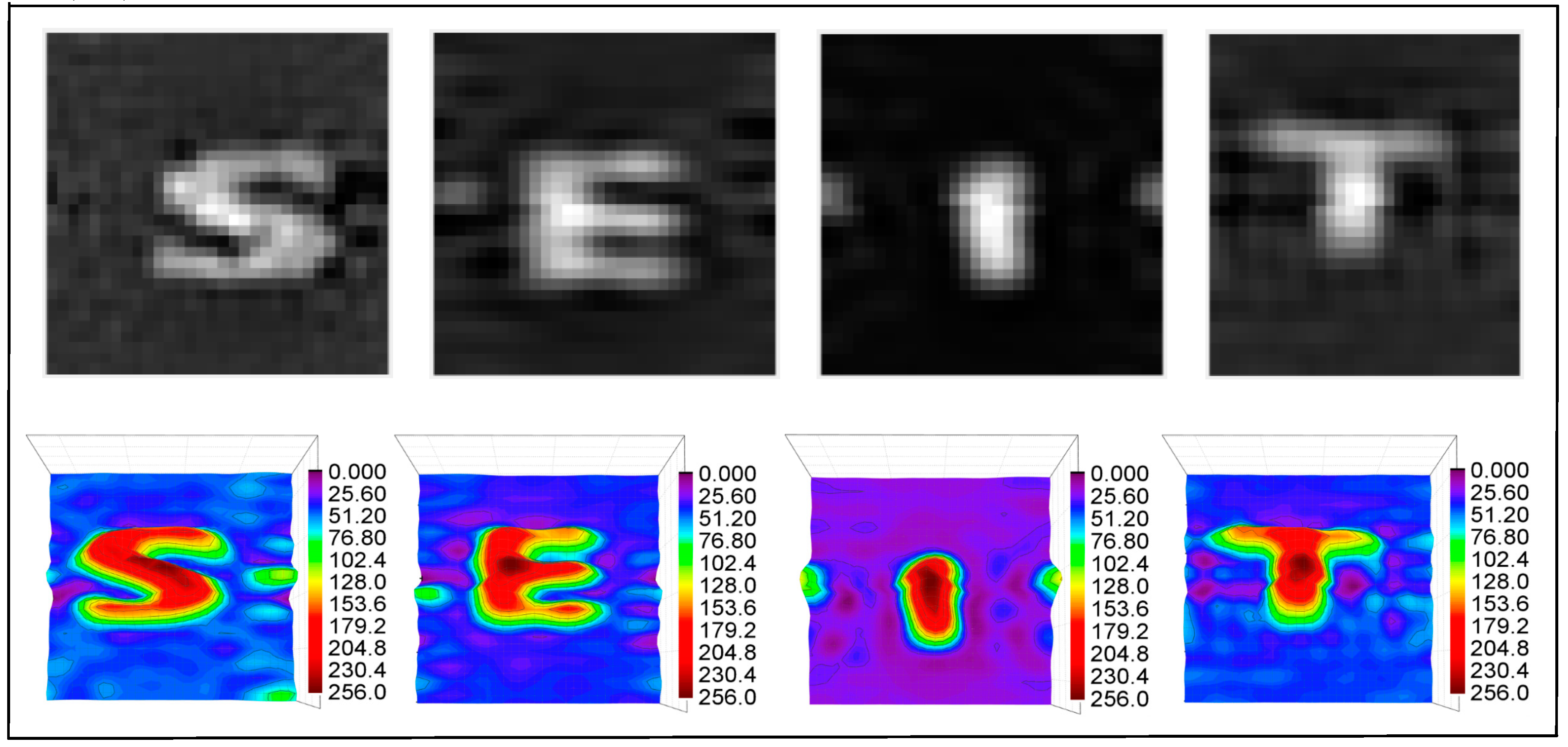
Using the measured values obtained by the PMT, the OMP algorithm reconstructed the image. The experimental results are shown in Figure 7. The top row shows the reconstructed images and the bottom row shows the 3D displays of the images. The quality of the experimental results was not quite as good as the simulation results. One possible reason is that, after beam expansion, the laser light source was not uniformly collimated light, but a Gauss-like light source with a strong middle and a weak surrounding. Thus, the intensity of the reconstructed image around the middle intersection is relatively high. Nevertheless, the characteristics of the target can be seen clearly. The experimental results also proved that the atmospheric scattering media can be used as a DMD for CS imaging.

5. Conclusions

In this paper, we have confirmed that the multiple scattering medium of the atmosphere can be used for CS long-distance imaging. The stochastic and time-varying characteristics of the scattering medium were helpful in obtaining a series of modulation patterns, which form the measurement matrix. At the same time, the random laser transmission direction was designed to ensure the randomness of the modulation process. By using the MC method, atmospheric modulation patterns were simulated and the measurement matrix was obtained. First, it was proved that the generated matrix satisfies the RIP condition. Then, the numerical simulation of CS imaging was performed using the atmospheric measurement matrix, and reconstructed images were obtained. Finally, the atmospheric measurement matrix was loaded onto the DMD for optical experiments to verify the proposed method.
For realistic applications, our method still faces a huge challenge, as the atmospheric modulation patterns should be well-characterized. In our current research, the atmospheric modulation of light is simulated by the MC method, which differs from the real scenario. As mentioned in Reference [40], the simulation results are not guaranteed to be fully reproducible and scattering phase function should be considered carefully for the high degree of asymmetry in the turbid atmosphere. By now, the asymmetry factor in the aerosol scattering phase function is used to improve the accuracy of the simulation results. Yet detailed quantitative assessment is not available. Moreover, the information of the laser transmission direction and the optical thickness profiles of molecules and aerosols are required to compute or simulate the atmosphere modulation pattern. This will be investigated in our future work.

Author Contributions

Conceptualization, Z.Y. and X.P.; methodology, X.M. and X.L.; software, Y.L., X.L. and W.N.; validation, X.L. and X.M.; formal analysis, X.L. and X.M.; investigation, X.L. and X.M.; data curation, X.L. and X.M.; writing—original draft preparation, X.L. and X.M.; writing—review and editing, X.M.; supervision, Z.Y. and X.P. All authors have read and agreed to the published version of the manuscript.

Funding

This research was funded by the key Cultivation Foundation of the National Space Science Center, Chinese Academy of Sciences.

Conflicts of Interest

The authors declare no conflict of interest.

References

  1. Wang, L.; Ho, P.P.; Liu, C.; Zhang, G.; Alfano, R.R. Ballistic 2-D Imaging through Scattering Walls Using an Ultrafast Optical Kerr Gate. Science 1991, 253, 769–771. [Google Scholar] [CrossRef]
  2. Shiratori, A.; Obara, M. Photorefractive coherence-gated interferometry. Rev. Sci. Instrum. 1998, 69, 3741–3745. [Google Scholar] [CrossRef]
  3. Gong, W.L.; Han, S.H. Correlated imaging in scattering media. Opt. Lett. 2011, 36, 394–396. [Google Scholar] [CrossRef] [PubMed] [Green Version]
  4. Donoho, D.L. Compressed sensing. IEEE Trans. Inf. Theor. 2006, 52, 1289–1306. [Google Scholar] [CrossRef]
  5. Durán, V.; Soldevila, F.; Irles, E.; Clemente, P.; Tajahuerce, E.; Andrés, P.; Lancis, J. Compressive imaging in scattering media. Opt. Express 2015, 23, 14424–14433. [Google Scholar] [CrossRef] [PubMed]
  6. Chen, H.C.; Shi, J.H.; Liu, X.L.; Niu, Z.Z.; Zeng, G.H. Single-pixel non-imaging object recognition by means of Fourier spectrum acquisition. Opt. Commun. 2018, 413, 269–275. [Google Scholar] [CrossRef]
  7. Deng, H.X.; Gao, X.C.; Ma, M.C.; Yao, P.C.; Guan, Q.T.; Zhong, X.; Zhang, J. Fourier single-pixel imaging using fewer illumination patterns. Appl. Phys. Lett. 2019, 114, 5. [Google Scholar] [CrossRef]
  8. Freund, I.; Kaveh, M.; Rosenbluh, M. Dynamic Multiple-Scattering—Ballistic photons and the breakdown of the photon-diffusion approximation. Phys. Rev. Lett. 1988, 60, 1130–1133. [Google Scholar] [CrossRef]
  9. Freund, I.; Rosenbluh, M.; Berkovits, R.; Kaveh, M. Coherent backscattering of light in a quasi-2-dimensional system. Phys. Rev. Lett. 1988, 61, 1214–1217. [Google Scholar] [CrossRef]
  10. Freund, I.; Rosenbluh, M.; Feng, S. Memory effects in propagation of optical waves through disordered media. Phys. Rev. Lett. 1988, 61, 2328–2331. [Google Scholar] [CrossRef]
  11. Reijn, S.M.; Pinheiro, F.A.; Geskus, D.; Wetter, N.U. Enabling focusing around the corner in multiple scattering media. Appl. Opt. 2015, 54, 7740–7746. [Google Scholar] [CrossRef] [PubMed]
  12. Katz, O.; Small, E.; Silberberg, Y. Looking around corners and through thin turbid layers in real time with scattered incoherent light. Nat. Photonics 2012, 6, 549–553. [Google Scholar] [CrossRef]
  13. Frostig, H.; Small, E.; Daniel, A.; Oulevey, P.; Derevyanko, S.; Silberberg, Y. Focusing light by wavefront shaping through disorder and nonlinearity. Optica 2017, 4, 1073–1079. [Google Scholar] [CrossRef]
  14. Yu, H.; Lee, K.; Park, Y. Ultrahigh enhancement of light focusing through disordered media controlled by mega-pixel modes. Opt. Express 2017, 25, 8036–8047. [Google Scholar] [CrossRef] [PubMed] [Green Version]
  15. Li, H.J.; Wu, T.F.; Liu, J.T.; Gong, C.M.; Shao, X.P. Simulation and experimental verification for imaging of gray-scale objects through scattering layers. Appl. Opt. 2016, 55, 9731–9737. [Google Scholar] [CrossRef] [PubMed]
  16. Wang, Z.P.; Jin, X.; Dai, Q.H. Non-invasive imaging through strongly scattering media based on speckle pattern estimation and deconvolution. Sci. Rep. 2018, 8, 11. [Google Scholar]
  17. Liao, M.H.; Lu, D.J.; He, W.Q.; Pedrini, G.; Osten, W.; Peng, X. Improving reconstruction of speckle correlation imaging by using a modified phase retrieval algorithm with the number of nonzero-pixels constraint. Appl. Opt. 2019, 58, 473–478. [Google Scholar] [CrossRef]
  18. Stern, G.; Katz, O. Noninvasive focusing through scattering layers using speckle correlations. Opt. Lett. 2019, 44, 143–146. [Google Scholar] [CrossRef] [Green Version]
  19. Popoff, S.M.; Lerosey, G.; Carminati, R.; Fink, M.; Boccara, A.C.; Gigan, S. Measuring the Transmission Matrix in Optics: An approach to the study and control of light propagation in disordered media. Phys. Rev. Lett. 2010, 104, 100601. [Google Scholar] [CrossRef]
  20. Popoff, S.; Lerosey, G.; Fink, M.; Boccara, A.C.; Gigan, S. Image transmission through an opaque material. Nat. Commun. 2010, 1, 81. [Google Scholar] [CrossRef]
  21. Popoff, S.M.; Lerosey, G.; Fink, M.; Boccara, A.C.; Gigan, S. Controlling light through optical disordered media: Transmission matrix approach. New J. Phys. 2011, 13, 123021. [Google Scholar] [CrossRef]
  22. Liutkus, A.; Martina, D.; Popoff, S.; Chardon, G.; Katz, O.; Lerosey, G.; Gigan, S.; Daudet, L.; Carron, I. Imaging with nature: Compressive imaging using a multiply scattering medium. Sci. Rep. 2014, 4, 5552. [Google Scholar] [CrossRef] [PubMed] [Green Version]
  23. Zhuang, B.; Xu, C.; Geng, Y.; Zhao, G.; Chen, H.; He, Z.; Wu, Z.; Ren, L. Round-trip imaging through scattering media based on optical transmission matrix. Chin. Opt. Lett. 2018, 16, 041102. [Google Scholar] [CrossRef]
  24. Candes, E.J.; Romberg, J.; Tao, T. Robust uncertainty principles: Exact signal reconstruction from highly incomplete frequency information. IEEE Trans. Inf. Theory 2006, 52, 489–509. [Google Scholar] [CrossRef] [Green Version]
  25. Candes, E.J.; Wakin, M.B. An introduction to compressive sampling. IEEE Signal Process. Mag. 2008, 25, 21–30. [Google Scholar] [CrossRef]
  26. Mallat, S.G.; Zhang, Z.F. Matching pursuits with time-frequency dictionaries. IEEE Trans. Signal Process. 1993, 41, 3397–3415. [Google Scholar] [CrossRef] [Green Version]
  27. Recht, B.; Fazel, M.; Parrilo, P.A. Guaranteed minimum-rank solutions of linear matrix equations via nuclear norm minimization. SIAM Rev. 2010, 52, 471–501. [Google Scholar] [CrossRef] [Green Version]
  28. Tropp, J.A.; Gilbert, A.C. Signal Recovery from random measurements via orthogonal matching pursuit. IEEE Trans. Inf. Theory 2007, 53, 4655–4666. [Google Scholar] [CrossRef] [Green Version]
  29. Zayyani, H.; Babaie-Zadeh, M.; Jutten, C. Decoding real-field codes by an iterative expectation-maximization (em) algorithm. In Proceedings of the 2008 IEEE International Conference on Acoustics, Speech and Signal Processing, Las Vegas, NV, USA, 31 March–4 April 2008. [Google Scholar]
  30. Hongshun, L.; Wei, L. Analysis of the adjacency effect in satellite remote sensing by using backward Monte Carlo method. J. Huazhong Univ. Sci. Technol. 2004, 3201, 1–3. [Google Scholar]
  31. Modest, M.F. Backward Monte Carlo simulations in radiative heat transfer. J. Heat Trans. T. ASME 2003, 125, 57–62. [Google Scholar] [CrossRef]
  32. Reinersman, P.N.; Carder, K.L. Monte-Carlo simulation of the atmospheric point-spread function with an application to correction for the adjacency effect. Appl. Opt. 1995, 34, 4453–4471. [Google Scholar] [CrossRef] [PubMed]
  33. Ma, X.S.; Wang, H.D.; Li, L.G.; Yang, Z.; Meng, X. Neural network simulation of the atmospheric point spread function for the adjacency effect research. In Proceedings of the SPIE Remote Sensing, Edinburgh, UK, 26–29 September 2016. [Google Scholar]
  34. Gordon, H.R.; Brown, J.W.; Evans, R.H. Exact Rayleigh Scattering calculations for use with the Nimbus-7 coastal zone color scanner. Appl. Opt. 1988, 27, 862–871. [Google Scholar] [CrossRef] [PubMed]
  35. Ma, X.S.; Guo, X.Y.; Meng, X.; Yang, Z.; Peng, X.D.; Li, L.G.; Xie, W.M. Simulation and analysis of the adjacency effect in earth-imaging process of the optical remote sensing. J. Infrared Millim. Waves 2015, 34, 250–256. [Google Scholar]
  36. Candes, E.J.; Tao, T. Decoding by linear programming. IEEE Trans. Inf. Theory 2005, 51, 4203–4215. [Google Scholar] [CrossRef] [Green Version]
  37. Candès, E.J. The restricted isometry property and its implications for compressed sensing. Comptes Rendus Math. 2008, 346, 589–592. [Google Scholar] [CrossRef]
  38. Donoho, D.L.; Elad, M. Optimally sparse representation in general (nonorthogonal) dictionaries via l(1) minimization. Proc. Natl. Acad. Sci. USA 2003, 100, 2197–2202. [Google Scholar] [CrossRef] [Green Version]
  39. Abolghasemi, V.; Ferdowsi, S.; Makkiabadi, B.; Sanei, S. On optimization of the measurement matrix for compressive sensing. In Proceedings of the 2010 18th European Signal Processing Conference, Aalborg, Denmark, 23–27 August 2010; Kleijn, B., Larsen, J., Eds.; European Assoc Signal Speech & Image Processing-Eurasip: Kessariani, Greece, 2010; pp. 427–431. [Google Scholar]
  40. Kocifaj, M. Ground albedo impacts on higher-order scattering spectral radiances of night sky. J. Quant. Spectrosc. Radiat. Transf. 2019, 239, 13. [Google Scholar] [CrossRef]
Figure 1. Compressive sensing (CS) imaging model based on modulation of atmospheric scattering medium.
Applsci 10 04466 g001
Figure 2. Atmospheric modulation patterns for two different propagation paths. The propagating direction was determined by the zenith and azimuth angles: (a,b) are the 3D images, (c,d) are the corresponding 2D images (modulation patterns).
Applsci 10 04466 g002
Figure 3. The element distribution diagram of the Gram matrix of the atmospheric measurement matrix.
Applsci 10 04466 g003
Figure 4. Simulation results: the reconstructed images using atmospheric modulation as the measurement matrix. The first column of the images is the original images (target images); R represents the sampling ratio (M/N).
Applsci 10 04466 g004
Figure 5. Comparison of image quality reconstructed using three different measurement matrices: simulated atmospheric matrix, Hadamard matrix, and random Gaussian matrix. The reconstructed target images were the letters S, E, I, and T. The sampling rate increased in steps of 0.1 from 0.3 to 1.
Applsci 10 04466 g005
Figure 6. Schematic diagram of the experimental setup. A 532 nm laser beam passed through an expanding system which consisted of lenses L1 and L2, and then was reflected by a digital micromirror device (DMD). The patterns loaded onto the DMD were an atmospheric modulation matrix simulated by the Monte Carlo (MC) simulation. A lens, L3, was placed between the DMD and the target to image the modulation patterns on the target. The reflected light from the target reached the photomultiplier tube after being focused by the optical collecting system, L4, and filtered by the spectral sheet, F. The detection signal from the photo multiplier tube (PMT) was used for image reconstruction.
Applsci 10 04466 g006
Figure 7. Experimental results. The top row is the reconstructed images. The bottom row is the 3D displays of the reconstructed images.
Applsci 10 04466 g007