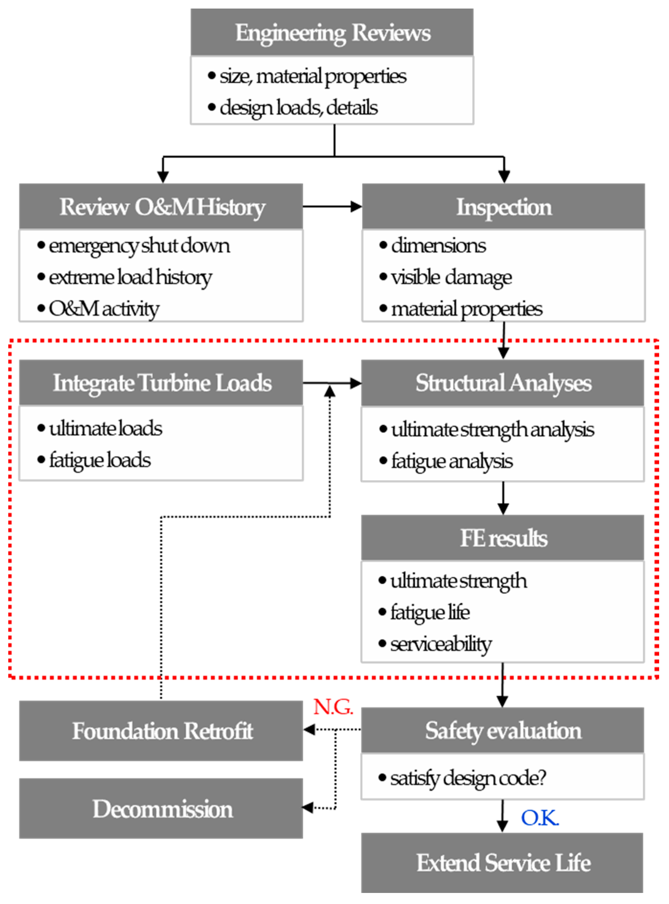
3.1. Concrete Material Test
In order to evaluate concrete material properties, destructive testing by core drilling as well as non-destructive testing by Schmidt hammer was carried out. However, the concrete properties obtained by destructive testing were judged to be more accurate, and this property was used in structural safety evaluation of this paper. Alternatively, if concrete core drillings are not available in the practical problem, the properties by non-destructive testing may be used.
First, concrete cores were collected for the foundation of an in-service wind farm located in Jeju of South Korea. A concrete core was collected for the foundation where the turbine was demolished due to some recent problem. In the same wind farm, multiple turbines with the same turbine and foundation are still in service. By using these concrete cores, concrete material safety including compressive strength, modulus of elasticity, and ultrasonic measurement were evaluated, as presented in
Figure 5. Three concrete cores were collected for each unit of the two foundations, having the same site, the same service life, and the same wind turbine. The material safety in terms of strength was evaluated using the average of the values measured from these cores. As a result of the material safety evaluation, it was found that the concrete compressive strength (f
m) of the foundation was maintained at a materially sound state, such as 39.3 to 41.9 MPa, which exceeded the design strength (f
d) of 30 MPa, as indicated in
Table 2. The material safety of concrete was evaluated as follows, and it was found that the concrete strength was 1.35 times higher than the design strength.
At this time, the concrete compressive strength by the destructive test (f
m) was utilized as a concrete material property in the ultimate strength evaluation by numerical analysis in
Section 3.2, so that the structural safety of the foundation reflecting the in-situ concrete condition could be evaluated [
3].
3.2. Ultimate Strength
Using the results of the material strength evaluation for the in-service foundation concrete, it was evaluated whether or not the ultimate strength of the foundation was satisfied for the current turbine load [
12,
13,
14,
15]. The ultimate strength was evaluated by numerical analysis by FE analysis program DIANA [
16] reflecting the in-situ concrete compressive strength indicated in
Table 2. DIANA software has advantages in the nonlinear analysis of complex concrete members such as onshore wind foundations since it has various modeling and physical property modules for the concrete members. The yield strengths of the anchor ring and reinforcing rebar were 240 and 400 N/mm
2, respectively. The structural members constituting the foundation such as the concrete, reinforcement, and anchor ring were modeled as realistically as possible [
17], as shown in
Figure 6. Concrete foundations and anchor rings were modeled as solid elements, and reinforcing bars were modeled using embedded reinforcement elements. The tower was not modeled separately, but only the extreme load acting on the bottom of the tower was applied to the top of the anchor ring, as presented in
Figure 4a. For the concrete material model, the total strain crack model considering the compressive behavior and the tensile behavior (fracture energy-based) was used.
For the evaluation of the bearing capacity of the soil layer, the soil layer of the bottom of the foundation was modeled using a compressive spring [
3,
12], as presented in
Figure 6, for which the reaction force is to be subjected to the foundation bottom only when the foundation and the ground are in contact with each other, as presented in
Figure 4a. The ultimate turbine load for the structural safety evaluation of the foundation was provided by the turbine company, and the specifications of the foundation were provided by the authority of the wind farm.
At first, critical points for each structural member of the concrete, reinforcement, anchor ring were selected through pre-analysis. As a result of pre-analysis, critical points of the tension part of the foundation were distributed around the concrete crushing cone resisting pull-out from the anchor ring plate, as presented in
Figure 6 and
Figure 7a. Also, critical points of the compression part of the foundation were distributed around the concrete crushing cone that resists compaction under the anchor ring plate, as presented in
Figure 6 and
Figure 7a. Then, the maximum stresses in these critical points were evaluated by applying the ultimate turbine load. The structural safety for the ultimate strength was evaluated by comparing the maximum stresses (f
max) at critical points and the yield strengths (f
y) of each material.
As a result of the evaluation, as indicated in
Figure 7 and
Table 3, the maximum stress ratios (actual strength/design strength) for each structural member such as concrete, reinforcement, anchor ring were 0.49 or less, indicating that ultimate strength safety was maintained.
3.3. Fatigue Life
Fatigue life was evaluated by performing fatigue analysis by FE analysis program ANSYS [
18], which is widely used for fatigue analysis of various structures including the concrete members, using the equivalent fatigue load of the in-service wind turbine. In the DNV-GL guidelines [
19] for fatigue life, it is recommended to use a fatigue load corresponding to negative inverse slope m = 3 of the S-N curve when the number of fatigue load cycles is 10
7 or less. Also, it is recommended to use a fatigue load corresponding to negative inverse slope m = 5.0 of the S-N curve when the number of fatigue load cycles exceeds 10
7 [
19]. The purpose of this section is to evaluate the overall fatigue life of the in-service foundation. Therefore, it was evaluated by applying a fatigue load corresponding to negative inverse slope m = 3.0 until 20 years because it was subjected to a cycle fatigue load of 10
7 or less until 20 years. Fatigue life after 20 years was evaluated by applying a fatigue load corresponding to the negative inverse slope m = 5.0, as indicated in
Table 4.
The S-N curve for each material used in fatigue life evaluation is provided in
Figure 8. In the case of concrete, the S-N curve of the FIB model [
18,
20] was applied, and in the case of steel, the S-N curve of A36 steel with a yield strength of 40 MPa, which is the same as the reinforcing bar (HD25 to 29) applied to the aged concrete foundation, was applied [
18]. The average fatigue stress theory for each structural member to evaluate fatigue life is as follows. For the steel, Goodman’s theory [
18,
21] is applied to obtain stable results for low-ductility metals. For the concrete, the Soderberg theory [
18,
22,
23] is applied, which is known to be more conservative than the Goodman theory and suitable for brittle materials such as the concrete.
In this paper, fatigue life was evaluated using the concept of the “Fatigue Safety Index [
18]” in the corresponding year, represented by the following equation, where if the fatigue safety index is 1.0 or over, it means that it is safe for fatigue life.
The service life used for fatigue life evaluation was targeted at two cases: the service life to now (16 years) and the service life up to 40 years. The fatigue load corresponding to m = 3 was applied in the fatigue life evaluation for the service life up to now, and the fatigue load corresponding to m = 5 was applied to the fatigue life evaluation up to service life 40 years. The fatigue safety index of the foundation was evaluated for each of the most critical areas for tension and compression for each structural member, respectively, as presented in
Figure 9. As a result of fatigue life evaluation, the minimum fatigue safety indexes of steel and concrete for the equivalent fatigue load of m = 3.0 were 2.93 and 1.88, respectively, as presented in
Figure 10. The minimum fatigue safety indexes for the equivalent fatigue load of m = 5.0 were 1.76 and 1.21, respectively, as presented in
Figure 11. In summary, the in-service foundation showed that the fatigue safety index of up to 40 years of service life was 1.0 or higher for the in-service turbine fatigue load, thereby securing a fatigue life of 40 years or more.
3.4. Soil Resistance, Overturning, and Sliding
(1) Soil resistance
The onshore wind foundation should be installed on a good soil layer, and it is important to ensure the bearing capacity of the soil layer against the maximum vertical load acting on the foundation ground. In other words, the vertical ground reaction force generated on the bottom of the foundation due to the ultimate turbine load should lie below the allowable bearing capacity of the foundation ground [
13,
14,
15].
In this paper, the soil resistance of foundation soil layer was evaluated by comparing the maximum vertical load (q
max) generated at the bottom of the foundation with the allowable bearing capacity (q
a) of the foundation ground calculated by the design criteria [
13,
14,
15], as indicated in Equation (4). The targeted ground condition of this study is soft rock (basalt), and the allowable bearing capacity of this soil layer is given as 200 kN/m
2 in the design condition.
As a result of the evaluation, the maximum vertical reaction force generated on the bottom of the foundation resulted in 74.1 kN/m2, and the allowable bearing capacity of the foundation soil layer was calculated to be 200 kN/m2 by design condition. Therefore, the maximum vertical reaction force generated on the bottom of the foundation due to the ultimate turbine load was estimated to be about 37% of the allowable bearing capacity of the foundation soil layer and the supporting resistance of the soil layer was evaluated to be sufficient.
(2) Overturning
Another important aspect of the safety of the onshore wind foundation is overturning. It is important to secure the overturning resistance to the maximum overturning moment generated in the foundation by the turbine load [
24]. In other words, the overturning moment generated on the bottom of the foundation due to the ultimate turbine load should lie below the allowable overturning capacity of the foundation [
13,
14,
15].
In this paper, the overturning safety of foundation was evaluated by comparing the maximum overturning moment (M
max) generated at the bottom of the foundation with the allowable overturning capacity (M
a) of the foundation calculated by the design criteria [
13,
14,
15], as indicated in Equation (5). The allowable overturning capacity means the resistance to overturning is only from the self-weight of the foundation and it can be easily calculated by multiplying the total self-weight of the foundation and the overturning moment arm length.
As a result of the evaluation, the maximum overturning moment generated on the bottom of the foundation resulted in 10,473 kN-m and the allowable overturning capacity of the foundation was calculated to be 21,881 kN-m by the design criteria. Therefore, the maximum overturning moment generated on the bottom of the foundation due to the turbine load was estimated to be about 48% of the allowable overturning capacity of the foundation and the overturning safety of foundation was evaluated to be sufficient.
(3) Sliding
It is important to secure the sliding resistance of the foundation against the lateral load generated by the ultimate turbine load. The sliding of the onshore wind foundation resists only by the frictional force on the bottom of the foundation. Therefore, the maximum shear force generated on the bottom of the foundation due to the ultimate turbine load should lie below the allowable shear (frictional) force of the foundation ground [
13,
14,
15].
In this paper, the sliding safety of foundation was evaluated by comparing the maximum shear force (V
max) generated at the bottom of the foundation with the allowable shear (frictional) force (V
a) of the foundation ground calculated by the design criteria [
13,
14,
15], as indicated in Equation (6). The targeted ground condition is soft rock (basalt), and the allowable shear (frictional) force of this soil layer is given as 2722 kN (including safety factor 1.2) in the design condition.
As a result of the evaluation, the maximum shear force generated on the bottom of the foundation resulted in 266 kN and the allowable shear (frictional) force of the foundation was calculated to be 2722 kN by the design criteria. Therefore, the maximum shear force generated on the bottom of the foundation due to the ultimate turbine load was estimated to be about 10% of the allowable shear (frictional) force of the foundation and the sliding safety was evaluated to be sufficient.
3.5. Summary of Structural Safety Evaluation
As a result of structural safety evaluation for the aged onshore wind foundation, it was found that the existing foundation satisfies structural safety such as ultimate strength, fatigue life, and serviceability, as well as material safety in strength for the in-use turbine load, as provided in
Table 5. It was found that the material strength of the foundation had a safety margin of 35%, the ultimate strength of about 51%, fatigue life of about 20 years or more, and stability (overturning and sliding) of about 52%. It is considered that the result of structural safety evaluation of this study was partly contributed by the review of the limit state design method currently in use because the design method applied when it was first constructed is not known. In particular, the fatigue life is the most important item to determine the service life extension of the foundation because the foundation is continuously damaged by turbine loads depending on the service life [
24,
25]. As a result of evaluating the fatigue life of the turbine load, it has been shown that it has a fatigue life of 40 years or more, so that service life can be extended.


