Article

Effect of the Soft and Hard Interbedded Layers of Bedrock on the Mechanical Characteristics of Stabilizing Piles

1
Faculty of Engineering, China University of Geosciences (Wuhan), Wuhan 430074, China
2
School of Civil and Environmental Engineering, UNSW, Sydney, NSW 2052, Australia
*
Author to whom correspondence should be addressed.
Appl. Sci. 2020, 10(14), 4760; https://doi.org/10.3390/app10144760
Submission received: 28 May 2020 / Revised: 25 June 2020 / Accepted: 6 July 2020 / Published: 10 July 2020
(This article belongs to the Section Civil Engineering)

Abstract

:
In this paper, the mechanical characteristics of stabilizing piles embedded in layered bedrocks are studied both experimentally and numerically. The influence of soft and hard interbedded layers in the structure of the bedrock on the mechanical characteristics of stabilizing piles is particularly investigated. The discrete element method is used to numerically investigate the response of the stabilizing piles embedded in composite and inclined bedrocks. The simulation results and comparison with experimental data are presented to demonstrate the effectiveness and accuracy of the discrete element model. As the dip angle of the soft/hard interbedded bedrock layers increases from 0° to 45°, it is observed that the displacement of the embedded section of the stabilizing pile increases and reaches the maximum displacement at 45°. In the range of 45° to 75°, the influence of the dip angle of the layered bedrock on the displacement of the embedded section of the pile is gradually reduced.

1. Introduction

Landslides widely occur in the Three Gorges Reservoir Region in China [1,2,3,4]. Stabilizing piles, acting as retaining structures subjected to lateral loading, are widely used to improve the stability of the slopes and prevent their excessive movements [5,6,7]. The majority of studies in this field have, however, focused on the analysis of stabilizing piles embedded in homogeneous bedrock [8,9,10,11,12,13,14,15,16,17]. From the in situ monitoring and testing of piles [18,19,20,21,22], researchers realized that the bedrock in the region are mainly multilayered rather than homogenous. This has later been validated by the exploration of the landslide sites [23,24].
During the past two decades, several researchers studied the response of stabilizing piles embedded in multilayered media subjected to horizontal movements. Martin and Chen [25] numerically studied the effects of a weak and liquefied soil layer beneath the slope on the response of piles and pile groups using FLAC3D software which is a simulation software developed by Itasca company. Conte et al. [26] conducted a study on the response of reinforced concrete piles under horizontal loading in multilayered soils composed of silty sand and sandy silt. Salgado et al. [27] proposed a semi-analytical method for the analysis of pile groups embedded in multilayered elastic soils. Lei et al. [28] studied the response of laterally loaded piles in multilayered elastic soils using a separation-based continuum model. Laminar rock mass structures have generally been modeled as equivalent homogeneous or horizontally layered bodies in the analysis of stabilizing piles [29].
The Jurassic formation is most widely distributed in the slopes of the Three Gorges Reservoir area, and the number of landslides developed in this formation accounts for 67% of the total landslides in the reservoir area. There are a large number of soft (mudstone) and hard (sandstone) layers interbedded in the structure of the bedrock in the Jurassic formation in the Three Gorges Reservoir. The formation structure is different from the homogeneous rock mass, and a shear stress concentration occurs frequently under gravity loads, resulting in the overall failure of the weak layer. Therefore, it is extremely easy for the formation to slide, which leads to landslide disasters that urgently need to be controlled. Compared with the homogeneous sliding bed, the soft and hard interbedded layers change the rock mass properties of the sliding bed, and the mechanical and deformation characteristics of the stabilizing piles are inevitably affected. At present, there is a lack of landslide stability evaluation methods and control measures for slippery formations; generally, conventional stabilizing pile design methods were used to control landslides. However, the influence of the rock mass structure and the soft and hard rock layer properties on the mechanical and deformation characteristics of the piles were not considered comprehensively. The selections of the parameters had large randomness, and the analysis results obtained were likely to be inaccurate or even wrong. It is essential to study the effect of the soft and hard interbedded layers of bedrock on the mechanical characteristics of stabilizing piles.
Conducting experimental analysis is an effective way to investigate the behavior of stabilizing piles [2,3,6,30]. Several laboratory physical model tests [31,32] and centrifuge model tests [33,34] have been performed to study the response of stabilizing piles in homogenous slopes. Tang et al. [35] conducted large-scale physical model tests based on a colluvial landslide to determine the variation of pressure along the lengths of anti-sliding piles. Li et al. [4] examined the behavior of stabilizing piles at different locations in the bedrock with a hard upper layer and a weak lower layer. The experimental analysis is conducive to highlighting the main contradictions in the test process, and it is easy to grasp the inherent connection of the discovered phenomenon, but the test period is long, the operation is complicated, and the related cost is high. Hence, numerical simulations have widely been conducted for pile-slope interaction analysis [7,29,36,37,38,39,40].
In this paper, the mechanical characteristics of stabilizing piles embedded in soft and hard interbedded bedrocks are both experimentally and numerically studied, and the influence of the weak and hard interbedded layers in the sliding bed on the response of the stabilizing piles is investigated. A large number of field surveys and data collection related to the physical and mechanical behavior of sandstone, mudstone, and typical structures in the Three Gorges Reservoir are utilized in this study. The influence of the discontinuous sliding bed on the force and deformation characteristics of the piles is particularly studied. The displacement distribution function for the embedded segments of the stabilizing pile is obtained for both soft and hard interbedded layers and different dip angle of the sliding bed, providing a theoretical basis for the optimal design of the stabilizing piles.

2. Laboratory Investigation of the Effect of a Landslide on Stabilizing Piles

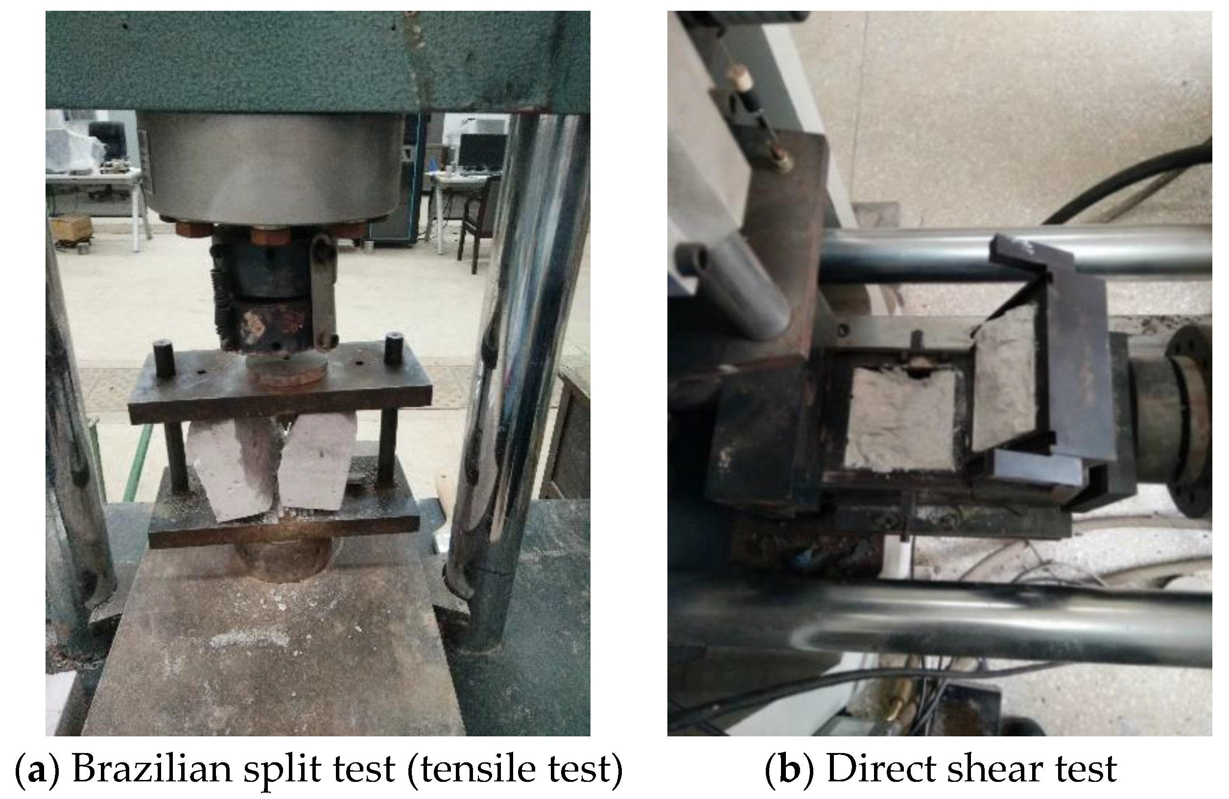
2.1. Material Parameters

The Three Gorges reservoir area starts from Zigui County in Yichang City and ends in the vicinity of Jiangjin District, Chongqing. The terrain within the reservoir area is mainly hilly, the mountains are undulating, the water system is vertical and horizontal, the length of the mainstream is approximately 1300 km, the total length of the tributaries is over 3600 km, and the water body is enriched. A typical slippery sandstone-mudstone interbedded formation is common in the reservoir area, which creates conditions for the breeding of landslides and dangerous rock masses. After the Three Gorges dam was impounded, the rising water level accelerated the evolution of geological disasters in the area. According to statistics, there are more than 550 landslides and 120 collapses with a total volume of over 3 billion cubic meters on both sides of the main tributaries. Soft and hard interbedded formations are prone to landslides, and even if the dip angle is small or the terrain is slightly slow, the instabilities of the bedding landslide and the tangential landslide, which are extremely harmful, will also have occurred.
The bedrock in the Three Gorges Reservoir is mainly composed of sandstone and mudstone belonging to the Suining Formation of the Upper Jurassic. The Majiagou landslide is situated on the left bank of the Zhaxi River, a tributary of the Yangtze River. The landslide is approximately 550 m long, 180 m wide and 24 m high. The main lithology of Majiagou landslide is the interbedded layers of feldspar-quartz fine sandstone and silty mudstone belonging to the Suining Formation of the Upper Jurassic which are very typical soft and hard interlayers of the Jurassic in the Three Gorges reservoir area. The material parameters of the bedrock and the shear strength parameters of the discontinuities are presented in Table 1 and Table 2, respectively [41,42,43]. In the tables, ρ is the density, E is the elastic modulus, μ is the Poisson′s ratio, c is the cohesion, and φ is the internal friction angle.
Most of the discontinuities of mudstone are smooth, undulating and unfilled, while those of sandstone are rough, flat and unfilled. In the shear test of mudstone, when the normal stress is small, the climbing effect would be appeared; when the normal stress is large, the gnawing effect would be appeared, thus the shear strength of the mudstone discontinuities will be increased [41].

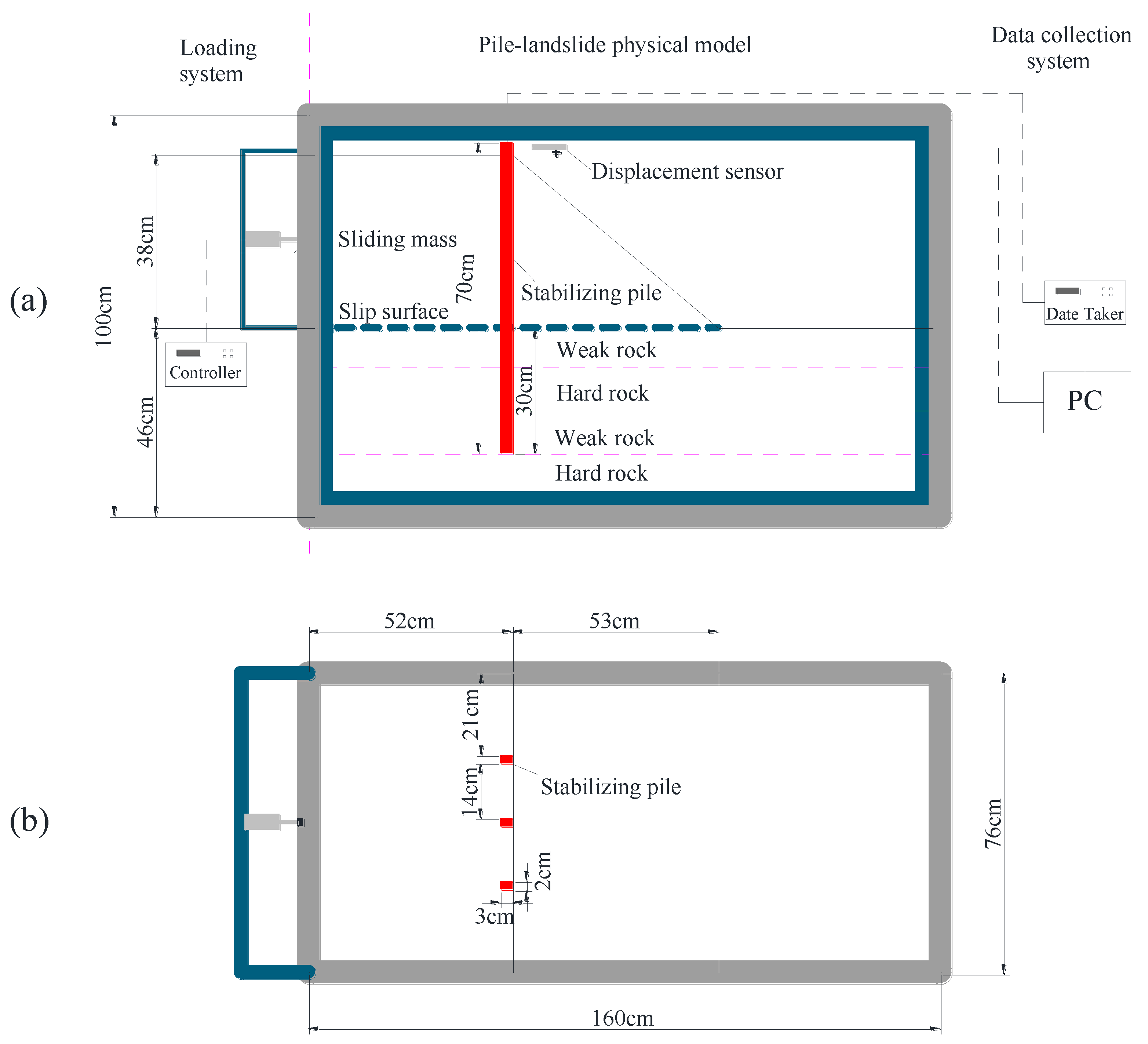
2.2. Experimental Model

The landslide model is designed based on the physical and mechanical parameters of the bedrock and discontinuities. On the trailing edge of the landslide, a horizontal thrust is applied to study the influence of the force and deformation characteristics of the landslide bed on the block.
The testing system consists of three parts, i.e., the data acquisition device, the frame of the landslide model and the loading device. The horizontal load is applied by a jack. The displacement of the pile head and the force in the stabilizing pile under different conditions are monitored. The layout of the test model is shown in Figure 1, and the frame diagram is shown in Figure 2. The testing device contains the sliding body, the loading device, the sliding bed, the stabilizing pile, and the monitoring equipment.
The frame dimensions are 160 cm × 76 cm × 100 cm (see Figure 2). One side of the frame is an 8 cm thick tempered glass, so continuous monitoring of deformation of the sample is a convenient process in the experiment. The size of the stabilizing pile is 2 cm × 3 cm × 70 cm, and the embedded length of the pile is 30 cm.
The jack was used to load the trailing edge of the sample. The loading was divided into five stages, and the standard procedure for each stage of the loading was to move the trailing edge by 3 cm. The thrust at the trailing edge of the sample was measured by the pressure sensor placed at the top of the jack during the loading process. The strain of the pile was measured using strain gauges. Fourteen strain gauges were used along the length of the pile and seven gauges were used on each side with a 10 cm spacing between them, as shown in Figure 3.
The sliding bed is prepared in 4 different rock layers and the sliding body is a whole part. In the process of the experimental model, each layer of sliding bed is casted by one-time casting. The bottom rock layer is casted according to the experimental scheme, and it needs to be emphasized that each rock layer should be cured with four days to obtain the basic strength. Subsequently, the stabilizing pile is fixed on the bottom rock layer, then the second layer, the third layer and the fourth layer were placed respectively. Finally, the sliding body was placed.
To minimize the boundary effects on the test results, three stabilizing piles were used in the model, and the top displacement of the middle pile was measured through the dial indicator. The arrangement of the stabilizing pile and the dial indicator is shown in Figure 4.

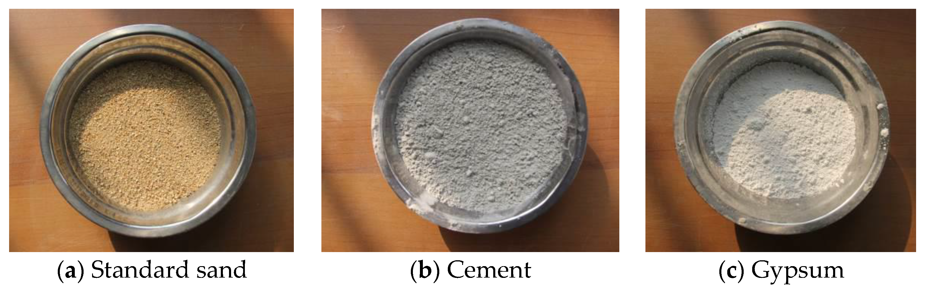
2.3. Production of the Experimental Materials

To produce the artificial soft rock, hard rock and sliding body similar to those in the field, a series of experiments were carried out. The soft and hard rock samples, with dimensions of 7 cm × 7 cm × 7 cm, were cured for 30 days, and the material and strength parameters of the samples were obtained by conducting the tensile test and the direct shear test (Figure 5). Based on the field parameters, the proportion of the materials was adjusted to the obtained optimum ratio. The standard ratio of the sand to clay is 1:1 for the sliding body, the hard rock was produced from sand, cement, gypsum, and water with the proportion of 3:1:1:1, and the soft rock was produced with sand, cement, gypsum, and water according to the proportion of 9:1:1:2. Nylon rods made of polyethylene were used to produce the piles. The raw materials of the model are shown in Figure 6, and their physical and mechanical parameters are presented in Table 3.

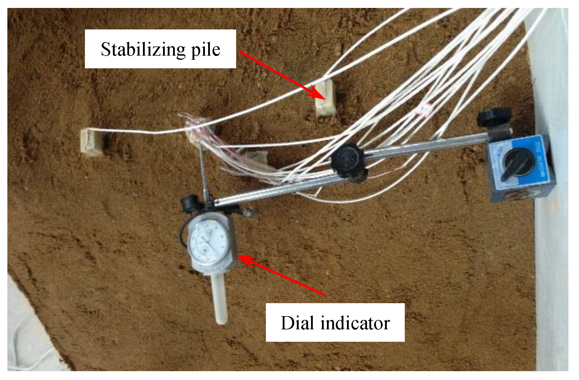
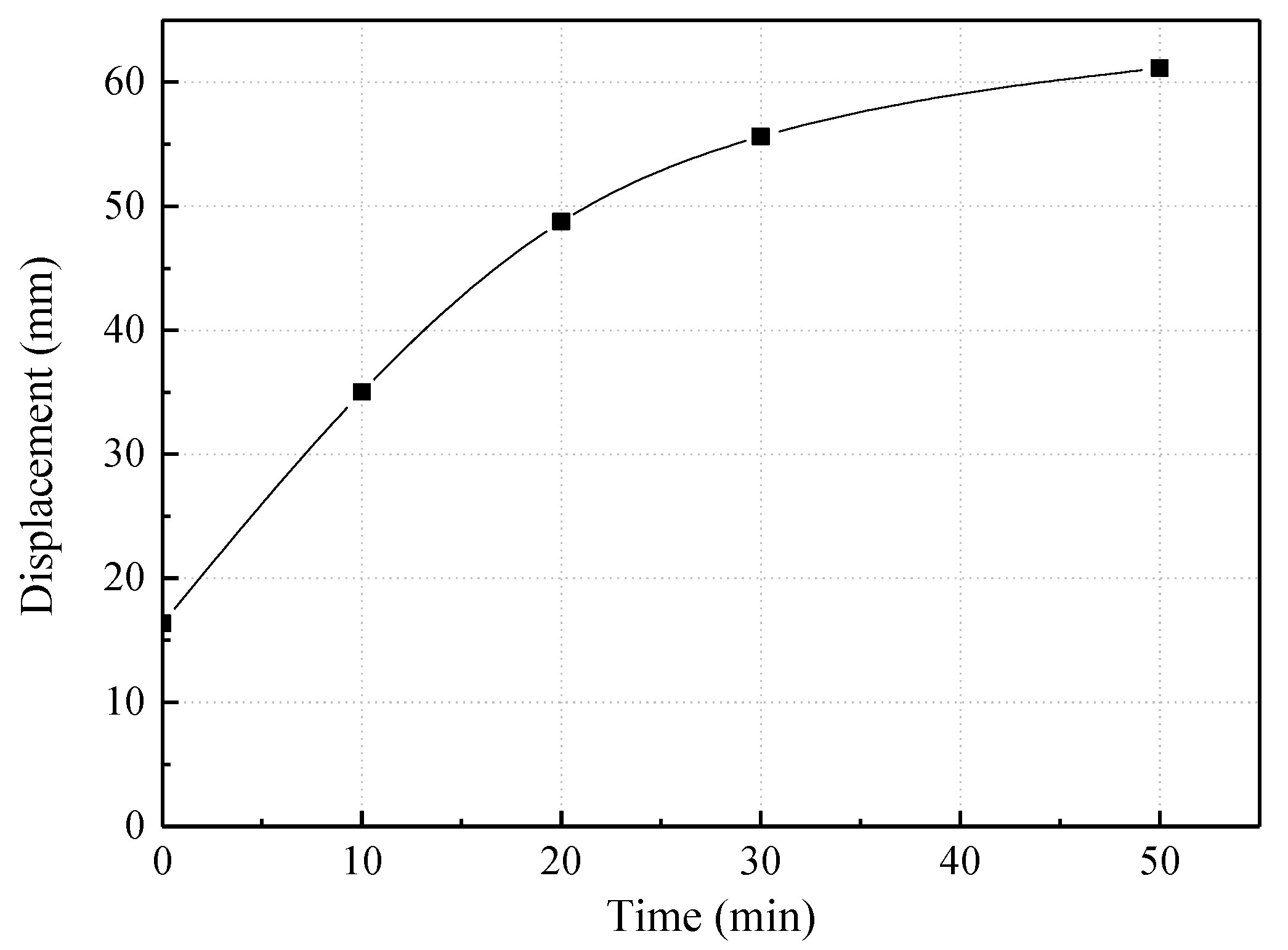
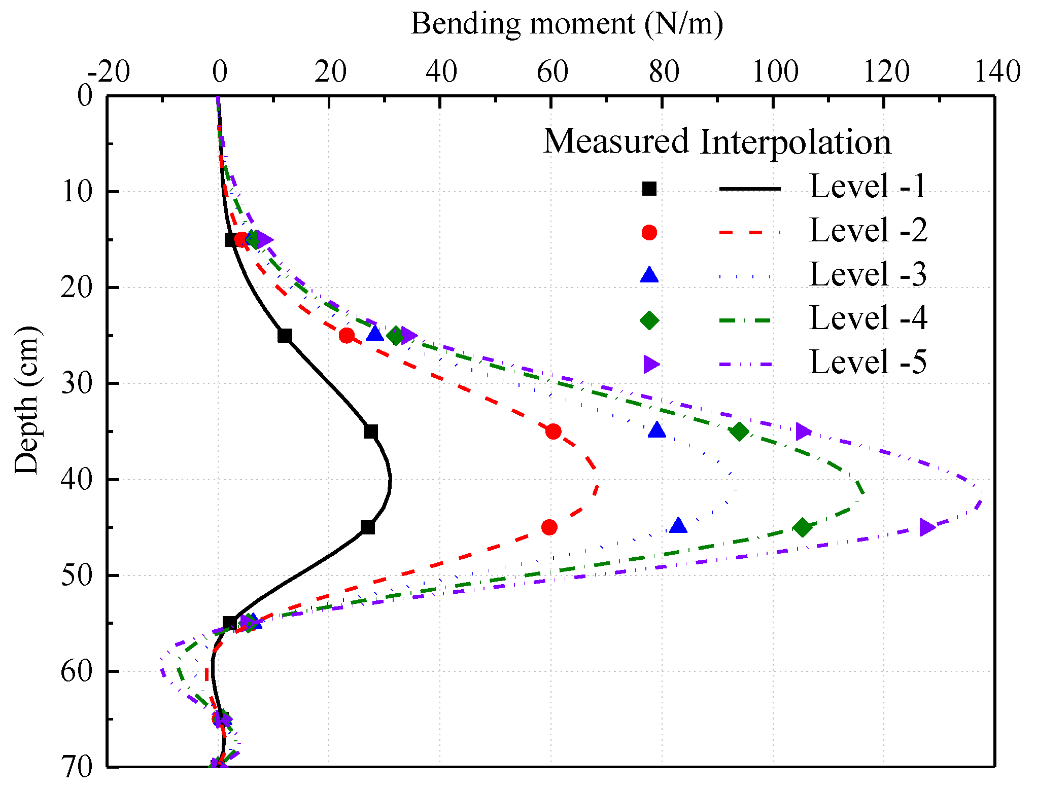
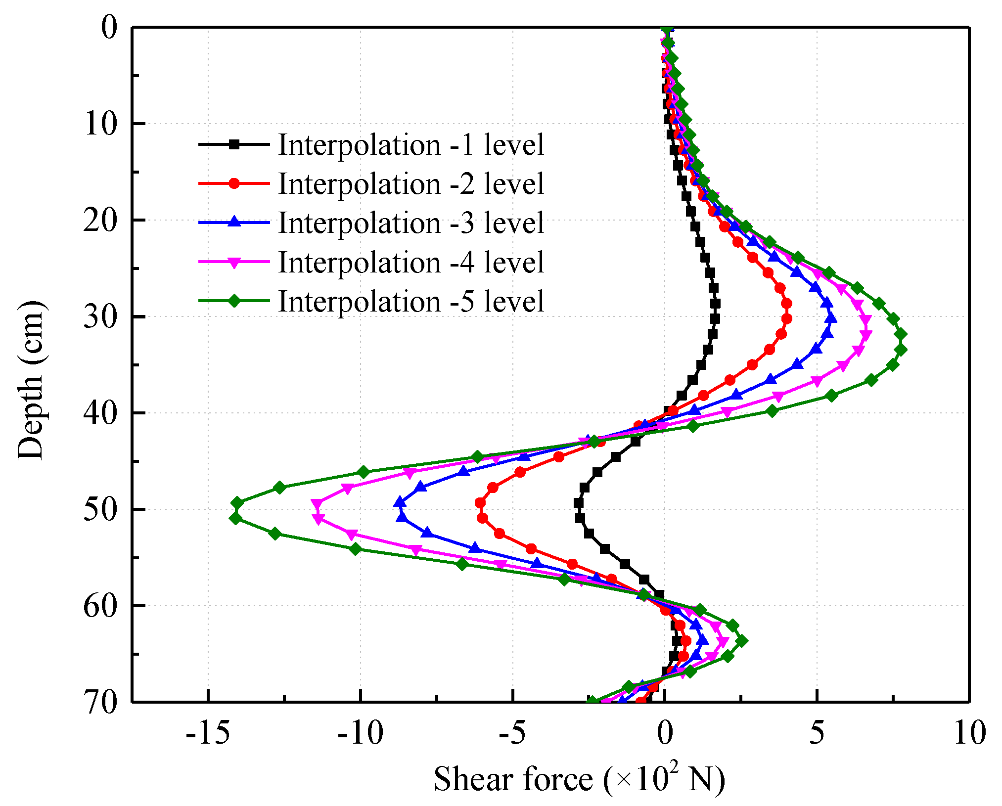
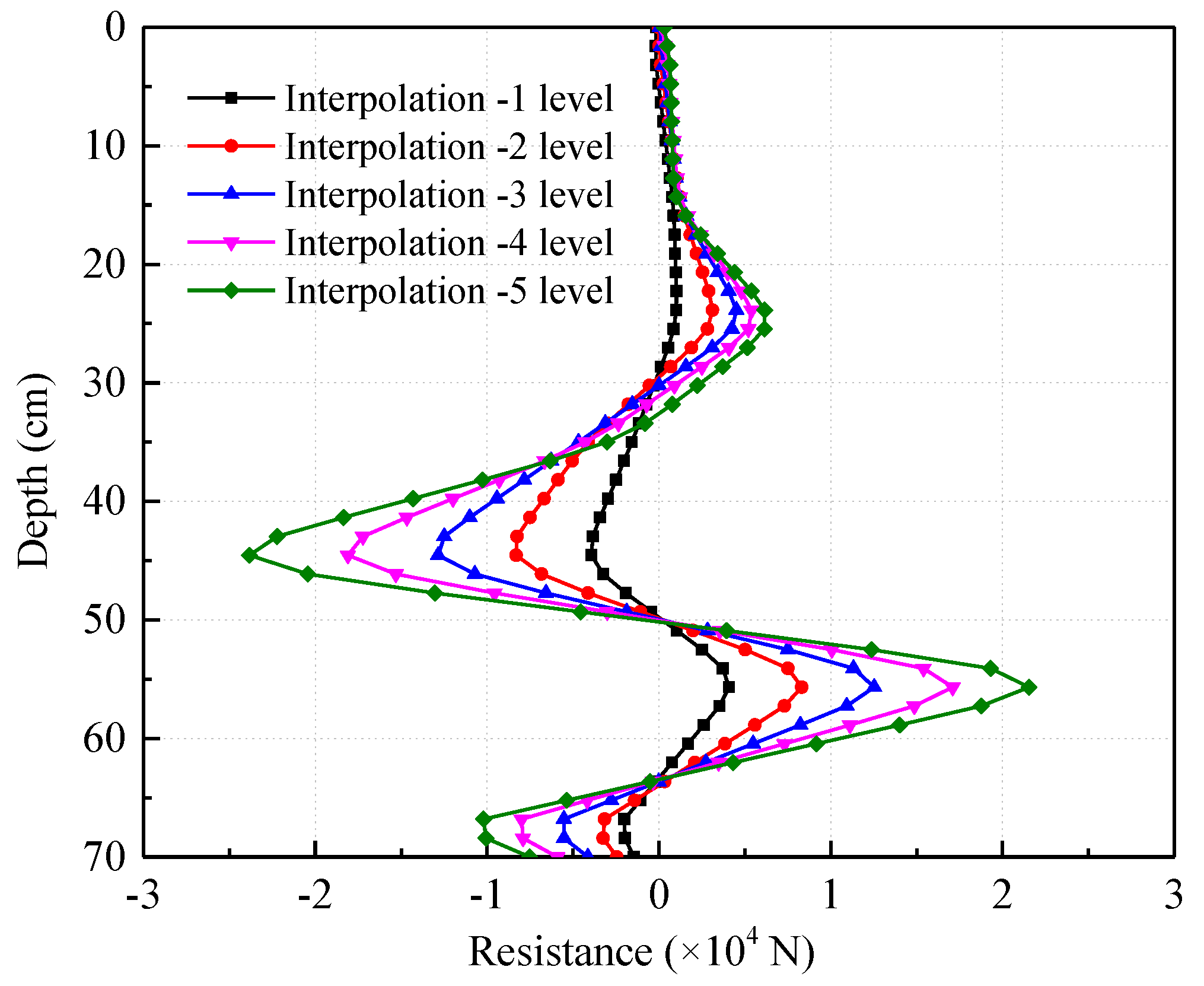
2.4. Analysis of the Test Model Results

The bending moment of the stabilizing pile in the physical model test is obtained through the pile body strain conversion. The bending moment at the corresponding measured point along the length of the pile can be calculated as:
M = W × E s × ( ε h ε q ) / 2 W = b h 2 / 6
where W is the section modulus in bending, and b, h are the section width and height of the pile, respectively. Es is the elastic modulus of the pile, which is considered 1.68 GPa in this study, and εh εq are the strains measured at the front and back of the pile, respectively.
The experiment was divided into five loading stages, starting at times 0, 10, 20, 30, and 50 min. The load remains constant for 10 min in the first, second and third stages, and given it is gradually difficult to apply load with the load increasing and the applied load is instable, the interval time is approximately set to 20 min in the fourth stage [41,44]. By monitoring the strain along the length of the pile, the bending moment can be determined using Equation (1), see Figure 7.
The pressure sensor monitored the values applied to the sliding body, as shown in Figure 8. By using the indicator monitoring of the top displacement of the middle stabilizing pile, the displacement of the mid-pile head was recorded when the load at each stage reached the stable condition, as shown in Figure 9.
Based on the distribution of the bending moment, the distribution of the force and the pile deflection curve can be determined. According to the mechanics of materials, the soil resistance distribution p(x), the torsion y(x) and the shear force Q(x) in terms of the moment M(x) can be defined as:
y ( x ) = 1 E I M ( x ) d x 2
Q ( x ) = d M ( x ) d x
P ( x ) = d M 2 ( x ) d x 2
Using the cubic spline curve interpolation method, the distribution of the bending moment along the length of the pile was obtained for different loading stages (Figure 10). Based on the bending moment equation M(x), the shear force distribution Q(x) can be calculated from the first-order derivative of M(x) (Figure 11), and the soil resistance distribution function can be obtained from the second-order derivative (Figure 12).
The distribution of the moment is obtained by using MATLAB (cubic spline interpolation). Through the first and second derivation of the bending moment, the distribution of the pile shear force and the distribution of the geotechnical resistance were obtained, respectively, and the displacement distribution of the pile body was obtained from the second integral of the bending moment.
The displacement of the top pile is in accordance with the measured values (Figure 13), while the increase of the load classification, the point of the shear force that is zero, gradually moves down (Figure 11). It is also illustrated that the point of the maximum moment value gradually moves downward. The results illustrate that the loading ways and time should be considered in the design of stabilizing piles.

3. Numerical Modeling and Comparison with Experimental Results

The sliding bed simulated is a composite layered rock mass with discontinuities. The discrete element method, suitable for the simulation of discontinuous media, is used for the three-dimensional numerical modeling of piles and rock. The numerical model is established using 3DEC with the same dimensions as the test model (Figure 14). The ideal elastoplastic model (cons = 2) was selected as the constitutive model of the rock and soil. The Mohr–Coulomb Failure Criterion was chosen as the failure criterion of the rock and soil, and the Coulomb sliding failure model (jcons = 1) was used as the rock structure plane constitutive model. The boundary conditions of the model include horizontal constraints imposed by the horizontal and vertical sides, fixed constraints imposed by the bottom boundary plane of the model, and an unrestrained upper boundary surface. The rear edge of the sliding body applies a leftward (negative x-axis) uniform distribution of horizontal load to the upper part of the stabilizing pile.
According to the pressure loading method shown in Figure 8, the mechanical parameters are the same as Table 3. The bending moment distribution for the middle stabilizing pile is shown in Figure 15. It is observed that the numerical results are in good agreement with the experimental test results, indicating the reliability of the model.

4. Numerical Study Considering the Presence of the Soft and Hard Interbedded Bedrock Layer

4.1. Model Establishment and Parameter Selection

To highlight the influence of the rock joint occurrence of the sliding bed against the stress and deformation characteristics of the embedded section of the sliding pile, the numerical model is simplified (Figure 16). The simplified stabilizing pile was only considered with a horizontal load caused by the self-weight of the soil. The entire model is 60 m long, 30 m wide and 30 m high; the stabilizing pile size is 2 m × 3 m × 23 m, the inclination of the sliding surface is 90°, and the dip angle of the sliding surface is 6°. The constitutive model, boundary conditions and mechanical parameters of the rock and soil used in the simulations are the same as those of the experimental model.

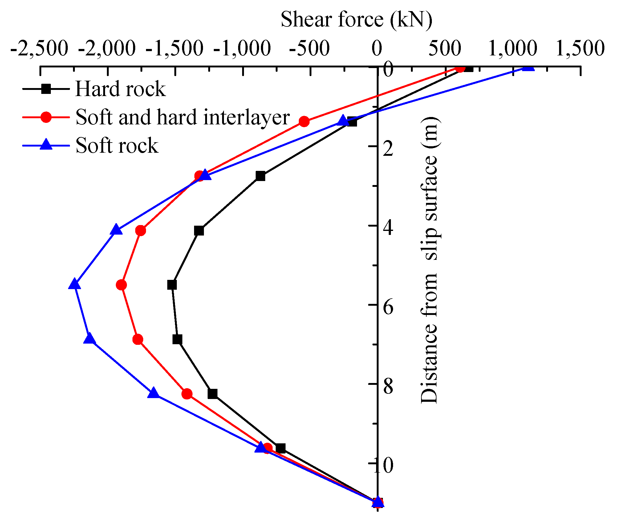
4.2. The Influence of Different Lithology Bedrock Layers on the Stabilizing Pile

The distributions of lateral displacements along the stabilizing pile embedded in different bedrocks, i.e., a homogeneous soft rock, a soft and hard rock interlayered and a homogeneous hard rock, are shown in Figure 17. The existence of the soft bedrock layer makes the displacement of the stabilizing pile larger but less than that of the homogeneous soft rock. When the sliding bed is a homogeneous hard rock, the displacement of the stabilizing pile at depth of 9 m is equal to 0, indicating that the embedded section of the stabilizing pile is too long. However, the larger embedment length in the interlayered and homogeneous mudstone is indeed more appropriate, illustrating that the reasonable embedded length of the stabilizing piles are affected by the heterogeneity of the landslide rock mass.
The bending moment and shearing force distributions along the embedded section of the stabilizing pile embedded in different bedrocks, i.e., a homogeneous soft rock, a soft and hard rock interlayered and a homogeneous hard rock, are shown in Figure 18 and Figure 19.
From Figure 18, it can be seen that the existence of the bedrock layer and the combination of soft and hard interlayers, results in the increase of the bending moment and shear force along the stabilizing pile, but the increase is less than that of the homogeneous soft rock. As the rock becomes softer, the bending moment and the maximum shearing force of the stabilizing piles gradually increase, and the position of the maximum bending moment point of the bending moment diagram gradually moves downward.

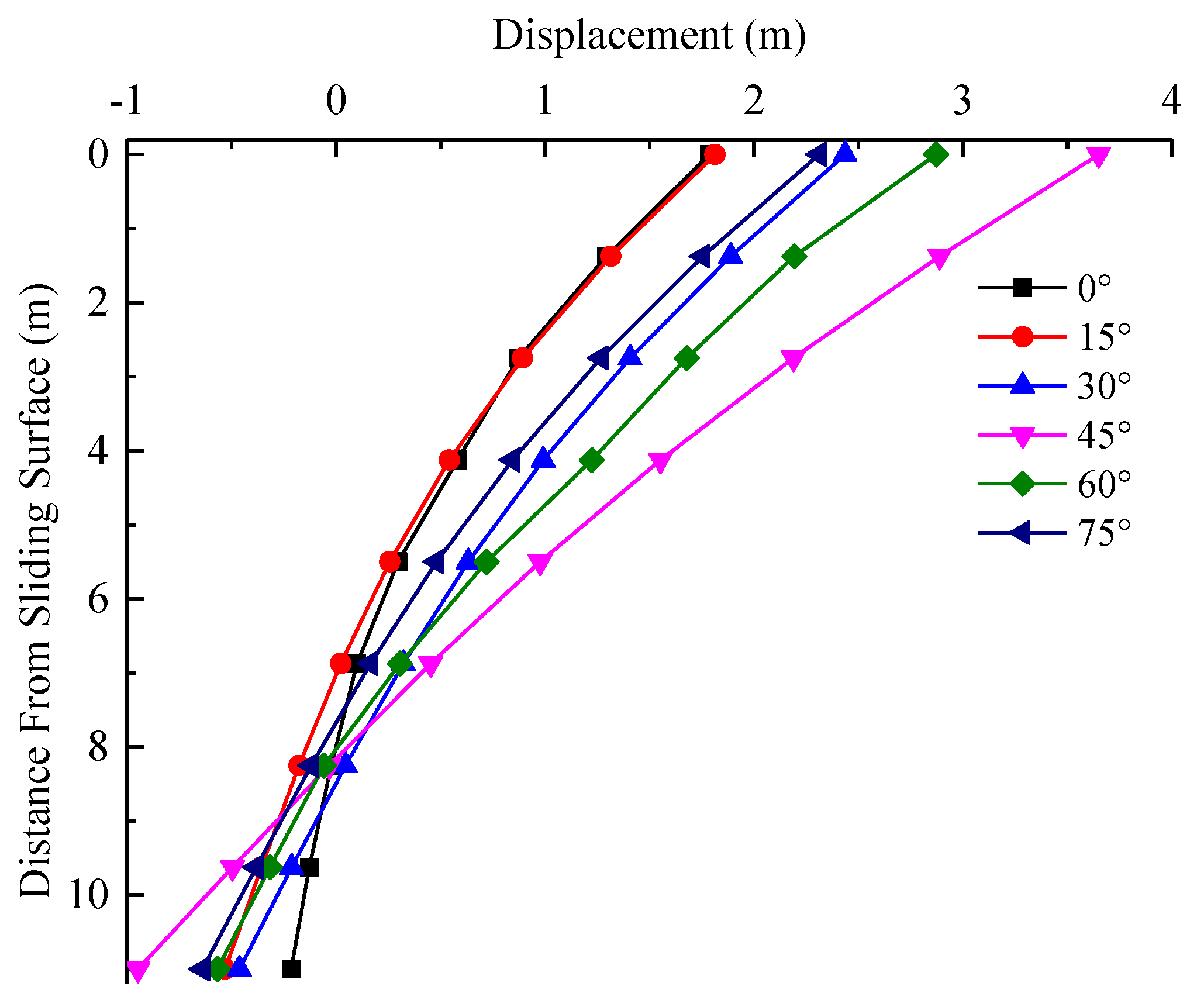
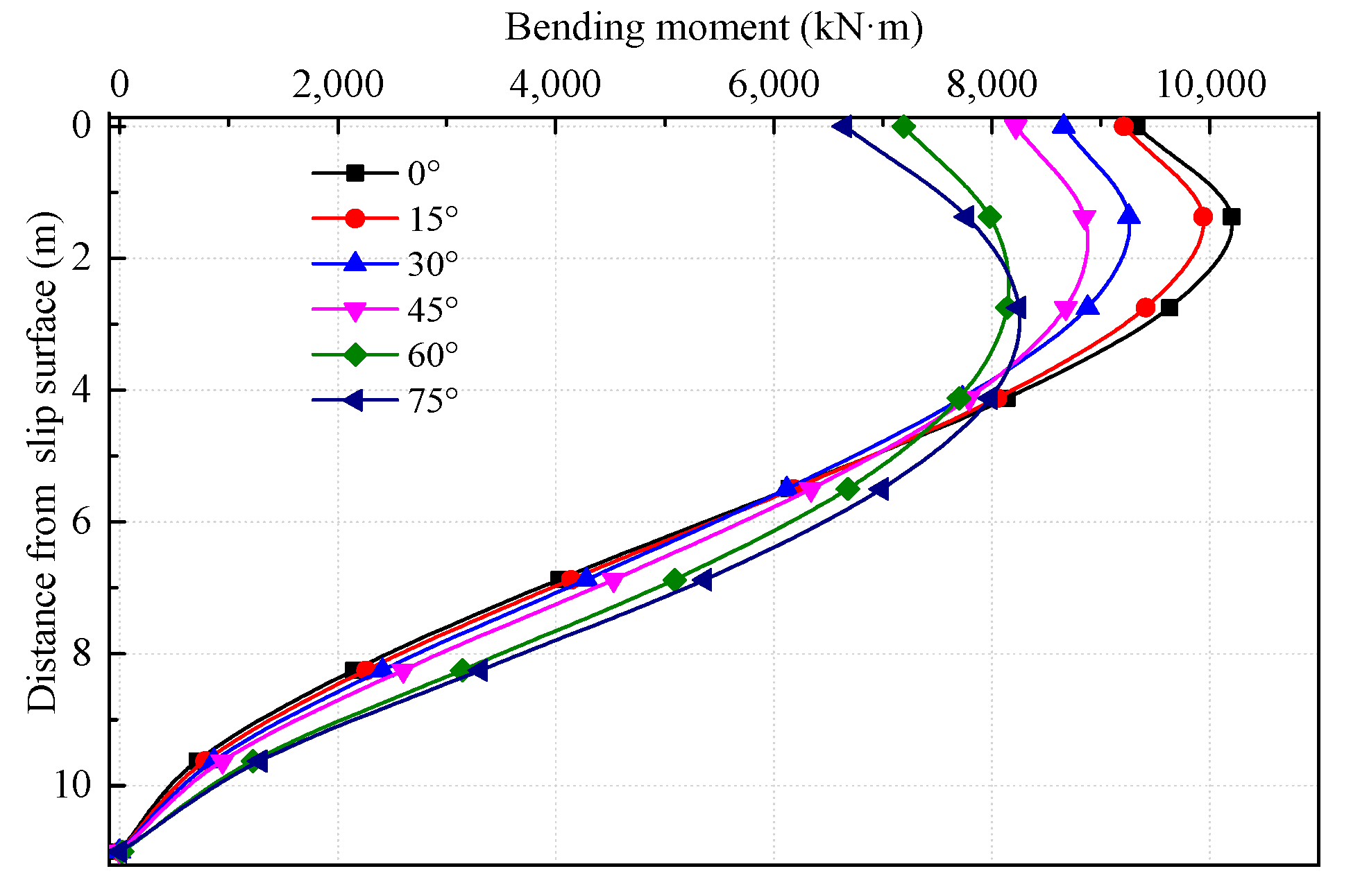
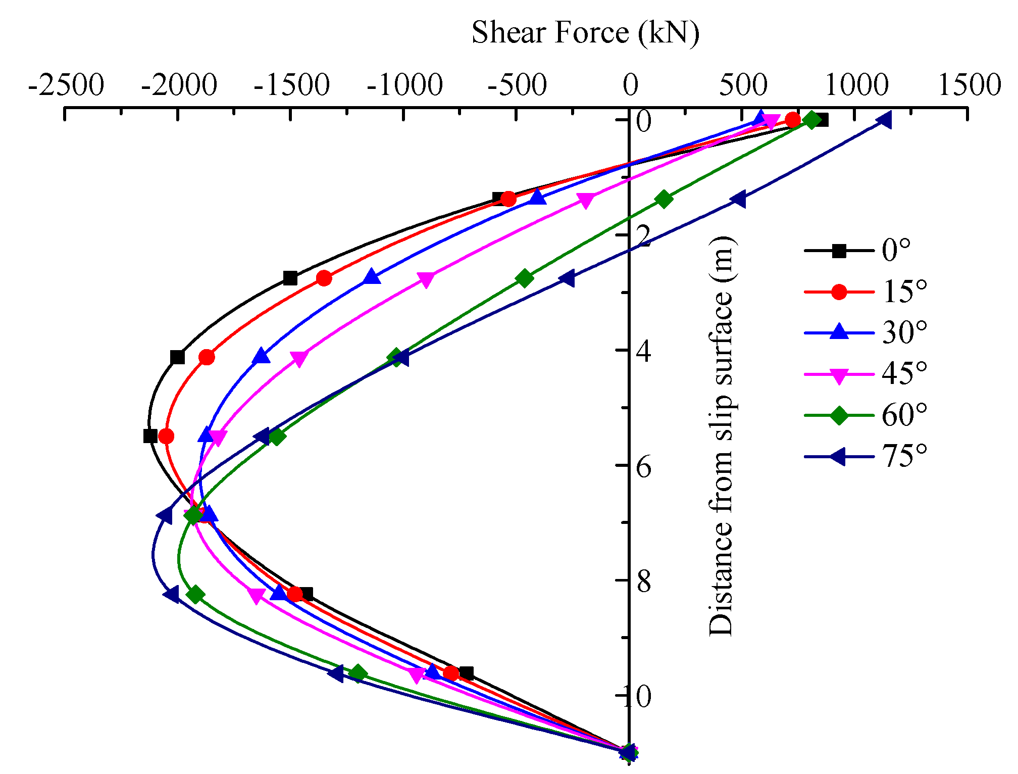
4.3. Effect of the Dip Angle of Soft and Hard Interbedded Bedrock Layer on Stabilizing Piles

To rigorously study the influence of the dip angle of soft and hard interbedded bedrock layer on the displacement and internal force of the embedded section of the stabilizing pile, 16 numerical simulations are performed with the layered bedrock dip angle increasing by 5° from 0° to 75°. Since the trends of the curves were consistent, to clearly display the trends, 6 typical curves were selected to plot. These simulation results are shown in Figure 20, Figure 21 and Figure 22.
To concretely study the influence of the dip angle of soft and hard interbedded bedrock layer on the displacement and internal force of the embedded section of the stabilizing pile, the bedrock layer inclination is 90°, and 16 sets of numerical experiments are performed when the layered bedrock dip angle increases by 5° from 0° to 75°. Considering that the trend of the curves is consistent, to display the trend of the curves more intuitively, 6 typical groups are selected for analysis. Numerical simulation results are shown in Figure 20, Figure 21 and Figure 22.
From Figure 20, as the dip angle of the soft and hard interbedded bedrock layer increases, the displacement of the embedded section of the stabilizing pile shows an increasing trend in the range of 0° to 45° and reaches the maximum displacement at 45°. In the range of 45° to 75°, the influence of the dip angle of the layered bedrock on the displacement of the embedded section of the slide pile is gradually reduced. The distribution of the bending moments and the shear forces of the stabilizing piles with different dip angles are shown in Figure 21 and Figure 22.
From Figure 21, as the dip angle of the soft and hard interbedded bedrock layer increases, the maximum value of the bending moment gradually decreases, and the position of the maximum moment point on the bending moment curve gradually moves downward. Above 4 m, the bending moment gradually decreases as the dip angle increases; however, under 4 m, the bending moment value gradually increases as the dip angle increases. From the shear force diagram, it is observed that as the dip angle increases, the point where the shear force is zero gradually moves downward, while the maximum shear force initially decreases and then increases. When the dip angle is less than or equal to 45°, the position of the maximum shear point remains unchanged, while the position of the maximum shear point moves downward when the dip angle is greater than 45°.

5. Conclusions

In this paper, the internal forces and deformations of stabilizing piles in soft and hard bedrock layer are studied by the pile-landslide physical model combined with the numerical model. The internal forces and displacements obtained from the numerical simulations are in good agreement with the field test results within the measured loading range. The numerical model can reasonably describe the joint action of the piles and rock reflected by the load test, and the numerical model can be used to better reflect the actual mechanical properties of the rock mass and the joint between the laterally loaded pile and the pile-perimeter rock mass effect. The existence of layered bedrock and the combination of soft and hard rocks lead to an increase in the bending moment and shear force of the stabilizing pile but less than that of the homogeneous soft rock. As the rock becomes softer, the bending moment and the maximum shearing force of the stabilizing piles gradually increase, and the position of the maximum moment point of the bending moment curve gradually moves downward.
(1) For the softer rock mass in terms of lithology, the existence of rock layers and the combination of lithologies increase the displacement, the maximum bending moment and the shear force of the embedded section of the stabilizing pile, but the amplitude of the growth is less than that of homogeneous soft rock. When the sliding bed is of homogeneous hard rock, the displacement of the stabilizing pile at 9 m is equal to 0, indicating that the embedded section of the stabilizing pile is too long, but the embedded length in the interlayered and homogeneous mudstone is indeed more appropriate, thus illustrating that the reasonable embedding length of the stabilizing piles is affected by the heterogeneity of the landslide rock mass.
(2) As the dip angle of the layer bedrock increases, the displacement of the embedded section of the stabilizing pile shows an increasing trend in the range of 0° to 45° and reaches the maximum displacement at 45°. In the range of 45° to 90°, the influence of the dip angle of the layered bedrock on the displacement of the embedded section of the slide pile is gradually reduced. As the dip angle of the bedrock layer increases, the maximum value of the bending moment gradually decreases, and the position of the maximum moment point of the bending moment curve gradually moves downward. Above 4 m, the bending moment value gradually decreases as the dip angle increases; under 4 m, the bending moment value gradually increases as the dip angle increases.

Author Contributions

Experimental design (M.D. and L.W.); experimental analysis (M.D. and B.S.); data were analyzed (X.D. and S.D.); numerical simulation (M.D. and Z.S.). All authors have read and agreed to the published version of the manuscript.

Funding

This research was funded by the National Natural Science Foundation of China [Grant No. 41372310 and 41877258], and the APC was funded by the National Natural Science Foundation of China [Grant No. 41877258].

Acknowledgments

This work was supported by the National Natural Science Foundation of China (Grant No. 41372310 and 41877258).

Conflicts of Interest

The authors declare no conflicts of interest.

References

  1. Li, C.D.; Wang, L.Q.; Jing, H.Y.; Liu, Q.T. Protection control scheme and evaluation of effects on pipeline crossing beneath landslide area. J. Pipeline Syst. Eng. Pract. 2013, 4, 41–48. [Google Scholar] [CrossRef]
  2. Zhu, H.H.; Shi, B.; Yan, J.F.; Zhang, J.; Zhang, C.C.; Wang, B.J. Fiber Bragg grating-based performance monitoring of a slope model subjected to seepage. Smart Mater. Struct. 2014, 23, 095027. [Google Scholar] [CrossRef]
  3. Zhu, H.H.; Shi, B.; Yan, J.F.; Zhang, J.; Wang, J. Investigation of the evolutionary process of a reinforced model slope using a fiber-optic monitoring network. Eng. Geol. 2015, 186, 34–43. [Google Scholar] [CrossRef]
  4. Li, C.D.; Wang, X.Y.; Tang, H.M.; Lei, G.P.; Yan, J.F.; Zhang, Y.Q. A preliminary study on the location of the stabilizing piles for colluvial landslides with interbedding hard and soft bedrocks. Eng. Geol. 2017, 224, 15–28. [Google Scholar] [CrossRef]
  5. Ashour, M.; Ardalan, H. Analysis of pile stabilized slopes based on soil-pile interaction. Comput. Geotech. 2012, 39, 85–97. [Google Scholar] [CrossRef]
  6. Zhu, H.H.; Ho, A.N.L.; Yin, J.H.; Sun, H.W.; Pei, H.F.; Hong, C.Y. An optical fibre monitoring system for evaluating the performance of a soil nailed slope. Smart Struct. Syst. 2012, 9, 393–410. [Google Scholar] [CrossRef]
  7. Sun, S.W.; Zhu, B.Z.; Wang, J.C. Design method for stabilization of earth slopes with micropiles. Soils Found. 2013, 53, 487–497. [Google Scholar] [CrossRef] [Green Version]
  8. Ito, T.; Matsui, T. Methods to estimate lateral force acting on stabilizing piles. Soils Found. 1975, 15, 43–59. [Google Scholar] [CrossRef] [Green Version]
  9. Viggiani, C. Ultimate Lateral Load on Piles Used to Stabilize Landslides. In Proceedings of the 10th International Conference on Soil Mechanics and Foundation Engineering, Stockholm, Sweden, 15–19 June 1981; pp. 555–560. [Google Scholar]
  10. Reese, L.C.; Wang, S.T.; Fouse, J.L. Use of Drilled Shafts in Stabilizing a Slope. In Proceedings of Stability and Performance of Slopes and Embankments II; The American Society of Civil Engineers (ASCE): Reston, VA, USA, 1992; pp. 1318–1332. [Google Scholar]
  11. Lee, C.Y.; Hull, T.S.; Poulos, H.G. Simplified pile-slope stability analysis. Comput. Geotech. 1995, 17, 1–16. [Google Scholar] [CrossRef]
  12. Won, J.; You, K.; Jeong, S.; Kim, S. Coupled effects in stability analysis of pile-slope systems. Comput. Geotech. 2005, 32, 304–315. [Google Scholar] [CrossRef]
  13. Kahyaoğlu, M.R.; Onal, O.; Imançl, G.; Ozden, G.; Kayalar, A.Ş. Soil arching and load transfer mechanism for slope stabilized with piles. J. Civ. Eng. Manag. 2012, 18, 701–708. [Google Scholar] [CrossRef] [Green Version]
  14. Sánchez, M.; Roesset, J.M. Evaluation of models for laterally loaded piles. Comput. Geotech. 2013, 48, 316–320. [Google Scholar] [CrossRef]
  15. Gu, M.; Kong, L.G.; Chen, R.P.; Chen, Y.M.; Bian, X.C. Response of 1 × 2 pile group under eccentric lateral loading. Comput. Geotech. 2014, 57, 114–121. [Google Scholar] [CrossRef]
  16. Wang, L.; Hu, W.; Sun, D.A.; Li, L. Stability of Unsaturated Soil Slopes with Cracks under Steady Infiltration. Comput. Geotech. 2019, 43, 1184–1206. [Google Scholar] [CrossRef]
  17. Ni, P.; Mei, G.; Zhao, Y. Influence of raised groundwater level on the stability of unsaturated soil slopes. Int. J. Geomech. 2018, 18, 04018168. [Google Scholar] [CrossRef]
  18. Frank, R.; Pouget, P. Experimental pile subjected to long duration thrusts owing to a moving slope. Geotechnique 2008, 58, 645–658. [Google Scholar] [CrossRef]
  19. Kang, G.C.; Song, Y.S.; Kim, T.H. Behavior and stability of a large-scale cut slope considering reinforcement stages. Landslides 2009, 6, 263–272. [Google Scholar] [CrossRef]
  20. Song, Y.S.; Hong, W.; Woo, K. Behaviour and analysis of stabilizing piles installed in a cut slope during heavy rainfall. Eng. Geol. 2012, 129–130, 56–67. [Google Scholar] [CrossRef]
  21. Lirer, S. Landslide stabilizing piles: Experimental evidences and numerical interpretation. Eng. Geol. 2012, 149–150, 70–77. [Google Scholar] [CrossRef]
  22. Nunez, M.A.; Briançon, L.; Dias, D. Analyses of a pile-supported embankment over soft clay: Full-scale experiment, analytical and numerical approaches. Eng. Geol. 2013, 153, 53–67. [Google Scholar] [CrossRef]
  23. Li, C.D.; Tang, H.M.; Ge, Y.F.; Hu, X.L.; Wang, L.Q. Application of back-propagation neural network on bank destruction forecasting for accumulative landslides in the Three Gorges Reservoir Region, China. Stoch. Environ. Res. Risk Assess. 2014, 28, 1465–1477. [Google Scholar] [CrossRef]
  24. Ni, P.; Wang, S.; Zhang, S.; Mei, L. Response of heterogeneous slopes to increased surcharge load. Comput. Geotech. 2016, 78, 99–109. [Google Scholar] [CrossRef]
  25. Martin, G.R.; Chen, C.Y. Response of piles due to lateral slope movement. Comput. Struct. 2005, 83, 588–598. [Google Scholar] [CrossRef]
  26. Conte, E.; Troncone, A.; Vena, M. Nonlinear three-dimensional analysis of reinforced concrete piles subjected to horizontal loading. Comput. Geotech. 2013, 49, 123–133. [Google Scholar] [CrossRef]
  27. Salgado, R.; Tehrani, F.S.; Prezzi, M. Analysis of laterally loaded pile groups in multilayered elastic soil. Comput. Geotech. 2014, 62, 136–153. [Google Scholar] [CrossRef]
  28. Lei, G.P.; Tang, H.M.; Wu, W. A pile–soil separation concerned model for laterally loaded piles in layered soils. In Recent Advances in Modeling Landslides and Debris Flows; Springer Series in Geomechanics and Geoengineering; Springer: Cham, Switzerland, 2015; pp. 211–228. [Google Scholar]
  29. Dong, M.M.; Wang, L.Q.; Ge, Y.F.; Wang, C. Mechanical characteristics of anti-sliding pile considering comprehensive foundation coefficient of sliding bed on composite inclined rock mass. Rock Soil Mech. 2017, 38, 3000–3008. [Google Scholar]
  30. Guo, W.D. Nonlinear response of laterally loaded rigid piles in sliding soil. Can. Geotech. J. 2015, 52, 903–925. [Google Scholar] [CrossRef] [Green Version]
  31. Pan, J.L.; Goh, A.T.C.; Wong, K.S.; Teh, C.I. Ultimate soil pressures for piles subjected to lateral soil movements. J. Geotech. Geoenviron. 2002, 128, 530–535. [Google Scholar] [CrossRef]
  32. Zomorodian, S.M.A.; Dehghan, M. Lateral resistance of a pile installed near a reinforced slope. Int. J. Phys. Model. Geotech. 2011, 11, 156–165. [Google Scholar] [CrossRef]
  33. Chenaf, N.; Chazelas, J.L.; Escoffier, S.; Pecker, A. Independent experimental observations of kinematic and inertial soil-pile interactions. Int. J. Phys. Model. Geotech. 2012, 12, 1–14. [Google Scholar] [CrossRef]
  34. Wang, L.P.; Zhang, G. Centrifuge model test study on pile reinforcement behavior of cohesive soil slopes under earthquake conditions. Landslides 2014, 11, 213–223. [Google Scholar] [CrossRef]
  35. Tang, H.M.; Hu, X.L.; Xu, C.; Li, C.D.; Yong, R.; Wang, L.Q. A novel approach for determining landslide pushing force based on landslide–pile interactions. Eng. Geol. 2014, 182, 15–24. [Google Scholar] [CrossRef]
  36. Cai, F.; Ugai, K. Numerical Analysis of the Stability of a Slope Reinforced with Piles. Soils Found. 2000, 40, 73–84. [Google Scholar] [CrossRef] [Green Version]
  37. Jeong, S.; Kim, B.; Won, J.; Lee, J. Uncoupled analysis of stabilizing piles in weathered slopes. Comput. Geotech. 2003, 30, 671–682. [Google Scholar] [CrossRef]
  38. Jiang, X.; Liu, J.N.; Huang, M.X.; Qiu, Y.J. Numerical simulation of embankment on sloped weak ground reinforced by anti-slide piles. Rock Soil Mech. 2011, 32, 3679–3684. [Google Scholar]
  39. Wei, W.B.; Cheng, Y.M. Strength reduction analysis for slope reinforced with one row of piles. Comput. Geotech. 2009, 36, 1176–1185. [Google Scholar] [CrossRef]
  40. Sun, D.A.; Wang, L.; Li, L. Three-dimensional stability of compound slope using limit analysis method. Can. Geotech. J. 2019, 56, 116–125. [Google Scholar]
  41. Yong, R. Interaction between Thrust Load Caused Landslide and Antislide Pile in Jurassic Strata in Three Gorges Reservoir Region. Ph.D. Thesis, China University of Geosciences, Wuhan, China, 2014. [Google Scholar]
  42. Ma, J.; Tang, H.; Hu, X.; Bobet, A.; Zhang, M.; Zhu, T. Identification of causal factors for the Majiagou landslide using modern data mining methods. Landslides 2017, 14, 311–322. [Google Scholar] [CrossRef]
  43. Li, C. Plane Arrangement and Structure Optimization of Stabilizing Piles for Landslides Developing in Jurassic Strata of Three Gorges Reservior Region; China University of Geosciences Press: Wuhan, China, 2015. [Google Scholar]
  44. Li, C.; Wu, J.; Tang, H.; Hu, X.; Liu, X.; Wang, C.; Liu, T.; Zhang, Y. Model testing of the response of stabilizing piles in landslides with upper hard and lower weak bedrock. Eng. Geol. 2016, 204, 65–76. [Google Scholar] [CrossRef]
Figure 1. Landslide test model framework.
Applsci 10 04760 g001
Figure 2. Functional block diagram of the pile–landslide physical model: (a) side view (b) top view.
Applsci 10 04760 g002
Figure 3. Layout of the strain gauges on the stabilizing pile model (yellow color markers are for strain gage).
Applsci 10 04760 g003
Figure 4. Layout of the stabilizing pile and dial indicator (top view).
Applsci 10 04760 g004
Figure 5. The strength testing of the samples.
Applsci 10 04760 g005
Figure 6. The raw materials of the mode.
Applsci 10 04760 g006
Figure 7. Bending moment diagram for the stabilizing pile.
Applsci 10 04760 g007
Figure 8. Loading curve with time.
Applsci 10 04760 g008
Figure 9. Top displacement of the stabilizing pile.
Applsci 10 04760 g009
Figure 10. Bending moment diagram for the stabilizing pile.
Applsci 10 04760 g010
Figure 11. Shear force distribution along the length of the pile.
Applsci 10 04760 g011
Figure 12. Soil resistance distribution along the length of the pile.
Applsci 10 04760 g012
Figure 13. Pile displacement distribution map.
Applsci 10 04760 g013
Figure 14. Numerical model diagram of the corresponding model test.
Applsci 10 04760 g014
Figure 15. The bending moment distribution of the mid stabilizing pile.
Applsci 10 04760 g015
Figure 16. Discrete element model.
Applsci 10 04760 g016
Figure 17. Displacement distributions along the embedded section of the stabilizing pile.
Applsci 10 04760 g017
Figure 18. Bending moment distributions along the embedded section of the stabilizing pile.
Applsci 10 04760 g018
Figure 19. Shear force distributions along the embedded section of the stabilizing pile.
Applsci 10 04760 g019
Figure 20. Displacement distribution of the embedded section of the stabilizing pile.
Applsci 10 04760 g020
Figure 21. Bending moment of the embedded section of the stabilizing pile.
Applsci 10 04760 g021
Figure 22. Shear distribution of the embedded section of the stabilizing pile.
Applsci 10 04760 g022
Table 1. Material parameters of the bedrock.
Rock TypeDensity ρ (g/cm3)Elastic Modulus E (GPa)Poisson′s Ratio μCohesion c (MPa)Friction Angle φ (°)Tensile Strength (MPa)
Mudstone2.4315.30.272.9933.32.8
Sandstone2.6327.30.166.6350.44.9
Table 2. Shear strength parameters of the bedding plane.
ParameterBedding Plane
MudstoneSandstoneSandstone-Mudstone
Cohesion c (MPa)0.350.450.24
Friction angle φ (°)30.3638.5633.8
Table 3. Mechanical parameters of the similar materials.
Rock TypeDensity ρ (g/cm3)Elastic Modulus E (GPa)Poisson′s Ratio μCohesion c (kPa)Friction Angle φ (°)
Stabilizing pile21501.681.16130022
Sliding body18700.0090.022415
Hard rock21602.421.81516030
Soft rock19602.310.7740029

