Article

Finite Element Analysis of Grain Size Effects on Curvature in Micro-Extrusion

by
Pavaret Preedawiphat
1,
Numpon Mahayotsanun
1,*,
Sedthawatt Sucharitpwatskul
2,
Tatsuya Funazuka
3,
Norio Takatsuji
4,
Sujin Bureerat
1 and
Kuniaki Dohda
5
1
Department of Mechanical Engineering, Faculty of Engineering, Khon Kaen University, 123 Moo 16 Mittraphap Rd., Nai-Muang, Muang, Khon Kaen 40002, Thailand
2
National Metal and Materials Technology Center (MTEC), National Science and Technology Development Agency (NSTDA), Pathum Thani 12120, Thailand
3
Academic Assembly Faculty of Engineering, University of Toyama, 3190 Gofuku, Toyama-shi, Toyama 930-8555, Japan
4
Academic Assembly Faculty of Sustainable Design, University of Toyama, 3190 Gofuku, Toyama-shi, Toyama 930-8555, Japan
5
Department of Mechanical Engineering, Northwestern University, 2145 Sheridan Road, Evanston, IL 60208, USA
*
Author to whom correspondence should be addressed.
Appl. Sci. 2020, 10(14), 4767; https://doi.org/10.3390/app10144767
Submission received: 4 June 2020 / Revised: 24 June 2020 / Accepted: 8 July 2020 / Published: 10 July 2020

Abstract

:
The precision and accuracy of the final geometry in micro-parts is crucial, particularly for high-value-added metallic products. Micro-extrusion is one of the most promising processes for delivering high-precision micro-parts. The curving tendency observed in micro-extrusion parts is a major concern, significantly affecting the final part geometry. The purpose of this paper was to investigate the driving mechanism behind the curvature in micro-extrusion at room temperature. A finite element (FE) simulation was carried out to observe the influential primary factors: (1) grain size, (2) grain boundary, (3) grain orientation, and (4) bearing length of a 6063 aluminum alloy. The Extrusion Curvature Index (ECI) was also established to indicate the level of curvature in micro-extruded parts. The results showed that the grain boundary at the high strain and die opening area was the dominant factor for single-grain conditions. The interactive effects of the grain boundary and grain orientation also affected the curvature under single-grain conditions. If the number of grains across the specimen increased up to 2.7 (poly-grains), the curvature effect was dramatically reduced (the pins were straightened). For all conditions, the curvature in micro-extrusion could be eliminated by extending the bearing length up to the exit diameter length.

Graphical Abstract

1. Introduction

The global demand for end-uses of aluminum products has been rising [1]. One of the potential areas where one can add value for aluminum is in micro-products development [2]. An example of a micro aluminum product is a micro-gear [3]. Not only are aluminum micro-parts suitable for lightweight miniaturized applications in the automotive and electronic industries, but they can also be produced for biomedical applications (rod, wire, ribbon, screw, and tube drawing shapes) [4]. Many of the processing techniques can be applied to produce aluminum micro-parts [5]. Machine developments and manufacturing systems were also developed in this area [6]. Recent trends in micro-forming processes that are particularly suitable for lightweight materials (aluminum, titanium, and magnesium alloys) have been reviewed [7]. Most of the macro-forming processes could be downsized to micro-forming processes, with some challenges due to the reduced scale [8]. The concept of traditional extrusion to produce sub-millimeter parts by using the micro-extrusion process was developed [9]. An example of aluminum micro-extruded components was also investigated [10].
In macro-extrusion, one of the relevant issues related to the grain size is surface grain coarsening [11]. The effects of the grain size can also be commonly observed and becomes quite problematic in micro-extrusion. The main challenge in micro-forming processes is the size effects that show a reduced geometrical accuracy, flow stress, and an increase in the scattering of the flow stress and part geometry when the grain size is comparable to the specimen size [12]. An inverse relationship between the yield stress of aluminum and its grain size has been observed [13]. This relationship follows the Hall–Petch effect [14]. A scaling model taking into account the specimen/feature size in micro-forming was proposed [15]. The influence of single-grain orientations affected deformation [16]. The micro-extruded pins were curved when the grain size was enlarged so as to be close to the specimen size [17].
Tribology plays an essential role in size effects in micro-forming processes [18]. The tribological characteristics in this scale could be described by using the open and closed lubricant pockets model. The friction condition depended on the specimen size in the micro-extrusion process [19]. The tool-billet interface of the micro-extrusion process under both static and dynamic conditions was observed [20]. The tribological phenomena in various micro-forming processes were significantly influenced by the size effects [21]. The interfacial friction and grain size effects were dependent [22]. The conventional material model could not be applied in micro-extrusion. The experimental and numerical studies showed that the interactions of the friction interfaces, material properties, and size effects contributed to the forming loads and parts geometry [23]. An approach to determine the stress–strain curve in micro-extrusion by taking into account the friction factor was proposed [24]. A forming load prediction taking into account the surface area was also developed [25]. The microstructural evolution in the open-die forging/extrusion process was investigated, and the results showed that the grain size and specimen size influenced the microstructures [26]. An upper bound approach to predict the forming behavior in the open-die forging/extrusion process was also proposed [27]. The role of subgrains larger than the specimen diameter contributed to a reduced flow stress in the micro-compression tests [28]. In the micro-extrusion of both copper and aluminum alloys, the flow stress decreased along with the surface grain [29]. If the cavity width in micro-coining consisted of only one grain, the grain would be fragmented into smaller sizes along the extrusion direction [30].
The area of interest in this research was the effects of the grain size on the curving behavior of micro-extruded pins. Generally, extrusion profiles are curved due to the unbalanced flows/velocities in macro-extrusion [31]. The modeling of the curved aluminum profiles has also been proposed [32]. A finite element analysis of the die design and optimization for a balanced flow in extrusion has also been used [33]. However, this was not the case in micro-extrusion. Here, the curving behavior was found when the grain size approached the billet size. Crystal plasticity finite element (CPFE) simulations were conducted to demonstrate that the grain orientations played an important role [34]. Although both grain sizes and grain orientations were found to affect the deformation behaviors, it was still unclear what the mechanism was that drove the micro-extrusion part to curve and how the curving direction was dictated. This study explored the interactive influences of the grain size, grain boundary, grain orientation, and bearing length on the micro-extrusion of aluminum alloy. A finite element simulation was utilized to carry out the interactive effects of these factors. Understanding the curving mechanism in the micro-extrusion was essential to the final geometry control and necessary for producing high-precision micro-parts.

2. Materials and Methods

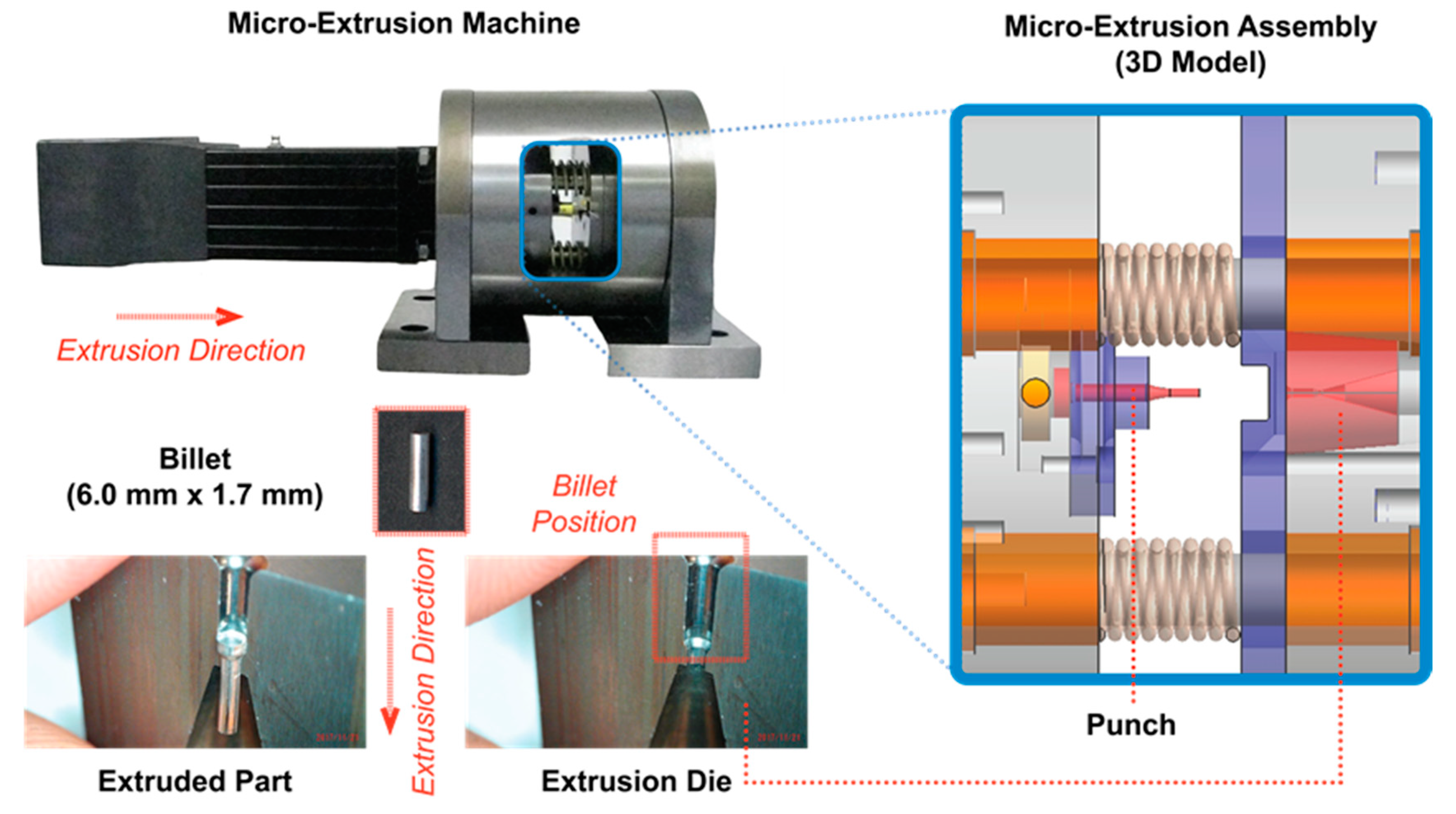
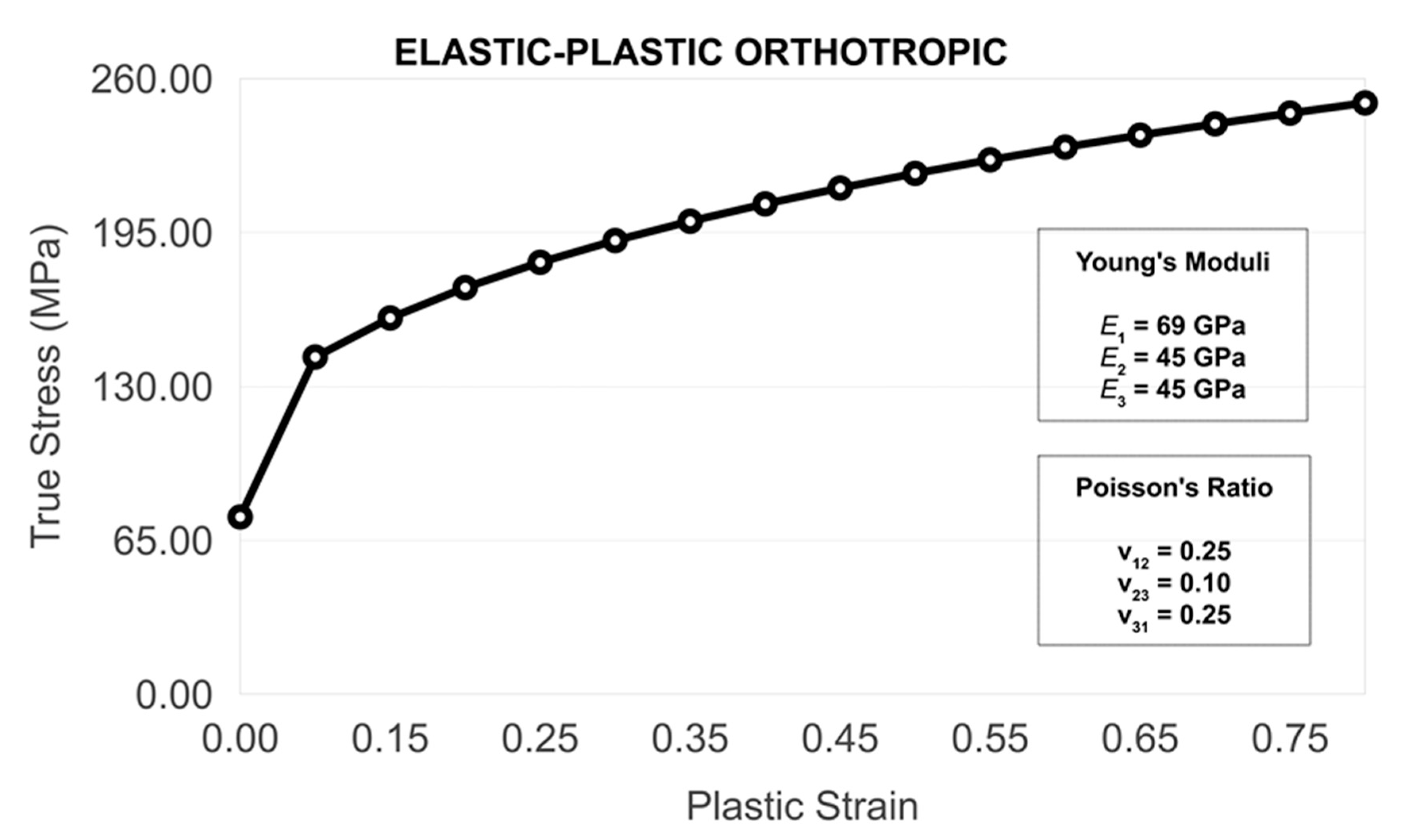
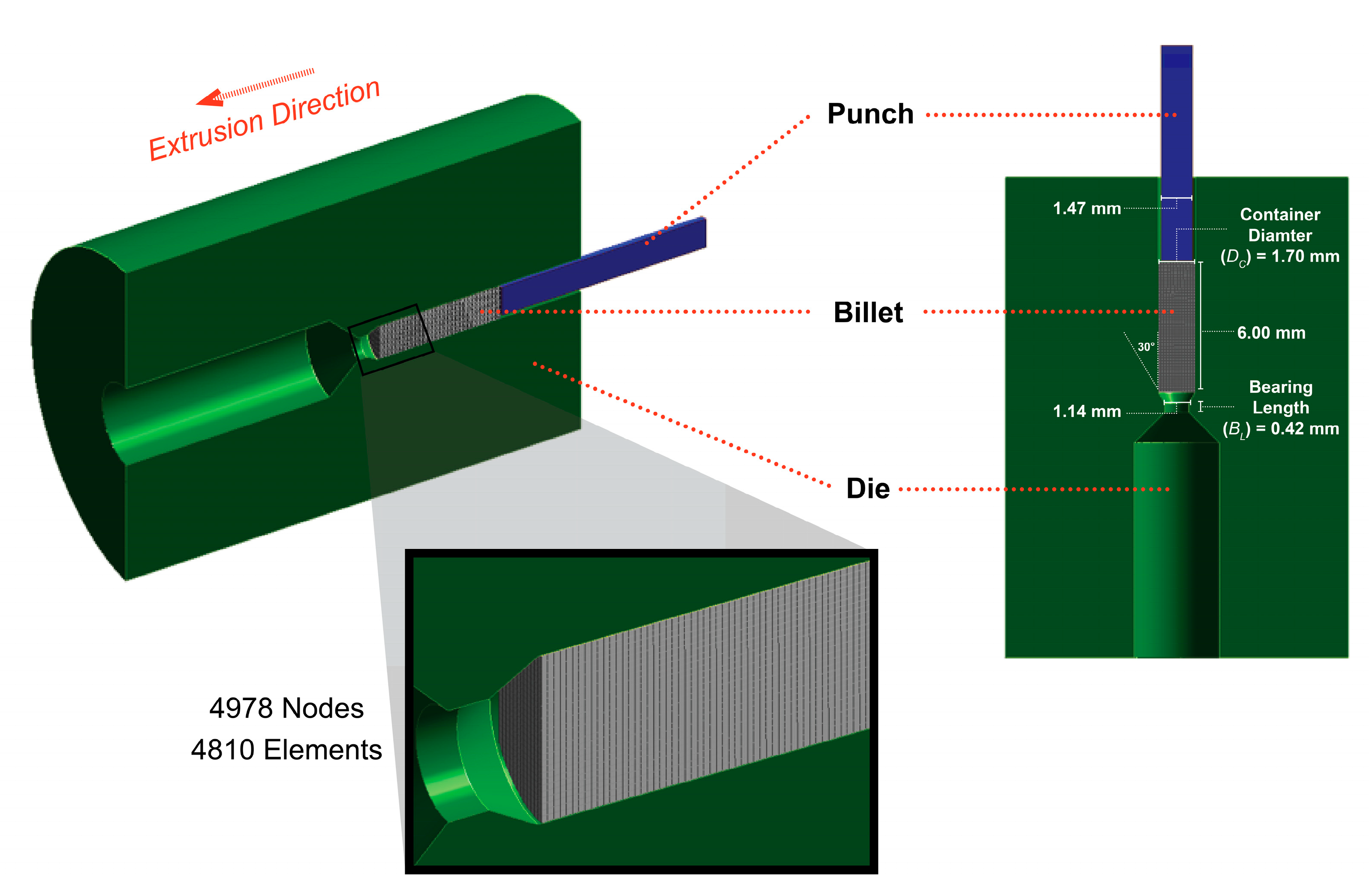
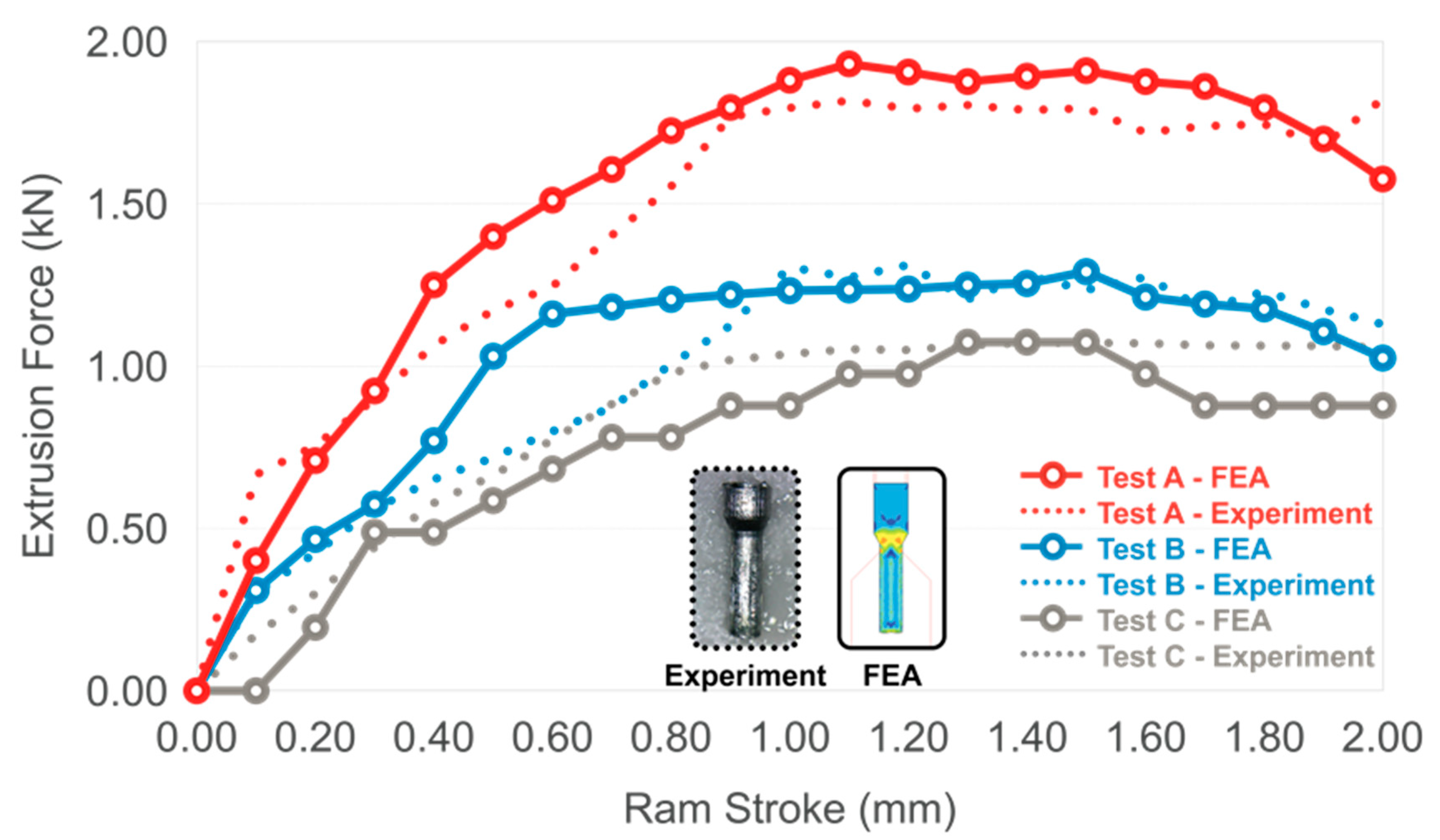
2.1. Micro-Extrusion Experiment and Simulation

The principle of the micro-extrusion process was similar to that of the traditional extrusion process but was carried out at room temperature, while also reducing the millimeter-sized billets to a few millimeter-sized or micro-sized parts. A horizontal type high-speed micro-extrusion machine (Figure 1) was used in this study to push the prepared 6.00-mm billets having a 1.70-mm diameter down to an extruded pin having a 1.14-mm diameter at room temperature. The punch and die material was SKD11. Aluminum alloy 6063 was selected as a billet material because it is a commonly used material in aluminum extrusion. The billet specimen was prepared by hot extrusion and machining, and the grain size of the non-annealed billets was 66 μm, with a hardness value of 30.7 HV. The material flow curve of the billet specimen obtained by the compression test is shown in Figure 2 (σ is stress, υ is Poisson’s ratio, E is Young’s moduli, G is shear moduli, and ε is strain).
A finite element (FE) model was developed to determine how the size effects (grain boundary and grain orientation) affected the curving behavior of the micro-extruded parts by using MSC.Marc 2019 (Lagrangian). The model was a 2D axisymmetric, four-node fully integrated element, with no heat transfer, as seen in Figure 3. A total number of 4978 nodes and 4810 elements were generated. The tools (punch and die) were set to be rigid bodies. The billet was set to be a deformable body having the power-law material model, as shown in Equation (1):
σ = k · ε n ,
where σ is the flow stress, k is the material constant, ε is the true strain, and n is the strain-hardening exponent. Since the maximum strain rate used in this work was 100 s−1 at room temperature, the effects of the strain rate on the flow stress were considered minimal, as presented in the work of Ye et al. [35]. Thus, the strain-rate sensitivity was not included in Equation (1). The flow stress-true strain curves were calculated from the cold compression tests. The material constants for aluminum alloy 6063 having a 66-μm grain size were: k = 168.40 MPa and n = 0.30. The lubricant (2.606 mm2/s kinematic viscosity) was applied at the billet-tool interfaces. The FE simulation was estimated by comparing it with the three micro-extrusion experiments, as described in Table 1.
In the validation conditions, the 66-µm grain size billet was extruded from a diameter of 1.70 mm to 1.14 mm with the 2.00-mm punch stroke. The ASTM E112 standard was used to measure the average grain size of the billet material. The main differences among these conditions were the friction conditions of the tool-billet interfaces and the extrusion speeds. The combined friction models (Coulomb and shear friction models) were used at the tool-billet interfaces, as shown in Equation (2):
f = μ s N   ( if   μ s N < τ ) , f = τ   ( if   μ s N τ ) ,
where f is friction force, µs is the static friction coefficient, N is the normal load, and τ is the shear friction force. Note that the values of the coefficient of frictions were obtained by trials and errors in the FE simulations. The results comparison between the FE simulations and experiments is illustrated in Figure 4. The considered tests (A, B, and C) had different friction pairs (different COF values). The FE results matched well with those of the experiments, implying that the material model Equation (1) and friction model Equation (2) were suitable for the micro-extrusion process.

2.2. Considered Grain Sizes, Grain Boundaries, and Grain Orientations

The initial billet textures resulted from the specimen preparation processes (hot extrusion at 460 °C, followed by annealing) for achieving the desired grain sizes (47 µm, 66 µm, and 97 µm), and their grain size distributions are illustrated in Figure 5. Three additional grain sizes were investigated, in order to look at the influences of poly-grain to single-grain conditions, as seen in Figure 6. The grain shapes used here were selected on purpose and were based on the study of Roters et al. [36]. Grain shapes with a face-centered cubic (FCC) crystal structure, clearly showing individual grains, were selected for this study. The grain sizes and shapes (boundaries) were modeled in the FE simulation based on the assumption that there were no annealing twins. The Average Grain Size (GA) was the average maximum width of each grain across the billet specimen. The Grain Size Ratio (GR) was the Average Grain Size (GA) over the billet diameter (1.70 mm). Since the material data of these set grains were not available, the prediction of the material flow curves was carried out based on the existing stress-strain curves (47 µm, 66 µm, and 97 µm) from the compression tests. The estimated material flow curves of these enlarged grains are shown in Figure 7, and their power-law model constants are described in Table 2.
The grain sizes in the simulation did not reflect typical microstructures. However, the large grain sizes and grain boundaries in this study were specifically chosen to determine their influences on the curvature and if they could be potentially produced by using the grain selector method in our parallel study (single-crystal parts manufacturing). A few examples of the grain selection method can be found in the cited papers [38,39,40,41]. Since the stress-strain curves strongly depend on the loading axis, single crystals with different orientations would yield different stress-strain curves. In this study, instead of changing the loading axis to obtain different grain orientations, the stress-strain curves were oriented in set degrees away from the loading axis. In Figure 8, the loading axis (extrusion direction) was the x-axis. Since the material model was elastic-plastic orthotropic, the orientation of the stress-strain curves could be varied by changing the orthotropic elastic principal direction (E11). If E11 of any particular grain rotated (or changed orientation), its stress-strain curve changed. The grain orientation was described by the plane angle subtended by an arc along the x-axis (radians). For instance, if E11 equals 0 radians, the grain orientation is aligned with the x-axis (extrusion direction). If E11 equals 0.79 radians, the grain orientation is rotated 45° counterclockwise from the x-axis.

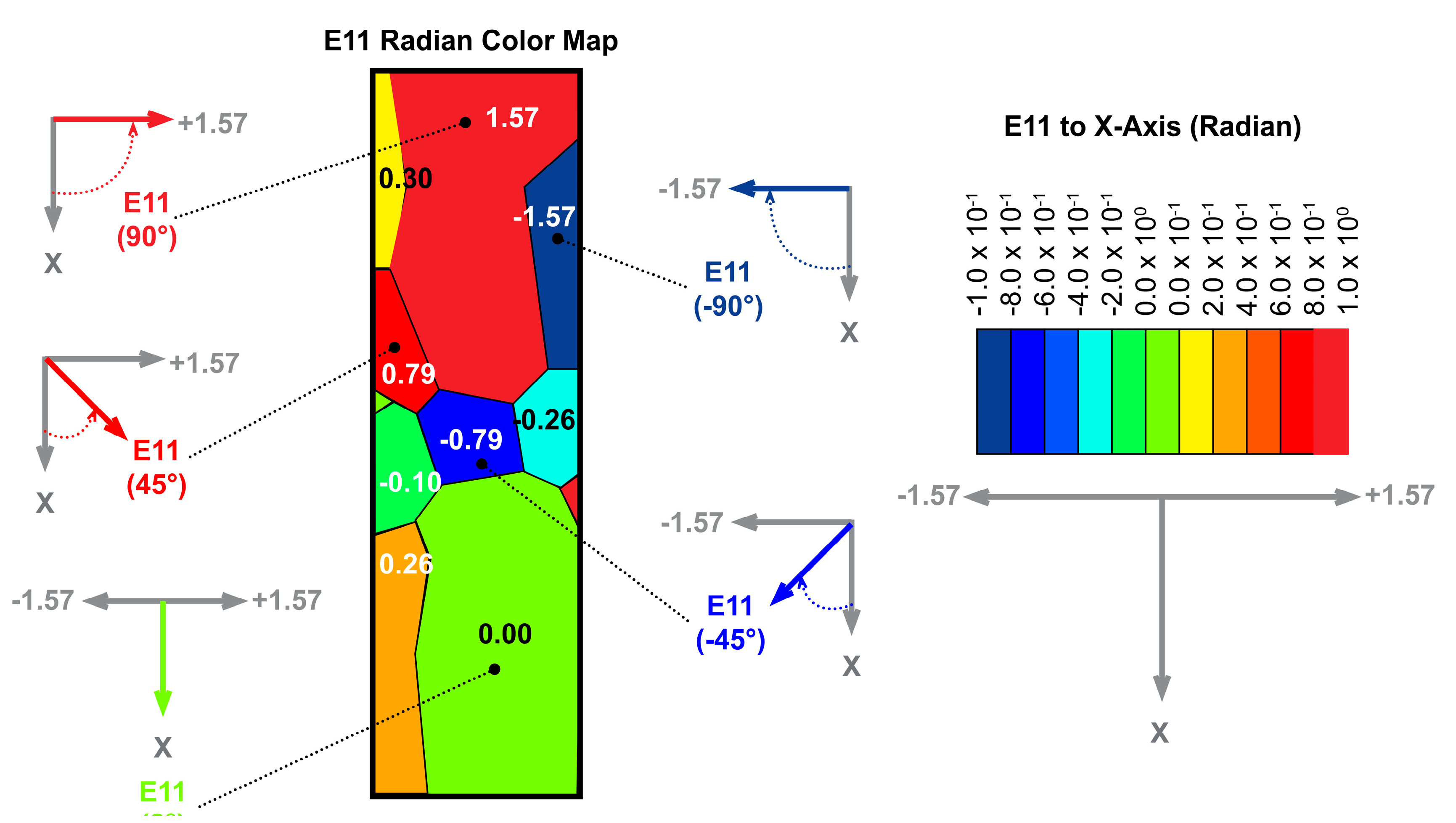
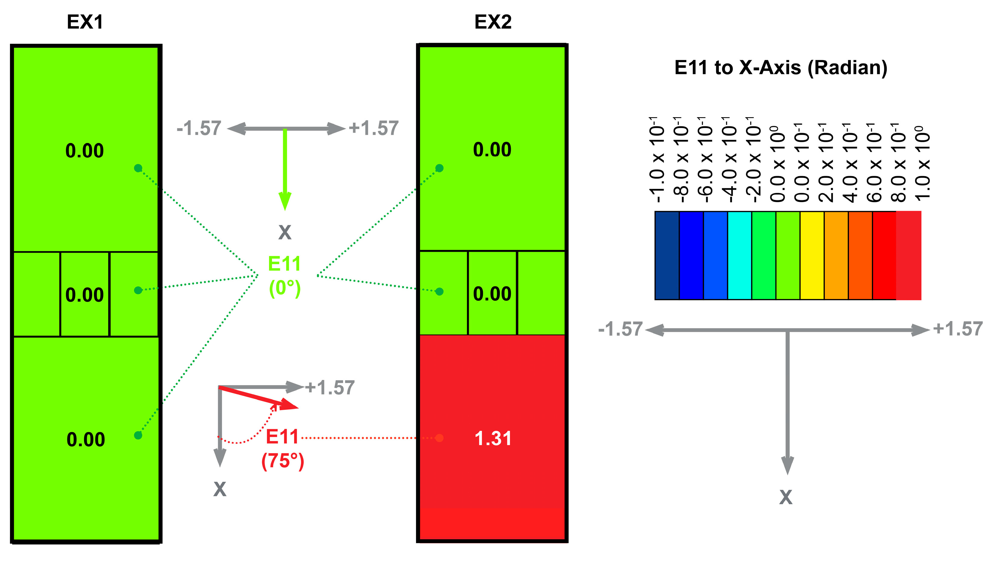
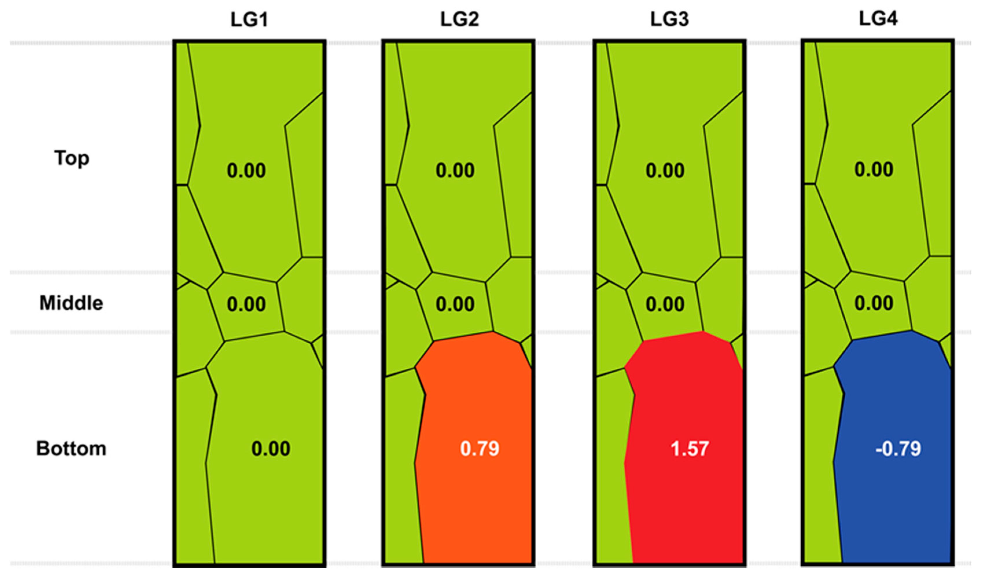
2.2.1. Grain Orientations

Two cases that had rectangular grain sizes and shapes were established in order to only investigate the grain orientation effects, as illustrated in Figure 9. In the first case (EX1), all of the grains were oriented along the x-axis (0.00 radians). For the second case (EX2), the grain sizes and boundaries were the same as those of EX1, but the only difference was the orientation of the bottom grain (E11 rotated 75° counterclockwise from the x-axis).

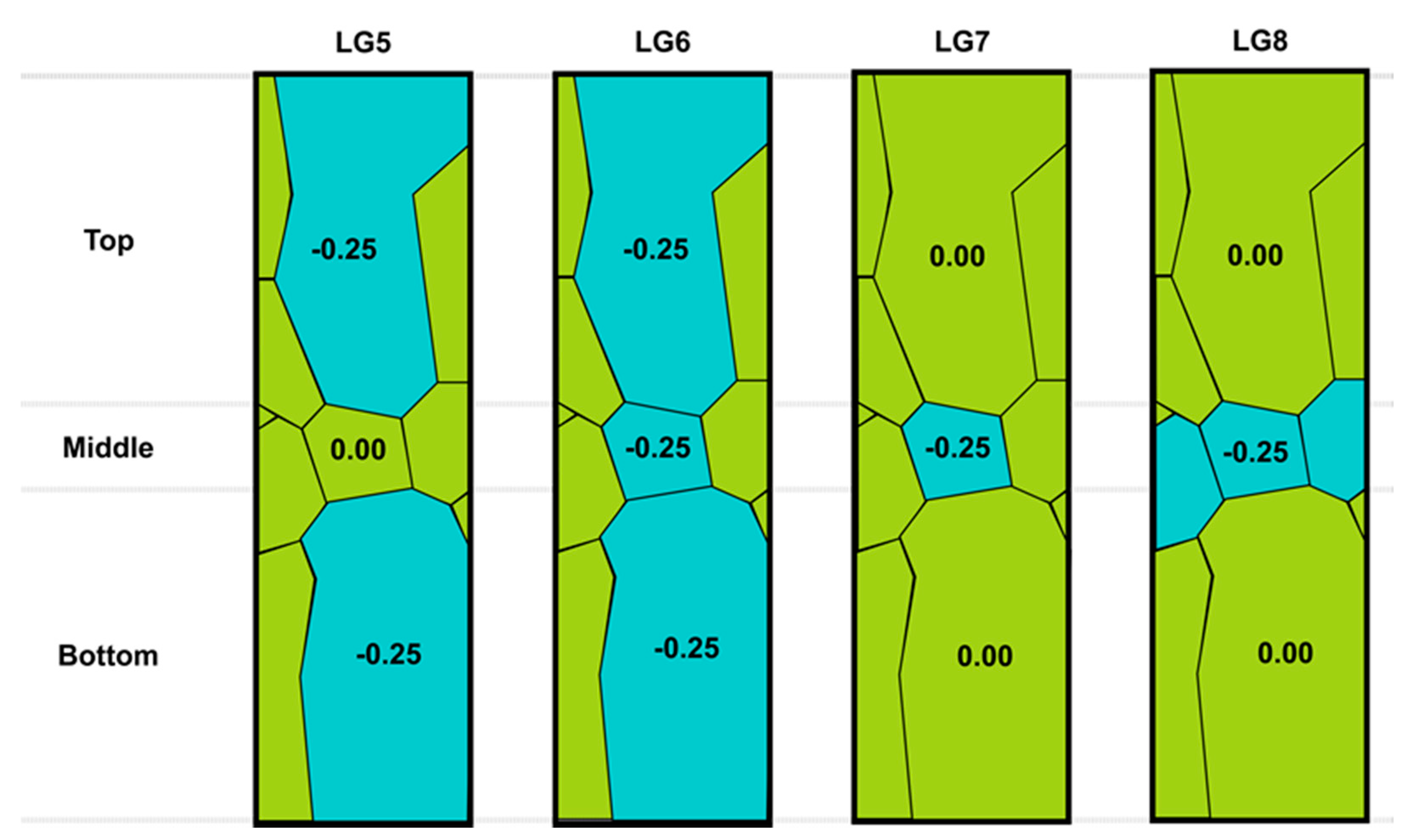
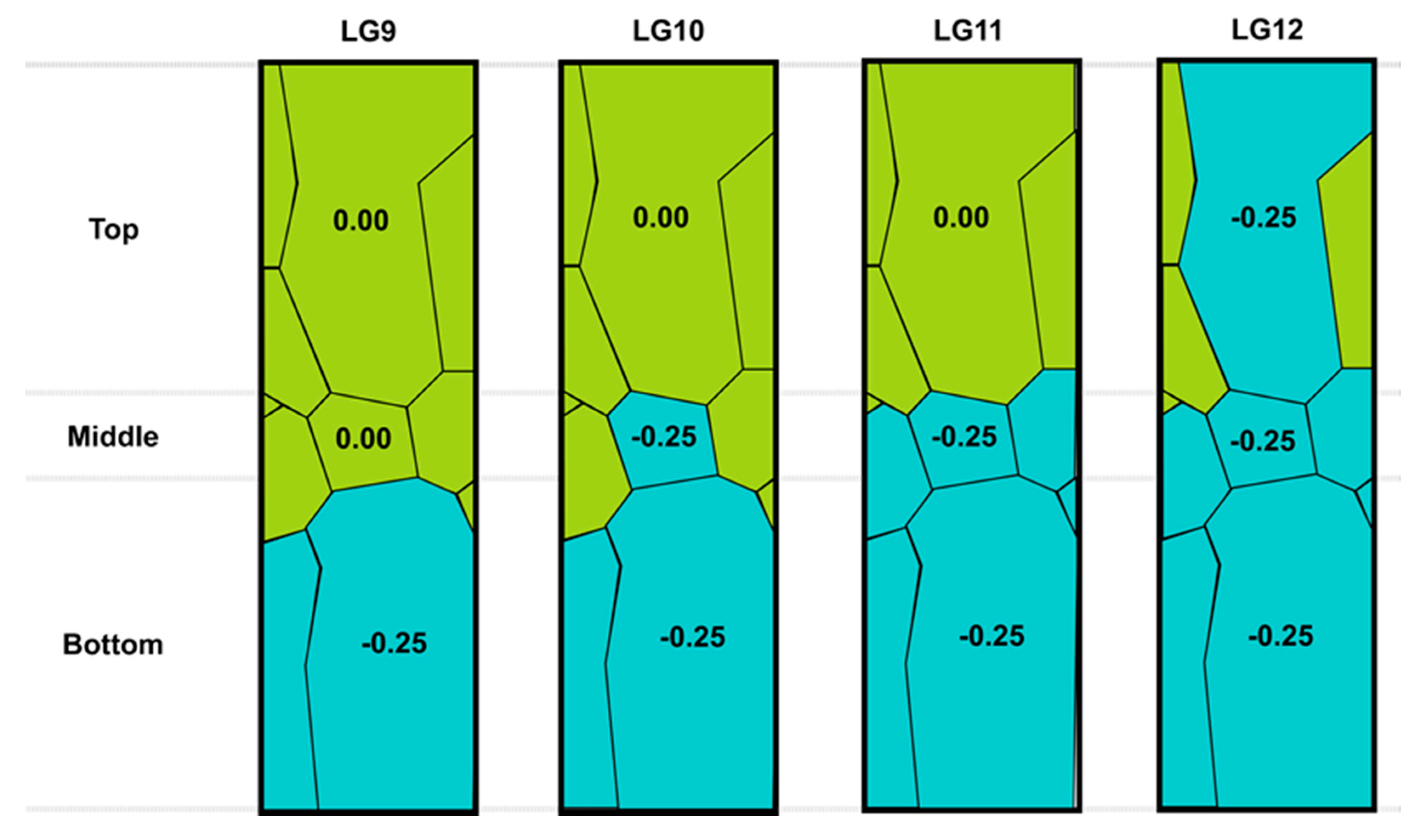
2.2.2. Grain Boundaries and Grain Orientations

In reality, those rectangular grain boundaries did not exist, so the referenced literature grain boundaries (Figure 8) were investigated throughout this study. However, the systematic way of evaluating the interactive effects of grain boundaries and grain orientations was developed as follows.
In Figure 10, all four cases (LG1 to LG4) had the same grain sizes and grain boundaries, but the only difference was the grain orientations of the bottom grains. The grain orientation was rotated 0° (LG1), 45° (LG2), 90° (LG3), and −45° (LG4) along the x-axis. In Figure 11, the influences of the top and bottom grain orientations were studied (LG5), where the grains were oriented −14.3° along the x-axis. The influences of the top, middle, and bottom grain orientations were observed in LG6. The grain orientation effects of only the middle grain (LG7) were examined. In LG8, only the middle three grains were rotated by −14.3° along the x-axis. In Figure 12, the bottom grains were turned by −14.3° along the x-axis for all four cases. The main difference was the grain orientations of the middle grain (LG10), the middle three grains (LG11), and the top and middle three grains (LG12).

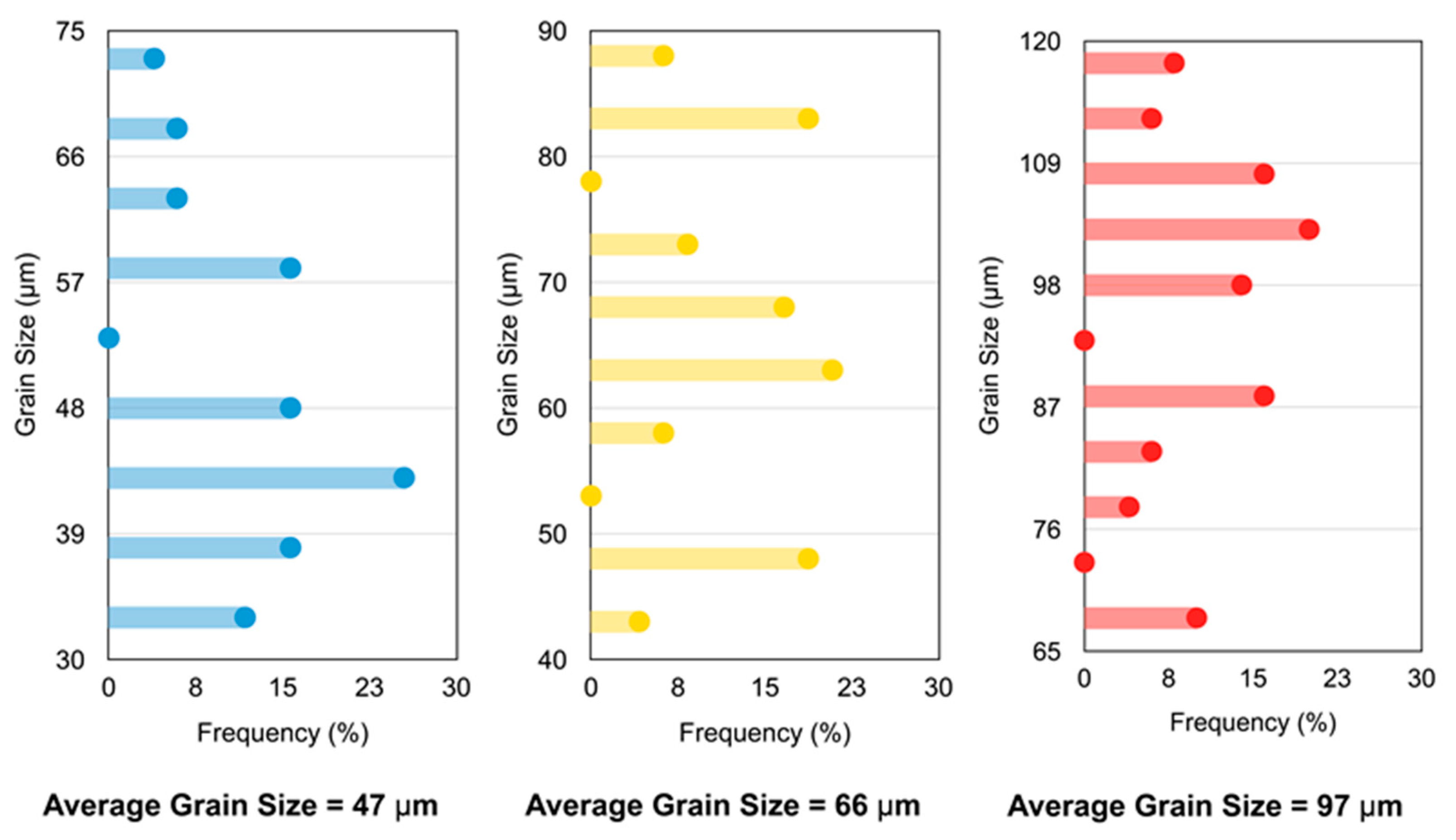
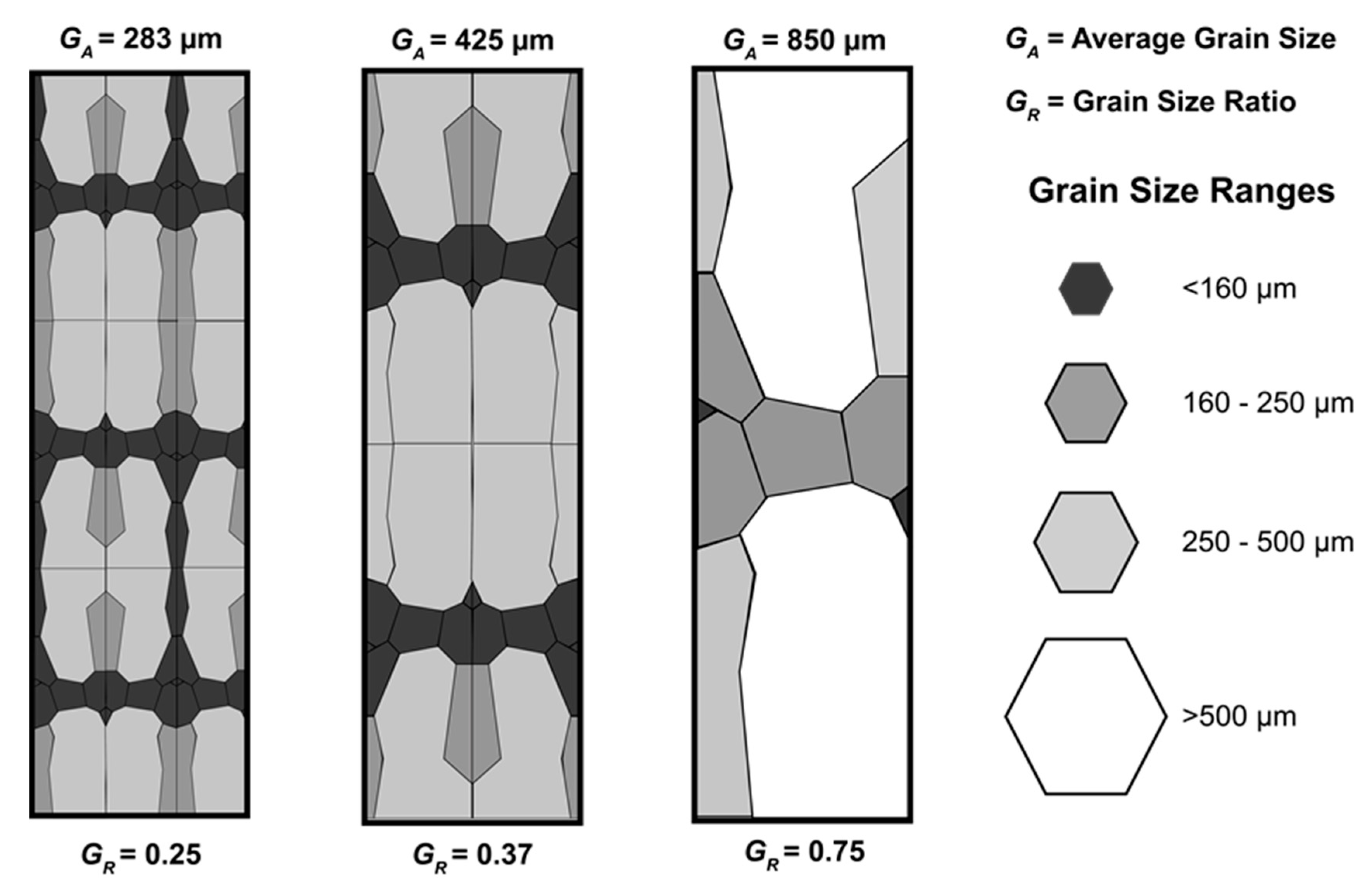
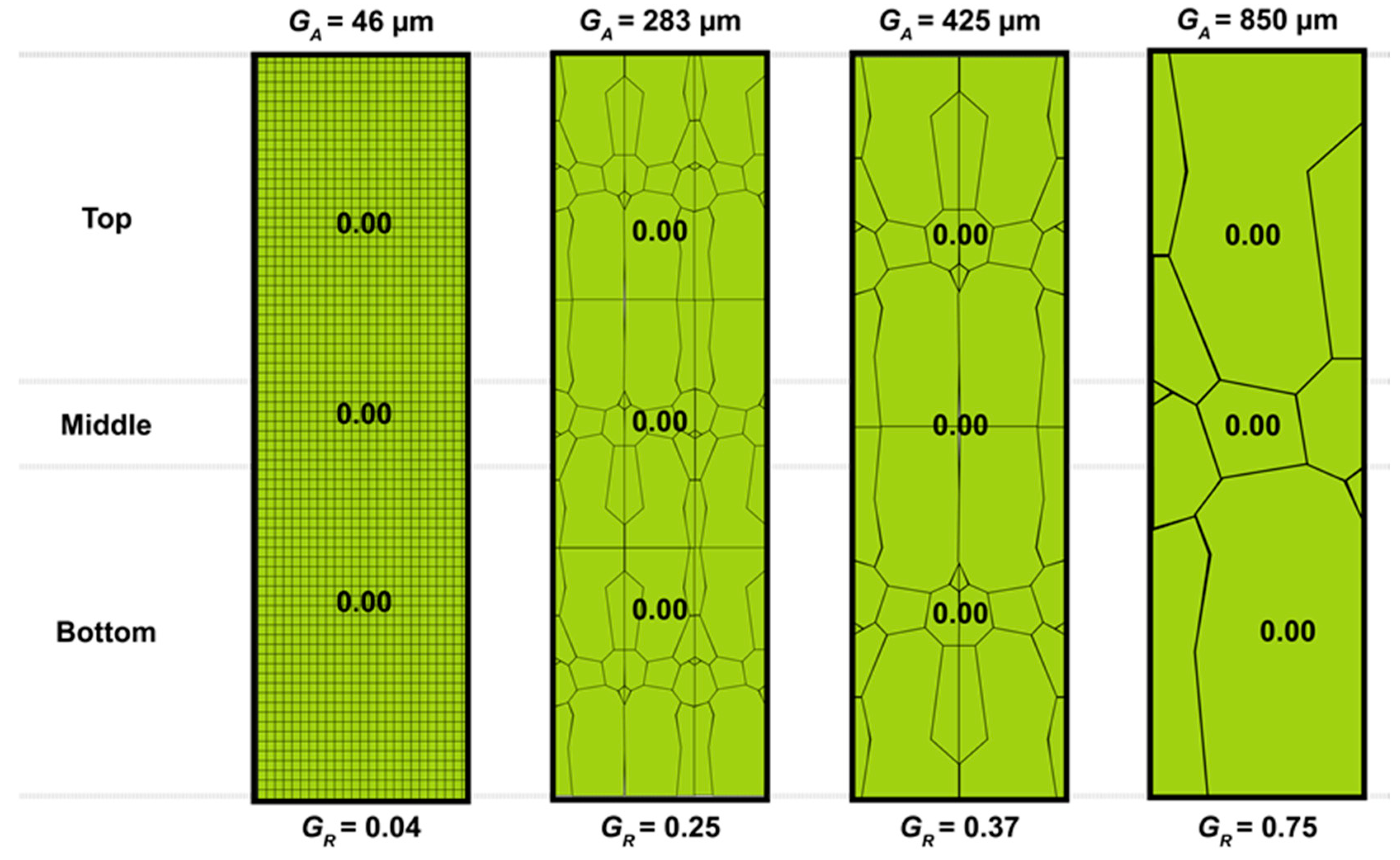
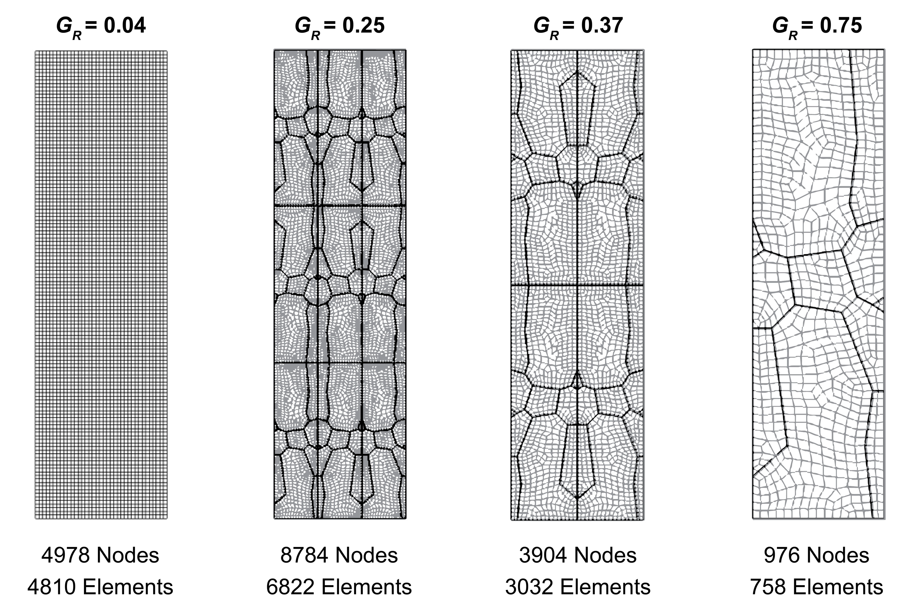
2.2.3. Grain Sizes and Grain Boundaries

The variations of the average grain sizes (GA) were established in Figure 13 to observe the coupling effects of the grain sizes and grain boundaries. Note that all four cases had the same grain orientation (0° with respect to the x-axis). Figure 14 displays the mesh elements of the enlarged grains in the finite element simulation.

2.2.4. Bearing Lengths

The effects of the bearing length (BL) were also explored in order to determine how the tool geometry affects the curvature of the micro-extruded pins. Three bearing lengths varied as follows: 0.42 mm (1X), 0.84 mm (2X), and 1.26 mm (3X).

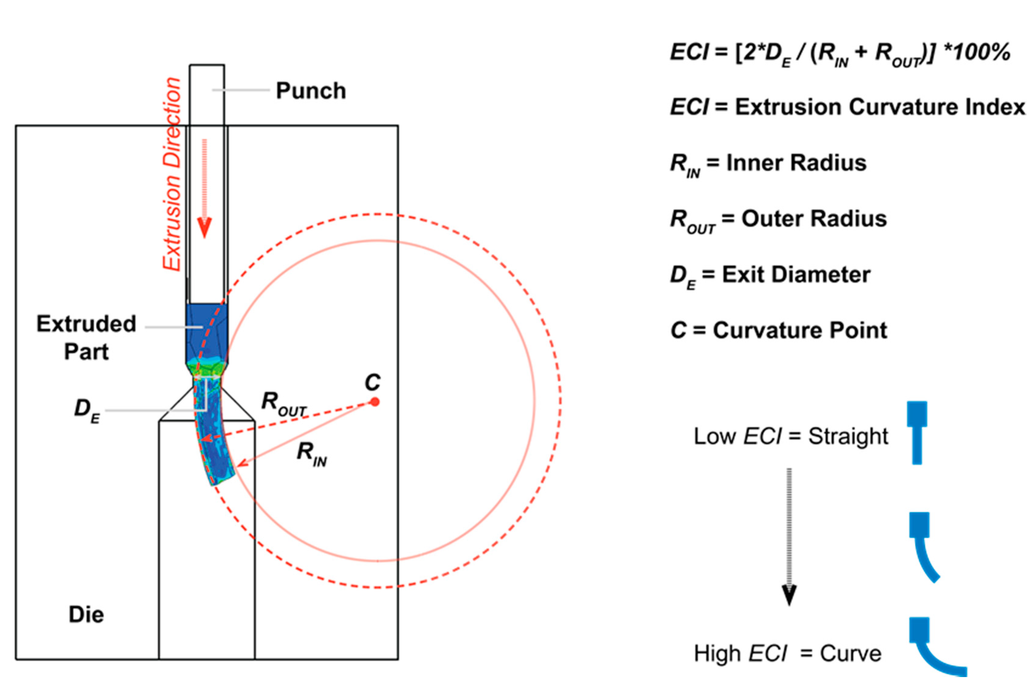
2.2.5. Extrusion Curvature Index

The Extrusion Curvature Index (ECI) was established in order to determine the amount of curvature of the micro-extruded pins, as illustrated in Figure 15. After each extrusion, the curvature point that could fit its inner radius and outer radius to the curvature of the micro-extruded pin was located. The radii were then normalized by the exit diameter (DE), and its inverse value in percentage was the Extrusion Curvature Index (ECI). High values of ECI implied a high degree of curvature. Low ECI values indicated that the micro-extruded pin was rather straight.

3. Results and Discussion

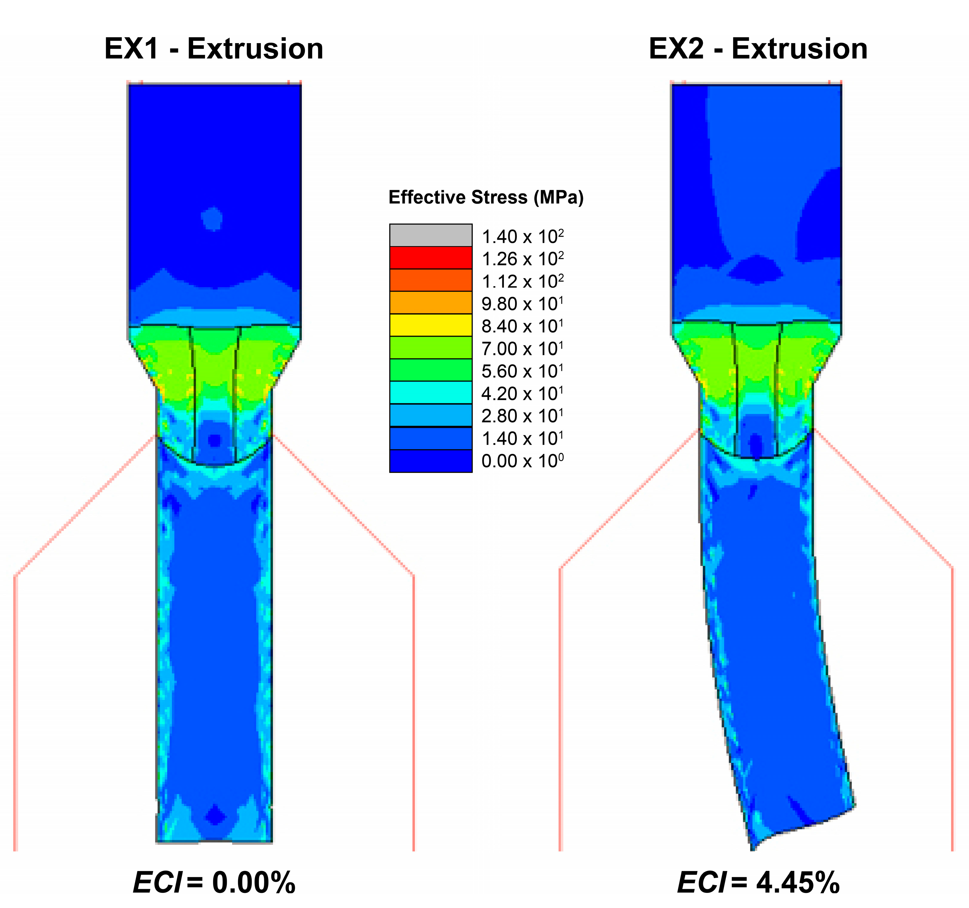
3.1. Effects of Grain Orientations

Figure 16 shows a comparison of the micro-extrusion results between the two cases (EX1 and EX2) having the same grain sizes and grain boundaries, but having different grain orientations of the bottom grains. If all grains were oriented in the same direction (EX1), and the grain sizes and grain boundaries were symmetric along the extrusion direction, there should be no curvature at all. The results of EX1 demonstrated that the FE simulation was valid. The results of EX2 clearly showed that the bottom grain orientation that was rotated 75° with respect to the x-axis caused the micro-extrusion pin to bend (ECI = 4.45%). With no effects of grain sizes and grain boundaries under single-grain conditions, the change in grain orientation could cause the micro-extrusion pin to curve. Regarding the stress distributions, high stresses occurred at high deformation zones (reduction of billet diameter to the outlet diameter). These areas caused the grains to fragment, leading to smaller grain sizes and higher stress values. The simulation results provided effective stress (συ) values based on the following equation:
σ v = 1 2 [ ( σ 1 σ 2 ) 2 + ( σ 2 σ 3 ) 2 + ( σ 1 σ 3 ) 2 ]
where σ1, σ2, and σ3 are the principal stresses.

3.2. Effects of Grain Boundaries and Grain Orientations

Figure 17, Figure 18 and Figure 19 show the FE results of the considered conditions in order to observe the influences of the grain boundaries and grain orientations when the Grain Size Ratio (GR) was 0.75.
In other words, the average number of grains across the specimen was 1.3 (single-grain) under all the conditions. In LG1, all of the grain orientations were along the x-axis, which showed that the micro-extrusion pin was curved. This result indicated that, when there was no influence from the grain orientation, the grain boundaries alone could significantly affect the curvature. It could be observed that the grain boundaries were not symmetric along the x-axis, causing the specimen to flow nonuniformly into the extrusion die. This behavior implied that the asymmetric grain boundaries were the primary driving mechanism of the bending. In LG2, the effect of the grain orientation (+45° from the x-axis) of the bottom grain was coupled with the influence of the asymmetric boundaries. The ECI values of both LG1 and LG2 were similar (same curvature); thus, the effect of grain orientation was not observed here. However, when the bottom grain orientation was rotated +90° from the x-axis (LG3), the ECI values slightly increased from 6.90% to 7.17%. As a result, the grain orientation must be dramatically changed in order to see the curvature effect. When the bottom grain orientation was rotated−45° from the x-axis (or −90° opposite to LG2), the ECI values were reduced from 6.90% to 3.09%, which helped to straighten the micro-extrusion pin. This result also confirmed that the grain orientation must be significantly changed in order to see the curvature effect. In the direction of the curvature, the curvature increased with an increase in the amount of grain orientation mismatch. However, if the orientation mismatch was in the opposite direction to the curvature, the curvature decreased according to the amount of grain orientation mismatch.
Figure 18 shows the conditions (LG5 to LG8) that take into account the effects of the grain orientations from the middle and top grains. Considering LG5 and LG6, it could be noted that both the middle and top grain orientations did not affect the curvature. Similarly, the middle grain orientations (LG7 and LG8) did not affect the curvature when compared with LG1. As a result, the bottom grain orientations significantly affect the curvature. Since the bottom grain was located at the high deformation (reduced diameter) and opening area, this implied that only the grain orientations at the high strain and opening area influenced the curvature. This phenomenon could also be observed in Figure 19, where the middle and top grain orientations did not show any effects on the curvature.
Based on the results from Figure 16, Figure 17, Figure 18 and Figure 19, it could be stated that the grain boundary of the high strain and die opening area was the dominating factor for single-grain billet conditions. Since the actual metallic grain shapes were not symmetric and the grain orientations were random, the grain boundary dominated. The combination of the grain shapes (grain boundaries), grain sizes, and grain orientations dictate the direction of the curvature. In the EX2 case, there was only one single grain at the bottom of the billet. As a result, the change of grain orientation (+75° to the extrusion direction) of the bottom grain caused the extruded pin to curve to the right. In the other single-grain cases, the curvature was mainly influenced by the initial bottom grain boundaries. As seen in the LG1 case, the extruded pin was already curved to the left, even when all the bottom grain orientations were 0° to the extrusion direction. When the grain orientations of the large bottom grains were changed in the single-grain cases, the curvature directions were still towards the left, but the amount of curvature (ECI values) changed according to the set grain orientations. The results clearly showed that the initial grain boundaries of the bottom grains significantly affected the curvature directions.

3.3. Effects of Grain Sizes and Grain Boundaries

Figure 20 shows the influences of the grain sizes and grain boundaries on the micro-extrusion, when the grain orientations did not influence any of the conditions. If the Grain Size Ratio (GR) was reduced from 0.75 to 0.37 or below, the ECI values decreased dramatically. In other words, if the specimen grains moved from 1.3 to 2.7 grains or more, the micro-extrusion pin was straightened. The impact of the grain boundaries could be clearly noticed under the single-grain condition (GR = 0.75). The influence of the grain boundaries was dramatically reduced when the number of grains increased (GR = 0.37 and below). Even though the grain orientations were not considered here, it could be stated that the effects were negligible when the number of grains was increased from 1.3 to 2.7 or more, according to the previous results. The grain boundaries that were symmetrical along the extrusion axis were GR = 0.04 and GR = 0.37. Both GR = 0.25 and GR = 0.75 had asymmetric grain boundaries along the centerline. According to Figure 20, it could be observed that the increased number of grain sizes straightened the extruded pins. The results implied that the asymmetry of grain boundaries did not have an effect on the curvature in the multi-grain cases.

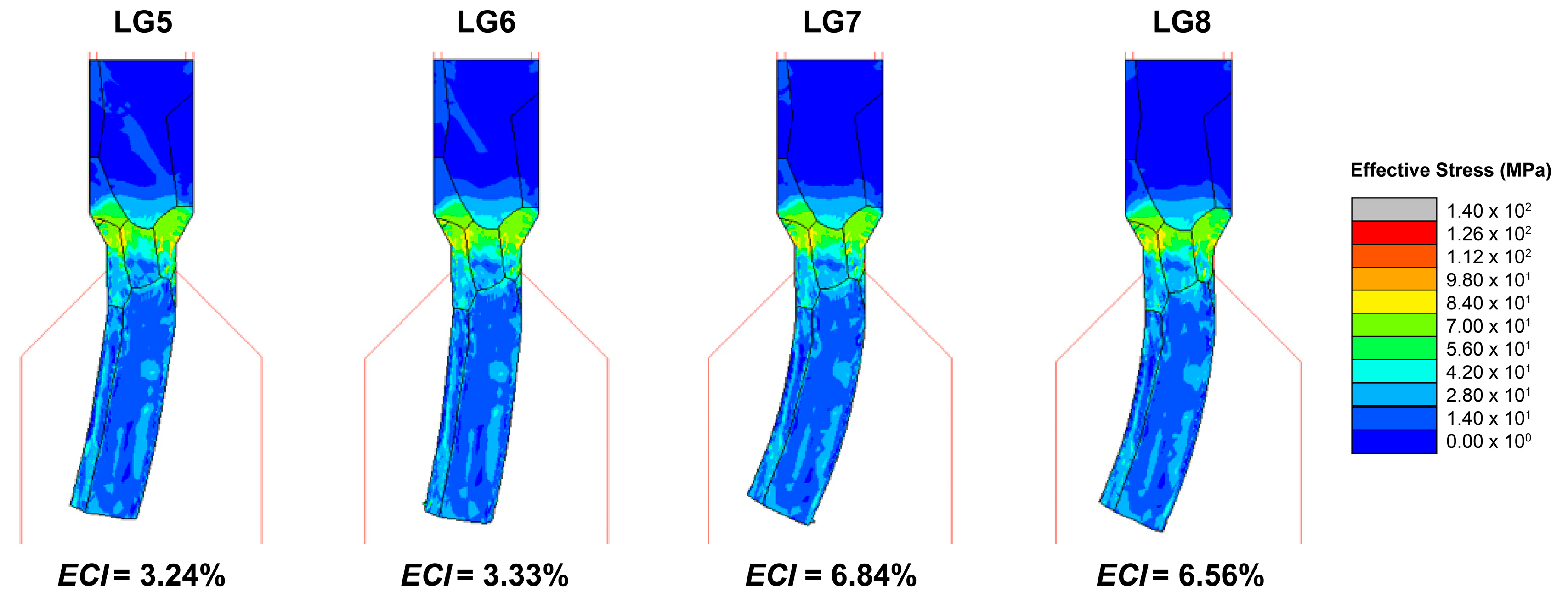
3.4. Effects of Bearing Lengths

Figure 21 shows the effects of the bearing lengths (BL) on the curvature of single-grain conditions (GR = 0.75). The ECI values decreased when the bearing lengths increased. In other words, if the bearing length was extended further, it could help strengthen the micro-extruded pins. If the BL value was increased up to 1.26 mm, which was slightly larger than the exit diameter (1.14 mm), it could almost eliminate the curvature in the micro-extrusion. As a result, the extension of the bearing lengths (BL) from the high strain and opening area could help reduce the curvature effects influenced by the grain sizes, grain boundaries, and grain orientations.
Based on the results, the following observations and analysis could be made:
-
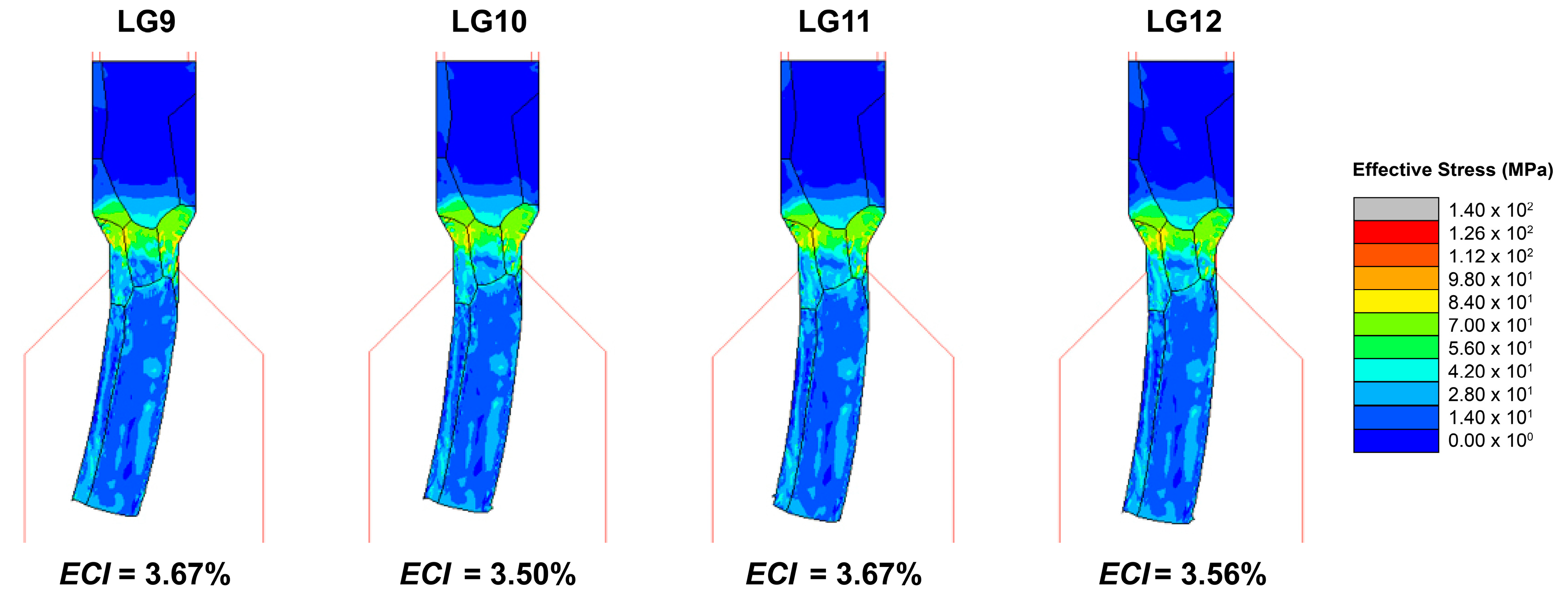
For single-grain conditions (GR = 0.75), if the grain sizes and grain boundaries were symmetric along the extrusion direction, the grain orientation was the dominating factor for the curvature. If the grain sizes and grain boundaries were not symmetric along the extrusion direction, the grain boundary at the high strain and die opening area was the dominating factor for the curvature. The interactive influences of the grain boundary and grain orientation also affected the curvature.
-
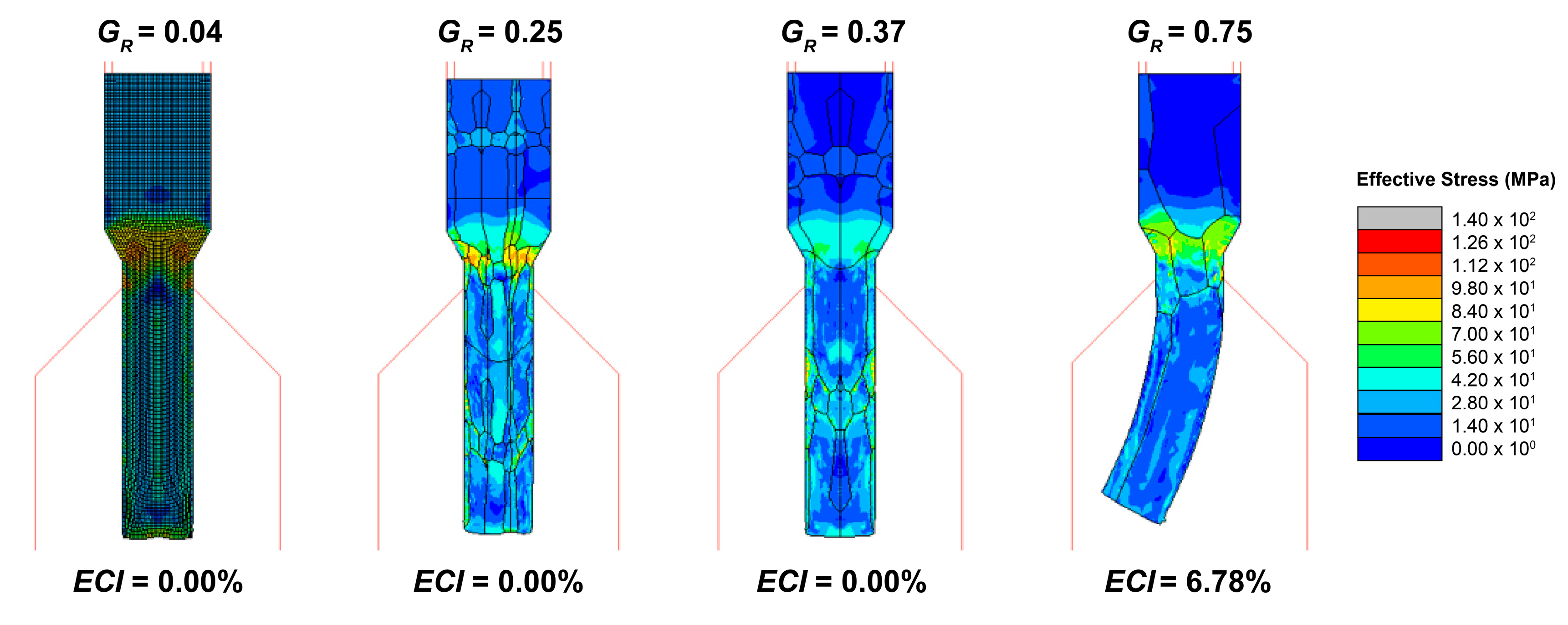
For poly-grain conditions (GR < 0.75), if the number of grains across the specimen increased up to 2.7, the curvature effects were dramatically reduced. The influences of the grain boundaries and grain orientations were not significant.
-
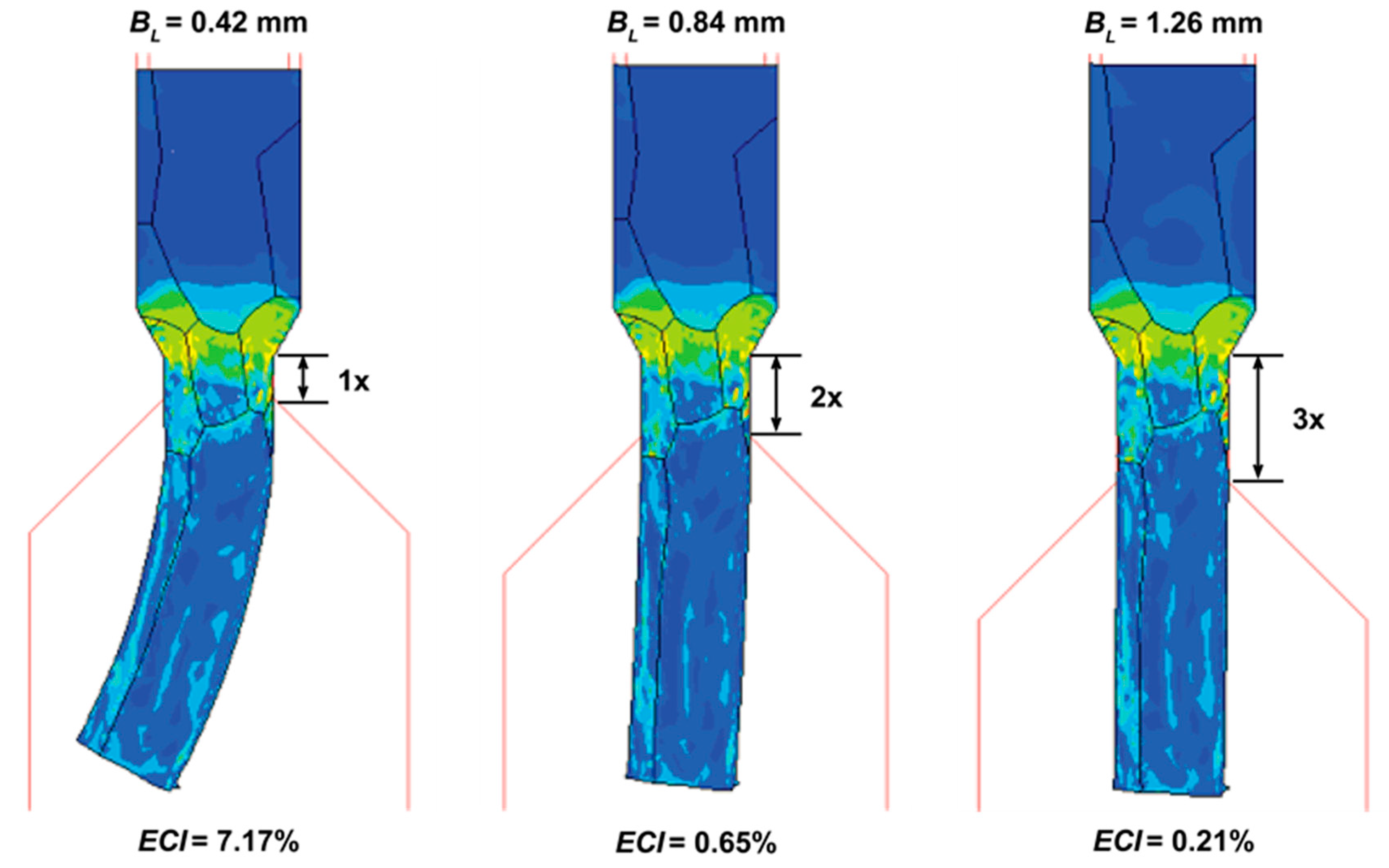
For all conditions, if the bearing lengths (BL) were extended beyond the exit diameter (DE), the micro-extrusion pins were straightened.
Although this work was carried out by using the numerical simulation method, the findings of this research work fundamentally helped explain how the micro-extrusion parts were curved. Future work within this research would apply the FE techniques to the designed grain sizes and orientations under controlled micro-extrusion process parameters. Higher-grade aluminum alloys and multi-material extrusion would also be considered by using this same technique. The results of all the studies could be integrated in order to design and develop single-crystal parts by using the grain selector. The insights gained from this series of ongoing studies could be applied to the control and optimization of lightweight multi-material micro-parts.

4. Conclusions

This research work investigated the driving mechanism behind the curvature in the micro-extrusion of a 6063 aluminum alloy at room temperature. An FE simulation was used to observe the influences of the grain sizes, grain boundaries, grain orientations, and bearing lengths. The FE simulations were validated with experiments using a 66-µm grain-size billet, and the results agreed well. The billet grain sizes were enlarged, ranging from poly-grain to single-grain conditions, and their material properties were extrapolated. The grain shapes (boundaries) were established, and the grain orientations were varied to determine the interactive effects on the curvature (Extrusion Curvature Index or ECI) of micro-extruded pins. The key finding was that the grain boundary was the dominating factor driving the mechanism of curvature in micro-extrusion under single-grain conditions.

Author Contributions

Conceptualization, N.M. and S.S.; Data curation, P.P. and N.M.; Formal analysis, P.P., N.M. and S.S.; Funding acquisition, N.M. and S.B.; Investigation, P.P. and N.M.; Methodology, P.P., N.M. and S.S.; Project administration, N.M.; Resources, N.M., T.F., N.T. and K.D.; Software, S.S.; Supervision, N.M., N.T., S.B. and K.D.; Validation, P.P. and T.F.; Visualization, N.M.; Writing—original draft, P.P.; Writing—review & editing, N.M. All authors have read and agreed to the published version of the manuscript.

Funding

This research was funded by the Thailand Research Fund (TRF), grant number MRG5980148. The APC was funded by Khon Kaen University.

Acknowledgments

The authors would like to acknowledge the supports of: LPN Metallurgical Research Center, Thailand, National Metal and Materials Technology Center (MTEC), Thailand; University of Toyama, Japan; Department of Mechanical Engineering, Northwestern University, USA; Department of Mechanical Engineering, Faculty of Engineering, Khon Kaen University; and Onward Giken Corporation, Japan.

Conflicts of Interest

The authors declare no conflict of interest.

References

  1. Cullen, J.M.; Allwood, J.M. Mapping the Global Flow of Aluminum: From Liquid Aluminum to End-Use Goods. Environ. Sci. Technol. 2013, 47, 3057–3064. [Google Scholar] [CrossRef] [PubMed] [Green Version]
  2. Alting, L.; Kimura, F.; Hansen, H.N.; Bissacco, G. Micro Engineering. CIRP Ann. 2003, 52, 635–657. [Google Scholar] [CrossRef]
  3. Dong, X.; Chen, F.; Chen, S.; Liu, Y.; Huang, Z.; Chen, H.; Feng, S.; Zhao, L.; Wu, Z.; Zhang, X. Microstructure and microhardness of hot extruded 7075 aluminum alloy micro-gear. J. Mater. Process. Technol. 2015, 219, 199–208. [Google Scholar] [CrossRef]
  4. Cowley, A.; Woodward, B. A Healthy Future: Platinum in Medical Applications. Platin. Met. Rev. 2011, 55, 98–107. [Google Scholar] [CrossRef]
  5. Geiger, M.; Kleiner, M.; Eckstein, R.; Tiesler, N.; Engel, U. Microforming. CIRP Ann. 2001, 50, 445–462. [Google Scholar] [CrossRef]
  6. Qin, Y. Micro-forming and miniature manufacturing systems—Development needs and perspectives. J. Mater. Process. Technol. 2006, 177, 8–18. [Google Scholar] [CrossRef]
  7. Gronostajski, Z.; Pater, Z.; Madej, L.; Gontarz, A.; Lisiecki, L.; Łukaszek-Sołek, A.; Łuksza, J.; Mróz, S.; Muskalski, Z.; Muzykiewicz, W.; et al. Recent development trends in metal forming. Arch. Civ. Mech. Eng. 2019, 19, 898–941. [Google Scholar] [CrossRef]
  8. Jeswiet, J.; Geiger, M.; Engel, U.; Kleiner, M.; Schikorra, M.; Duflou, J.; Neugebauer, R.; Bariani, P.; Bruschi, S. Metal forming progress since 2000. CIRP J. Manuf. Sci. Technol. 2008, 1, 2–17. [Google Scholar] [CrossRef]
  9. Parasız, S.A.; Kinsey, B.L.; Mahayatsanun, N.; Cao, J. Effect of specimen size and grain size on deformation in microextrusion. J. Manuf. Process. 2011, 13, 153–159. [Google Scholar] [CrossRef]
  10. Rosochowski, A.; Presz, W.; Olejnik, L.; Richert, M. Micro-extrusion of ultra-fine grained aluminium. Int. J. Adv. Manuf. Technol. 2007, 33, 137–146. [Google Scholar] [CrossRef]
  11. Fann, K.-J.; Chen, C.-C. Grain Size in Aluminum Alloy 6061 under Hot Ring Compression Test and after T6 Temper. Appl. Sci. 2017, 7, 372. [Google Scholar] [CrossRef]
  12. Justinger, H.; Hirt, G. Estimation of grain size and grain orientation influence in microforming processes by Taylor factor considerations. J. Mater. Process. Technol. 2009, 209, 2111–2121. [Google Scholar] [CrossRef]
  13. Hansen, N. The effect of grain size and strain on the tensile flow stress of aluminium at room temperature. Acta Metall. 1977, 25, 863–869. [Google Scholar] [CrossRef]
  14. Li, Y.; Bushby, A.J.; Dunstan, D.J. The Hall–Petch effect as a manifestation of the general size effect. Proc. R. Soc. A Math. Phys. Eng. Sci. 2016, 472, 20150890. [Google Scholar] [CrossRef]
  15. Kim, G.-Y.; Ni, J.; Koç, M. Modeling of the Size Effects on the Behavior of Metals in Microscale Deformation Processes. J. Manuf. Sci. Eng. 2006, 129, 470–476. [Google Scholar] [CrossRef]
  16. Wang, C.-J.; Guo, B.; Shan, D.-B.; Sun, L.-N. Effects of specimen size on flow stress of micro rod specimen. Trans. Nonferrous Met. Soc. China 2009, 19, s511–s515. [Google Scholar] [CrossRef]
  17. Parasiz, S.A.; Kinsey, B.; Krishnan, N.; Cao, J.; Li, M. Investigation of Deformation Size Effects During Microextrusion. J. Manuf. Sci. Eng. 2006, 129, 690–697. [Google Scholar] [CrossRef]
  18. Engel, U. Tribology in microforming. Wear 2006, 260, 265–273. [Google Scholar] [CrossRef]
  19. Krishnan, N.; Cao, J.; Dohda, K. Study of the Size Effect on Friction Conditions in Microextrusion—Part I: Microextrusion Experiments and Analysis. J. Manuf. Sci. Eng. 2006, 129, 669–676. [Google Scholar] [CrossRef]
  20. Mori, L.F.; Krishnan, N.; Cao, J.; Espinosa, H.D. Study of the Size Effects and Friction Conditions in Microextrusion—Part II: Size Effect in Dynamic Friction for Brass-Steel Pairs. J. Manuf. Sci. Eng. 2007, 129, 677–689. [Google Scholar] [CrossRef]
  21. Vollertsen, F.; Biermann, D.; Hansen, H.N.; Jawahir, I.S.; Kuzman, K. Size effects in manufacturing of metallic components. CIRP Ann. 2009, 58, 566–587. [Google Scholar] [CrossRef]
  22. Chan, W.L.; Fu, M.W.; Yang, B. Study of size effect in micro-extrusion process of pure copper. Mater. Des. 2011, 32, 3772–3782. [Google Scholar] [CrossRef]
  23. Deng, J.H.; Fu, M.W.; Chan, W.L. Size effect on material surface deformation behavior in micro-forming process. Mater. Sci. Eng. A 2011, 528, 4799–4806. [Google Scholar] [CrossRef]
  24. Lin, J.-F.; Li, F.; Zhang, J.-F. A new approach to investigate real flow stress in micro-extrusion. Trans. Nonferrous Met. Soc. China 2012, 22, s232–s238. [Google Scholar] [CrossRef]
  25. Xinyun, W.; Mao, Z.; Na, T.; Ning, L.; Lin, L.; Jianjun, L. A Forming Load Prediction Model in BMG Micro Backward Extrusion Process Considering Size Effect. Phys. Proced. 2013, 48, 146–151. [Google Scholar] [CrossRef] [Green Version]
  26. Ghassemali, E.; Tan, M.-J.; Wah, C.B.; Jarfors, A.E.W.; Lim, S.C.V. Grain size and workpiece dimension effects on material flow in an open-die micro-forging/extrusion process. Mater. Sci. Eng. A 2013, 582, 379–388. [Google Scholar] [CrossRef]
  27. Ghassemali, E.; Tan, M.-J.; Jarfors, A.E.W.; Lim, S.C.V. Optimization of axisymmetric open-die micro-forging/extrusion processes: An upper bound approach. Int. J. Mech. Sci. 2013, 71, 58–67. [Google Scholar] [CrossRef]
  28. Ghassemali, E.; Tan, M.-J.; Wah, C.B.; Lim, S.C.V.; Jarfors, A.E.W. Effect of cold-work on the Hall–Petch breakdown in copper based micro-components. Mech. Mater. 2015, 80, 124–135. [Google Scholar] [CrossRef] [Green Version]
  29. Rajenthirakumar, D.; Sridhar, R.; Abenethiri, R.; Kartik, R.; Bagri, D. Experimental investigations of grain size effects in forward microextrusion. Int. J. Adv. Manuf. Technol. 2016, 85, 2257–2264. [Google Scholar] [CrossRef]
  30. Wang, C.; Wang, C.; Xu, J.; Zhang, P.; Shan, D.; Guo, B. Interactive effect of microstructure and cavity dimension on filling behavior in micro coining of pure nickel. Sci. Rep. 2016, 6, 23895. [Google Scholar] [CrossRef] [PubMed]
  31. Zhou, W.; Lin, J.; Dean, T.A.; Wang, L. A novel application of sideways extrusion to produce curved aluminium profiles: Feasibility study. Procedia Eng. 2017, 207, 2304–2309. [Google Scholar] [CrossRef]
  32. Zhou, W.; Lin, J.; Dean, T.A.; Wang, L. Feasibility studies of a novel extrusion process for curved profiles: Experimentation and modelling. Int. J. Mach. Tools Manuf. 2018, 126, 27–43. [Google Scholar] [CrossRef] [Green Version]
  33. Zhang, B.; Dodaran, M.; Ahmed, S.; Shao, S.; Meng, W.J.; Juul, K.J.; Nielsen, K.L. Grain-size affected mechanical response and deformation behavior in microscale reverse extrusion. Materialia 2019, 6, 100272. [Google Scholar] [CrossRef]
  34. Truong, T.-T.; Hsu, Q.-C.; Tong, V.-C. Effects of Solid Die Types in Complex and Large-Scale Aluminum Profile Extrusion. Appl. Sci. 2020, 10, 263. [Google Scholar] [CrossRef] [Green Version]
  35. Ye, T.; Li, L.; Guo, P.; Xiao, G.; Chen, Z. Effect of aging treatment on the microstructure and flow behavior of 6063 aluminum alloy compressed over a wide range of strain rate. Int. J. Impact Eng. 2016, 90, 72–80. [Google Scholar] [CrossRef]
  36. Roters, F.; Eisenlohr, P.; Bieler, T.R.; Raabe, D. Crystal Plasticity Finite Element Methods: In Materials Science and Engineering; Wiley-VCH: Weinheim, Germany, 2011. [Google Scholar]
  37. Funazuka, T.; Takatsuji, N.; Dohda, K.; Aizawa, T. Effect of Grain Size on Formability in Micro-extrusion-Research on Forward-Backward Micro-extrusion of Aluminum Alloy 1st Report-. J. Jpn. Soc. Technol. Plast. 2018, 59, 8–13. [Google Scholar] [CrossRef] [Green Version]
  38. Pan, D.; Xu, Q.; Liu, B.; Li, J.; Yuan, H.; Jin, H. Modeling of grain selection during directional solidification of single crystal superalloy turbine blade castings. JOM 2010, 62, 30–34. [Google Scholar] [CrossRef]
  39. Dai, H.J.; D’Souza, N.; Dong, H.B. Grain Selection in Spiral Selectors During Investment Casting of Single-Crystal Turbine Blades: Part I. Experimental Investigation. Metall. Mater. Trans. A 2011, 42, 3430–3438. [Google Scholar] [CrossRef]
  40. Dai, H.J.; Dong, H.B.; D’Souza, N.; Gebelin, J.C.; Reed, R.C. Grain Selection in Spiral Selectors During Investment Casting of Single-Crystal Components: Part II. Numerical Modeling. Metall. Mater. Trans. A 2011, 42, 3439–3446. [Google Scholar] [CrossRef]
  41. Zhang, H.; Xu, Q. Simulation and Experimental Studies on Grain Selection and Structure Design of the Spiral Selector for Casting Single Crystal Ni-Based Superalloy. Materials 2017, 10, 1236. [Google Scholar] [CrossRef] [Green Version]
Figure 1. The micro-extrusion machine with the assembly model, and the micro-extrusion setup.
Applsci 10 04767 g001
Figure 2. The stress strain curve of the aluminum alloy 6063 having a 66-μm grain size.
Applsci 10 04767 g002
Figure 3. The finite element simulation setup of the micro-extrusion process.
Applsci 10 04767 g003
Figure 4. The results comparison between the experimental and FE micro-extrusion tests by using the 66-μm grain-size billets under different friction conditions.
Applsci 10 04767 g004
Figure 5. The grain size distributions of the 47-µm, 66-µm, and 97-µm grains.
Applsci 10 04767 g005
Figure 6. The considered grain sizes and shapes (boundaries) in this study.
Applsci 10 04767 g006
Figure 7. The estimated stress-strain curves of the considered grain sizes.
Applsci 10 04767 g007
Figure 8. The random grain orientations via rotating the orthotropic elastic principal direction (E11) along the x-axis.
Applsci 10 04767 g008
Figure 9. The two cases having the same grain sizes and shapes except for their grain orientations.
Applsci 10 04767 g009
Figure 10. The grain orientations of the four considered cases (LG1 to LG4).
Applsci 10 04767 g010
Figure 11. The grain orientations of the four considered cases (LG5 to LG8).
Applsci 10 04767 g011
Figure 12. The grain orientations of the four considered cases (LG9 to LG12).
Applsci 10 04767 g012
Figure 13. The grain boundaries of the four considered cases (small to large grain sizes) having the same grain orientation.
Applsci 10 04767 g013
Figure 14. The meshing elements and nodes of the studied grain sizes.
Applsci 10 04767 g014
Figure 15. The schematic and calculation of the Extrusion Curvature Index (ECI).
Applsci 10 04767 g015
Figure 16. The micro-extrusion results comparison between the EX1 and EX2 conditions.
Applsci 10 04767 g016
Figure 17. The micro-extrusion results of the considered conditions (LG1–LG4).
Applsci 10 04767 g017
Figure 18. The micro-extrusion results of the considered conditions (LG5–LG8).
Applsci 10 04767 g018
Figure 19. The micro-extrusion results of the considered conditions (LG9–LG12).
Applsci 10 04767 g019
Figure 20. The results comparison among different grain sizes.
Applsci 10 04767 g020
Figure 21. The results comparison among different bearing lengths.
Applsci 10 04767 g021
Table 1. Experimental validation conditions for the finite element (FE) model.
ConditionLubricationTool CoatingCoefficient of FrictionExtrusion Speed
Test APAO Lubricant (2.6 mm2/s Kinematic Viscosity)Uncoated0.450.10 mm/s
Test BPAO Lubricant (428.6 mm2/s Kinematic Viscosity)Uncoated0.250.10 mm/s
Test CDry (No Lubricant)DLC (PVD)0.11100 mm/s
Table 2. The material constants in the power-law model of the enlarged grains [37].
Average Grain SizeMaterial Constant (k)Strain Hardening Exponent (n)Source of Data [37]
47 μm265.30 MPa0.27Compression Test
66 μm168.40 MPa0.30Compression Test *
97 μm163.10 MPa0.25Compression Test
150 μm113.00 MPa0.23Prediction
200 μm94.12 MPa0.23Prediction
375 μm63.13 MPa0.21Prediction
500 μm52.58 MPa0.20Prediction
* The k and n values here were used in Equation (1) to obtain the material flow curve of the 66-μm grain size.

