Abstract
Neurological patients using a powered lower-body exoskeleton for rehabilitation of standing and walking skills in an upright body pose face the safety challenge of postural instability and fall. Current research, therefore, develops exoskeletons with self-balancing functions. This study suggests basing the exoskeleton’s stabilization of standing posture on a human-derived postural control mechanism. A corresponding control system has previously been successfully tested with specific balancing tasks in humanoid robots. Here, we provide a short introduction into the control method and, using a lightweight robot, present as a test of the balancing an experimental shift in the body weight distribution (as if, e.g., a human exoskeleton user was raising an arm or leaning the upper body or lifting an external weight). An overview of other specific balancing tests previously already investigated in humans and humanoids is also briefly mentioned. Overall, the tests will allow the quantification of the capabilities of self-balancing exoskeletons developed for patients with partial paralysis of lower body sensorimotor functions.
1. Introduction
Consider a patient with stroke or incomplete spinal cord injury (iSCI) who uses a powered exoskeleton as an assistive device for the training of residual lower body sensorimotor skills (with additional beneficial effects of bringing the body upright for blood pressure regulation and bowel functions; overview in [1,2,3]). The task of the exoskeleton here is to sense leg and hip movements and to enhance or produce the joint forces such that the patient can perform the desired movements such as hip, knee and ankle flexion and extension. With standing and on-ground walking, balancing is then typically performed using hand–arm crutches that are used in a “quadruped”-like standing and walking style, i.e., with the upper body leaning forward and supported. This is different from the normal bipedal standing and walking style originally learned and used. Furthermore, it constrains the usage of arms and hands, and it is very exhausting [4,5,6].
Physiologically, the deficits typically affect the two main constituents of sensorimotor control, i.e., the “proactive” part that provides voluntary action and the “reactive” (often reflexive) part that controls the postural stability and body balancing in response to external and self-produced disturbances (e.g., from the effects of gravity and intersegmental reaction forces; compare [4]). Current research and developments aim therefore to extend the functionality of the exoskeleton such that it provides also posture control [7,8,9,10] in addition to the control of voluntary movements. Stability, fall-safe control, and balance recovery are also a current topic in exoskeleton research [11,12,13,14,15,16].
A major aim in this research field is to provide the control torque adjustments in the ankle, knee and hip joints of the exoskeleton required for voluntary action and the standing balance (unconsidered remain here targeted foot placements as an additional constituent of maintaining walking balance). It is important that the sensorimotor control of the exoskeleton corresponds to that intended and anticipated by the patient. This concerns the sensory information on joint kinematics and kinetics and foot sole pressure as well as vestibular and visual derived estimates of the kinematics of the body COM (center of mass) and the corresponding ego-motion perception in space. With major discrepancies between expected and actual sensorimotor signals, considerable extra training would be required for the patients, and patients’ compliance may suffer. This paper, therefore, suggests using a method for the sensorimotor control of the exoskeleton that is human-derived and therefore complies by and large to human habits and expectations.
This human-derived sensorimotor controller with proactive and reactive (self-balancing) properties is described in the following in abbreviated form. It has previously already been implemented into humanoid robots for proof of principle (showing, for example, that it tolerates ‘real world’ noise and inaccuracies and copes with external and self-produced disturbances). Descriptions of this ‘disturbance estimation and compensation’ (DEC) controller, can be found in [7,15,16,17]. Here we present it in abbreviated form and test its functionality using a novel experimental paradigm.
2. Functionality of Exoskeleton
Targeted exoskeleton device. The focus of this paper is on enhancing the standing balance of the patient-exoskeleton system with external disturbances and with self-produced disturbances that may arise along with active body movements. Disturbance prediction—relevant for self-produced disturbances in humans in view of considerable feedback time delays (see [7])—as well as mechanisms specific for walking such as foot placement control, are not considered here.
Patient-exoskeleton integration. The considered exoskeleton type (Figure 1) is equipped in the body sagittal plane with hinge joint actuators at the level of the hip, knee and ankle joints. The patient is connected to it using strap fixations for pelvis (with abdomen), thighs, shanks and feet. The bilateral sets of actuators are controlled using angle and torque sensors. In the frontal plane, the exoskeleton is passively stable, so that the balancing task during stance is restricted to the sagittal body plane. The anthropomorphic structure and actuation design of the proposed exoskeleton is similar to the one of the robotic exoskeleton Exo-H3 by CSIC/Technaid [13] or the one presented in [18]. We acknowledge that this is just one of the possible solutions because, typically, exoskeletons have only hip and knee motors and no lateral DoFs [2] and some wearable robots do not have an anthropomorphic design, e.g., [19].
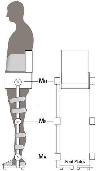
Figure 1.
Schematic representation of the suggested powered lower-body exoskeleton. MH, MK and MA, motorized actuators for hip, knee and ankle joints, respectively. The strap from back support over the abdomen reduces trunk bending in the lower vertebral column, whereas trunk bending in the hip joints is essentially unrestrained. Arms used for lifting objects, etc. not shown for simplicity. Further details in Text.
With both sensing and executing the proactive movements and the balancing, the following two requirements need to be fulfilled: (1) Fixation of some form of artificial vestibular system to the upper exoskeleton link (compare [15]); (2) Evaluation and control of the COM of both, exoskeleton and patient; (3) Relating the COM to the common base of support, given by using common footwear for patient and exoskeleton (fixing each foot of the patient to a shoe-like footplate of the exoskeleton). Four pressure sensors under the exoskeleton’s soles of each foot are assumed to allow, together with joint angle and torque sensors, an estimation of the total weight of the COM (exoskeleton and patient) and its spatial distribution on the ground. The attempts of active movement of the user are sensed to command the exoskeleton’s movements. Given that sensory perception of interlink coordination is impaired in the patients, it is up to the exoskeleton to also deal with this information along with the motor actions required for balancing and proactive movements.
Human inspired control of balancing. The notion that human balancing skills still represent the ‘golden standard’ for the balancing of humanoid robots ([20,21,22]) applies similarly to the exoskeleton in this paper. Human balancing of stance in the absence of vision relies foremost on the ‘ankle strategy’ [13]. The balancing in the ankle joints almost continuously compensates for the gravitational torque of the body COM, which arises during spontaneous, self-produced or external stimulus-evoked body sway mainly in the sagittal body plane. Upon very rapid and large perturbations, the ankle strategy may be accompanied by transient hip and knee bending that lowers the COM [23]. This hip involvement is not to be confounded with the ‘hip strategy’ [24] where humans exert rapid hip bending to generate foot–ground shear forces for balancing the body in the sagittal plane—this occurs typically when the ankle strategy tends to fail, e.g., when standing with the feet on a perpendicular narrow beam (a situation not considered here). Furthermore, unconsidered remain support maneuvers by holding with the hands, furthermore an improvement of balancing in the presence of visual orientation cues, which owes mainly to an improvement of the rather noisy vestibular information [25] and a top–down alignment, starting with head and trunk, with respect to the perceived vertical of the visual scene [26].
A humanoid robot is used in this paper to approximate the user–exoskeleton combination. We used the robot Lucy (Figure 2) for our experiment, which uses the human-derived sensorimotor control for balancing to be described below. The robot Lucy was developed as a platform to study human inspired posture control and balance. Specifically, it was previously used to test posture control in the frontal plane [25] or in both the frontal and the sagittal plane [22,26,27]. In this work, the mass distribution of the robot will be altered without updating the control parameters by means of an additional weight fixed on the pelvis (see Figure 2A). This is meant as a preliminary test of the versatility of the control system in face of forces due to the interaction with the external environment and with the user. Each degree of freedom of the robot is equipped with an encoder (joint angle ‘proprioception’) and a torque sensor. Fixed to the robot’s upper body (head–arm–trunk, HAT, segment, here a one link rigid system), a bio-inspired vestibular system [17] estimates HAT (head, arms, trunk) angular velocity and angle with respect to the gravitational vertical and head linear acceleration for use of the control in the lower back, hip, knee and ankle joints. The description of the upper body as a unique segment is a reasonable approximation for computing the CoM sway [15]. The joints are actuated by impedance-controlled actuators using electric motors. Lucy’s anthropometrics measures are given in Table 1. In the following, we first describe the human-derived sensorimotor control system, which is used in Lucy and which we suggest for future use in exoskeletons, before reporting a novel test of the control.
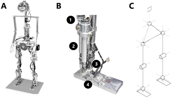
Figure 2.
Humanoid robot Lucy. (A) The humanoid. Notice the weight fixed to the pelvis; (B) detail of the actuation system in the foot: (1) DC motor, (2) spindle, (3) encoder, (4) force sensor; the same system is implemented for all the degrees of freedom; (C) schema of the 14 degrees of freedom implemented in the robot. All degrees of freedom are actuated.

Table 1.
Robot anthropometrics.
3. Human Derived Self-Balancing Control
Various self-balancing methodologies have been suggested for humanoid robots, often with reference to human balancing [19]. They lend themselves as inspiration for the self-balancing mechanism of the exoskeleton. Of particular interest is a robotics balancing methodology developed on the basis of human experiments because it may satisfy human habits and expectations. The human-derived balancing controller, described below in abbreviated form, has successfully been implemented into humanoid robots for proof of principle (showing, e.g., that it tolerates ‘real world’ noise and inaccuracies as well as external and self-produced disturbances). A detailed description of the control, called DEC (disturbance estimation and compensation) model, can be found in [7,17,28].
3.1. The Human-Derived Disturbance Estimation and Compensation (DEC) Control
Each DOF of the robotic device is equipped with a DEC module, which:
- (a)
- Provides multisensory disturbances estimates of the four basic physical joint impacts: (i) rotation and (ii) translation of supporting links as well as (iii) contact forces and (iv) field forces affecting supported links;
- (b)
- Compensates the impacts using long-latency feedback (reflex) loops in a servo control, with
- (c)
- Low loop gain that tolerates biologic feedback time delays and makes the actuation compliant and the energy consumption low.
For the cardinal body planes (here relevant only sagittal), the modules exchange disturbance information in terms of coordinate transformations, a concept originally developed on the basis of human psychophysical experiments of motion perception in [29] and later used in the DEC model [7,25]. In humans, the long latency reflexes are known to pass through the cerebral cortex, and by this can be voluntarily shaped to the behavioral demands. Such a shaping has not yet been realized for the DEC model in our computer and robot simulations. There, the network of DEC modules autonomously produces compensation of external (reflexive) and self-produced (predicted) disturbances as well as interlink coordination (see [28]).
3.2. Human-Inspired Control System in Robotic Platform
Each degree of freedom is equipped with an encoder (joint angle proprioception) and a torque sensor. Fixed to the robot’s upper body (head–arm–trunk, HAT) segment, a bio-inspired vestibular system [17] estimates HAT angular velocity and angle with respect to the gravitational vertical and linear head acceleration for use of the hip, knee and ankle joint controls (Figure 3B). The joints are actuated by impedance-controlled actuators using electric motors.
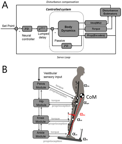
Figure 3.
(A) Schematic model of disturbance estimation and compensation (DEC) control module. The subsystem labeled “Controlled system” represents the mechanics of the body; (B) network of interconnected DEC control modules. The symbol α represents the angle in space of the upper body (αus), pelvis (αps), body center of mass (αbs), thigh (αts), shank (αss) and of the foot support base (αfs). Each module controls the CoM of all body segments above the indicated joint (example: body center of mass, CoM, above ankle joints).
The DEC control is used in a modular form here for a triple inverted pendulum (TIP) scenario, in which each module is controlling a DoF (see [30,31] for details). The four modules shown in Figure 3B are controlling the ankle joints, the knee joints and the hip joints, and the pelvis joint, respectively, while all other degrees of freedom are actuated as simulated spring dampers. In this work we implemented the compensation of support surface tilt, gravity and external torque (e.g., contact force), while the compensation of the support surface translation remained unconsidered in the experiment performed. The estimation of the disturbances to be compensated is described in the following paragraphs of this section. In general, they are based on the kinematics variables measured by the sensors (i.e., orientation of the upper body, joint angles and the respective derivatives). In order to specify the task of standing upright in terms of target position, the robot is commanded to maintain an upright stance with all the segments vertical while balancing. This is possible due to the fact that body pose is expressed in terms of segments’ sway and then there is no singularity in the control.
Support surface tilt. This tilt is estimated by combining vestibular and proprioceptive signals. The vestibular signal is implemented using the bio-inspired model presented in [15,32]. Proprioceptive signals are produced by the encoders (Figure 2B). The sensor fusion is implemented by summing the tilt and rotation velocity computed by the proprioceptive system with the joint angles provided by the proprioceptive system, as shown in (1). More details of this approach to sensor fusion are provided in [33,34,35].
The signal used to compensate the support surface rotation uses the integral of the tilt velocity of the foot in space, obtained through the down-channeling of the vestibular head in space velocity through the modules, where it is summed with the proprioceptive inputs
(hs—head–space; hp—HAT-pelvis—where HAT is Head–Arms–Trunk; pl—pelvis-leg; lsh—leg-shank; shf—shank-foot).
In this context “down-channeling” is referred to the propagation of a signal from the upper module (in this case the “pelvis module” in Figure 3B) to the lower ones (“hip”, “knee” and “ankle” modules in Figure 3B). Similarly, “up-channeling” means that the signal computed in a control module is sent to the module above (i.e., from the “ankle module” to the “knee module”). This distinction is necessary because, in the proposed bio-inspired model, the estimated foot-in-space orientation is affected by a dead-band function, see (2) and (3). The control system uses two versions of each orientation in space signal, one affected by the threshold (up-channeled from the foot) and the other one not affected by it (down-channeled from the head). The up-channeled signal is used in the servo loop, the down-channeled one is used for gravity compensation.
The foot is assumed to be always in firm contact with the support surface (as shown in Figure 3B, ). The estimated foot in space tilt is
where is the threshold function and t the current time. The term is added to make the integrator leaky (k was set to 1/80).
Given the threshold θ > 0, the function is defined as
The value of θ is a parameter of the ankle control module, in this setup it is set to 0.009 rad/s. The threshold function was introduced to mimic the nonlinear response exhibited by human subjects where larger support surface tilts are more compensated than smaller ones [7]. It can be shown that such nonlinearity does not harm the equilibrium, in that the stability of the system depends on the control parameters that are independent of the value θ [33].
The estimate of support surface tilt from (2) is up-channeled through the modules to reconstruct the orientation in space of each segment.
Gravity. The gravity torque Tg for the ankle joint is calculated by
where m is the mass of the body, h the height of the CoM, αbs its angle in space and g the gravity constant. In a similar way, the gravity disturbance acting on each joint is computed on the basis of the sway of the CoM of all the segments above the controlled joint.
Contact force disturbance. The external contact force represents the interaction with the external world, i.e., with the impact that is not produced by gravity and the movement of the support surface. The contact force disturbance estimator also identifies the unmodelled effects such as the inertial force produced by an unknown additional mass. Considering that robots and exoskeletons do not usually have a full body sensor input for contact forces, the identification of unexpected contacts with the environment should be performed on the basis of the available sensors exploiting the knowledge of the dynamics. This, for example, can be performed using a Luenberger observer with an extended state vector featuring the external force as an additional state variable [36] or, in order to cover more general nonlinear cases, a particle filter [37]. In the case of the DEC, the contact force is represented as an extra torque applied on a joint. Such a torque is computed as the difference between the applied torque (which includes the compensation of the external disturbances) and the torque computed on the basis of the kinematics. For example, the total applied torque in the ankle joint is
where J is the moment of inertia. The external torque becomes:
where Tg is the gravity torque described in the previous paragraph and Tc is the control torque produced by the module.
The same concept applies to all the joints, considering mass and moment of inertia of the set of links above the controlled joint, as explained in detail in [17].
Control equations. The disturbance compensation is implemented by summing the disturbance estimates with the input of the controller (PD in Figure 3A). For the support surface tilt, this can be seen as a coordinate transformation of the controlled variable from joint coordinates to space coordinates. Gravity and external push values are divided by mgh, resulting in an angle equivalent to the torque, i.e., the angle that would produce the torque evoked by gravity during body (or segment) lean as shown in (4). The torque commanded by the servo controller module is defined by
where Kp and Kd are the proportional and the derivative gain, respectively, and ε is the error of the controlled variable as computed using the up-channeled information. The controlled variable is specified for each module: i. Body COM sway for ankle joint, ii. Joint angle for the knee and, iii. Trunk (HAT) in space for the hip joint and the joint in the lower back. The effect of each disturbance input and of the error signal of the servo loop can be adjusted by gains (see Table 1 for module parameters) while the relation between proportional (Kp) and derivative (Kd) gain is fixed for all disturbances. Notably, all behavioral tests with Lucy—previously [17] and here—are performed with the same set of control parameters, with the aim of testing the robustness of the control system with a setup that is not accounted for by such nominal control parameters. According to (6), including Text as an input for the PD controller means that there is a positive feedback of the active torque in the joint. In general, this can make the system unstable, especially in the presence of delay. In order to avoid instability, the signal Text is low pass filtered using a Butterworth filter with cutoff frequency ωext and multiplied by a gain Gext smaller than unity. The control parameters are shown in Table 2.
Table 2.
Control parameters.
3.3. Balancing Experiment
In order to experimentally simulate a user–exoskeleton interaction scenario, we used the robot Lucy to represent the exoskeleton and challenged its disturbance compensation by sinusoidal support surface tilts of peak-to-peak 4° and 8° in the body’s sagittal plane. Such disturbance is relatively small compared to the capability of the system—for this reason, the robot is not expected to fall. The robot (Figure 2C) has 14 DoF. The control in the sagittal plane is implemented using 4 control modules (Figure 3B). The hypothetical exoskeleton, shown in Figure 1, has 3 DoF in the sagittal plane. In the scenario presented, the additional DoF in the back do not produce a relevant effect on the behavior. Figure 4A shows the body sway of all the body segments, computed on the basis of the internal sensors. All the segments are swaying together, i.e., the difference between the body segments’ orientation in space is very small and not exceeds considerably 1°. This suggests that it is legitimate to describe the kinematics of the body in this scenario with the sway of the body CoM (Figure 5).
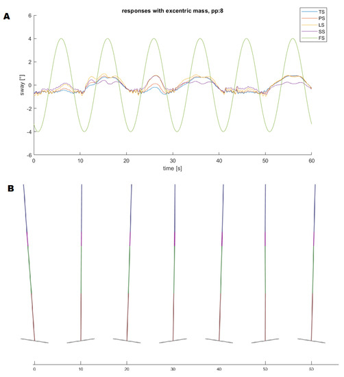
Figure 4.
(A) body sway in space of the body segments in the sagittal plane computed using the internal sensors in the presence of a peak-to-peak 8° tilt and with the addition of an eccentric weight to the pelvis (compare Figure 2A). TS—trunk-in-space; PS—pelvis-in-space; LS—leg-in-space; SS—shank-in-space; FS—foot in space. All body segments move together in this scenario, and all sways are within a range smaller than 1°; (B) stick figure showing the position of the segments at different times (every 10 s).
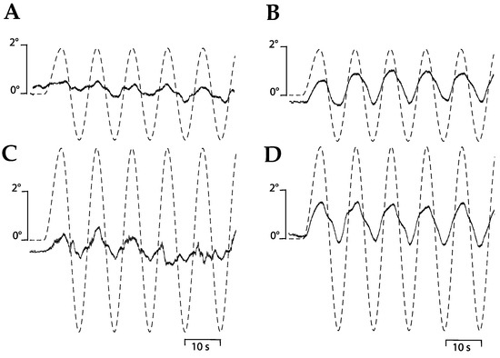
Figure 5.
Robot balancing tests. Robot Lucy successfully balanced in the body sagittal plane when presented with support surface tilts in the body sagittal plane of peak-to-peak (A) 4° and (C) 8°. Body COM sway with the addition of an eccentric weight fixed to the robot’s anterior pelvis (see Figure 2A). This increased the sway responses to the peak-to-peak (B) 4° and (D) 8° support surface tilts, but the (B and D) tilt disturbance was still well compensated. The effect owes to the ‘contact force compensation’ of the robot’s disturbance estimation and compensation (DEC) system. Balance was lost when this DEC mechanism was inactivated (not shown). This experiment mimics a situation where the exoskeleton user, while exposed to support surface tilts, would change the body weight distribution by raising the arms, leaning the upper body or lifting with a hand an external weight.
As already shown in the classical work of Horak and Nashner [24], the here implemented ‘ankle strategy’ turns the body into an inverted pendulum. Its COM is maintained close to the upright using primarily ankle torque. For example, during an evoked forward sway, muscles on the backside of the body are activated in a bottom–up way (separated by a few milliseconds) in the wake of maintaining the body segments aligned and upright. A backward sway evokes the same response pattern on the front side of the body. A different balance strategy, also described by Horak and Nashner [24] is the ‘hip strategy’, which is seen for example when humans are standing on a narrow beam. As mentioned above (Section 2), balance is then maintained by rapid hip flexion/extension, creating horizontal shear forces on the body support—a method that is restricted in its usefulness and under normal standing conditions would be more exhausting and less efficient. A modified version of the ankle strategy is seen with large perturbations where the ankle joint torques tend to exceed its limit. Human subjects then tend to bend transiently the knees to get into a squat position [23]. Conceivably, use of the ankle strategy is restricted to lower body exoskeletons with actuated ankle joints, as for example in the exoskeleton Robot [14]. It remains to be stated that the above described balancing method, which is drawing to a large extent on the ankle torque responses, is not applicable to those lower body exoskeletons which do not contain an ankle joint with actuation. The ankle strategy displayed in Figure 4B for Lucy applies not only to responses to sinusoidal support surface rotations, but also to translation and other perturbation such a push against the body. An illustrative example for responses to sinusoidal tilts and for pseudorandom translations is shown in the two films, provided in the Supplementary Material, where Lucy balances in the body sagittal plane.
Movements in the frontal plane, where no stimulus was provided, were negligible. Exoskeleton user action such as lifting an external weight, leaning the trunk or raising the arms was mimicked by producing a change in the robot’s weight distribution. To this end, an eccentric weight was fixed in front of the pelvis of the robot Lucy (see Figure 2A; 1 kg at a 12.5 cm eccentricity with respect to the body axis). It remained unaccounted in the robot’s control parameters but was drawing on the so-called contact force compensation of the DEC control (in addition to the running support surface tilt compensation). The result of the experiment was that the tilt evoked sway responses were enlarged, but balance was maintained (Figure 5B,D). When contact force compensation was disabled, in contrast, Lucy tended to fall forward during the tilt stimuli.
The robot Lucy balances during stance despite the rather weak strength of the leg actuators, DC Maxon RE-max 29 motor, providing 24 W of power. The motor has a nominal torque of 27 mNm. A linear drive is implemented with a screw/spindle system (pitch 2 mm, estimated efficiency 90%). The lever arm is 5 cm, the resulting nominal torque in the joint is 3.8 Nm. A detail of the actuation system is shown in Figure 2B. This point is meant here to underline that the human body anthropometrics (biomechanics) support biped standing and its balancing as long as the body is kept upright. In the exoskeleton, bringing the patients from the sitting to the standing pose would require extra solutions (e.g., special equipment such as a walking cane) when one wants to unburden the exoskeleton from being equipped with strong and heavy actuators.
4. Potential Extensions of the Balancing Tests
For the sake of completeness, we point out that the contact force compensation of the DEC control can also be tested in isolation by applying a body push (Figure 6B), and that further tests may consist of support translation (Figure 6C) and the so-called “body sway referenced platform” (Figure 6D). The latter excludes feedback from ankle proprioception so that the balancing relies primarily on vestibular information (standing in a compliant surface would be a simple surrogate). These tests suggested here for the self-balancing of the exoskeleton are derived from human experiments and have been considered in detail before in [22] for robotic applications such as balancing benchmarking, together with various stimulus waveforms, e.g., sine waves or a more complex waveform that allows extraction of frequency response functions. These tests have been applied to humans, which facilitates estimation of human-likeness in the performance of the robotic application. Interestingly, when comparing in [22] humanoids of vastly different body weights (67 kg vs. 17.5 kg) the differences in overall weight had little relevance for the balancing response.
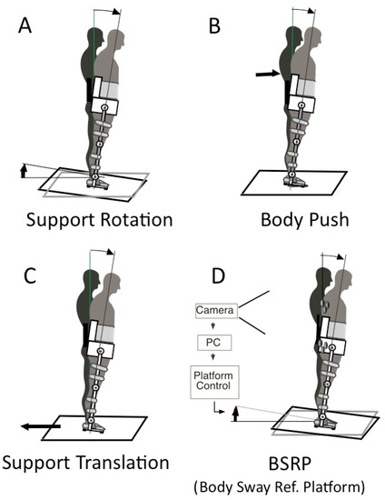
Figure 6.
(A–D) Suggested four basic tests of self-balancing of the exoskeleton (resorting directly to testing of human postural control and its application in humanoid robots; compare [12]).
5. Discussion and Conclusions
Confidence in successful control of stance stabilization is crucial for physical training with an exoskeleton. In fact, fear of falling (FOF) is often a major problem for iSCI patients, especially of those in whom fall was the reason for the spinal cord injury. In addition, FOF adversely affects the efficiency of therapy, rehabilitation and use of assistive devices [37]. Given this background, it may be advantageous if patients learn and experience that they are using a human-inspired sensorimotor control system that is performing as they expect it, and this with compliant impedance-controlled actuators that are considered safer and more comfortable for physical human–robot interaction [38].
FOF may arise if the patients experience the movements and postural actions produced by the exoskeleton as inadequate. It may be dangerous if they then try to enforce counteractions. We conceive that this may end in a dangerous “user–device conflict”. For example, fear of falling backward may lead the patient to command an inadequate forward COM lean of the user–exoskeleton body, which the exoskeleton in turn then may try to correct by a lean backward, which in turn, likely enhances the fear and action of the patient even more—a potentially disastrous positive feedback situation.
Currently, little is known about such user–device problems. We conceive that such problems can best be overcome by training and cautiously building up confidence, for example in that the patient is initially using stationary handrails when maintaining balance. The training may then include self-produced changes in the balancing situation, for example when raising the arms or lifting an object with a hand (compare above, Section 3.3, Balancing Experiment).
The control model described in the previous sections relies on the presence of a vestibular system (e.g., derived from using IMUs; [17]). This is not an obvious design choice as most of the effort in exoskeleton designs is devoted to the tracking of user’s movements (e.g., by means of encoders [39]) or muscle activity [40] or of the forces that the user applies to the robot [41] without focusing on the position of the exoskeleton itself in space. The compensation of external disturbances can coexist with the previously mentioned approaches that can be applied to the control of active movements, for example the servo loop can be controlled with a signal based on force sensors and at the same time the forces produced by the user can be explicitly considered in (6) so that they do not interfere with the compensation of the external forces. Overall, the development of robotic exoskeletons appears to be still long-lasting in view of the many difficulties to make these devices suitable for patients’ reengagement in everyday activities [42]. The integration of posture control seems one of the possible ways to improve the usability of the exoskeletons and also to inspire design decisions, e.g., in choosing the sensors.
Supplementary Materials
The following are available online at https://www.mdpi.com/2076-3417/10/15/5240/s1, Video S1: Lucy_tilt_Balancing.MP4, Video S2: Lucy_Trans_Balancing.m4v.
Author Contributions
V.L. and T.M. were responsible for study design, data collection, analysis and manuscript writing. All authors have read and agreed to the published version of the manuscript.
Funding
We acknowledge support by the German Research Foundation and the Open Access Publication Fund of TU Berlin.
Conflicts of Interest
The authors declare no conflict of interests.
References
- Chang, S.-H.; Afzal, T.; Berliner, J.; Francisco, G.E.; Kern, M.; TIRR SCI Clinical Exoskeleton Group. Exoskeleton-assisted gait training to improve gait in individuals with spinal cord injury: a pilot randomized study. Pilot Feasibility Stud. 2018, 4, 1–10. [Google Scholar] [CrossRef] [PubMed]
- Yan, T.; Cempini, M.; Oddo, C.M.; Vitiello, N. Review of assistive strategies in powered lower-limb orthoses and exoskeletons. Robot. Auton. Syst. 2015, 64, 120–136. [Google Scholar] [CrossRef]
- Lajeunesse, V.; Vincent, C.; Routhier, F.; Careau, E.; Michaud, F. Exoskeletons’ design and usefulness evidence according to a systematic review of lower limb exoskeletons used for functional mobility by people with spinal cord injury. Disabil. Rehabilitation: Assist. Technol. 2015, 11, 535–547. [Google Scholar] [CrossRef] [PubMed]
- Lal, S. Premature degenerative shoulder changes in spinal cord injury patients. Spinal Cord 1998, 36, 186–189. [Google Scholar] [CrossRef]
- Louie, D.R.; Eng, J.J.; Lam, T. Spinal Cord Injury Research Evidence (SCIRE) Research Team Gait speed using powered robotic exoskeletons after spinal cord injury: a systematic review and correlational study. J. Neuroeng. Rehabilitation 2015, 12, 82. [Google Scholar] [CrossRef]
- Talaty, M.; Esquenazi, A.; Briceno, J.E. Differentiating ability in users of the ReWalkTM powered exoskeleton: An analysis of walking kinematics. In Proceedings of the 2013 IEEE International Conference on Rehabilitation Robotics (ICORR), Seattle, WA, USA, 20–24 June 2013; pp. 1–5. [Google Scholar] [CrossRef]
- Mergner, T. A neurological view on reactive human stance control. Annu. Rev. Control. 2010, 34, 177–198. [Google Scholar] [CrossRef]
- Rajasekaran, V.; Aranda, J.; Casals, A.; Pons, J.L.; Aranda-Lopez, J. An adaptive control strategy for postural stability using a wearable robot. Robot. Auton. Syst. 2015, 73, 16–23. [Google Scholar] [CrossRef]
- Emmens, A.R.; Van Asseldonk, E.H.F.; Van Der Kooij, H. Effects of a powered ankle-foot orthosis on perturbed standing balance. J. Neuroeng. Rehabilitation 2018, 15, 50. [Google Scholar] [CrossRef]
- Emmens, A.; Van Asseldonk, E.; Masciullo, M.; Aquila, M.; Pisotta, I.; Tagliamonte, N.L.; Tamburella, F.; Molinari, M.; Van Der Kooij, H. Improving the Standing Balance of Paraplegics through the Use of a Wearable Exoskeleton. In Proceedings of the 2018 7th IEEE International Conference on Biomedical Robotics and Biomechatronics (Biorob), Enschede, The Netherlands, 26–29 August 2018; pp. 707–712. [Google Scholar] [CrossRef]
- Khalili, M.; Machiel Van der Loos, H.; Borisoff, J. Studies on Practical Applications of Safe-Fall Control Strategies for Lower Limb Exoskeletons. In Proceedings of the 2019 IEEE 16th International Conference on Rehabilitation Robotics (ICORR), Toronto, ON, Canada, 24–28 June 2019; pp. 536–541. [Google Scholar] [CrossRef]
- Tokur, D.; Grimmer, M.; Seyfarth, A. Review of balance recovery in response to external perturbations during daily activities. Hum. Mov. Sci. 2019, 69, 102546. [Google Scholar] [CrossRef]
- Robotic Exoskeleton Exo-H3|Technaid—Leading Motion. Available online: https://www.technaid.com/products/robotic-exoskeleton-exo-exoesqueleto-h3/ (accessed on 6 July 2020).
- Hyon, S.; Morimoto, J.; Matsubara, T.; Noda, T.; Kawato, M. XoR: Hybrid drive exoskeleton robot that can balance. In Proceedings of the 2011 IEEE/RSJ International Conference on Intelligent Robots and Systems, San Francisco, CA, USA, 25–30 September 2011; 2011; pp. 3975–3981. [Google Scholar]
- Chang, M.; Kim, Y.; Lee, Y.; Jeon, D. A research on the postural stability of a person wearing the lower limb exoskeletal robot by the HAT model. In Proceedings of the 2017 International Conference on Rehabilitation Robotics (ICORR), London, UK, 17–20 July 2017. [Google Scholar] [CrossRef]
- Khalili, M.; Borisoff, J.; Van der Loos, H. Developing safe fall strategies for lower limb exoskeletons. In Proceedings of the 2017 International Conference on Rehabilitation Robotics (ICORR), London, UK, 17–20 July 2017; pp. 314–319. [Google Scholar] [CrossRef]
- Mergner, T.; Schweigart, G.; Fennell, L. Vestibular humanoid postural control. J. Physiol. 2009, 103, 178–194. [Google Scholar] [CrossRef]
- Mergner, T.; Glasauer, S. A simple model of vestibular canal-otolith signal fusion. Ann. N. Y. Acad. Sci. 1999, 871, 430–434. [Google Scholar] [CrossRef] [PubMed]
- Atkenson, C.; Stephens, B. Multiple balance strategies from one optimization criterion. In Proceedings of the 2007 7th IEEE-RAS International Conference on Humanoid Robots, Pittsburgh, PA, USA, 29 November–1 December 2007; pp. 57–64. [Google Scholar] [CrossRef]
- Padois, V.; Ivaldi, S.; Babič, J.; Mistry, M.; Peters, J.; Nori, F. Whole-body multi-contact motion in humans and humanoids: Advances of the CoDyCo European project. Robot. Auton. Syst. 2017, 90, 97–117. [Google Scholar] [CrossRef]
- Torricelli, D.; Gonzalez-Vargas, J.; Veneman, J.F.; Mombaur, K.; Tsagarakis, N.; Del-Ama, A.J.; Gil-Agudo, Á.; Moreno, J.C.; Pons, J.L. Benchmarking Bipedal Locomotion: A Unified Scheme for Humanoids, Wearable Robots, and Humans. IEEE Robot. Autom. Mag. 2015, 22, 103–115. [Google Scholar] [CrossRef]
- Mergner, T.; Lippi, V. Posture Control—Human-Inspired Approaches for Humanoid Robot Benchmarking: Conceptualizing Tests, Protocols and Analyses. Front. Neurorobotics 2018, 12, 12. [Google Scholar] [CrossRef] [PubMed]
- Schweigart, G.; Mergner, T. Human stance control beyond steady state response and inverted pendulum simplification. Exp. Brain Res. 2007, 185, 635–653. [Google Scholar] [CrossRef]
- Horak, F.B.; Nashner, L.M. Central programming of postural movements: adaptation to altered support-surface configurations. J. Neurophysiol. 1986, 55, 1369–1381. [Google Scholar] [CrossRef]
- Assländer, L.; Hettich, G.; Mergner, T. Visual contribution to human standing balance during support surface tilts. Hum. Mov. Sci. 2015, 41, 147–164. [Google Scholar] [CrossRef]
- Mergner, T.; Schweigart, G.; Fennell, L.; Maurer, C. Posture Control in Vestibular-Loss Patients. Ann. N. Y. Acad. Sci. 2009, 1164, 206–215. [Google Scholar] [CrossRef]
- Lippi, V. Prediction in the context of a human-inspired posture control model. Robot. Auton. Syst. 2018, 107, 63–70. [Google Scholar] [CrossRef]
- Hettich, G.; Assländer, L.; Gollhofer, A.; Mergner, T. Human hip–ankle coordination emerging from multisensory feedback control. Hum. Mov. Sci. 2014, 37, 123–146. [Google Scholar] [CrossRef]
- Mergner, T. The matryoshka dolls principle in human dynamic behavior in space: A theory of linked references for multisensory perception and control of action. Cah. Psychol. Cogn. 2002, 21, 129–212. [Google Scholar]
- Lippi, V.; Mergner, T.; Szumowski, M.; Zurawska, M.S.; Zielińska, T. Human-inspired humanoid balancing and posture control in frontal plane. Symposium on Robot Design, Dynamics and Control; Springer: Cham, Switzerland, 2016; pp. 285–292. [Google Scholar] [CrossRef]
- Lippi, V.; Mergner, T.; Hettich, G. A bio-inspired modular system for humanoid posture control. In Proceedings of IROS 2013 Workshop on Neuroscience and Robotics, Tokyo, Japan, 3 November 2013; Ugur, E., Oztop, E., Morimoto, J., Ishii, S., Eds.; Towards a Robot-Enabled, Neuroscience-Guided Healthy Society: Tokyo, Japan, 2013; pp. 16–21. [Google Scholar]
- Lippi, V.; Mergner, T. Human-Derived Disturbance Estimation and Compensation (DEC) Method Lends Itself to a Modular Sensorimotor Control in a Humanoid Robot. Front. Neurorobotics 2017, 11. [Google Scholar] [CrossRef] [PubMed]
- Lippi, V.; Molinari, F. Lyapunov Stability of a Nonlinear Bio-inspired System for the Control of Humanoid Balance. In Proceedings of the 17th International Conference on Informatics in Control, Automation and Robotics, Online Streaming, 7–9 July 2020; Volume 1, pp. 726–733, ISBN 978-989-758-442-8. [Google Scholar] [CrossRef]
- Hettich, G.; Lippi, V.; Mergner, T. Human-like Sensor Fusion Mechanisms in a Postural Control Robot. In Proceedings of the NEUROTECHNIX, Vilamoura, Portugal, 18–20 September 2013; pp. 152–160. [Google Scholar] [CrossRef]
- Hettich, G.; Lippi, V.; Mergner, T. Human-like sensor fusion implemented in the posture control of a bipedal robot. Neurotechnology, Electronics, and Informatics; Springer: Cham, Switzerland, 2015; pp. 29–45. [Google Scholar] [CrossRef]
- Zielinska, T.; Gao, Z.; Zurawska, M.; Zheng, Q.; Mergner, T.; Lippi, V. Postural balance using a disturbance rejection method. In Proceedings of the 2017 11th International Workshop on Robot Motion and Control (RoMoCo), Wąsowo Palace, Poland, 3–5 July 2017; pp. 23–28. [Google Scholar] [CrossRef]
- Manuelli, L.; Tedrake, R. Localizing external contact using proprioceptive sensors: The Contact Particle Filter. In Proceedings of the 2016 IEEE/RSJ International Conference on Intelligent Robots and Systems (IROS), Daejeon, Korea, 9–14 October 2016; Volume 47, pp. 5062–5069. [Google Scholar] [CrossRef]
- Veale, A.J.; Xie, S.Q. Towards compliant and wearable robotic orthoses: A review of current and emerging actuator technologies. Med Eng. Phys. 2016, 38, 317–325. [Google Scholar] [CrossRef]
- Kazerooni, H.; Racine, J.; Huang, L.; Stenger, R. On the control of the berkeley lower extremity exoskeleton (BLEEX). In Proceedings of the 2005 IEEE International Conference on Robotics and Automation, Barcelona, Spain, 18–22 April 2005; pp. 4353–4360. [Google Scholar]
- Fleischer, C.; Hommel, G. A Human--Exoskeleton Interface Utilizing Electromyography. IEEE Trans. Robot. 2008, 24, 872–882. [Google Scholar] [CrossRef]
- Marcheschi, S.; Salsedo, F.; Fontana, M.; Bergamasco, M. Body extender: Whole body exoskeleton for human power augmentation. In Proceedings of the 2011 IEEE International Conference on Robotics and Automation, Shanghai, China, 9–13 May 2011; pp. 611–616. [Google Scholar] [CrossRef]
- Fritz, H.; Patzer, D.; Galen, S.S. Robotic exoskeletons for reengaging in everyday activities: promises, pitfalls, and opportunities. Disabil. Rehabil. 2017, 41, 560–563. [Google Scholar] [CrossRef]


© 2020 by the authors. Licensee MDPI, Basel, Switzerland. This article is an open access article distributed under the terms and conditions of the Creative Commons Attribution (CC BY) license (http://creativecommons.org/licenses/by/4.0/).